EP3157142B1 - Electrical system, in particular for a motor vehicle - Google Patents
Electrical system, in particular for a motor vehicle Download PDFInfo
- Publication number
- EP3157142B1 EP3157142B1 EP16190727.4A EP16190727A EP3157142B1 EP 3157142 B1 EP3157142 B1 EP 3157142B1 EP 16190727 A EP16190727 A EP 16190727A EP 3157142 B1 EP3157142 B1 EP 3157142B1
- Authority
- EP
- European Patent Office
- Prior art keywords
- target
- sensor
- electrical device
- electrical
- aperture
- Prior art date
- Legal status (The legal status is an assumption and is not a legal conclusion. Google has not performed a legal analysis and makes no representation as to the accuracy of the status listed.)
- Active
Links
- 238000007789 sealing Methods 0.000 claims description 13
- 238000001816 cooling Methods 0.000 claims description 7
- XLYOFNOQVPJJNP-UHFFFAOYSA-N water Substances O XLYOFNOQVPJJNP-UHFFFAOYSA-N 0.000 claims description 3
- 239000002826 coolant Substances 0.000 claims 1
- 239000007788 liquid Substances 0.000 claims 1
- 238000005219 brazing Methods 0.000 description 3
- 238000011144 upstream manufacturing Methods 0.000 description 3
- 230000001133 acceleration Effects 0.000 description 2
- 238000003754 machining Methods 0.000 description 2
- 239000000463 material Substances 0.000 description 2
- 229910052751 metal Inorganic materials 0.000 description 2
- 239000002184 metal Substances 0.000 description 2
- 238000000465 moulding Methods 0.000 description 2
- 238000000926 separation method Methods 0.000 description 2
- 230000001052 transient effect Effects 0.000 description 2
- 238000004804 winding Methods 0.000 description 2
- 230000005355 Hall effect Effects 0.000 description 1
- 229910052782 aluminium Inorganic materials 0.000 description 1
- XAGFODPZIPBFFR-UHFFFAOYSA-N aluminium Chemical compound [Al] XAGFODPZIPBFFR-UHFFFAOYSA-N 0.000 description 1
- 230000005540 biological transmission Effects 0.000 description 1
- 238000002485 combustion reaction Methods 0.000 description 1
- 230000006835 compression Effects 0.000 description 1
- 238000007906 compression Methods 0.000 description 1
- 239000012809 cooling fluid Substances 0.000 description 1
- 239000000110 cooling liquid Substances 0.000 description 1
- 238000004880 explosion Methods 0.000 description 1
- 239000007769 metal material Substances 0.000 description 1
- 238000000034 method Methods 0.000 description 1
Images

Classifications
-
- H—ELECTRICITY
- H02—GENERATION; CONVERSION OR DISTRIBUTION OF ELECTRIC POWER
- H02K—DYNAMO-ELECTRIC MACHINES
- H02K5/00—Casings; Enclosures; Supports
- H02K5/04—Casings or enclosures characterised by the shape, form or construction thereof
- H02K5/20—Casings or enclosures characterised by the shape, form or construction thereof with channels or ducts for flow of cooling medium
- H02K5/203—Casings or enclosures characterised by the shape, form or construction thereof with channels or ducts for flow of cooling medium specially adapted for liquids, e.g. cooling jackets
-
- H—ELECTRICITY
- H02—GENERATION; CONVERSION OR DISTRIBUTION OF ELECTRIC POWER
- H02K—DYNAMO-ELECTRIC MACHINES
- H02K7/00—Arrangements for handling mechanical energy structurally associated with dynamo-electric machines, e.g. structural association with mechanical driving motors or auxiliary dynamo-electric machines
- H02K7/14—Structural association with mechanical loads, e.g. with hand-held machine tools or fans
-
- F—MECHANICAL ENGINEERING; LIGHTING; HEATING; WEAPONS; BLASTING
- F02—COMBUSTION ENGINES; HOT-GAS OR COMBUSTION-PRODUCT ENGINE PLANTS
- F02B—INTERNAL-COMBUSTION PISTON ENGINES; COMBUSTION ENGINES IN GENERAL
- F02B39/00—Component parts, details, or accessories relating to, driven charging or scavenging pumps, not provided for in groups F02B33/00 - F02B37/00
- F02B39/02—Drives of pumps; Varying pump drive gear ratio
- F02B39/08—Non-mechanical drives, e.g. fluid drives having variable gear ratio
- F02B39/10—Non-mechanical drives, e.g. fluid drives having variable gear ratio electric
-
- F—MECHANICAL ENGINEERING; LIGHTING; HEATING; WEAPONS; BLASTING
- F04—POSITIVE - DISPLACEMENT MACHINES FOR LIQUIDS; PUMPS FOR LIQUIDS OR ELASTIC FLUIDS
- F04D—NON-POSITIVE-DISPLACEMENT PUMPS
- F04D25/00—Pumping installations or systems
- F04D25/02—Units comprising pumps and their driving means
- F04D25/06—Units comprising pumps and their driving means the pump being electrically driven
- F04D25/068—Mechanical details of the pump control unit
-
- F—MECHANICAL ENGINEERING; LIGHTING; HEATING; WEAPONS; BLASTING
- F04—POSITIVE - DISPLACEMENT MACHINES FOR LIQUIDS; PUMPS FOR LIQUIDS OR ELASTIC FLUIDS
- F04D—NON-POSITIVE-DISPLACEMENT PUMPS
- F04D27/00—Control, e.g. regulation, of pumps, pumping installations or pumping systems specially adapted for elastic fluids
- F04D27/001—Testing thereof; Determination or simulation of flow characteristics; Stall or surge detection, e.g. condition monitoring
-
- H—ELECTRICITY
- H02—GENERATION; CONVERSION OR DISTRIBUTION OF ELECTRIC POWER
- H02K—DYNAMO-ELECTRIC MACHINES
- H02K11/00—Structural association of dynamo-electric machines with electric components or with devices for shielding, monitoring or protection
- H02K11/20—Structural association of dynamo-electric machines with electric components or with devices for shielding, monitoring or protection for measuring, monitoring, testing, protecting or switching
- H02K11/21—Devices for sensing speed or position, or actuated thereby
- H02K11/215—Magnetic effect devices, e.g. Hall-effect or magneto-resistive elements
-
- H—ELECTRICITY
- H02—GENERATION; CONVERSION OR DISTRIBUTION OF ELECTRIC POWER
- H02K—DYNAMO-ELECTRIC MACHINES
- H02K11/00—Structural association of dynamo-electric machines with electric components or with devices for shielding, monitoring or protection
- H02K11/30—Structural association with control circuits or drive circuits
- H02K11/33—Drive circuits, e.g. power electronics
-
- H—ELECTRICITY
- H02—GENERATION; CONVERSION OR DISTRIBUTION OF ELECTRIC POWER
- H02K—DYNAMO-ELECTRIC MACHINES
- H02K2211/00—Specific aspects not provided for in the other groups of this subclass relating to measuring or protective devices or electric components
- H02K2211/03—Machines characterised by circuit boards, e.g. pcb
Landscapes
- Engineering & Computer Science (AREA)
- Power Engineering (AREA)
- Mechanical Engineering (AREA)
- General Engineering & Computer Science (AREA)
- Microelectronics & Electronic Packaging (AREA)
- Chemical & Material Sciences (AREA)
- Combustion & Propulsion (AREA)
- Compressor (AREA)
Description
La présente invention concerne un équipement électrique, notamment pour véhicule automobile.The present invention relates to an electrical equipment, in particular for a motor vehicle.
L'invention vise à proposer un équipement électrique amélioré.The invention aims to provide improved electrical equipment.
Le document D1
L'invention a ainsi pour objet un équipement électrique, notamment pour véhicule automobile, cet équipement électrique comportant :
- une machine électrique comportant un arbre rotatif,
- une cible montée sur l'arbre rotatif,
- un capteur agencé pour interagir avec la cible notamment pour délivrer une information relative à la position angulaire de l'arbre rotatif,
- une carte électronique portant au moins une unité de traitement de données, le capteur étant monté sur cette carte et relié électriquement à l'unité de traitement.
- an electric machine comprising a rotary shaft,
- a target mounted on the rotating shaft,
- a sensor arranged to interact with the target in particular to deliver information relating to the angular position of the rotary shaft,
- an electronic card carrying at least one data processing unit, the sensor being mounted on this card and electrically connected to the processing unit.
Grâce à l'invention, il est possible d'avoir un équipement électrique à coût réduit car le capteur est porté par la carte, ce qui évite de prévoir des pièces supplémentaires entre ce capteur et la carte, pièces telles qu'un support du capteur ou un connecteur. Le montage du capteur sur a carte peut être simplifié.Thanks to the invention, it is possible to have an electrical equipment at reduced cost because the sensor is carried by the card, which avoids to provide additional parts between the sensor and the card, such as a sensor support parts. or a connector. Mounting the sensor on a card can be simplified.
Le capteur n'étant pas déporté sur une pièce mécanique et étant éloigné des champs magnétiques crées au stator et au rotor de la machine, le capteur est moins sensible à ces perturbations magnétiques. Il n'est donc pas nécessaire de rajouter par exemple un blindage sur le câblage qui relie le capteur à la carte de contrôle qui traite le signal issu du capteur.The sensor is not deported on a mechanical part and being away from the magnetic fields created in the stator and the rotor of the machine, the sensor is less sensitive to these magnetic disturbances. It is therefore not necessary to add for example a shield on the wiring that connects the sensor to the control card that processes the signal from the sensor.
De préférence la cible magnétique comporte plusieurs secteurs Nord et Sud. Ces secteurs dépendent de la topologie de la machine. Un calage au préalable donne la position du rotor. Ainsi, après ce calage, l'origine de la cible magnétique et du rotor est identique. On peut alors par lecture successive des pôles Nord et Sud avoir la position exacte du rotor.Preferably the magnetic target has several North and South sectors. These sectors depend on the topology of the machine. Pre-stalling gives the position of the rotor. So, after this calibration, the origin of the magnetic target and the rotor is identical. It is then possible by successive reading of the North and South poles to have the exact position of the rotor.
De préférence, la cible est une cible magnétique, de préférence agencée pour générer un champ magnétique s'étendant axialement sensiblement selon un axe de rotation de l'arbre de la machine électrique, et le capteur est sensible à ce champ magnétique.Preferably, the target is a magnetic target, preferably arranged to generate a magnetic field extending axially substantially along an axis of rotation of the shaft of the electric machine, and the sensor is sensitive to this magnetic field.
La cible est avantageusement placée à une extrémité de l'arbre rotatif, par exemple la cible est placée sur un support qui est lui-même fixé est sur l'arbre moteur.The target is advantageously placed at one end of the rotary shaft, for example the target is placed on a support which is itself fixed on the motor shaft.
Dans un exemple de mise en oeuvre de l'invention, la machine électrique comporte une paroi notamment d'un carter, paroi pourvue d'une ouverture au droit de laquelle est placée la cible.In an exemplary implementation of the invention, the electrical machine comprises a wall including a housing, wall provided with an opening to the right of which is placed the target.
Le carter comporte avantageusement des ailettes de refroidissement, notamment agencées pour évacuer la chaleur de ladite paroi.The housing advantageously comprises cooling fins, in particular arranged to evacuate the heat of said wall.
Dans un exemple de mise en oeuvre de l'invention, la cible s'étend au moins partiellement dans l'ouverture.In an exemplary implementation of the invention, the target extends at least partially in the opening.
L'ouverture est traversante.The opening is through.
En variante, l'ouverture forme un logement pour la cible. Ce logement est avantageusement formé dans une paroi de la machine. Cette paroi est par exemple une plaque arrière de la machine électrique, à l'opposé par exemple du côté de la machine où se trouve une roue de compresseur. Cette plaque arrière est par exemple réalisée en matériau plastique ou métallique.In a variant, the opening forms a housing for the target. This housing is advantageously formed in a wall of the machine. This wall is for example a back plate of the electric machine, opposite for example on the machine side where there is a compressor wheel. This back plate is for example made of plastic or metal material.
L'ouverture présente par exemple une forme circulaire.The opening has for example a circular shape.
L'ouverture est par exemple réalisée lors du moulage du carter. En variante, l'ouverture est réalisée par enlèvement de matière, notamment par usinage.The opening is for example made during the molding of the housing. In a variant, the opening is made by removal of material, in particular by machining.
Avantageusement l'ouverture débouche sur la carte électronique.Advantageously, the opening opens on the electronic card.
Par exemple la carte électronique est disposée sur une face du carter, notamment une face extérieure du carter. La carte est par exemple collée ou vissée sur le carter.For example, the electronic card is disposed on one face of the casing, in particular an outer face of the casing. The card is for example glued or screwed on the housing.
L'ouverture de la paroi reçoit un organe d'étanchéité.The opening of the wall receives a sealing member.
L'organe d'étanchéité est par exemple réalisé en plastique. En variante, cet organe d'étanchéité est réalisé en métal.The sealing member is for example made of plastic. In a variant, this sealing member is made of metal.
Avantageusement l'organe d'étanchéité est une pièce rapportée dans l'ouverture.Advantageously, the sealing member is an insert in the opening.
Par exemple l'organe d'étanchéité et la cible sont séparés par un espace d'air.For example, the sealing member and the target are separated by an air space.
Dans un exemple de mise en oeuvre de l'invention, l'organe d'étanchéité et le capteur sont séparés par un espace d'air.In an exemplary implementation of the invention, the sealing member and the sensor are separated by an air space.
En variante, l'équipement est dépourvu d'organe d'étanchéité rapporté. Dans ce cas, l'étanchéité est réalisée par la paroi elle-même de la machine.In a variant, the equipment does not have an attached sealing member. In this case, the seal is achieved by the wall itself of the machine.
Dans un exemple de mise en oeuvre, le capteur et la cible sont respectivement de part et d'autre de la paroi.In an exemplary implementation, the sensor and the target are respectively on either side of the wall.
Notamment, ladite paroi forme une séparation étanche entre le capteur et la cible. Par exemple, ladite paroi forme une séparation étanche entre le capteur et la cible, en elle-même ou en coopération avec un élément rapporté.In particular, said wall forms a tight separation between the sensor and the target. For example, said wall forms a tight separation between the sensor and the target, in itself or in cooperation with an insert.
Dans un exemple de mise en oeuvre de l'invention, le capteur est monté sur une face de la carte électronique ou d'une carte de contrôle, face tournée vers l'ouverture.In an exemplary implementation of the invention, the sensor is mounted on a face of the electronic card or a control card facing towards the opening.
La carte électronique comporte avantageusement une piste conductrice et le capteur est relié à cette piste, notamment par brasure.The electronic card advantageously comprises a conductive track and the sensor is connected to this track, in particular by brazing.
Notamment l'unité de traitement de données est montée sur une face de la carte électronique, face opposée à celle qui reçoit le capteur.In particular, the data processing unit is mounted on one face of the electronic card opposite from that which receives the sensor.
La carte électronique comporte de préférence un raccord électrique pour raccorder électriquement le capteur et l'unité de traitement, ce raccord s'étendant dans l'épaisseur de la carte électronique entre les deux faces de la carte.The electronic board preferably comprises an electrical connection for electrically connecting the sensor and the processing unit, this connection extending in the thickness of the electronic card between the two faces of the card.
Le raccord s'étend par exemple dans un orifice de la carte. Ce raccord est encore appelé via.The connection extends for example in a hole of the card. This connection is still called via.
De préférence le capteur s'étend au moins partiellement dans l'ouverture.Preferably the sensor extends at least partially in the opening.
Par exemple la cible et le capteur sont disposés sensiblement coaxialement.For example, the target and the sensor are arranged substantially coaxially.
Le capteur est notamment un capteur à effet Hall.The sensor is in particular a Hall effect sensor.
Dans un exemple de mise en oeuvre de l'invention, la carte électronique s'étend sensiblement perpendiculairement à l'axe de l'arbre de la machine.In an exemplary implementation of the invention, the electronic card extends substantially perpendicularly to the axis of the shaft of the machine.
La carte électronique peut comporter, le cas échéant, un orifice traversant qui reçoit le capteur. Cet orifice peut notamment également recevoir le décrochement de la paroi. Une carte de contrôle peut être, si on le souhaite, posée sur la carte électronique. Avantageusement cette carte de contrôle porte le capteur, et cette carte de contrôle obture l'orifice de la carte électronique.The electronic card may include, where appropriate, a through hole which receives the sensor. This orifice can in particular also receive the recess of the wall. A control card can be, if desired, placed on the electronic card. Advantageously, this control card carries the sensor, and this control card closes the orifice of the electronic card.
De préférence le capteur est fixé par brasure sur la carte électronique. Le capteur est en vis-à-vis de la cible magnétique avec un espace d'air (air gap en anglais) adéquat.Preferably the sensor is fixed by brazing on the electronic card. The sensor is vis-à-vis the magnetic target with an adequate air gap .
De préférence l'équipement forme un compresseur de suralimentation électrique de véhicule automobile.Preferably, the equipment forms an electric supercharger for a motor vehicle.
Le compresseur peut comporter un canal de refroidissement agencé pour refroidir au moins un ensemble électronique comportant la carte électronique, ce canal recevant un liquide de refroidissement, par exemple de l'eau.The compressor may comprise a cooling channel arranged to cool at least one electronic assembly comprising the electronic card, this channel receiving a cooling liquid, for example water.
La machine est par exemple agencée en moteur.The machine is for example arranged as a motor.
Si on le souhaite, la machine peut être une machine à reluctance variable.If desired, the machine may be a variable reluctance machine.
Ladite machine électrique est destinée à faire fonctionner le compresseur de sur-alimentation électrique de véhicule automobile par exemple.Said electrical machine is intended to operate the over-power compressor of a motor vehicle for example.
Par exemple, ce compresseur (« electric supercharger » en anglais) vient en complément d'un turbocompresseur pour palier son temps de réponse (dû à son inertie et au temps nécessaire pour que les gaz d'échappement ait une énergie suffisante pour l'entrainer). Le compresseur fournit une suralimentation en quelques centaines de millisecondes jusqu'à ce que le turbocompresseur ait une vitesse suffisante pour prendre le relais. Le compresseur, si on le souhaite, peut agir de manière autonome.For example, this compressor ("electric supercharger" in English) is in addition to a turbocharger to overcome its response time (due to its inertia and the time required for the exhaust gas has sufficient energy to train it ). The compressor provides supercharging in a few hundred milliseconds until the turbocharger has sufficient speed to take over. The compressor, if desired, can act autonomously.
A cet effet, le compresseur comprend une roue de compresseur. Le compresseur est disposé sur le conduit d'admission en amont ou en aval, de préférence en amont, du moteur thermique pour permettre de comprimer l'air d'admission afin d'optimiser le remplissage des cylindres du moteur thermique.For this purpose, the compressor comprises a compressor wheel. The compressor is disposed on the intake duct upstream or downstream, preferably upstream, of the engine to allow compression of the intake air to optimize the filling of the cylinders of the engine.
La machine électrique est activée pour entraîner la roue du compresseur afin de minimiser le temps de réponse en couple, notamment lors des phases transitoires à l'accélération, ou en phase de redémarrage automatique du moteur thermique après une mise en veille (fonctionnement « stop and start » en anglais).The electric machine is activated to drive the compressor wheel in order to minimize the torque response time, in particular during the transient phases during acceleration, or in the automatic restart phase of the engine after a standby ("stop" operation). start "in English).
La vitesse de rotation de ce type de machine électrique peut atteindre 70000 tours/min.The speed of rotation of this type of electric machine can reach 70000 revolutions / min.
L'invention a également pour objet un compresseur de suralimentation électrique de véhicule automobile comportant une machine électrique équipée avec un équipement électrique tel que défini ci-dessus.The invention also relates to an electric supercharger compressor of a motor vehicle comprising an electric machine equipped with electrical equipment as defined above.
L'invention sera mieux comprise et d'autres détails, caractéristiques et avantages de l'invention apparaîtront à la lecture de la description suivante faite à titre d'exemple non limitatif en référence au dessin annexé dans lequel :
- la
figure 1 représente, schématiquement et partiellement, en coupe, un équipement électrique électronique selon un exemple de réalisation de l'invention.
- the
figure 1 shows, schematically and partially, in section, an electronic electrical equipment according to an exemplary embodiment of the invention.
La
La roue 2 est entraînée par une machine électrique 7 montée à l'intérieur du boitier ou carter 8. Cette machine électrique 7 comporte un stator 9, qui peut être polyphasé, entourant un rotor 10 avec présence d'un entrefer. Ce stator 9 est monté dans le carter 8. Le rotor 10 est solidaire d'un arbre 19 coopérant avec des roulements 20a et 20b. L'arbre 19 est lié en rotation avec la roue 2 ainsi qu'avec le rotor 10.The
Le stator 9 comporte un corps 25 constitué par un empilage de tôles minces formant une couronne, encore appelé paquet de tôles 25, dont la face intérieure est pourvue d'encoches ouvertes vers l'intérieur pour recevoir des enroulements de phase qui froment un bobinage 48.The
Le rotor 10 d'axe de rotation X est par exemple à aimants permanents. Le rotor 10 comporte un corps formé ici par un empilement de tôles. En variante, le rotor 10 peut être dépourvu d'aimants permanents.The rotation axis rotor X is for example permanent magnets. The
Le boitier ou carter 8 est réalisé par moulage, notamment d'aluminium.The housing or
Le boitier 8 comporte un canal de refroidissement 50 pour le passage d'un fluide de refroidissement, notamment de l'eau.The
Ce canal de refroidissement 50 s'étend au moins partiellement autour de l'arbre 19.This cooling
Le compresseur 1 comprend une paroi transversale 35 séparant la roue 2 de la machine électrique 7, cette paroi 35 comprenant le canal de refroidissement 50. Autrement dit cette paroi transversale est entre la roue et la machine électrique.The
Cette paroi transversale 35 coopère avec le roulement 20a, notamment un roulement à billes, de l'arbre de la machine électrique.This
Une cible 60 est montée sur l'arbre rotatif 19, cible qui est agencé pour interagir avec un capteur 61 pour délivrer une information relative à la position angulaire de l'arbre rotatif.A
Le compresseur 1 comporte en outre une carte électronique 62 portant une unité de traitement de données 63, le capteur 61 étant monté sur cette carte 62 et relié électriquement à l'unité de traitement 63.The
La cible 60 est une cible magnétique agencée pour générer un champ magnétique s'étendant axialement sensiblement selon l'axe X de rotation de l'arbre 19 de la machine électrique, et le capteur 61 est sensible à ce champ magnétique.The
La cible 60 est placée à une extrémité de l'arbre rotatif 19.The
Le carter 8 comporte une paroi 65 pourvue d'une ouverture 66 au droit de laquelle est placée la cible. Le carter 8 comporte des ailettes de refroidissement 67 agencées pour évacuer la chaleur de ladite paroi 65.The
La cible 60 s'étend dans l'ouverture 66 qui est traversante et débouche sur la carte électronique 62.The
L'ouverture 66 présente, dans l'exemple considéré, une forme circulaire et est est réalisée par usinage.The
La carte électronique 62 est disposée sur une face extérieure 68 du carter.The
L'ouverture 66 reçoit un organe d'étanchéité 70.The
L'organe d'étanchéité 70 est, dans l'exemple décrit, réalisé en plastique et est une pièce rapportée dans l'ouverture. L'organe d'étanchéité 70 et la cible 60 sont séparés par un espace d'air.The sealing
L'organe d'étanchéité 70 et le capteur 61 sont de même séparés par un espace d'air.The sealing
Le capteur 61 est monté sur une face 71 de la carte électronique 62, face tournée vers l'ouverture 66.The
La carte électronique 62 comporte une piste conductrice 72 et le capteur est relié à cette piste 72, par brasure.The
L'unité de traitement de données 63 est montée sur une face 73 de la carte électronique, face 73 opposée à celle 71 qui reçoit le capteur 61.The
La carte électronique 62 comporte un raccord électrique 75 pour raccorder électriquement le capteur 61 et l'unité de traitement 63, ce raccord s'étendant dans l'épaisseur de la carte électronique 62 entre les deux faces 71 et de la carte.The
Le raccord 75 s'étend dans un orifice 76 de la carte 62. Ce raccord est encore appelé via.The
Le capteur 61 s'étend dans l'ouverture 66.The
La cible 60 et le capteur 61 sont disposés sensiblement coaxialement.The
Le capteur peut être du type switch ou linéaire.The sensor may be of the switch or linear type.
La carte électronique 62 s'étend sensiblement perpendiculairement à l'axe X de l'arbre de la machine.The
La carte électronique 62 porte d'autres composants, tels que par exemple une ou plusieurs capacités.The
Un capot 80 est monté sur le carter 8 pour protéger la carte électronique 62 et les composants qu'elle porte.A
Dans l'exemple décrit, l'unité de traitement de données 63 est un micro processseur qui fait l'acquisition des informations capteur et qui calcule à partir des informations entrantes, la position du rotor.In the example described, the
La machine électrique 7 est activée pour entraîner la roue du compresseur afin de minimiser le temps de réponse en couple, notamment lors des phases transitoires à l'accélération, ou en phase de redémarrage automatique du moteur thermique après une mise en veille (fonctionnement « stop and start » en anglais).The
La vitesse de rotation de ce type de machine électrique peut atteindre 70000 tours/min.The speed of rotation of this type of electric machine can reach 70000 revolutions / min.
Bien entendu, l'invention n'est pas limitée à l'exemple qui vient d'être décrit.Of course, the invention is not limited to the example just described.
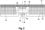
On a représenté sur la
Dans l'exemple de la
Ce logement 66 est formé par un décrochement 86 de la paroi 65 de la machine. Cette paroi 65 est dans l'exemple décrit une plaque arrière 87 de la machine électrique, à l'opposé par exemple du côté de la machine où se trouve la roue de compresseur. Cette plaque arrière 87 est par exemple réalisée en matériau, notamment plastique ou métallique.This
La carte électronique 62 comporte un orifice traversant 90 qui reçoit le capteur 61. Cet orifice 90 reçoit le décrochement 86 de la paroi. Une carte de contrôle 91 est posée sur la carte électronique 62. Cette carte de contrôle 91 porte le capteur 61, et cette carte de contrôle obture l'orifice 90 de la carte électronique.The
Claims (11)
- Electrical device (1), in particular for a motor vehicle, this electrical device including:- an electrical machine (7) including a rotary shaft (19),- a target (60) mounted on the rotary shaft,- a sensor (61) designed to interact with the target, in particular in order to deliver an item of information in relation to the angular position of the rotary shaft,- an electronic board (62; 91) bearing at least one data-processing unit (63), the sensor being mounted on this board and linked electrically to the processing unit,wherein the electrical machine includes a wall (65), in particular of a housing (8), which wall is provided with a through-aperture (66) to the right of which the target is positioned,
characterized in that the aperture receives a sealing element (70), in particular made of plastic, the sealing element being a part that is applied inside the aperture. - Electrical device according to the preceding claim, wherein the target (60) is a magnetic target, preferably designed to generate a magnetic field extending axially substantially along an axis of rotation of the shaft of the electrical machine, and the sensor is sensitive to this magnetic field.
- Electrical device according to either of the preceding claims, wherein the target is positioned at an end of the rotary shaft (19).
- Electrical device according to one of the preceding claims, wherein the target extends at least partly into the aperture (66).
- Electrical device according to one of the preceding claims, wherein the aperture opens out onto the electronic board (62).
- Electrical device according to one of the preceding claims, wherein the sensor (61) and the target (60) are respectively on either side of the wall (65).
- Electrical device according to one of the preceding claims, wherein the sensor is mounted on a face of the electronic board or of a control board, which face is oriented towards the aperture (66).
- Electrical device according to one of the preceding claims, wherein the electronic board includes an electrical connection (75) for electrically connecting the sensor and the processing unit, this connection extending into the thickness of the electronic board between the two faces of the board.
- Electrical device according to one of the preceding claims, wherein the electronic board extends substantially perpendicular to the axis of the shaft of the machine.
- Electrical device according to one of the preceding claims, forming an electrical charge air compressor for a motor vehicle.
- Electrical device according to the preceding claim, wherein the compressor includes a cooling channel (50) designed to cool at least one electronic assembly including the electronic board, this channel receiving a liquid coolant, for example water.
Applications Claiming Priority (1)
| Application Number | Priority Date | Filing Date | Title |
|---|---|---|---|
| FR1559682A FR3042328B1 (en) | 2015-10-12 | 2015-10-12 | ELECTRICAL EQUIPMENT, IN PARTICULAR FOR MOTOR VEHICLE |
Publications (2)
| Publication Number | Publication Date |
|---|---|
| EP3157142A1 EP3157142A1 (en) | 2017-04-19 |
| EP3157142B1 true EP3157142B1 (en) | 2019-08-28 |
Family
ID=55752338
Family Applications (1)
| Application Number | Title | Priority Date | Filing Date |
|---|---|---|---|
| EP16190727.4A Active EP3157142B1 (en) | 2015-10-12 | 2016-09-27 | Electrical system, in particular for a motor vehicle |
Country Status (2)
| Country | Link |
|---|---|
| EP (1) | EP3157142B1 (en) |
| FR (1) | FR3042328B1 (en) |
Families Citing this family (5)
| Publication number | Priority date | Publication date | Assignee | Title |
|---|---|---|---|---|
| JP6663467B2 (en) | 2017-11-22 | 2020-03-11 | 三菱重工業株式会社 | Centrifugal compressor and supercharger |
| DE112018008039T5 (en) * | 2018-10-26 | 2021-06-10 | Borgwarner Inc. | Rotary machine and method of using the same |
| FR3088501B1 (en) * | 2018-11-08 | 2021-10-22 | Valeo Equip Electr Moteur | DEVICE FOR DETECTION OF THE ANGULAR POSITION OF A ROTOR OF A ROTATING ELECTRIC MACHINE |
| CN110486290A (en) * | 2019-08-02 | 2019-11-22 | 中国航空工业集团公司金城南京机电液压工程研究中心 | A kind of canned motor pump |
| FR3123701B1 (en) * | 2021-06-08 | 2023-09-15 | Renault Sas | Gearbox with a waterproof magnetic sensor |
Citations (1)
| Publication number | Priority date | Publication date | Assignee | Title |
|---|---|---|---|---|
| US20120031215A1 (en) * | 2009-03-24 | 2012-02-09 | Magna Powertrain Ag & Co Kg | Transmission unit |
Family Cites Families (3)
| Publication number | Priority date | Publication date | Assignee | Title |
|---|---|---|---|---|
| DE102011089667A1 (en) * | 2011-12-22 | 2013-06-27 | Robert Bosch Gmbh | Electrical machine of boost recuperation system for motor car, has centering sleeve that is guided in area of bearing bore of bearing plates, and is firmly connected to base portion in radial direction |
| JP5777796B2 (en) * | 2012-11-22 | 2015-09-09 | 三菱重工業株式会社 | Supercharger with electric motor and engine device provided with supercharger with electric motor |
| JP5850263B2 (en) * | 2013-05-17 | 2016-02-03 | 株式会社デンソー | Drive device |
-
2015
- 2015-10-12 FR FR1559682A patent/FR3042328B1/en active Active
-
2016
- 2016-09-27 EP EP16190727.4A patent/EP3157142B1/en active Active
Patent Citations (1)
| Publication number | Priority date | Publication date | Assignee | Title |
|---|---|---|---|---|
| US20120031215A1 (en) * | 2009-03-24 | 2012-02-09 | Magna Powertrain Ag & Co Kg | Transmission unit |
Also Published As
| Publication number | Publication date |
|---|---|
| FR3042328A1 (en) | 2017-04-14 |
| EP3157142A1 (en) | 2017-04-19 |
| FR3042328B1 (en) | 2018-09-07 |
Similar Documents
| Publication | Publication Date | Title |
|---|---|---|
| EP3157142B1 (en) | Electrical system, in particular for a motor vehicle | |
| US6085527A (en) | Magnet assemblies for motor-assisted turbochargers | |
| WO2014209870A1 (en) | Supercharger for a combustion engine | |
| US9976561B2 (en) | Method for securing stator in high speed electric motors | |
| WO2017042235A1 (en) | Electric compressor | |
| FR3060896B1 (en) | ELECTRIC COMPRESSOR WITH COOLING CIRCUIT | |
| WO2017042236A1 (en) | Electric supercharging compressor | |
| FR2815671A1 (en) | Turbocompressor with electrical assistance, uses wheel of turbocompressor as induction motor rotor, with windings to create magnetic field on case of turbocompressor | |
| FR3044711B1 (en) | ELECTRIC COMPRESSOR WITH COOLING CIRCUIT | |
| WO2016207544A1 (en) | Bearing support | |
| WO2017055741A1 (en) | Electric compressor | |
| FR3043137B1 (en) | ELECTRIC COMPRESSOR WITH COOLING CIRCUIT | |
| FR3048033A1 (en) | ELECTRIC COMPRESSOR | |
| EP3707805A1 (en) | Axial-flux electromagnetic machine having a cooling circuit common to the machine and to its electronic control and power means | |
| FR3041699A1 (en) | ELECTRIC COMPRESSOR | |
| FR3055366B1 (en) | INTAKE AIR MANAGEMENT SYSTEM FOR A THERMAL MOTOR OF A MOTOR VEHICLE | |
| FR3062685A1 (en) | INTAKE AIR MANAGEMENT SYSTEM FOR A THERMAL MOTOR OF A MOTOR VEHICLE | |
| WO2017068293A1 (en) | Electric compressor | |
| EP3390835A1 (en) | Electric compressor | |
| WO2017046327A1 (en) | Electric compressor | |
| FR3048034A1 (en) | ELECTRIC COMPRESSOR | |
| FR3058487B1 (en) | CLUTCH COMPRISING A VENTILATED HOUSING | |
| FR3049994A1 (en) | ELECTRIC COMPRESSOR WITH COOLING CIRCUIT | |
| WO2018073496A1 (en) | Electric compressor with cooling circuit | |
| FR3051024A1 (en) | ELECTRIC COMPRESSOR WITH COOLING CIRCUIT |
Legal Events
| Date | Code | Title | Description |
|---|---|---|---|
| PUAI | Public reference made under article 153(3) epc to a published international application that has entered the european phase |
Free format text: ORIGINAL CODE: 0009012 |
|
| STAA | Information on the status of an ep patent application or granted ep patent |
Free format text: STATUS: REQUEST FOR EXAMINATION WAS MADE |
|
| 17P | Request for examination filed |
Effective date: 20160927 |
|
| AK | Designated contracting states |
Kind code of ref document: A1 Designated state(s): AL AT BE BG CH CY CZ DE DK EE ES FI FR GB GR HR HU IE IS IT LI LT LU LV MC MK MT NL NO PL PT RO RS SE SI SK SM TR |
|
| AX | Request for extension of the european patent |
Extension state: BA ME |
|
| STAA | Information on the status of an ep patent application or granted ep patent |
Free format text: STATUS: EXAMINATION IS IN PROGRESS |
|
| 17Q | First examination report despatched |
Effective date: 20170613 |
|
| GRAP | Despatch of communication of intention to grant a patent |
Free format text: ORIGINAL CODE: EPIDOSNIGR1 |
|
| STAA | Information on the status of an ep patent application or granted ep patent |
Free format text: STATUS: GRANT OF PATENT IS INTENDED |
|
| INTG | Intention to grant announced |
Effective date: 20190327 |
|
| GRAS | Grant fee paid |
Free format text: ORIGINAL CODE: EPIDOSNIGR3 |
|
| GRAA | (expected) grant |
Free format text: ORIGINAL CODE: 0009210 |
|
| STAA | Information on the status of an ep patent application or granted ep patent |
Free format text: STATUS: THE PATENT HAS BEEN GRANTED |
|
| AK | Designated contracting states |
Kind code of ref document: B1 Designated state(s): AL AT BE BG CH CY CZ DE DK EE ES FI FR GB GR HR HU IE IS IT LI LT LU LV MC MK MT NL NO PL PT RO RS SE SI SK SM TR |
|
| REG | Reference to a national code |
Ref country code: GB Ref legal event code: FG4D Free format text: NOT ENGLISH |
|
| REG | Reference to a national code |
Ref country code: CH Ref legal event code: EP |
|
| REG | Reference to a national code |
Ref country code: AT Ref legal event code: REF Ref document number: 1173616 Country of ref document: AT Kind code of ref document: T Effective date: 20190915 |
|
| REG | Reference to a national code |
Ref country code: IE Ref legal event code: FG4D Free format text: LANGUAGE OF EP DOCUMENT: FRENCH |
|
| REG | Reference to a national code |
Ref country code: DE Ref legal event code: R096 Ref document number: 602016019299 Country of ref document: DE |
|
| REG | Reference to a national code |
Ref country code: NL Ref legal event code: MP Effective date: 20190828 |
|
| REG | Reference to a national code |
Ref country code: LT Ref legal event code: MG4D |
|
| PG25 | Lapsed in a contracting state [announced via postgrant information from national office to epo] |
Ref country code: PT Free format text: LAPSE BECAUSE OF FAILURE TO SUBMIT A TRANSLATION OF THE DESCRIPTION OR TO PAY THE FEE WITHIN THE PRESCRIBED TIME-LIMIT Effective date: 20191230 Ref country code: FI Free format text: LAPSE BECAUSE OF FAILURE TO SUBMIT A TRANSLATION OF THE DESCRIPTION OR TO PAY THE FEE WITHIN THE PRESCRIBED TIME-LIMIT Effective date: 20190828 Ref country code: SE Free format text: LAPSE BECAUSE OF FAILURE TO SUBMIT A TRANSLATION OF THE DESCRIPTION OR TO PAY THE FEE WITHIN THE PRESCRIBED TIME-LIMIT Effective date: 20190828 Ref country code: NO Free format text: LAPSE BECAUSE OF FAILURE TO SUBMIT A TRANSLATION OF THE DESCRIPTION OR TO PAY THE FEE WITHIN THE PRESCRIBED TIME-LIMIT Effective date: 20191128 Ref country code: NL Free format text: LAPSE BECAUSE OF FAILURE TO SUBMIT A TRANSLATION OF THE DESCRIPTION OR TO PAY THE FEE WITHIN THE PRESCRIBED TIME-LIMIT Effective date: 20190828 Ref country code: BG Free format text: LAPSE BECAUSE OF FAILURE TO SUBMIT A TRANSLATION OF THE DESCRIPTION OR TO PAY THE FEE WITHIN THE PRESCRIBED TIME-LIMIT Effective date: 20191128 Ref country code: HR Free format text: LAPSE BECAUSE OF FAILURE TO SUBMIT A TRANSLATION OF THE DESCRIPTION OR TO PAY THE FEE WITHIN THE PRESCRIBED TIME-LIMIT Effective date: 20190828 Ref country code: LT Free format text: LAPSE BECAUSE OF FAILURE TO SUBMIT A TRANSLATION OF THE DESCRIPTION OR TO PAY THE FEE WITHIN THE PRESCRIBED TIME-LIMIT Effective date: 20190828 |
|
| PG25 | Lapsed in a contracting state [announced via postgrant information from national office to epo] |
Ref country code: AL Free format text: LAPSE BECAUSE OF FAILURE TO SUBMIT A TRANSLATION OF THE DESCRIPTION OR TO PAY THE FEE WITHIN THE PRESCRIBED TIME-LIMIT Effective date: 20190828 Ref country code: LV Free format text: LAPSE BECAUSE OF FAILURE TO SUBMIT A TRANSLATION OF THE DESCRIPTION OR TO PAY THE FEE WITHIN THE PRESCRIBED TIME-LIMIT Effective date: 20190828 Ref country code: GR Free format text: LAPSE BECAUSE OF FAILURE TO SUBMIT A TRANSLATION OF THE DESCRIPTION OR TO PAY THE FEE WITHIN THE PRESCRIBED TIME-LIMIT Effective date: 20191129 Ref country code: ES Free format text: LAPSE BECAUSE OF FAILURE TO SUBMIT A TRANSLATION OF THE DESCRIPTION OR TO PAY THE FEE WITHIN THE PRESCRIBED TIME-LIMIT Effective date: 20190828 Ref country code: RS Free format text: LAPSE BECAUSE OF FAILURE TO SUBMIT A TRANSLATION OF THE DESCRIPTION OR TO PAY THE FEE WITHIN THE PRESCRIBED TIME-LIMIT Effective date: 20190828 Ref country code: IS Free format text: LAPSE BECAUSE OF FAILURE TO SUBMIT A TRANSLATION OF THE DESCRIPTION OR TO PAY THE FEE WITHIN THE PRESCRIBED TIME-LIMIT Effective date: 20191228 |
|
| REG | Reference to a national code |
Ref country code: AT Ref legal event code: MK05 Ref document number: 1173616 Country of ref document: AT Kind code of ref document: T Effective date: 20190828 |
|
| PG25 | Lapsed in a contracting state [announced via postgrant information from national office to epo] |
Ref country code: TR Free format text: LAPSE BECAUSE OF FAILURE TO SUBMIT A TRANSLATION OF THE DESCRIPTION OR TO PAY THE FEE WITHIN THE PRESCRIBED TIME-LIMIT Effective date: 20190828 |
|
| PG25 | Lapsed in a contracting state [announced via postgrant information from national office to epo] |
Ref country code: RO Free format text: LAPSE BECAUSE OF FAILURE TO SUBMIT A TRANSLATION OF THE DESCRIPTION OR TO PAY THE FEE WITHIN THE PRESCRIBED TIME-LIMIT Effective date: 20190828 Ref country code: PL Free format text: LAPSE BECAUSE OF FAILURE TO SUBMIT A TRANSLATION OF THE DESCRIPTION OR TO PAY THE FEE WITHIN THE PRESCRIBED TIME-LIMIT Effective date: 20190828 Ref country code: DK Free format text: LAPSE BECAUSE OF FAILURE TO SUBMIT A TRANSLATION OF THE DESCRIPTION OR TO PAY THE FEE WITHIN THE PRESCRIBED TIME-LIMIT Effective date: 20190828 Ref country code: EE Free format text: LAPSE BECAUSE OF FAILURE TO SUBMIT A TRANSLATION OF THE DESCRIPTION OR TO PAY THE FEE WITHIN THE PRESCRIBED TIME-LIMIT Effective date: 20190828 Ref country code: IT Free format text: LAPSE BECAUSE OF FAILURE TO SUBMIT A TRANSLATION OF THE DESCRIPTION OR TO PAY THE FEE WITHIN THE PRESCRIBED TIME-LIMIT Effective date: 20190828 Ref country code: AT Free format text: LAPSE BECAUSE OF FAILURE TO SUBMIT A TRANSLATION OF THE DESCRIPTION OR TO PAY THE FEE WITHIN THE PRESCRIBED TIME-LIMIT Effective date: 20190828 |
|
| PG25 | Lapsed in a contracting state [announced via postgrant information from national office to epo] |
Ref country code: SM Free format text: LAPSE BECAUSE OF FAILURE TO SUBMIT A TRANSLATION OF THE DESCRIPTION OR TO PAY THE FEE WITHIN THE PRESCRIBED TIME-LIMIT Effective date: 20190828 Ref country code: CZ Free format text: LAPSE BECAUSE OF FAILURE TO SUBMIT A TRANSLATION OF THE DESCRIPTION OR TO PAY THE FEE WITHIN THE PRESCRIBED TIME-LIMIT Effective date: 20190828 Ref country code: IS Free format text: LAPSE BECAUSE OF FAILURE TO SUBMIT A TRANSLATION OF THE DESCRIPTION OR TO PAY THE FEE WITHIN THE PRESCRIBED TIME-LIMIT Effective date: 20200224 Ref country code: MC Free format text: LAPSE BECAUSE OF FAILURE TO SUBMIT A TRANSLATION OF THE DESCRIPTION OR TO PAY THE FEE WITHIN THE PRESCRIBED TIME-LIMIT Effective date: 20190828 Ref country code: SK Free format text: LAPSE BECAUSE OF FAILURE TO SUBMIT A TRANSLATION OF THE DESCRIPTION OR TO PAY THE FEE WITHIN THE PRESCRIBED TIME-LIMIT Effective date: 20190828 |
|
| REG | Reference to a national code |
Ref country code: CH Ref legal event code: PL |
|
| REG | Reference to a national code |
Ref country code: DE Ref legal event code: R097 Ref document number: 602016019299 Country of ref document: DE |
|
| PLBE | No opposition filed within time limit |
Free format text: ORIGINAL CODE: 0009261 |
|
| STAA | Information on the status of an ep patent application or granted ep patent |
Free format text: STATUS: NO OPPOSITION FILED WITHIN TIME LIMIT |
|
| PG2D | Information on lapse in contracting state deleted |
Ref country code: IS |
|
| PG25 | Lapsed in a contracting state [announced via postgrant information from national office to epo] |
Ref country code: IE Free format text: LAPSE BECAUSE OF NON-PAYMENT OF DUE FEES Effective date: 20190927 Ref country code: LU Free format text: LAPSE BECAUSE OF NON-PAYMENT OF DUE FEES Effective date: 20190927 Ref country code: LI Free format text: LAPSE BECAUSE OF NON-PAYMENT OF DUE FEES Effective date: 20190930 Ref country code: CH Free format text: LAPSE BECAUSE OF NON-PAYMENT OF DUE FEES Effective date: 20190930 |
|
| REG | Reference to a national code |
Ref country code: BE Ref legal event code: MM Effective date: 20190930 |
|
| 26N | No opposition filed |
Effective date: 20200603 |
|
| PG25 | Lapsed in a contracting state [announced via postgrant information from national office to epo] |
Ref country code: BE Free format text: LAPSE BECAUSE OF NON-PAYMENT OF DUE FEES Effective date: 20190930 Ref country code: SI Free format text: LAPSE BECAUSE OF FAILURE TO SUBMIT A TRANSLATION OF THE DESCRIPTION OR TO PAY THE FEE WITHIN THE PRESCRIBED TIME-LIMIT Effective date: 20190828 |
|
| GBPC | Gb: european patent ceased through non-payment of renewal fee |
Effective date: 20200927 |
|
| PG25 | Lapsed in a contracting state [announced via postgrant information from national office to epo] |
Ref country code: CY Free format text: LAPSE BECAUSE OF FAILURE TO SUBMIT A TRANSLATION OF THE DESCRIPTION OR TO PAY THE FEE WITHIN THE PRESCRIBED TIME-LIMIT Effective date: 20190828 |
|
| PG25 | Lapsed in a contracting state [announced via postgrant information from national office to epo] |
Ref country code: HU Free format text: LAPSE BECAUSE OF FAILURE TO SUBMIT A TRANSLATION OF THE DESCRIPTION OR TO PAY THE FEE WITHIN THE PRESCRIBED TIME-LIMIT; INVALID AB INITIO Effective date: 20160927 Ref country code: MT Free format text: LAPSE BECAUSE OF FAILURE TO SUBMIT A TRANSLATION OF THE DESCRIPTION OR TO PAY THE FEE WITHIN THE PRESCRIBED TIME-LIMIT Effective date: 20190828 |
|
| PG25 | Lapsed in a contracting state [announced via postgrant information from national office to epo] |
Ref country code: GB Free format text: LAPSE BECAUSE OF NON-PAYMENT OF DUE FEES Effective date: 20200927 |
|
| PG25 | Lapsed in a contracting state [announced via postgrant information from national office to epo] |
Ref country code: MK Free format text: LAPSE BECAUSE OF FAILURE TO SUBMIT A TRANSLATION OF THE DESCRIPTION OR TO PAY THE FEE WITHIN THE PRESCRIBED TIME-LIMIT Effective date: 20190828 |
|
| P01 | Opt-out of the competence of the unified patent court (upc) registered |
Effective date: 20230528 |
|
| PGFP | Annual fee paid to national office [announced via postgrant information from national office to epo] |
Ref country code: FR Payment date: 20230927 Year of fee payment: 8 Ref country code: DE Payment date: 20230911 Year of fee payment: 8 |