EP3156680A2 - Kupplung mit abstimmelement zur beeinflussung des akustischen verhaltens der kupplung - Google Patents
Kupplung mit abstimmelement zur beeinflussung des akustischen verhaltens der kupplung Download PDFInfo
- Publication number
- EP3156680A2 EP3156680A2 EP16001881.8A EP16001881A EP3156680A2 EP 3156680 A2 EP3156680 A2 EP 3156680A2 EP 16001881 A EP16001881 A EP 16001881A EP 3156680 A2 EP3156680 A2 EP 3156680A2
- Authority
- EP
- European Patent Office
- Prior art keywords
- tuning element
- coupling part
- coupling
- clutch
- outer coupling
- Prior art date
- Legal status (The legal status is an assumption and is not a legal conclusion. Google has not performed a legal analysis and makes no representation as to the accuracy of the status listed.)
- Granted
Links
Images

Classifications
-
- F—MECHANICAL ENGINEERING; LIGHTING; HEATING; WEAPONS; BLASTING
- F16—ENGINEERING ELEMENTS AND UNITS; GENERAL MEASURES FOR PRODUCING AND MAINTAINING EFFECTIVE FUNCTIONING OF MACHINES OR INSTALLATIONS; THERMAL INSULATION IN GENERAL
- F16D—COUPLINGS FOR TRANSMITTING ROTATION; CLUTCHES; BRAKES
- F16D13/00—Friction clutches
- F16D13/22—Friction clutches with axially-movable clutching members
- F16D13/38—Friction clutches with axially-movable clutching members with flat clutching surfaces, e.g. discs
- F16D13/52—Clutches with multiple lamellae ; Clutches in which three or more axially moveable members are fixed alternately to the shafts to be coupled and are pressed from one side towards an axially-located member
-
- F—MECHANICAL ENGINEERING; LIGHTING; HEATING; WEAPONS; BLASTING
- F16—ENGINEERING ELEMENTS AND UNITS; GENERAL MEASURES FOR PRODUCING AND MAINTAINING EFFECTIVE FUNCTIONING OF MACHINES OR INSTALLATIONS; THERMAL INSULATION IN GENERAL
- F16D—COUPLINGS FOR TRANSMITTING ROTATION; CLUTCHES; BRAKES
- F16D13/00—Friction clutches
- F16D13/58—Details
-
- F—MECHANICAL ENGINEERING; LIGHTING; HEATING; WEAPONS; BLASTING
- F16—ENGINEERING ELEMENTS AND UNITS; GENERAL MEASURES FOR PRODUCING AND MAINTAINING EFFECTIVE FUNCTIONING OF MACHINES OR INSTALLATIONS; THERMAL INSULATION IN GENERAL
- F16D—COUPLINGS FOR TRANSMITTING ROTATION; CLUTCHES; BRAKES
- F16D13/00—Friction clutches
- F16D13/58—Details
- F16D13/60—Clutching elements
- F16D13/62—Clutch-bands; Clutch shoes; Clutch-drums
-
- F—MECHANICAL ENGINEERING; LIGHTING; HEATING; WEAPONS; BLASTING
- F16—ENGINEERING ELEMENTS AND UNITS; GENERAL MEASURES FOR PRODUCING AND MAINTAINING EFFECTIVE FUNCTIONING OF MACHINES OR INSTALLATIONS; THERMAL INSULATION IN GENERAL
- F16D—COUPLINGS FOR TRANSMITTING ROTATION; CLUTCHES; BRAKES
- F16D13/00—Friction clutches
- F16D13/58—Details
- F16D13/60—Clutching elements
- F16D13/64—Clutch-plates; Clutch-lamellae
- F16D13/648—Clutch-plates; Clutch-lamellae for clutches with multiple lamellae
-
- F—MECHANICAL ENGINEERING; LIGHTING; HEATING; WEAPONS; BLASTING
- F16—ENGINEERING ELEMENTS AND UNITS; GENERAL MEASURES FOR PRODUCING AND MAINTAINING EFFECTIVE FUNCTIONING OF MACHINES OR INSTALLATIONS; THERMAL INSULATION IN GENERAL
- F16D—COUPLINGS FOR TRANSMITTING ROTATION; CLUTCHES; BRAKES
- F16D3/00—Yielding couplings, i.e. with means permitting movement between the connected parts during the drive
- F16D3/50—Yielding couplings, i.e. with means permitting movement between the connected parts during the drive with the coupling parts connected by one or more intermediate members
- F16D3/56—Yielding couplings, i.e. with means permitting movement between the connected parts during the drive with the coupling parts connected by one or more intermediate members comprising elastic metal lamellae, elastic rods, or the like, e.g. arranged radially or parallel to the axis, the members being shear-loaded collectively by the total load
- F16D3/58—Yielding couplings, i.e. with means permitting movement between the connected parts during the drive with the coupling parts connected by one or more intermediate members comprising elastic metal lamellae, elastic rods, or the like, e.g. arranged radially or parallel to the axis, the members being shear-loaded collectively by the total load the intermediate members being made of rubber or like material
-
- F—MECHANICAL ENGINEERING; LIGHTING; HEATING; WEAPONS; BLASTING
- F16—ENGINEERING ELEMENTS AND UNITS; GENERAL MEASURES FOR PRODUCING AND MAINTAINING EFFECTIVE FUNCTIONING OF MACHINES OR INSTALLATIONS; THERMAL INSULATION IN GENERAL
- F16D—COUPLINGS FOR TRANSMITTING ROTATION; CLUTCHES; BRAKES
- F16D7/00—Slip couplings, e.g. slipping on overload, for absorbing shock
- F16D7/02—Slip couplings, e.g. slipping on overload, for absorbing shock of the friction type
-
- F—MECHANICAL ENGINEERING; LIGHTING; HEATING; WEAPONS; BLASTING
- F16—ENGINEERING ELEMENTS AND UNITS; GENERAL MEASURES FOR PRODUCING AND MAINTAINING EFFECTIVE FUNCTIONING OF MACHINES OR INSTALLATIONS; THERMAL INSULATION IN GENERAL
- F16F—SPRINGS; SHOCK-ABSORBERS; MEANS FOR DAMPING VIBRATION
- F16F15/00—Suppression of vibrations in systems; Means or arrangements for avoiding or reducing out-of-balance forces, e.g. due to motion
- F16F15/10—Suppression of vibrations in rotating systems by making use of members moving with the system
-
- F—MECHANICAL ENGINEERING; LIGHTING; HEATING; WEAPONS; BLASTING
- F16—ENGINEERING ELEMENTS AND UNITS; GENERAL MEASURES FOR PRODUCING AND MAINTAINING EFFECTIVE FUNCTIONING OF MACHINES OR INSTALLATIONS; THERMAL INSULATION IN GENERAL
- F16D—COUPLINGS FOR TRANSMITTING ROTATION; CLUTCHES; BRAKES
- F16D2300/00—Special features for couplings or clutches
- F16D2300/22—Vibration damping
-
- F—MECHANICAL ENGINEERING; LIGHTING; HEATING; WEAPONS; BLASTING
- F16—ENGINEERING ELEMENTS AND UNITS; GENERAL MEASURES FOR PRODUCING AND MAINTAINING EFFECTIVE FUNCTIONING OF MACHINES OR INSTALLATIONS; THERMAL INSULATION IN GENERAL
- F16D—COUPLINGS FOR TRANSMITTING ROTATION; CLUTCHES; BRAKES
- F16D25/00—Fluid-actuated clutches
- F16D25/06—Fluid-actuated clutches in which the fluid actuates a piston incorporated in, i.e. rotating with the clutch
- F16D25/062—Fluid-actuated clutches in which the fluid actuates a piston incorporated in, i.e. rotating with the clutch the clutch having friction surfaces
- F16D25/063—Fluid-actuated clutches in which the fluid actuates a piston incorporated in, i.e. rotating with the clutch the clutch having friction surfaces with clutch members exclusively moving axially
- F16D25/0635—Fluid-actuated clutches in which the fluid actuates a piston incorporated in, i.e. rotating with the clutch the clutch having friction surfaces with clutch members exclusively moving axially with flat friction surfaces, e.g. discs
- F16D25/0638—Fluid-actuated clutches in which the fluid actuates a piston incorporated in, i.e. rotating with the clutch the clutch having friction surfaces with clutch members exclusively moving axially with flat friction surfaces, e.g. discs with more than two discs, e.g. multiple lamellae
Definitions
- the invention relates to a clutch, in particular a multi-plate clutch, preferably for a transmission of torques, suitable alternating torques, in particular pronounced rotational irregularity between a power and a prime mover.
- Multi-disc clutches generally consist of a clutch pot, a clutch hub and disc packs, wherein in each case a disc pack with the clutch hub and a disc pack is positively connected to the clutch pot.
- a power transmission takes place from the clutch pot via the disk packs to the clutch hub.
- a radial play must be present in the form-fitting connections of the disk sets with their connected components (clutch pot with a disk set and clutch hub with the other disk set).
- This game generates a change of investment of positively connected components, which can lead to particular beating noise between the edges of the positive connections.
- the coupling pot emits frequency components due to this transient excitation, which directly depend on the eigenmodes, natural frequencies and the modal damping of these eigenmodes and correlate with the resulting structure-borne sound components.
- An object of the invention is to avoid or reduce undesirable clutch noises, preferably to modify or detune them into preferred and / or specific functional / operating noises.
- the invention relates to a coupling, in particular a multi-plate clutch, with an outer coupling part and an inner coupling part.
- the outer coupling part is preferably a clutch pot, in particular an outer disk carrier.
- the inner coupling part is preferably a clutch hub, in particular an inner plate carrier.
- the outer coupling part and the inner coupling part are preferably arranged substantially coaxially with each other.
- the coupling is characterized in particular in that a preferably substantially annular tuning element expediently surrounds the outer coupling part at least in sections.
- the tuning element is preferably used to influence the acoustic behavior of the coupling, in particular the acoustic behavior of the outer coupling part.
- the tuning element serves in particular for influencing the psychoacoustic behavior and / or for expediently outside sheathing of the outer coupling part.
- tuning element By the tuning element, it is expediently possible that unwanted noise of the clutch is reduced and / or detuned into preferred functional and / or operating noise.
- the coupling can be tuned by means of the Abstimmelements in particular by a mass and / or stiffness assignment of the outer coupling part so that natural vibration modes and / or natural frequencies of the outer coupling part are adjustable so that an airborne sound radiation is minimized and / or displaceable in a frequency range, the is not perceived as disturbing.
- the material and / or the geometry of the tuning element affect its mechanical partial mass, stiffness and / or joint damping properties.
- the tuning element may suitably detune or modify eigenmodes and / or natural frequencies of the clutch noises, in particular of the outer clutch part, in such a way that a preferred functional and / or operating noise is achieved, eg. B. in that by damping the eigenmodes and / or natural frequencies, the acoustic behavior of the coupling, in particular the outer coupling part, can be designed.
- Vibratory systems may conveniently be described modulatively discretely by a matrix of n * m coupled spring-mass systems.
- the design of the acoustic behavior can be carried out, in particular, essentially by deliberately influencing the pulse strength and / or the modulation of individual coupling noise frequency groups.
- emphasis may be placed on and / or suppression of defined, application-related, clutch noise frequency groups be targeted that thereby the fluctuation strength and / or the roughness of the emitted coupling noise can be adjusted by influencing the modal parameters by material and / or joint damping (Fügestellendämpfung) and alternatively or additionally elasticity and / or shear modulus of the tuning.
- the tuning element makes it possible, in particular, for the mass, stiffness and / or damping matrices of the coupling, in particular of the outer coupling part, to be independent of the material properties thereof, as a result of the material and / or joint damping and, alternatively or additionally, the elasticity and / or shear modulus are modifiable such that the modal parameters change due to the differences in the material and / or joint damping as well as alternatively or additionally the elasticity and / or shear modulus in the tuning element and outer coupling part to the effect that the psychoacoustic parameters in sum to a preferred coupling -Functional or operating noise, so that z. B. unwanted clutch noise can be reduced or avoided.
- the tuning element may be applied to the outer coupling part such that the joint damping between the outer coupling part and tuning element is influenced by the coefficient of friction therebetween and / or by tangential tension in the outer coupling part and tuning element (for example, is set).
- this damping can be selected by selecting the material (in particular material) of the tuning element and its specific material damping preferred.
- the joint damping in the friction gap between the outer coupling part and the tuning element is caused in particular by micro-movements.
- the tuning element may preferably be applied to the outer coupling part with friction, for. B. abut friction on the outer coupling part, z. B. in the circumferential direction of the outer coupling part.
- the tuning element is formed of at least two different materials, for. B. different in terms of mass, stiffness and / or noise damping.
- the tangential preload and elastic characteristics (for example the modulus of elasticity) of the tuning element can advantageously influence the stiffness matrix of the outer coupling part with the tuning element applied.
- the tuning element may comprise, for example, an elastomer, different elastomers, a duroplastic, different duroplastic materials, a thermoplastic material and / or different thermoplastic materials.
- the material can additionally z. B. at least one additional material, a strength-increasing additive and / or fibers be incorporated.
- the tuning element may suitably have different layer thicknesses.
- the tuning element may have a suitably different partial mass distribution. It can thus comprise at least two sections a different layer thickness and / or partial mass distribution.
- the mass matrix of the combination of outer coupling part and tuning element can be influenced.
- the tuning element may be applied to the outer coupling part substantially without bias, so that the bias voltage may be substantially zero.
- the tuning element can be applied with bias to the outer coupling part, in particular to be clamped.
- the tuning element is shrunk thermally and / or chemically to the outer coupling part.
- the tuning element may be mechanically biased to the outer coupling part.
- the tuning element is preferably a substantially annular tuning ring.
- the outer coupling part is preferably substantially annular.
- the inner coupling part is preferably substantially annular.
- the clutch is preferably a multi-plate clutch, so that disk packs between the outer coupling part and the inner coupling part can be arranged, preferably in each case a disk set with the outer coupling part and a disk set with the inner coupling part are positively connected. It is possible that a power transmission from the outer coupling part via the disk packs takes place on the inner coupling part when the disk packs are pressed against each other. It is possible that the outer coupling part serves as a coupling output and the inner coupling part as a coupling drive or vice versa.
- the tuning element in particular material and / or geometry-related, expediently influences the acoustic behavior of the coupling, preferably by influencing the joint damping between the tuning element and the outer coupling part, the rigidity and / or the mass of the outer coupling part and the tuning element comprehensive arrangement.
- the coupling is used in particular for the transmission of torques, z. B. alternating torques, in particular pronounced rotational irregularity between a power and a working machine.
- FIG. 1 shows a perspective view of a coupling K according to an embodiment of the invention.
- the clutch K will be described below with reference to the common FIGS. 1 to 3 described.
- the clutch K is designed as a multi-plate clutch (either dry or in an oil bath) with a suitably annular clutch pot 1 (outer clutch part) and a suitably annular clutch hub 2 (inner clutch part).
- Disk packs 3 and 4 which are also suitably annular, are interposed between the clutch pot 1 and the clutch hub 2.
- the disk set 4 is positively connected to the clutch pot 1 and the disk set 3 is positively connected to the clutch hub 2. If the disk sets 3 and 4 are pressed against each other, a power transmission takes place from the coupling pot 1 via the disk sets 3 and 4 to the clutch hub 2.
- a radial clearance in the positive connections available In order to enable a shift of the clutch K for the preparation or for the separation of the frictional connection, in the form-locking connections of the disk sets 3 and 4 with the clutch pot 1 and the clutch hub 2, a radial clearance in the positive connections available.
- the radial play can produce a change in the system of the positively connected components, which leads to undesirable, for example, beating noises between the flanks of the positive connections.
- the coupling pot 1 emits transient excitation frequency components, which depend directly on the eigen modes, natural frequencies and the modal attenuation of these eigenmodes and correlate with the resulting structure-borne sound components.
- the coupling K is therefore provided with a tuning ring 5 (tuning element) for influencing the acoustic behavior of the coupling K, in particular of the coupling pot 1.
- the tuning ring 5 encases the clutch pot 1 and, suitably directly and with friction, applied to the clutch pot 1, z. B. with bias or substantially free of bias.
- Vibratory systems such as coupling K, can be described modally by a matrix of n * m coupled spring-mass systems.
- eigenmodes can be detuned in such a way that a preferred functional or operating noise is achieved by the acoustic behavior of the coupling plug due to the damping of the eigenmodes and frequencies 1 is specially designed.
- this design is done by selectively influencing the pulse strength and the modulation of individual frequency groups.
- emphasis is placed on the emphasis and suppression of defined, application-related frequency groups by the fact that the fluctuation strength and the roughness of the emitted overall noise can be adjusted by influencing the modal parameters by material and joint damping (joint cushioning) as well as elasticity and shear modulus of the tuning element 5.
- the tuning ring 5 is applied to the clutch pot 1, that the joint damping between the tuning ring 5 and the clutch pot 1 by the coefficient of friction between and by Tangentialschreib in the clutch pot 1 and 5 in the tuning ring is adjustable. This leads to a direct influence on the attenuation matrix of the overall arrangement.
- the damping matrix of the arrangement of outer coupling part 1 and tuning ring 5 by selecting the material (in particular material) of the tuning ring 5 and its specific material damping is preferably selected.
- the tangential preload of the tuning ring 5 and elastic characteristics (eg modulus of elasticity) of the material (in particular material) of the tuning ring 5 can influence the rigidity matrix of the arrangement outer coupling part 1 / tuning ring 5.
- a different partial mass distribution and layer thickness of the tuning ring 5 can lead to influencing the mass matrix.
- the tuning ring 5 is preferably made of an elastomer or a thermosetting or thermoplastic material or both.
- the addition of fillers and / or strength-increasing additives and / or fibers can also bring about desired, preferably psychoacoustic properties.
- the bias of the tuning ring 5 may also assume the value of substantially 0, so that only the material damping and / or the partial mass distribution of the tuning ring 5 comes into play.
- a speed adaptive adaptation of the psychoacoustic design of the functional and operating noises can be achieved by counteracting centrifugal forces of the tangential stress directly and / or indirectly.
- a temperature-dependent adaptation of the noise emission can be achieved by adapting the thermodynamic properties of the tuning ring 5.
Landscapes
- Engineering & Computer Science (AREA)
- General Engineering & Computer Science (AREA)
- Mechanical Engineering (AREA)
- Physics & Mathematics (AREA)
- Acoustics & Sound (AREA)
- Aviation & Aerospace Engineering (AREA)
- Mechanical Operated Clutches (AREA)
- Hydraulic Clutches, Magnetic Clutches, Fluid Clutches, And Fluid Joints (AREA)
- Braking Arrangements (AREA)
Abstract
Description
- Die Erfindung betrifft eine Kupplung, insbesondere eine Lamellenkupplung, vorzugsweise für eine Übertragung von Drehmomenten, zweckmäßig Wechseldrehmomenten, mit insbesondere ausgeprägter Drehungleichförmigkeit zwischen einer Kraft- und einer Antriebsmaschine.
- Lamellenkupplungen bestehen im Allgemeinen aus einem Kupplungstopf, einer Kupplungsnabe und Lamellenpaketen, wobei jeweils ein Lamellenpaket mit der Kupplungsnabe und ein Lamellenpaket mit dem Kupplungstopf formschlüssig verbunden ist. Wenn die Lamellenpakete gegeneinander gepresst werden, findet eine Kraftübertragung vom Kupplungstopf über die Lamellenpakete auf die Kupplungsnabe statt. Um ein Schalten der Lamellenkupplung zur Herstellung beziehungsweise zum Trennen des Kraftschlusses zu ermöglichen, muss in den formschlüssigen Verbindungen der Lamellenpakete mit ihren angeschlossenen Bauteilen (Kupplungstopf mit dem einen Lamellenpaket sowie Kupplungsnabe mit dem anderen Lamellenpaket) ein radiales Spiel im Formschluss vorhanden sein. Dieses Spiel erzeugt einen Anlagewechsel der formschlüssig verbundenen Bauteile, was zu insbesondere schlagenden Geräuschen zwischen den Flanken der formschlüssigen Verbindungen führen kann. Vor allem der Kupplungstopf strahlt durch diese transiente Anregung Frequenzanteile ab, die von den Eigenformen, Eigenfrequenzen und den modalen Dämpfungen dieser Eigenformen direkt abhängen und mit den entstehenden Körperschallanteilen korrelieren.
- Eine Aufgabe der Erfindung ist es, unerwünschte Kupplungsgeräusche zu vermeiden oder zu reduzieren, vorzugsweise in bevorzugte und/oder bestimmte Funktions-/Betriebsgeräusche zu modifizieren bzw. zu verstimmen.
- Diese Aufgabe kann mit den Merkmalen des Hauptanspruchs gelöst werden. Vorteilhafte Weiterbildungen der Erfindung können den Unteransprüchen und der folgenden Beschreibung bevorzugter Ausführungsformen der Erfindung entnommen werden.
- Die Erfindung betrifft eine Kupplung, insbesondere eine Lamellenkupplung, mit einem äußeren Kupplungsteil und einem inneren Kupplungsteil. Das äußere Kupplungsteil ist vorzugsweise ein Kupplungstopf, insbesondere ein äußerer Lamellenträger. Das innere Kupplungsteil ist vorzugsweise eine Kupplungsnabe, insbesondere ein innerer Lamellenträger.
- Das äußere Kupplungsteil und das innere Kupplungsteil sind vorzugsweise im Wesentlichen koaxial zueinander angeordnet.
- Die Kupplung zeichnet sich insbesondere dadurch aus, dass ein vorzugsweise im Wesentlichen ringförmiges Abstimmelement das äußere Kupplungsteil zweckmäßig zumindest abschnittsweise ummantelt. Das Abstimmelement dient vorzugsweise zur Beeinflussung des akustischen Verhaltens der Kupplung, insbesondere des akustischen Verhaltens des äußeren Kupplungsteils. Das Abstimmelement dient dabei insbesondere zur Beeinflussung des psychoakustischen Verhaltens und/oder zur zweckmäßig außenseitigen Ummantelung des äußeren Kupplungsteils.
- Durch das Abstimmelement ist es zweckmäßig möglich, dass unerwünschte Geräusche der Kupplung reduziert und/oder in bevorzugte Funktion- und/oder Betriebsgeräusche verstimmt werden.
- Die Kupplung kann mittels des Abstimmelements insbesondere durch eine Masse- und/oder Steifigkeitsbelegung des äußeren Kupplungsteils so abgestimmt werden, dass Eigenschwingformen und/oder Eigenfrequenzen des äußeren Kupplungsteils so einstellbar sind, dass eine Luftschallabstrahlung minimierbar ist und/oder in einen Frequenzbereich verschiebbar ist, der als nicht störend wahrgenommen wird.
- Das Material und/oder die Geometrie des Abstimmelements beeinflussen seine mechanischen partiellen Masse-, Steifigkeits- und/oder Fügestellungsdämpfungs-Eigenschaften.
- Das Abstimmelement kann zweckmäßig Eigenformen und/oder Eigenfrequenzen der Kupplungsgeräusche, insbesondere des äußeren Kupplungsteils, so verstimmen bzw. modifizieren, dass ein bevorzugtes Funktions- und/oder Betriebsgeräusch erreicht wird, z. B. dadurch, dass durch Bedämpfung der Eigenformen und/oder Eigenfrequenzen das akustische Verhalten der Kupplung, insbesondere des äußeren Kupplungsteils, gestaltet werden kann.
- Schwingfähige Systeme können zweckmäßig diskret durch eine Matrix von n*m gekoppelten Feder-Masse-Systemen modal beschrieben werden.
- Die Gestaltung des akustischen Verhaltens kann insbesondere im Wesentlichen durch gezielte Beeinflussung der Impulshaftigkeit und/oder der Modulation einzelner Kupplungsgeräusch-Frequenzgruppen erfolgen. Alternativ oder ergänzend kann auf eine Betonung und/oder Unterdrückung definierter, anwendungsbezogener Kupplungsgeräusch-Frequenzgruppen dadurch abgezielt werden, dass hierdurch die Schwankungsstärke und/oder die Rauigkeit des emittierten Kupplungs-Gesamtgeräusches durch die Beeinflussung der Modalparameter durch Material- und/oder Fügestellungdämpfung (Fügestellendämpfung) und alternativ oder ergänzend Elastizitäts-und/oder Schubmodul des Abstimmelementes eingestellt werden kann.
- Das Abstimmelement ermöglicht insbesondere, dass die durch die Material- und/oder Fügestellungdämpfung sowie alternativ oder ergänzend das Elastizitäts-und/oder Schubmodul entstehenden Masse-, Steifigkeits- und/oder Dämpfungsmatrizen der Kupplung, insbesondere des äußeren Kupplungsteils, zweckmäßig unabhängig von den Werkstoffeigenschaften davon, derart beeinflussbar sind, dass sich die Modalparameter durch die Unterschiede bezüglich der Material- und/oder Fügestellungdämpfung sowie alternativ oder ergänzend dem Elastizitäts- und/oder Schubmodul im Abstimmelement und äußeren Kupplungsteil vorzugsweise dahingehend ändern, dass die psychoakustischen Parameter in Summe zu einem bevorzugten Kupplungs-Funktions- bzw. Betriebsgeräusch führen, so dass z. B. unerwünschte Kupplungsgeräusche reduziert oder vermieden werden.
- Um das werkstoffunabhängig, insbesondere unabhängig von den Werkstoffeigenschaften des äußeren Kupplungsteils zu erreichen, kann das Abstimmelement auf das äußere Kupplungsteil derart aufgebracht sein, dass die Fügestellendämpfung zwischen äußerem Kupplungsteil und Abstimmelement durch den Reibkoeffizienten dazwischen und/oder mittels Tangentialspannung im äußeren Kupplungsteil und Abstimmelement beeinflusst wird (zum Beispiel eingestellt wird). Das führt zweckmäßig zu einer zweckmäßig direkten Beeinflussung der Dämpfungsmatrix der Gesamtanordnung aus Kupplung mit Abstimmelement. Zusätzlich kann diese Dämpfung durch Auswahl des Materials (insbesondere Werkstoffes) des Abstimmelements und dessen spezifischen Werkstoffdämpfung bevorzugt gewählt werden.
- Die Fügestellendämpfung im Reibspalt zwischen dem äußeren Kupplungsteil und dem Abstimmelement wird insbesondere durch Mikrobewegungen verursacht.
- Das Abstimmelement kann auf das äußere Kupplungsteil vorzugsweise reibungsbehaftet aufgebracht sein, z. B. an dem äußeren Kupplungsteil reibungsbehaftet anliegen, z. B. in Umfangsrichtung des äußeren Kupplungsteils.
- Es ist möglich, dass das Abstimmelement aus zumindest zwei unterschiedlichen Materialien ausgebildet ist, z. B. unterschiedlich in Bezug auf Masse, Steifigkeit und/oder Geräuschdämpfung.
- Weiterhin können zweckmäßig die tangentiale Vorspannung und elastische Kenngrößen (zum Beispiel der E-Modul) des Abstimmelements (insbesondere dessen Werkstoffs bzw. Materials) die Steifigkeitsmatrix von äußerem Kupplungsteil mit aufgebrachtem Abstimmelement beeinflussen.
- Das Abstimmelement kann zum Beispiel ein Elastomer, unterschiedliche Elastomere, einen duro-plastischen Werkstoff, unterschiedliche duro-plastische Werkstoffe, einen thermo-plastischen Werkstoff und/oder unterschiedliche thermo-plastische Werkstoffe aufweisen. In das Material können zusätzlich z. B. zumindest ein Materialzusatz, ein festigkeitssteigernder Zusatz und/oder Fasern eingearbeitet sein.
- Das Abstimmelement kann zweckmäßig unterschiedliche Schichtdicken aufweisen. Alternativ oder ergänzend kann das Abstimmelement eine zweckmäßig unterschiedliche partielle Masseverteilung aufweisen. Es kann somit an zumindest zwei Teilabschnitten eine unterschiedliche Schichtdicke und/oder partielle Masseverteilung umfassen. Dadurch kann insbesondere die Massenmatrix der Kombination aus äußerem Kupplungsteil und Abstimmelement beeinflusst werden.
- Durch eine partielle Masseverteilung des Abstimmelements kann z. B. eine drehzahladaptive akustische Beeinflussung erzielt werden und zwar insbesondere dadurch, dass, aufgrund einer Drehzahl der Kupplung, insbesondere des äußeren Kupplungsteils, Fliehkräfte entweder die Abstimmelement-Vorspannung erhöhen oder absenken.
- Das Abstimmelement kann im Wesentlichen vorspannungsfrei auf das äußere Kupplungsteil aufgebracht sein, so dass die Vorspannung im Wesentlichen 0 betragen kann. Alternativ kann das Abstimmelement mit Vorspannung auf das äußere Kupplungsteil aufgebracht sein, insbesondere aufgespannt sein.
- Es ist möglich, dass das Abstimmelement thermisch und/oder chemisch auf das äußere Kupplungsteil aufgeschrumpft ist. Alternativ oder ergänzend kann das Abstimmelement mechanisch auf das äußere Kupplungsteil vorgespannt sein.
- Das Abstimmelement ist vorzugsweise ein im Wesentlichen ringförmiger Abstimmring.
- Das äußere Kupplungsteil ist vorzugsweise im Wesentlichen ringförmig ausgebildet.
- Das innere Kupplungsteil ist vorzugsweise im Wesentlichen ringförmig ausgebildet.
- Die Kupplung ist vorzugsweise eine Lamellenkupplung, so dass Lamellenpakete zwischen dem äußeren Kupplungsteil und dem inneren Kupplungsteil angeordnet sein können, vorzugsweise jeweils ein Lamellenpaket mit dem äußeren Kupplungsteil und ein Lamellenpaket mit dem inneren Kupplungsteil formschlüssig verbindbar sind. Es ist möglich, dass eine Kraftübertragung vom äußeren Kupplungsteil über die Lamellenpakete auf das innere Kupplungsteil stattfindet, wenn die Lamellenpakete gegeneinander gepresst werden. Es ist möglich, dass das äußeres Kupplungsteil als Kupplungsabtrieb dient und das innere Kupplungsteil als Kupplungsantrieb oder umgekehrt.
- Zu erwähnen ist nochmals, dass das Abstimmelement, insbesondere material- und/oder geometriebedingt, zweckmäßig zur Beeinflussung des akustischen Verhaltens der Kupplung dient und zwar vorzugsweise mittels Beeinflussung der Fügestellendämpfung zwischen Abstimmelement und äußerem Kupplungsteil, der Steifigkeit und/oder der Masse der das äußere Kupplungsteil und das Abstimmelement umfassenden Anordnung.
- Die Kupplung dient insbesondere zur Übertragung von Drehmomenten, z. B. Wechseldrehmomenten, mit insbesondere ausgeprägter Drehungleichförmigkeit zwischen einer Kraft- und einer Arbeitsmaschine.
- Die vorstehend beschriebenen Merkmale und Ausführungsformen der Erfindung sind miteinander kombinierbar. Andere vorteilhafte Weiterbildungen der Erfindung sind in den Unteransprüchen offenbart oder ergeben sich aus der folgenden Beschreibung bevorzugter Ausführungsformen in Verbindung mit den beigefügten Figuren.
- Figur 1
- zeigt eine perspektivische Ansicht einer Kupplung gemäß einer Ausführungsform der Erfindung;
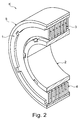
- Figur 2
- zeigt eine perspektivische Schnittansicht der Kupplung der
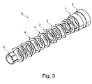
Figur 1 ; und - Figur 3
- zeigt eine perspektivische, explosionsartige Ansicht der Kupplung der
Figuren 1 und2 . -
Figur 1 zeigt eine perspektivische Ansicht einer Kupplung K gemäß einer Ausführungsform der Erfindung. Die Kupplung K wird nachfolgend unter gemeinsamer Bezugnahme auf dieFiguren 1 bis 3 beschrieben. - Die Kupplung K ist als Lamellenkupplung ausgeführt (entweder trocken oder im Ölbad) mit einem zweckmäßig ringförmigen Kupplungstopf 1 (äußeres Kupplungsteil) und einer zweckmäßig ringförmigen Kupplungsnabe 2 (inneres Kupplungsteil). Lamellenpakete 3 und 4, die ebenfalls zweckmäßig ringförmig ausgebildet sind, sind zwischen den Kupplungstopf 1 und die Kupplungsnabe 2 zwischengeschaltet. Das Lamellenpaket 4 ist mit dem Kupplungstopf 1 formschlüssig verbunden und das Lamellenpaket 3 ist mit der Kupplungsnabe 2 formschlüssig verbunden. Werden die Lamellenpakete 3 und 4 gegeneinander gepresst, so findet eine Kraftübertragung vom Kupplungstopf 1 über die Lamellenpakete 3 und 4 auf die Kupplungsnabe 2 statt. Um ein Schalten der Kupplung K zur Herstellung beziehungsweise zum Trennen des Kraftschlusses zu ermöglichen, ist in den formschlüssigen Verbindungen der Lamellenpakete 3 und 4 mit dem Kupplungstopf 1 beziehungsweise der Kupplungsnabe 2 ein radiales Spiel in den formschlüssigen Verbindungen vorhanden.
- Das radiale Spiel kann einen Anlagewechsel der formschlüssig verbundenen Bauteile erzeugen, was zu unerwünschten zum Beispiel schlagenden Geräuschen zwischen den Flanken der formschlüssigen Verbindungen führt. Vor allem der Kupplungstopf 1 strahlt durch transiente Anregung Frequenzanteile ab, die von den Eigenformen, Eigenfrequenzen und den modalen Dämpfungen dieser Eigenformen insbesondere direkt abhängen und mit den entstehenden Körperschallanteilen korrelieren.
- Die Kupplung K ist deshalb mit einem Abstimmring 5 (Abstimmelement) zur Beeinflussung des akustischen Verhaltens der Kupplung K, insbesondere des Kupplungstopfs 1 versehen. Der Abstimmring 5 ummantelt den Kupplungstopf 1 und ist, zweckmäßig direkt und reibungsbehaftet, auf den Kupplungstopf 1 aufgebracht, z. B. mit Vorspannung oder im Wesentlichen vorspannungsfrei.
- Schwingfähige Systeme wie zum Beispiel die Kupplung K können diskret durch eine Matrix von n*m gekoppelten Feder-Masse-Systemen modal beschrieben werden.
- Mittels des Abstimmelements 5 können zuvor-genannte Eigenformen so verstimmt werden, dass ein bevorzugtes Funktions- bzw. Betriebsgeräusch dadurch erreicht wird, dass durch die Bedämpfung der Eigenformen und Frequenzen das akustische Verhalten des Kupplungstopfs 1 besonders gestaltet wird. Im Wesentlichen geschieht diese Gestaltung durch die gezielte Beeinflussung der Impulshaftigkeit und der Modulation einzelner Frequenzgruppen. Weiterhin wird auf die Betonung und Unterdrückung definierter, anwendungsbezogener Frequenzgruppen dadurch abgezielt, dass hierdurch die Schwankungsstärke und die Rauigkeit des emittierten Gesamtgeräusches durch die Beeinflussung der Modalparameter durch Material- und Fügestellungdämpfung (Fügestellendämpfung) sowie Elastizitäts-und Schubmodul des Abstimmelementes 5 eingestellt werden kann.
- Mittels des Abstimmrings 5 können die durch Material- und Fügestellungdämpfung sowie Elastizitäts-und Schubmodul entstehenden Masse-, Steifigkeits- und Dämpfungsmatrizen des Kupplungstopfs 1, unabhängig von seinen Werkstoffeigenschaften, derart beeinflusst werden, dass sich die Modalparameter der Kombination äußerer Kupplungsteil 1 / Abstimmelement 5 bevorzugt dahingehend ändern, dass die psychoakustischen Parameter in Summe zu einem bevorzugten Funktions- und Betriebsgeräusch führen beziehungsweise ein unerwünschtes Geräusch reduziert wird.
- Um dies, insbesondere unabhängig von den Werkstoffeigenschaften des Kupplungstopfs 1 zu erreichen, wird der Abstimmring 5 derart auf den Kupplungstopf 1 aufgebracht, dass die Fügestellendämpfung zwischen dem Abstimmring 5 und dem Kupplungstopf 1 durch den Reibkoeffizienten dazwischen und mittels Tangentialspannung im Kupplungstopf 1 und im Abstimmring 5 einstellbar ist. Das führt zu einer direkten Beeinflussung der Dämpfungsmatrix der Gesamtanordnung. Zusätzlich wird die Dämpfungsmatrix der Anordnung aus äußerem Kupplungsteil 1 und Abstimmring 5 durch Auswahl des Materials (insbesondere Werkstoffes) des Abstimmrings 5 und seiner spezifischen Werkstoffdämpfung bevorzugt gewählt.
- Weiterhin kann die tangentiale Vorspannung des Abstimmrings 5 und elastische Kenngrößen (z. B. E-Modul) des Materials (insbesondere Werkstoffs) des Abstimmrings 5 die Steifigkeitsmatrix der Anordnung äußerer Kupplungsteil 1 / Abstimmring 5 beeinflussen.
- Eine unterschiedliche partielle Masseverteilung und Schichtdicke des Abstimmrings 5 können zur Beeinflussung der Massenmatrix führen.
- Der Abstimmring 5 ist vorzugsweise aus einem Elastomer oder einem duro- oder thermo-plastischen Werkstoff oder beiden ausgeführt. Die Zugabe von füll- und/oder festigkeitssteigernden Zusätzen und/oder Fasern kann ebenfalls gewünschte, vorzugsweise psychoakustische Eigenschaften herbeiführen.
- Es ist möglich, dass die tangentiale Vorspannung z. B. durch einen lose auf den Kupplungstopf 1 aufgelegten Abstimmring 5 z. B. in Form eines Schrumpfschlauchs erfolgt, der durch thermische und/oder chemische Behandlung auf den Kupplungstopf 1 aufgeschrumpft wird. Eine mechanische Vorspannung ist ebenfalls möglich.
- Die Vorspannung des Abstimmrings 5 kann auch den Wert von im Wesentlichen 0 annehmen, so dass nur die Werkstoffdämpfung und/oder die partielle Masseverteilung des Abstimmrings 5 zum Tragen kommt.
- Außerdem kann eine drehzahladaptive Anpassung der psychoakustischen Gestaltung der Funktions- und Betriebsgeräusche dadurch erreicht werden, dass durch Fliehkräfte der Tangentialspannung direkt und/oder indirekt entgegengewirkt wird.
- Alternativ oder ergänzend ist eine temperaturabhängige Anpassung der Geräuschemission über eine Anpassung der thermodynamischen Eigenschaften des Abstimmrings 5 zu erreichen.
- Die Erfindung ist nicht auf die oben beschriebenen bevorzugten Ausführungsformen beschränkt. Vielmehr ist eine Vielzahl von Varianten und Abwandlungen möglich, die ebenfalls von dem Erfindungsgedanken Gebrauch machen und deshalb in den Schutzbereich fallen. Darüber hinaus beansprucht die Erfindung auch Schutz für den Gegenstand und die Merkmale der Unteransprüche unabhängig von den in Bezug genommenen Merkmalen und Ansprüchen.
-
- 1
- Äußeres Kupplungsteil, insbesondere Kupplungstopf
- 2
- Inneres Kupplungsteil, insbesondere Kupplungsnabe
- 3
- Lamellenpaket
- 4
- Lamellenpaket
- 5
- Abstimmelement, insbesondere Abstimmring
- K
- Kupplung, insbesondere Lamellenkupplung
Claims (14)
- Kupplung (K), insbesondere Lamellenkupplung, mit einem äußeren Kupplungsteil (1), vorzugsweise einem Kupplungstopf, und einem inneren Kupplungsteil (2), vorzugsweise einer Kupplungsnabe, dadurch gekennzeichnet, dass ein Abstimmelement (5) zur Beeinflussung des akustischen Verhaltens der Kupplung (K) das äußere Kupplungsteil (1) ummantelt.
- Kupplung (K) nach Anspruch 1, dadurch gekennzeichnet, dass das Abstimmelement (5) auf das äußere Kupplungsteil (1) aufgebracht ist, vorzugsweise reibungsbehaftet.
- Kupplung (K) nach Anspruch 1 oder 2, dadurch gekennzeichnet, dass das Abstimmelement (5) auf das äußere Kupplungsteil (1) so aufgebracht ist, dass eine Fügestellendämpfung zwischen äußerem Kupplungsteil (1) und Abstimmelement (5) durch den Reibkoeffizienten und/oder mittels Tangentialspannung im äußeren Kupplungsteil (1) und Abstimmelement (5) beeinflusst wird.
- Kupplung (K) nach einem der vorhergehenden Ansprüche, dadurch gekennzeichnet, dass das Abstimmelement (5) aus zumindest zwei unterschiedlichen Materialien ausgebildet ist.
- Kupplung (K) nach einem der vorhergehenden Ansprüche, dadurch gekennzeichnet, dass das Abstimmelement (5) zumindest eines von Folgenden aufweist:a) ein Elastomer oder unterschiedliche Elastomere,b) einen duro-plastischen Werkstoff oder unterschiedliche duro-plastische Werkstoffec) einen thermo-plastischen Werkstoff oder unterschiedliche thermo-plastische Werkstoffe.
- Kupplung (K) nach Anspruch 5, dadurch gekennzeichnet, dass in das Abstimmelement (5) zumindest ein Materialzusatz, ein festigkeitssteigernder Zusatz und/oder Fasern eingearbeitet sind.
- Kupplung (K) nach einem der vorhergehenden Ansprüche, dadurch gekennzeichnet, dass das Abstimmelement (5) unterschiedliche Schichtdicken aufweist.
- Kupplung (K) nach einem der vorhergehenden Ansprüche, dadurch gekennzeichnet, dass das Abstimmelement (5) eine partielle Masseverteilung aufweist.
- Kupplung (K) nach einem der vorhergehenden Ansprüche, dadurch gekennzeichnet, dass das Abstimmelement (5) im Wesentlichen vorspannungsfrei auf das äußere Kupplungsteil (1) aufgebracht ist.
- Kupplung (K) nach einem der Ansprüche 1 bis 8, dadurch gekennzeichnet, dass das Abstimmelement (5) mit Vorspannung auf das äußere Kupplungsteil (1) aufgebracht ist.
- Kupplung (K) nach einem der vorhergehenden Ansprüche, dadurch gekennzeichnet, dass das Abstimmelement (5) thermisch und/oder chemisch auf das äußere Kupplungsteil (1) aufgeschrumpft ist.
- Kupplung (K) nach einem der vorhergehenden Ansprüche, dadurch gekennzeichnet, dass das Abstimmelement (5) mechanisch auf das äußere Kupplungsteil (1) vorgespannt ist.
- Kupplung (K) nach einem der vorhergehenden Ansprüche, dadurch gekennzeichnet, dass das Abstimmelement (5) ein Abstimmring ist und vorzugsweise das äußere Kupplungsteil (1) und/oder das innere Kupplungsteil (2) ringförmig ausgebildet sind.
- Kupplung (K) nach einem der vorhergehenden Ansprüche, dadurch gekennzeichnet, dass Lamellenpakete (2, 4) zwischen dem äußeren Kupplungsteil (1) und dem inneren Kupplungsteil (2) angeordnet sind.
Applications Claiming Priority (1)
| Application Number | Priority Date | Filing Date | Title |
|---|---|---|---|
| DE102015013428.0A DE102015013428A1 (de) | 2015-10-15 | 2015-10-15 | Kupplung mit Abstimmelement zur Beeinflussung des akustischen Verhaltens der Kupplung |
Publications (3)
| Publication Number | Publication Date |
|---|---|
| EP3156680A2 true EP3156680A2 (de) | 2017-04-19 |
| EP3156680A3 EP3156680A3 (de) | 2017-04-26 |
| EP3156680B1 EP3156680B1 (de) | 2023-08-16 |
Family
ID=56842583
Family Applications (1)
| Application Number | Title | Priority Date | Filing Date |
|---|---|---|---|
| EP16001881.8A Active EP3156680B1 (de) | 2015-10-15 | 2016-08-26 | Kupplung mit abstimmelement zur beeinflussung des akustischen verhaltens der kupplung |
Country Status (6)
| Country | Link |
|---|---|
| US (1) | US9945429B2 (de) |
| EP (1) | EP3156680B1 (de) |
| CN (1) | CN106979252B (de) |
| BR (1) | BR102016021882B1 (de) |
| DE (1) | DE102015013428A1 (de) |
| RU (1) | RU2725021C2 (de) |
Family Cites Families (29)
| Publication number | Priority date | Publication date | Assignee | Title |
|---|---|---|---|---|
| DE1725998U (de) | ||||
| SU561030A1 (ru) * | 1975-11-26 | 1977-06-05 | Всесоюзный Научно-Исследовательский И Проектно-Конструкторский Институт Редукторостроения (Внииредуктор) | Упруго-предохранительна муфта |
| DE7725998U1 (de) * | 1977-08-22 | 1979-02-15 | Thyssen Industrie Ag, 4300 Essen | Drehelastische, stoss- und schwingungsdaempfende kupplung |
| DE4433467C2 (de) * | 1993-09-28 | 2003-04-17 | Luk Lamellen & Kupplungsbau | Torsionsschwingungsdämpfer |
| US5613586A (en) * | 1994-02-25 | 1997-03-25 | Horton, Inc. | Rotational control apparatus |
| US5611415A (en) * | 1994-02-25 | 1997-03-18 | Horton, Inc. | Rotational control apparatus |
| US5482105A (en) * | 1994-05-12 | 1996-01-09 | General Clutch Corporation | Clutch control for roller shades |
| JP3322015B2 (ja) * | 1994-08-26 | 2002-09-09 | スズキ株式会社 | 摩擦係合装置のハウジング制振構造 |
| CN2206373Y (zh) * | 1994-11-18 | 1995-08-30 | 天津市红光高压阀厂 | 内齿形弹性联轴器 |
| DE19701178C2 (de) * | 1997-01-15 | 2000-12-07 | Umfotec Umformtechnik Gmbh | Lagerring |
| CN1777765B (zh) * | 2003-02-04 | 2012-03-21 | 利滕斯汽车公司 | 曲轴扭矩调节器 |
| DE102004021044A1 (de) * | 2003-05-07 | 2004-11-25 | Luk Lamellen Und Kupplungsbau Beteiligungs Kg | Einrichtung zum Dämpfen von Schwingungen |
| DE102004034813B4 (de) * | 2004-07-19 | 2012-09-06 | Man Truck & Bus Ag | Geräuschoptimierter Mantellüfter |
| RU52178U1 (ru) * | 2005-06-07 | 2006-03-10 | Открытое акционерное общество "АВТОВАЗ" | Акустический моторный стенд для исследовательских и доводочных работ по заглушению шума системы впуска двигателя внутреннего сгорания |
| US20070042916A1 (en) * | 2005-06-30 | 2007-02-22 | Iyer Ramnath N | Methods for improved power transmission performance and compositions therefor |
| DE202007010294U1 (de) * | 2007-07-20 | 2008-11-27 | Wirtgen Gmbh | Baumaschine sowie Schaltkupplung zum Schalten des Kraftflusses |
| JP4797008B2 (ja) * | 2007-09-26 | 2011-10-19 | 本田技研工業株式会社 | 多板クラッチ |
| KR100931445B1 (ko) | 2007-12-20 | 2009-12-11 | 현대자동차주식회사 | 차량의 수동식 클러치의 노이즈 저감 장치 |
| CN201281091Y (zh) * | 2008-07-29 | 2009-07-29 | 梁业华 | 摩托车离合器 |
| RU2011150261A (ru) * | 2009-05-11 | 2013-06-20 | Конинклейке Филипс Электроникс Н.В. | Головка громкоговорителя и конструкция громкоговорителя |
| US20120015768A1 (en) * | 2010-07-13 | 2012-01-19 | Alexander Serkh | Isolating Pulley |
| CN102237745B (zh) * | 2011-07-15 | 2013-08-28 | 广州市瑞翔机电有限公司 | 一种窗帘系统中的电机装置 |
| CN202144839U (zh) | 2011-07-19 | 2012-02-15 | 北京三一电机系统有限责任公司 | 一种联轴器装置 |
| DE102012220732A1 (de) * | 2011-12-07 | 2013-06-13 | Schaeffler Technologies AG & Co. KG | Triebrad für einen Nebenaggregatantrieb |
| DE102012223829A1 (de) * | 2012-12-19 | 2014-06-26 | Zf Friedrichshafen Ag | Gelenkeinrichtung für ein Kraftfahrzeug |
| US9097335B2 (en) * | 2013-07-29 | 2015-08-04 | Gates Corporation | Crankshaft isolating decoupler |
| CN203809534U (zh) | 2014-01-20 | 2014-09-03 | 泰州市永林机械厂 | 一种汽车离合器壳体 |
| US20160084323A1 (en) * | 2014-09-18 | 2016-03-24 | Metaldyne, Llc | Transmission damper |
| CN205401583U (zh) * | 2016-03-09 | 2016-07-27 | 济南弘正科技有限公司 | 一种摩托车离合器 |
-
2015
- 2015-10-15 DE DE102015013428.0A patent/DE102015013428A1/de not_active Withdrawn
-
2016
- 2016-08-26 EP EP16001881.8A patent/EP3156680B1/de active Active
- 2016-09-22 BR BR102016021882-9A patent/BR102016021882B1/pt not_active IP Right Cessation
- 2016-09-30 RU RU2016138697A patent/RU2725021C2/ru active
- 2016-10-12 CN CN201610888472.4A patent/CN106979252B/zh active Active
- 2016-10-14 US US15/294,129 patent/US9945429B2/en active Active
Non-Patent Citations (1)
| Title |
|---|
| None |
Also Published As
| Publication number | Publication date |
|---|---|
| EP3156680A3 (de) | 2017-04-26 |
| EP3156680B1 (de) | 2023-08-16 |
| BR102016021882A2 (pt) | 2017-04-25 |
| BR102016021882B1 (pt) | 2023-01-03 |
| CN106979252B (zh) | 2021-03-05 |
| US9945429B2 (en) | 2018-04-17 |
| RU2725021C2 (ru) | 2020-06-29 |
| RU2016138697A (ru) | 2018-04-02 |
| US20170108053A1 (en) | 2017-04-20 |
| CN106979252A (zh) | 2017-07-25 |
| DE102015013428A1 (de) | 2017-04-20 |
| RU2016138697A3 (de) | 2020-02-26 |
Similar Documents
| Publication | Publication Date | Title |
|---|---|---|
| DE3635702C2 (de) | ||
| EP2406521B1 (de) | Antriebsstrang für hybridantriebe mit torsionsdämpfer und fliehkraftpendel | |
| DE102013213011A1 (de) | Fliehkraftpendeleinrichtung zur Schwingungsisolation | |
| DE10117745A1 (de) | Kupplungsscheibe | |
| DE102019101983A1 (de) | Speichenfedertilger und Verwendung eines Speichenfedertilgers | |
| DE102018113585B4 (de) | Drehschwingungsdämpfer | |
| DE3621997C2 (de) | ||
| DE3825062A1 (de) | Torsionsschwingungsdaempfer | |
| DE102013006098A1 (de) | Bremsbacke für eine Scheibenbremse eines Kraftfahrzeugs | |
| DE102018109266A1 (de) | Drehschwingungsdämpfer | |
| EP3156680B1 (de) | Kupplung mit abstimmelement zur beeinflussung des akustischen verhaltens der kupplung | |
| DE202014003534U1 (de) | Drehschwingungsdämpferanordnung für einen Antriebsstrang | |
| DE102010009411B4 (de) | Drehschwingungstilger | |
| DE10064332C1 (de) | Dämpfungseinrichtung für eine drehelastische Kupplung | |
| DE102004035900A1 (de) | Motorradfelge | |
| DE102014220378A1 (de) | Verfahren zum Auswuchten einer Fliehkraftpendeleinrichtung | |
| DE202015006155U1 (de) | Drehschwingungsdämpfungsanordnung | |
| DE102009007827A1 (de) | Reibbelag | |
| EP0425769B1 (de) | Elastische Kupplung zur Drehmoment-Übertragung | |
| DE102015112877B4 (de) | Schwungrad- und Doppelkupplungsmodul-Baugruppe | |
| DE102016207101A1 (de) | Drehschwingungsdämpfer | |
| DE102020122501A1 (de) | Drehschwingungsdämpfer | |
| DE102015213659A1 (de) | Dichtungsanordnung für eine Dämpferbaugruppe | |
| DE4243323A1 (de) | Schwingungsmotor | |
| DE102018132402A1 (de) | Drehschwingungsdämpfer |
Legal Events
| Date | Code | Title | Description |
|---|---|---|---|
| PUAI | Public reference made under article 153(3) epc to a published international application that has entered the european phase |
Free format text: ORIGINAL CODE: 0009012 |
|
| STAA | Information on the status of an ep patent application or granted ep patent |
Free format text: STATUS: THE APPLICATION HAS BEEN PUBLISHED |
|
| PUAL | Search report despatched |
Free format text: ORIGINAL CODE: 0009013 |
|
| AK | Designated contracting states |
Kind code of ref document: A2 Designated state(s): AL AT BE BG CH CY CZ DE DK EE ES FI FR GB GR HR HU IE IS IT LI LT LU LV MC MK MT NL NO PL PT RO RS SE SI SK SM TR |
|
| AX | Request for extension of the european patent |
Extension state: BA ME |
|
| AK | Designated contracting states |
Kind code of ref document: A3 Designated state(s): AL AT BE BG CH CY CZ DE DK EE ES FI FR GB GR HR HU IE IS IT LI LT LU LV MC MK MT NL NO PL PT RO RS SE SI SK SM TR |
|
| AX | Request for extension of the european patent |
Extension state: BA ME |
|
| RIC1 | Information provided on ipc code assigned before grant |
Ipc: F16D 13/52 20060101ALI20170322BHEP Ipc: F16D 25/0638 20060101AFI20170322BHEP |
|
| STAA | Information on the status of an ep patent application or granted ep patent |
Free format text: STATUS: REQUEST FOR EXAMINATION WAS MADE |
|
| 17P | Request for examination filed |
Effective date: 20171024 |
|
| RBV | Designated contracting states (corrected) |
Designated state(s): AL AT BE BG CH CY CZ DE DK EE ES FI FR GB GR HR HU IE IS IT LI LT LU LV MC MK MT NL NO PL PT RO RS SE SI SK SM TR |
|
| STAA | Information on the status of an ep patent application or granted ep patent |
Free format text: STATUS: EXAMINATION IS IN PROGRESS |
|
| 17Q | First examination report despatched |
Effective date: 20180424 |
|
| RAP1 | Party data changed (applicant data changed or rights of an application transferred) |
Owner name: MAN TRUCK & BUS SE |
|
| REG | Reference to a national code |
Ref country code: DE Ref legal event code: R079 Free format text: PREVIOUS MAIN CLASS: F16D0025063800 Ipc: F16D0013620000 Ref country code: DE Ref legal event code: R079 Ref document number: 502016016014 Country of ref document: DE Free format text: PREVIOUS MAIN CLASS: F16D0025063800 Ipc: F16D0013620000 |
|
| RIC1 | Information provided on ipc code assigned before grant |
Ipc: F16D 13/62 20060101AFI20210118BHEP |
|
| GRAP | Despatch of communication of intention to grant a patent |
Free format text: ORIGINAL CODE: EPIDOSNIGR1 |
|
| STAA | Information on the status of an ep patent application or granted ep patent |
Free format text: STATUS: GRANT OF PATENT IS INTENDED |
|
| INTG | Intention to grant announced |
Effective date: 20230313 |
|
| GRAS | Grant fee paid |
Free format text: ORIGINAL CODE: EPIDOSNIGR3 |
|
| GRAA | (expected) grant |
Free format text: ORIGINAL CODE: 0009210 |
|
| STAA | Information on the status of an ep patent application or granted ep patent |
Free format text: STATUS: THE PATENT HAS BEEN GRANTED |
|
| AK | Designated contracting states |
Kind code of ref document: B1 Designated state(s): AL AT BE BG CH CY CZ DE DK EE ES FI FR GB GR HR HU IE IS IT LI LT LU LV MC MK MT NL NO PL PT RO RS SE SI SK SM TR |
|
| REG | Reference to a national code |
Ref country code: GB Ref legal event code: FG4D Free format text: NOT ENGLISH |
|
| REG | Reference to a national code |
Ref country code: CH Ref legal event code: EP Ref country code: DE Ref legal event code: R096 Ref document number: 502016016014 Country of ref document: DE |
|
| REG | Reference to a national code |
Ref country code: IE Ref legal event code: FG4D Free format text: LANGUAGE OF EP DOCUMENT: GERMAN |
|
| REG | Reference to a national code |
Ref country code: NL Ref legal event code: FP |
|
| REG | Reference to a national code |
Ref country code: SE Ref legal event code: TRGR |
|
| REG | Reference to a national code |
Ref country code: LT Ref legal event code: MG9D |
|
| PG25 | Lapsed in a contracting state [announced via postgrant information from national office to epo] |
Ref country code: GR Free format text: LAPSE BECAUSE OF FAILURE TO SUBMIT A TRANSLATION OF THE DESCRIPTION OR TO PAY THE FEE WITHIN THE PRESCRIBED TIME-LIMIT Effective date: 20231117 |
|
| PG25 | Lapsed in a contracting state [announced via postgrant information from national office to epo] |
Ref country code: IS Free format text: LAPSE BECAUSE OF FAILURE TO SUBMIT A TRANSLATION OF THE DESCRIPTION OR TO PAY THE FEE WITHIN THE PRESCRIBED TIME-LIMIT Effective date: 20231216 |
|
| PG25 | Lapsed in a contracting state [announced via postgrant information from national office to epo] |
Ref country code: RS Free format text: LAPSE BECAUSE OF FAILURE TO SUBMIT A TRANSLATION OF THE DESCRIPTION OR TO PAY THE FEE WITHIN THE PRESCRIBED TIME-LIMIT Effective date: 20230816 Ref country code: PT Free format text: LAPSE BECAUSE OF FAILURE TO SUBMIT A TRANSLATION OF THE DESCRIPTION OR TO PAY THE FEE WITHIN THE PRESCRIBED TIME-LIMIT Effective date: 20231218 Ref country code: NO Free format text: LAPSE BECAUSE OF FAILURE TO SUBMIT A TRANSLATION OF THE DESCRIPTION OR TO PAY THE FEE WITHIN THE PRESCRIBED TIME-LIMIT Effective date: 20231116 Ref country code: LV Free format text: LAPSE BECAUSE OF FAILURE TO SUBMIT A TRANSLATION OF THE DESCRIPTION OR TO PAY THE FEE WITHIN THE PRESCRIBED TIME-LIMIT Effective date: 20230816 Ref country code: LT Free format text: LAPSE BECAUSE OF FAILURE TO SUBMIT A TRANSLATION OF THE DESCRIPTION OR TO PAY THE FEE WITHIN THE PRESCRIBED TIME-LIMIT Effective date: 20230816 Ref country code: IS Free format text: LAPSE BECAUSE OF FAILURE TO SUBMIT A TRANSLATION OF THE DESCRIPTION OR TO PAY THE FEE WITHIN THE PRESCRIBED TIME-LIMIT Effective date: 20231216 Ref country code: HR Free format text: LAPSE BECAUSE OF FAILURE TO SUBMIT A TRANSLATION OF THE DESCRIPTION OR TO PAY THE FEE WITHIN THE PRESCRIBED TIME-LIMIT Effective date: 20230816 Ref country code: GR Free format text: LAPSE BECAUSE OF FAILURE TO SUBMIT A TRANSLATION OF THE DESCRIPTION OR TO PAY THE FEE WITHIN THE PRESCRIBED TIME-LIMIT Effective date: 20231117 Ref country code: FI Free format text: LAPSE BECAUSE OF FAILURE TO SUBMIT A TRANSLATION OF THE DESCRIPTION OR TO PAY THE FEE WITHIN THE PRESCRIBED TIME-LIMIT Effective date: 20230816 |
|
| PG25 | Lapsed in a contracting state [announced via postgrant information from national office to epo] |
Ref country code: PL Free format text: LAPSE BECAUSE OF FAILURE TO SUBMIT A TRANSLATION OF THE DESCRIPTION OR TO PAY THE FEE WITHIN THE PRESCRIBED TIME-LIMIT Effective date: 20230816 |
|
| REG | Reference to a national code |
Ref country code: CH Ref legal event code: PL |
|
| PG25 | Lapsed in a contracting state [announced via postgrant information from national office to epo] |
Ref country code: LU Free format text: LAPSE BECAUSE OF NON-PAYMENT OF DUE FEES Effective date: 20230826 |
|
| PG25 | Lapsed in a contracting state [announced via postgrant information from national office to epo] |
Ref country code: ES Free format text: LAPSE BECAUSE OF FAILURE TO SUBMIT A TRANSLATION OF THE DESCRIPTION OR TO PAY THE FEE WITHIN THE PRESCRIBED TIME-LIMIT Effective date: 20230816 |
|
| PG25 | Lapsed in a contracting state [announced via postgrant information from national office to epo] |
Ref country code: SM Free format text: LAPSE BECAUSE OF FAILURE TO SUBMIT A TRANSLATION OF THE DESCRIPTION OR TO PAY THE FEE WITHIN THE PRESCRIBED TIME-LIMIT Effective date: 20230816 Ref country code: RO Free format text: LAPSE BECAUSE OF FAILURE TO SUBMIT A TRANSLATION OF THE DESCRIPTION OR TO PAY THE FEE WITHIN THE PRESCRIBED TIME-LIMIT Effective date: 20230816 Ref country code: LU Free format text: LAPSE BECAUSE OF NON-PAYMENT OF DUE FEES Effective date: 20230826 Ref country code: ES Free format text: LAPSE BECAUSE OF FAILURE TO SUBMIT A TRANSLATION OF THE DESCRIPTION OR TO PAY THE FEE WITHIN THE PRESCRIBED TIME-LIMIT Effective date: 20230816 Ref country code: EE Free format text: LAPSE BECAUSE OF FAILURE TO SUBMIT A TRANSLATION OF THE DESCRIPTION OR TO PAY THE FEE WITHIN THE PRESCRIBED TIME-LIMIT Effective date: 20230816 Ref country code: DK Free format text: LAPSE BECAUSE OF FAILURE TO SUBMIT A TRANSLATION OF THE DESCRIPTION OR TO PAY THE FEE WITHIN THE PRESCRIBED TIME-LIMIT Effective date: 20230816 Ref country code: CZ Free format text: LAPSE BECAUSE OF FAILURE TO SUBMIT A TRANSLATION OF THE DESCRIPTION OR TO PAY THE FEE WITHIN THE PRESCRIBED TIME-LIMIT Effective date: 20230816 Ref country code: CH Free format text: LAPSE BECAUSE OF NON-PAYMENT OF DUE FEES Effective date: 20230831 Ref country code: SK Free format text: LAPSE BECAUSE OF FAILURE TO SUBMIT A TRANSLATION OF THE DESCRIPTION OR TO PAY THE FEE WITHIN THE PRESCRIBED TIME-LIMIT Effective date: 20230816 |
|
| REG | Reference to a national code |
Ref country code: BE Ref legal event code: MM Effective date: 20230831 |
|
| REG | Reference to a national code |
Ref country code: DE Ref legal event code: R097 Ref document number: 502016016014 Country of ref document: DE |
|
| REG | Reference to a national code |
Ref country code: IE Ref legal event code: MM4A |
|
| PG25 | Lapsed in a contracting state [announced via postgrant information from national office to epo] |
Ref country code: MC Free format text: LAPSE BECAUSE OF FAILURE TO SUBMIT A TRANSLATION OF THE DESCRIPTION OR TO PAY THE FEE WITHIN THE PRESCRIBED TIME-LIMIT Effective date: 20230816 |
|
| PLBE | No opposition filed within time limit |
Free format text: ORIGINAL CODE: 0009261 |
|
| STAA | Information on the status of an ep patent application or granted ep patent |
Free format text: STATUS: NO OPPOSITION FILED WITHIN TIME LIMIT |
|
| PG25 | Lapsed in a contracting state [announced via postgrant information from national office to epo] |
Ref country code: IE Free format text: LAPSE BECAUSE OF NON-PAYMENT OF DUE FEES Effective date: 20230826 |
|
| 26N | No opposition filed |
Effective date: 20240517 |
|
| GBPC | Gb: european patent ceased through non-payment of renewal fee |
Effective date: 20231116 |
|
| PG25 | Lapsed in a contracting state [announced via postgrant information from national office to epo] |
Ref country code: IT Free format text: LAPSE BECAUSE OF NON-PAYMENT OF DUE FEES Effective date: 20230826 Ref country code: IE Free format text: LAPSE BECAUSE OF NON-PAYMENT OF DUE FEES Effective date: 20230826 Ref country code: SI Free format text: LAPSE BECAUSE OF FAILURE TO SUBMIT A TRANSLATION OF THE DESCRIPTION OR TO PAY THE FEE WITHIN THE PRESCRIBED TIME-LIMIT Effective date: 20230816 |
|
| PG25 | Lapsed in a contracting state [announced via postgrant information from national office to epo] |
Ref country code: BE Free format text: LAPSE BECAUSE OF NON-PAYMENT OF DUE FEES Effective date: 20230831 |
|
| PG25 | Lapsed in a contracting state [announced via postgrant information from national office to epo] |
Ref country code: GB Free format text: LAPSE BECAUSE OF NON-PAYMENT OF DUE FEES Effective date: 20231116 |
|
| REG | Reference to a national code |
Ref country code: AT Ref legal event code: MM01 Ref document number: 1600334 Country of ref document: AT Kind code of ref document: T Effective date: 20230826 |
|
| PG25 | Lapsed in a contracting state [announced via postgrant information from national office to epo] |
Ref country code: AT Free format text: LAPSE BECAUSE OF NON-PAYMENT OF DUE FEES Effective date: 20230826 |
|
| PG25 | Lapsed in a contracting state [announced via postgrant information from national office to epo] |
Ref country code: GB Free format text: LAPSE BECAUSE OF NON-PAYMENT OF DUE FEES Effective date: 20231116 Ref country code: AT Free format text: LAPSE BECAUSE OF NON-PAYMENT OF DUE FEES Effective date: 20230826 |
|
| PG25 | Lapsed in a contracting state [announced via postgrant information from national office to epo] |
Ref country code: BG Free format text: LAPSE BECAUSE OF FAILURE TO SUBMIT A TRANSLATION OF THE DESCRIPTION OR TO PAY THE FEE WITHIN THE PRESCRIBED TIME-LIMIT Effective date: 20230816 |
|
| PG25 | Lapsed in a contracting state [announced via postgrant information from national office to epo] |
Ref country code: BG Free format text: LAPSE BECAUSE OF FAILURE TO SUBMIT A TRANSLATION OF THE DESCRIPTION OR TO PAY THE FEE WITHIN THE PRESCRIBED TIME-LIMIT Effective date: 20230816 |
|
| PG25 | Lapsed in a contracting state [announced via postgrant information from national office to epo] |
Ref country code: CY Free format text: LAPSE BECAUSE OF FAILURE TO SUBMIT A TRANSLATION OF THE DESCRIPTION OR TO PAY THE FEE WITHIN THE PRESCRIBED TIME-LIMIT; INVALID AB INITIO Effective date: 20160826 |
|
| PG25 | Lapsed in a contracting state [announced via postgrant information from national office to epo] |
Ref country code: HU Free format text: LAPSE BECAUSE OF FAILURE TO SUBMIT A TRANSLATION OF THE DESCRIPTION OR TO PAY THE FEE WITHIN THE PRESCRIBED TIME-LIMIT; INVALID AB INITIO Effective date: 20160826 |
|
| PGFP | Annual fee paid to national office [announced via postgrant information from national office to epo] |
Ref country code: NL Payment date: 20250825 Year of fee payment: 10 |
|
| PGFP | Annual fee paid to national office [announced via postgrant information from national office to epo] |
Ref country code: DE Payment date: 20250827 Year of fee payment: 10 |
|
| PGFP | Annual fee paid to national office [announced via postgrant information from national office to epo] |
Ref country code: FR Payment date: 20250825 Year of fee payment: 10 |
|
| PGFP | Annual fee paid to national office [announced via postgrant information from national office to epo] |
Ref country code: SE Payment date: 20250825 Year of fee payment: 10 |
|
| PG25 | Lapsed in a contracting state [announced via postgrant information from national office to epo] |
Ref country code: TR Free format text: LAPSE BECAUSE OF FAILURE TO SUBMIT A TRANSLATION OF THE DESCRIPTION OR TO PAY THE FEE WITHIN THE PRESCRIBED TIME-LIMIT Effective date: 20230816 |