EP3156377A1 - Wolfram-haltiger formdorn zur glasformung - Google Patents
Wolfram-haltiger formdorn zur glasformung Download PDFInfo
- Publication number
- EP3156377A1 EP3156377A1 EP16192984.9A EP16192984A EP3156377A1 EP 3156377 A1 EP3156377 A1 EP 3156377A1 EP 16192984 A EP16192984 A EP 16192984A EP 3156377 A1 EP3156377 A1 EP 3156377A1
- Authority
- EP
- European Patent Office
- Prior art keywords
- glass
- tungsten
- forming
- iridium
- mandrel
- Prior art date
- Legal status (The legal status is an assumption and is not a legal conclusion. Google has not performed a legal analysis and makes no representation as to the accuracy of the status listed.)
- Granted
Links
Images


Classifications
-
- C—CHEMISTRY; METALLURGY
- C03—GLASS; MINERAL OR SLAG WOOL
- C03B—MANUFACTURE, SHAPING, OR SUPPLEMENTARY PROCESSES
- C03B23/00—Re-forming shaped glass
- C03B23/04—Re-forming tubes or rods
- C03B23/043—Heating devices specially adapted for re-forming tubes or rods in general, e.g. burners
-
- A—HUMAN NECESSITIES
- A61—MEDICAL OR VETERINARY SCIENCE; HYGIENE
- A61M—DEVICES FOR INTRODUCING MEDIA INTO, OR ONTO, THE BODY; DEVICES FOR TRANSDUCING BODY MEDIA OR FOR TAKING MEDIA FROM THE BODY; DEVICES FOR PRODUCING OR ENDING SLEEP OR STUPOR
- A61M5/00—Devices for bringing media into the body in a subcutaneous, intra-vascular or intramuscular way; Accessories therefor, e.g. filling or cleaning devices, arm-rests
- A61M5/178—Syringes
-
- C—CHEMISTRY; METALLURGY
- C03—GLASS; MINERAL OR SLAG WOOL
- C03B—MANUFACTURE, SHAPING, OR SUPPLEMENTARY PROCESSES
- C03B23/00—Re-forming shaped glass
- C03B23/04—Re-forming tubes or rods
- C03B23/045—Tools or apparatus specially adapted for re-forming tubes or rods in general, e.g. glass lathes, chucks
-
- C—CHEMISTRY; METALLURGY
- C03—GLASS; MINERAL OR SLAG WOOL
- C03B—MANUFACTURE, SHAPING, OR SUPPLEMENTARY PROCESSES
- C03B23/00—Re-forming shaped glass
- C03B23/04—Re-forming tubes or rods
- C03B23/049—Re-forming tubes or rods by pressing
-
- C—CHEMISTRY; METALLURGY
- C03—GLASS; MINERAL OR SLAG WOOL
- C03B—MANUFACTURE, SHAPING, OR SUPPLEMENTARY PROCESSES
- C03B23/00—Re-forming shaped glass
- C03B23/04—Re-forming tubes or rods
- C03B23/055—Re-forming tubes or rods by rolling
-
- C—CHEMISTRY; METALLURGY
- C03—GLASS; MINERAL OR SLAG WOOL
- C03B—MANUFACTURE, SHAPING, OR SUPPLEMENTARY PROCESSES
- C03B23/00—Re-forming shaped glass
- C03B23/04—Re-forming tubes or rods
- C03B23/09—Reshaping the ends, e.g. as grooves, threads or mouths
- C03B23/092—Reshaping the ends, e.g. as grooves, threads or mouths by pressing
-
- C—CHEMISTRY; METALLURGY
- C03—GLASS; MINERAL OR SLAG WOOL
- C03C—CHEMICAL COMPOSITION OF GLASSES, GLAZES OR VITREOUS ENAMELS; SURFACE TREATMENT OF GLASS; SURFACE TREATMENT OF FIBRES OR FILAMENTS MADE FROM GLASS, MINERALS OR SLAGS; JOINING GLASS TO GLASS OR OTHER MATERIALS
- C03C3/00—Glass compositions
- C03C3/04—Glass compositions containing silica
- C03C3/076—Glass compositions containing silica with 40% to 90% silica, by weight
- C03C3/089—Glass compositions containing silica with 40% to 90% silica, by weight containing boron
- C03C3/091—Glass compositions containing silica with 40% to 90% silica, by weight containing boron containing aluminium
-
- C—CHEMISTRY; METALLURGY
- C22—METALLURGY; FERROUS OR NON-FERROUS ALLOYS; TREATMENT OF ALLOYS OR NON-FERROUS METALS
- C22C—ALLOYS
- C22C5/00—Alloys based on noble metals
- C22C5/04—Alloys based on a platinum group metal
-
- A—HUMAN NECESSITIES
- A61—MEDICAL OR VETERINARY SCIENCE; HYGIENE
- A61M—DEVICES FOR INTRODUCING MEDIA INTO, OR ONTO, THE BODY; DEVICES FOR TRANSDUCING BODY MEDIA OR FOR TAKING MEDIA FROM THE BODY; DEVICES FOR PRODUCING OR ENDING SLEEP OR STUPOR
- A61M2207/00—Methods of manufacture, assembly or production
-
- A—HUMAN NECESSITIES
- A61—MEDICAL OR VETERINARY SCIENCE; HYGIENE
- A61M—DEVICES FOR INTRODUCING MEDIA INTO, OR ONTO, THE BODY; DEVICES FOR TRANSDUCING BODY MEDIA OR FOR TAKING MEDIA FROM THE BODY; DEVICES FOR PRODUCING OR ENDING SLEEP OR STUPOR
- A61M2207/00—Methods of manufacture, assembly or production
- A61M2207/10—Device therefor
Definitions
- the invention generally relates to the production of glass products. More particularly, the invention relates to a mold comprising a tungsten-containing mandrel, a method and apparatus for hot-forming glass.
- the glass products obtained in this way can be used, for example, as pharmaceutical packaging.
- hot forming is an essential process step.
- the process of hot forming usually comprises several successive heating and forming processes, with which, starting from tube glass bodies, the desired final geometry is created.
- Hollow-shaped glass products which are to be used in the medical field are usually subject to very high requirements with respect to possible impurities which can result from the hot forming. This results in very high demands on the molds used in the hot forming. These high requirements relate in particular to the materials used for the molds.
- a cone is usually formed using a molding tool comprising a mandrel. The material used for the forming mandrel plays a central role.
- metallic forming materials can be used as the mandrel material.
- Pure tungsten or tungsten alloys have a high thermomechanical strength, which is very advantageous especially for small material cross sections. This is the case, for example, with mandrels with a diameter of less than 0.5 mm to about 1 mm. That's why Form mandrels comprising tungsten or tungsten alloys in the contact region with the glass to be formed advantageous.
- the forming mandrel heats up to temperatures of about 800 ° C to 900 ° C during hot forming. Due to the low cycle times, the material is subject to frequent and rapid temperature changes. The influence of temperature, glass evaporation products, air, moisture and the tribological load of the pressed, doughy glass during the hot forming can therefore cause a material removal on the mandrel.
- This material removal of the mandrel, in particular in the contact area with the glass precursor to be formed, is generally undesirable and leads to a change in the outer geometry or a reduction of the diameter of the mandrel, wherein the decrease in the diameter is also often not uniformly axially pronounced.
- This material removal has several other negative effects.
- the removal of material means that the specified target dimensions for the shaping are less and less adhered to over time as a result of the change in the outer geometry of the mandrel, and the required channel dimensions can thus only be maintained for a limited period of time.
- the service life of the mandrel is thus relatively low and / or additional effort for subsequent adjustments is required.
- the removed material can reach the interior of the glass product being formed. For example, the removal of material during the cone formation of syringes can reach the so-called cone channel.
- mandrel which is free of tungsten and comprises graphite as an essential material. Further, the mandrel may comprise other materials such as silicon carbide or zirconium carbide and is thus free of tungsten.
- WO 2012/039705 A2 proposed a forming mandrel comprising a protective layer as a support layer.
- the base material can be tungsten-containing.
- a neutral glass own material or a glass are proposed, which is a part of the glass to be formed, in order to exclude foreign impurities.
- such coatings have some wear, so that the adverse effect of material removal of the mandrel can hardly be prevented. As a result, the service life of such a mandrel is rather low. Furthermore, due to the high mechanical stress, cracking of the layer material or even spalling of layer constituents may occur, so that the service life of the forming mandrel is further reduced.
- tungsten in the interior of the formed part is not a major drawback, as long as the tungsten content remains within a predetermined range or does not exceed a tolerable limit.
- the introduction of undesirable impurities, in particular of tungsten, into the glass product to be formed by the molding tool, in particular by the forming mandrel, is intended to remain within a predetermined framework.
- the interior or the Inner cone of the formed glass product does not exceed a predetermined limit of contamination by the mold, in particular by the mandrel.
- the mold in particular the forming mandrel, should have a long service life.
- the material removal should be prevented as possible, so that a particularly long service life can be achieved with constant quality without additional adjustment effort.
- the invention relates to a molding tool for reshaping hollow body glass precursors, comprising a molding mandrel for reshaping at least a portion of a heated region of the glass precursor.
- the forming mandrel is formed from an alloy which has at least one first temperature-stable core material.
- it is a massive mandrel to achieve the greatest possible stability.
- core material is understood in the context of this document, the base material or base material of the mandrel, from which this is made.
- a core material of the mandrel is particularly suitable a material which has a high heat resistance and a high modulus of elasticity, so that it is suitable for the mechanical stresses even at temperatures in the range of 400 ° C or more. Furthermore, it should be resistant to acids and glass evaporation products such as borates and have an oxidation resistance in air up to 400 ° C to avoid material removal during or by the hot forming processes for forming hollow body glass precursors.
- the core material is therefore selected from the group of precious metals, in particular the platinum group elements.
- the core material may also comprise an alloy.
- a suitable core material is the precious metals or their alloys, for example platinum.
- the forming mandrel has a further alloying element. This is selected from the group comprising tungsten, zirconium, rhodium, molybdenum or rhenium.
- mandrels comprising platinum group element alloys are also very suitable as molds, in particular as core material for a mandrel, since they have a high mechanical strength.
- the further alloying element tungsten, zirconium, rhodium, molybdenum or rhenium can significantly improve the mechanical and structural behavior of the mandrel.
- the mechanical and structural improvement of the mandrel is particularly advantageous if the material iridium is selected as the core material.
- the inner region in particular the inner cone of the reshaped glass product, can therefore be kept virtually free of impurities, in particular free of contaminants with tungsten, even though the mandrel has tungsten components.
- the core material of the mandrel may include iridium, palladium, platinum, rhodium, rhenium and / or ruthenium or an alloy comprising iridium, palladium, platinum, rhodium, rhenium and / or ruthenium.
- the core material comprises at least 20 weight percent platinum or an alloy having at least 20 weight percent platinum.
- the core material comprises at least 5% by weight of rhodium or an alloy with at least 5% by weight of rhodium.
- the core material comprises a platinum-rhodium alloy with at least 20% by weight of platinum, preferably 25% by weight of platinum and particularly preferably 30% by weight of platinum and at least 5% by weight of rhodium, preferably at least 7% by weight of rhodium and more preferably at least 10% by weight of rhodium.
- the core material comprises a platinum-nickel alloy having at least 5 wt% nickel.
- the core material comprises a platinum-iridium alloy having at least 5 wt% iridium, preferably at least 10 wt% iridium, and more preferably at least 20 wt% iridium.
- the core material comprises at least 20% by weight of iridium, preferably at least 50% by weight of iridium, more preferably at least 70% by weight of iridium and most preferably at least 90% by weight of iridium as the alloying element.
- alloying elements such as tungsten, zirconium, rhodium, molybdenum or rhenium can significantly improve the mechanical and structural behavior of the alloy for the forming mandrel.
- the scope of these alloying elements is advantageously in a range of at least 0.1 wt .-%, preferably of at least 0.3 wt .-%, more preferably 0.5 wt .-% and most preferably at least 0.9 wt. -% and at most 10 wt .-%, preferably at most 6 wt .-% and particularly preferably at most 5 wt .-%.
- iridium is selected as the core material and tungsten as the alloying element.
- Iridium or high-iridium-containing alloys have a very high hardness, which is given on the one hand by the material as such, but can also be achieved by strain hardening in the production. Due to the high recrystallization temperature of iridum, this strength or hardness is largely retained even during use at temperatures around 800 ° C. or 900 ° C., as can occur during hot forming.
- Tungsten is characterized by a high resistance to acids such as HF and HCl and is only slightly attacked by sulfuric acid. Furthermore, it has a good oxidation resistance in air up to 400 ° C. In addition, a high heat resistance and a high modulus of elasticity are favorable for use as an alloy material for a mandrel.
- tungsten as an alloying element have a positive influence on the strength of the mandrel.
- the very low levels of tungsten are at a weight of from about 0.01 wt .-%.
- a material for the mandrel which is an iridium-tungsten alloy with at least 0.01 wt .-%, 0.05 wt .-%, 0.1 wt .-%, preferably at least 0.3 wt. -%, more preferably at least 0.5 wt .-% and most preferably at least 1 wt .-% tungsten comprises. It is furthermore advantageous if the tungsten content is at most 10% by weight, preferably at most 6% by weight and particularly preferably at most 5% by weight.
- the most suitable material for the mandrel may include, for example, an iridium-tungsten alloy having 0.96 wt%, 1.92 wt%, or 3.84 wt% tungsten.
- Such a material has an increased tensile strength and a reduced elongation at break.
- an iridium-tungsten alloy with 0.96 wt.% Tungsten has about a yield strength of 16.271 kN / cm 2 .
- the tensile strength is 39.989 kN / cm 2 and the elongation at break is 16.823 kN / cm 2 .
- iridium Compared to the precious metals platinum and rhodium, iridium has the highest volatility in oxygen-containing atmosphere at elevated temperature.
- the formation of iridium oxides IrO 2 and IrO 3 takes place at temperatures above about 900 ° C. These oxides are volatile, sublimating above about 1000 ° C.
- a tungsten content of an iridium-tungsten alloy between 1% by weight and 3% by weight can significantly reduce the mass loss over time compared to pure iridium. Surprisingly, therefore, such an iridium-tungsten alloy on the one hand leads to a very long service life, on the other hand, however, due to the very low time mass loss to a very low input of tungsten in the inner region or the cone channel of the reprocessed glass precursor.
- iridium alloys with an alloying addition of tungsten for use as a shaping mandrel in the hot shaping of the cone channel are particularly suitable.
- Such iridium-tungsten alloys can be made pyrometallurgically.
- the shaping process of the mandrel can be done by wire drawing, wherein a grinding process can be followed to improve the surface.
- the mandrel is formed of an alloy having at least one first thermally stable core material and at least one further alloying element, wherein the core material comprises at least 50 wt .-% and is selected from the group of precious metals, in particular of the platinum group elements, and wherein the further alloying element selected is selected from the group comprising tungsten, zirconium, rhodium, molybdenum and / or ruthenium or rhenium.
- a portion of the surface of the mandrel may be in direct contact with the glass precursor.
- the apparatus may include a burner for local heating, further comprising rotation means for rotating the mold and the glass precursor relative to one another.
- the molding tool may further comprise a roller pair which is arranged so that the rollers of the roller pair on the surface of a by means of the rotation device in Unroll rotated offset glass precursor, wherein the laser light is a lying between the rollers area on the circumference of the glass precursor is illuminated.
- the device may also comprise a local heating laser in another embodiment.
- the molding tool is preferably designed such that a surface region of the portion of the glass precursor to be reshaped is not covered by the molding tool, wherein the laser or an optics connected downstream of the laser is arranged so that the laser light is not covered by the molding tool during the forming Area is irradiated, and wherein a control device is provided which drives the laser, so that at least temporarily the glass precursor is heated during the deformation by the laser light
- a laser In order to heat the glass of a glass precursor to be formed in the device, a laser is used which emits light of a wavelength for which the glass of the glass precursor is at most partially transparent, so that the light is at least partially absorbed in the glass.
- the molding tool according to the invention is particularly suitable for the low-contamination production of pharmaceutical packaging from glass.
- the invention also encompasses a syringe made of glass, which is produced or producible by a method as described above, and which, especially in the inner region or in the area of the formed inner cone, has only very small impurities, in particular only very small tungsten impurities.
- a glass syringe produced by means of the above-mentioned method or by means of the abovementioned molding tool can therefore have a low content of tungsten within the hollow space.
- the content of tungsten can be determined with the neutron activation analysis (NAA).
- NAA neutron activation analysis
- the atomic nuclei of the sample also referred to as analyte nuclei, interact with the neutrons and, depending on the nature of the nuclear reaction, various products may be formed.
- This process can be carried out in a research reactor or with the help of another neutron source.
- the resulting activation products can be radioactive and then decay with their characteristic half-life. Both activation and decay releases radiation with also characteristic energies that can be used for analysis.
- Syringes produced according to the invention have a very low tungsten content.
- a detection limit of 3 ng which can be achieved by conventional chemical analysis methods, no tungsten components can be detected.
- the detection limit is significantly lower, for example from 0.03 ng to 0.006 ng.
- a tungsten content of about 0.006 ng per syringe could be determined.
- the content of tungsten of the syringe is> 0, which is due to a, albeit very small, wear of the mandrel and which was determined after a cycle of 100,000 transformations. Based on the wear, an impurity is calculated a syringe by a forming process according to the invention, which is in a range of 0.01 to 0.03 ng / syringe.
- the tungsten content of a syringe is therefore> 0 ng,> 0.006 ng,> 0.01 ng,> 0.03 ng.
- the content of tungsten within the cavity is at most 100 ng, at most 50 ng, at most 10 ng, preferably at most 1 ng and particularly preferably at most 0.1 ng per syringe.
- the detection of tungsten contamination is carried out by means of an aqueous extraction method, wherein the inner volume of the syringe is washed out with purified water.
- the filling volume corresponds to the intended filling volume of the syringe. It is worked at elevated temperature (typically 50 ° C to about 100 ° C) and over a period of 4 days.
- elevated temperature typically 50 ° C to about 100 ° C
- the chemical detection of tungsten takes place in the eluate by means of ICP-MS.
- Another advantage of the invention is the fact that it can be dispensed with a coating of the mandrel in the contact area and thus a difference in the expansion behavior between the core material and the coating does not lead to a low toothing, thus the risk of spalling of external components of the mandrel can be largely reduced. At the same time, the risk of cracking is minimized.
- the long service life of the mandrel allows consistently high quality production of the formed glass product without the need for frequent, additional adjustment operations on the forming apparatus.
- a particularly high quality of dimensional compliance is given because the material removal of Fordorns is reduced.
- a narrow tolerance field with respect to the geometry of the glass product can be maintained.
- Another major advantage is that significantly less particles are deposited in the contact area with the glass precursor to be formed, for example in the area of contact with the cone channel of a syringe, due to the lower corrosion wear. At the same time, significantly fewer volatile tungsten components are introduced into the interior of the hollow-body-shaped glass product, for example into the interior of the syringe. The chemically analytically detectable tungsten content is thus significantly reduced.
- the molding tool according to the invention in particular the molding mandrel according to the invention, is particularly suitable for use in the hot forming of glass products which are used as pharmaceutical packaging.
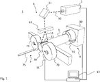
- FIG. 1 an embodiment of an apparatus 1 for carrying out the method according to the invention is shown.
- the designated as a whole by the reference numeral 1 device of in Fig. 1 shown embodiment is designed for forming glass precursors in the form of tube glasses 3.
- the device is used for the production of glass syringe bodies, with the in Fig. 1 shown elements of the device 1 is formed from the tube glass of the cone of the syringe body.
- the production of the cone from the tube glass by means of the device 1 is based on locally heating a region of a tube glass 3, here its end 30, above its softening point and forming at least one section of the heated end with at least one forming tool.
- the local heating device comprises a laser 5 which emits light of a wavelength for which the glass of the tube glass 3 is at most partially transparent, so that the light is at least partially absorbed in the glass.
- Fig. 1 it will be appreciated that it is also possible to use other local heating devices typically used in the hot forming of glass as shown in FIG. 5 for locally heating a hollow glass preform.
- This can also be, for example, burners, such as gas burners.
- burners such as gas burners.
- a detailed description is omitted here.
- the laser beam 50 after Fig. 1 is directed by means of an optic 6 on the tube glass 3.
- the mold 7 and the glass precursor 3 are rotated relative to one another by means of a rotation device 9.
- the rotation device 9 comprises a drive 90 with chuck 91, with which the tube glass 3 is held. It would also be conceivable a reverse configuration in which the tube glass is held and rotates the mold 7 to the tube glass.
- the molding tool 7 comprises in the in Fig. 1 shown embodiment, two rollers 70, 71, which roll on rotation of the tube glass 3 on the surface thereof.
- a forming mandrel 75 is provided as part of the molding tool 7. This mandrel 75 is inserted into the opening of the tube glass 3 at the end 30 to be formed. By means of the forming mandrel 75 of the cone channel of the syringe body is formed. The mandrel 75 may be rotatably supported to rotate together with the tube glass 3. It is also possible to let the rotating glass slide over the retained mandrel.
- the molding tool is designed such that a surface region of the section of the tube glass to be formed is not covered by the molding tool, so that the laser light is irradiated during the deformation to the area not covered by the molding tool by means of the laser 6 connected downstream of the optical system. Specifically, the laser light illuminates a region 33 located between the rollers 70, 71 on the circumference of the tube glass 3.
- a control device 13 controls the forming process.
- the laser 5 is controlled such that, at least temporarily, the tube glass 3 is heated during the deformation by the laser light.
- the optics 6 of in Fig. 1 shown device 1 comprises a deflection mirror 61, and a cylindrical lens 63rd
- the laser beam 50 is widened along the axial direction of the tube glass 3 to form a fan beam 51, so that the area illuminated by the laser light 33 is correspondingly stretched in the axial direction of the tube glass 3. Since the tube glass 3 rotates while the laser light is irradiated, the radiated power is circumferentially distributed on the tube glass, so that a cylindrical portion, or regardless of the shape of the glass precursor generally a portion in the axial direction along the axis of rotation is heated.
- This section has a length that is preferably at least as large as the section to be reshaped. The latter has a length that is essentially determined by the width of the rollers.
- a diffractive optical element may also advantageously be used.
- the molding process is controlled by the controller 13.
- the controller 13 controls the laser power.
- the movement of the molds 70, 71, 75 is controlled.
- the rotation device 9 in particular the rotational speed of the drive 90, possibly also the opening and closing of the chuck 91.
- radiation power of less than 1 kilowatt is generally sufficient for the laser 5 to ensure rapid heating to the softening temperature. After reaching the intended temperature for hot forming then the laser power can be reduced by the control device 1, so that the incident laser power only compensates for the cooling. In the production of syringe bodies generally enough power between 30 and 100 watts.
- the regulation of the laser power can be carried out in particular also based on the temperature of the tube glass 3.
- a control process can be implemented in the control device 13, which regulates the laser power based on the measured temperature by a temperature measuring device to set a predetermined temperature or a predetermined temperature / time profile on the glass precursor.
- a temperature measuring device is in the in Fig. 1 a pyrometer 11 is provided, which measures the heat radiation of the glass tube at its heated end 31 by the laser 5. The measured values are fed to the control device 13 and used in the control process to set the desired temperature.
- Fig. 1 shows is that the laser light does not directly heat the molds.
- the dies are generally not heated more than in a burner previously heated process.
- less heat energy is generated in this way and this heat energy also introduced more targeted in the glass precursor.
- the total heating of the entire device and thus resulting among other things by thermal expansion Einlaufpreheate be reduced.
- a preferred glass for the manufacture of syringe bodies is borosilicate glass.
- Low-alkali borosilicate glass is particularly preferred, in particular with an alkali content of less than 10 percent by weight.
- Borosilicate glass is generally well suited due to the typically high thermal shock resistance. This is favorable in order to be able to realize fast heat-up ramps in the fast process times, as can be achieved with the invention.
- a suitable low-alkali borosilicate glass has the following constituents in percent by weight: SiO 2 75% by weight B 2 O 3 10.5% by weight Al 2 O 3 5% by weight Na 2 O 7% by weight CaO 1.5% by weight
- a transmission spectrum of the glass shows Fig. 2 ,
- the specified transmission values refer to a glass thickness of one millimeter. Based on Fig. 2 It can be seen that the transmission of the glass decreases at wavelengths above 2.5 microns. Above 5 microns, the glass is practically opaque even with very thin glass thicknesses.
- Fig. 2 The decrease in transmission in the wavelength range above 2.5 microns, as shown, does not significantly depend on the exact composition of the glass. Thus, with similar transmission properties, the contents of preferred borosilicate glasses described above may vary by as much as 25% of the indicated value. Furthermore, of course, other glasses can be used in addition to borosilicate glass. If these are at most partially transparent at the wavelength of the laser, a laser source can be used for heating.
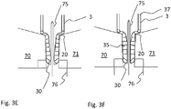
- FIGS. 3A to 3F show schematically with the help of sectional views a simulation of a forming process according to the invention for forming a syringe cone from a tube 3 for the production of a syringe body.
- the sections of the illustrations run along the center axis of the tube glass 3, around which the tube glass is rotated. Also visible are the rollers 70, 71 and the forming mandrel 75.
- the drawn in the sectional views of the tube glass initially perpendicular to the center axis of the tube glass lines 20 mark imaginary boundary lines of axial sections of the tube glass 3. Based on these lines, the flow of material during the forming is identified.
- the mandrel 75 protrudes from a foot 76, which serves to form the front cone surface of the syringe.
- the foot 76 is perpendicular to the viewing direction of the Figs. 3A to 3F flat formed component.
- the foot is rotated 90 ° about the longitudinal axis of the forming mandrel 75 so that the foot 76 fits between the rollers 70, 71.
- the overlap of rollers 70, 71 and foot 76 as they descend Fig. 3C can be seen, so does not actually occur.
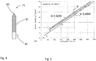
- a portion of a forming mandrel 75 is shown in plan view. Starting from the tip 80 of the forming mandrel 75, a tip-adjacent region 81 of the forming mandrel 75 is marked, in which the forming mandrel 75 comes into contact with the glass precursor during the forming process. A portion 82 is provided for holding the mandrel 75.
- the forming mandrel 75 is formed from an alloy which has at least one first temperature-stable core material.
- the core material is thus the base or base material of the forming mandrel 75 and is selected from the group of noble metals, in particular of the platinum group elements. Accordingly, it is a massive Forming mandrel, at least in that area 81, which serves for the forming.
- the forming mandrel 75 is monolithic.
- the core material is a noble metal, preferably platinum or iridium, or a corresponding platinum or iridium alloy.
- the core material of the mandrel 75 may include iridium and / or platinum, palladium, rhodium, rhenium and / or ruthenium or a corresponding alloy.
- the forming mandrel 75 has a further alloying element.
- This is selected from the group comprising tungsten, zirconium, rhodium, molybdenum or rhenium.
- the scope of these alloying elements is advantageously in a range of at least 0.1 wt .-%, preferably of at least 0.3 wt .-%, more preferably 0.5 wt .-% and most preferably at least 0.9 wt. -% and at most 10 wt .-%, preferably at most 6 wt .-% and particularly preferably at most 5 wt .-%.
- the core material of the mandrel 75 comprises at least 20% by weight of platinum or an alloy containing at least 20% by weight of platinum.
- the core material comprises at least 5% by weight of rhodium or an alloy with at least 5% by weight of rhodium.
- the core material comprises a platinum-rhodium alloy having at least 20% by weight of platinum and at least 5% by weight of rhodium.
- the core material comprises a platinum-nickel alloy having at least 5 wt% nickel.
- the core material comprises a platinum-iridium alloy having at least 5% by weight, preferably at least 10% by weight and more preferably at least 20% by weight of iridium.
- the core material comprises at least 20% by weight, preferably at least 50% by weight, particularly preferably at least 70% by weight and very particularly preferably at least 90% by weight of iridium as alloying element.
- 75 iridium is selected as the core material for the mandrel and tungsten as an alloying element.
- Very suitable for forming a tubular glass of borosilicate glass with a forming tool 1 as described above is a material for the forming mandrel 75, which is an iridium-tungsten alloy having at least 0.01 wt%, 0.05 wt%, 0 , 1 wt .-%, preferably at least 0.3 wt .-%, more preferably at least 0.5 wt .-% and most preferably at least 1 wt .-% tungsten comprises. It is furthermore advantageous if the tungsten content is at most 10% by weight, preferably at most 6% by weight and particularly preferably at most 5% by weight.
- a particularly suitable forming mandrel 75 comprises an iridium-tungsten alloy having 0.96 wt%, 1.92 wt%, or 3.84 wt% tungsten.
- the comparatively high hardness and the high recrystallization temperature of iridum have a very positive effect on the service life of the forming mandrel 75 when forming borosilicate glass. This also allows forming operations at temperatures above 800 ° C or above 900 ° C. This is further favored by the high acid resistance of tungsten.
- the mandrel 75 showed no tendency to crack on the surface or other signs of wear even after very many processing cycles or forming processes, such as between 8,000 and 10,000 cycles.
- Glass syringes, preferably borosilicate glass, formed by means of the above molding tool had a very low tungsten content within the reshaped cavity.
- Syringes may be reshaped with mandrel 75 having a tungsten content within the syringe cavity of less than 50 ng, preferably less than 30 ng, more preferably less than 10 ng per syringe.
- the tungsten content within the cavity of a syringe formed with the mandrel 75 is between 1 and 10 ng per syringe, preferably between 1 and 5 ng per syringe, and more preferably between 1 and 3 ng.
- Fig. 5 is an overview of the mass loss of various iridium-tungsten alloys at 1,000 ° C indicated (source: Liu, Inouye, Dec. 1976, Oak Ridge National Labaratory, Tennesee ). In the overview are on the ordinate axis times in hours and on the abscissa axis, the weight change in 10 -2 g / cm 2 .
- iridium-tungsten alloy is characterized by a low reactivity with respect to the glass constituents.
- iridium has as a noble metal compared to the glass evaporation products, such as alkali oxides or boron oxides, only an undergerodnete reactivity, whereby the corrosion is largely suppressed.
- the impregnation entry into the formed glass product is very small and hardly measurable chemically analytically.
- the molding tool according to the invention in particular the shaping mandrel 75 according to the invention, accordingly bring with it numerous advantages which make the molding tool appear particularly suitable for the production of low-tungsten pharmaceutical packagings, in particular syringes.
Landscapes
- Chemical & Material Sciences (AREA)
- Engineering & Computer Science (AREA)
- Materials Engineering (AREA)
- Organic Chemistry (AREA)
- Health & Medical Sciences (AREA)
- Mechanical Engineering (AREA)
- Metallurgy (AREA)
- Manufacturing & Machinery (AREA)
- Life Sciences & Earth Sciences (AREA)
- Heart & Thoracic Surgery (AREA)
- Veterinary Medicine (AREA)
- Hematology (AREA)
- Anesthesiology (AREA)
- Animal Behavior & Ethology (AREA)
- General Health & Medical Sciences (AREA)
- Public Health (AREA)
- Biomedical Technology (AREA)
- Vascular Medicine (AREA)
- Chemical Kinetics & Catalysis (AREA)
- General Chemical & Material Sciences (AREA)
- Geochemistry & Mineralogy (AREA)
- Medical Preparation Storing Or Oral Administration Devices (AREA)
- Re-Forming, After-Treatment, Cutting And Transporting Of Glass Products (AREA)
Abstract
Description
- Die Erfindung betrifft allgemein die Herstellung von Glasprodukten. Insbesondere betrifft die Erfindung ein Formwerkzeug, umfassend einen wolfram-haltigen Formdorn, ein Verfahren und eine Vorrichtung zur Heißformgebung von Glas. Die auf diese Weise erhaltenen Glasprodukte können beispielsweise als Pharmapackmittel verwendet werden.
- Im Zuge der Herstellung von hohlkörperförmigen Glasprodukten ist die Heißformgebung ein wesentlicher Verfahrensschritt. Der Ablauf der Heißformgebung umfasst dabei üblicherweise mehrere aufeinander folgende Aufwärm- und Formprozesse, mit welchen ausgehend von Rohrglas-Körpern die gewünschte Endgeometrie geschaffen wird.
- Hohlkörperförmige Glasprodukte, welche im medizinischen Bereich verwendet werden sollen, unterliegen dabei üblicherweise sehr hohen Anforderungen in Bezug auf mögliche Verunreinigungen, welche aus der Heißformgebung resultieren können. Hieraus folgen sehr hohe Anforderungen an die bei der Heißformgebung verwendeten Formwerkzeuge. Diese hohen Anforderungen beziehen sich insbesondere auf die für die Formwerkzeuge verwendeten Materialien. So wird bei der Herstellung von hohlkörperförmigen Glasprodukten üblicherweise ein Konus geformt, wobei ein Formwerkzeug, umfassend einen Formdorn, zur Anwendung kommt. Dem für den Formdorn verwendeten Material kommt dabei eine zentrale Rolle zu.
- Bei der Herstellung von Pharmapackmitteln oder bei Heißformgebung von medizinischen Aufbewahrungsgefäßen für Medikamente aus Glas, beispielsweise Ampullen, Spritzen, Fläschchen oder Karpulen, können metallische Formgebungsmaterialien als Formdornmaterial eingesetzt werden.
- Reines Wolfram oder Wolfram-Legierungen weisen eine hohe thermomechanische Festigkeit auf, die besonders bei geringen Materialquerschnitten sehr vorteilhaft sind. Dies ist z.B. der Fall bei Formdornen mit einem Durchmesser von weniger als 0,5 mm bis ca. 1 mm. Von daher sind Formdorne umfassend Wolfram oder Wolfram-Legierungen im Kontaktbereich mit dem umzuformenden Glas von Vorteil.
- Während der Herstellung von z.B. Spritzen aus Rohrglas-Körpern, welche üblicherweise auf getakteten Maschinen, beispielsweise auf Rundtaktmaschinen, erfolgt, erwärmt sich der Formdorn bei der Heißformgebung auf Temperaturen von etwa 800°C bis 900°C. Aufgrund der geringen Taktzeiten ist das Material dabei einem häufigen und raschen Temperaturwechsel unterzogen. Der Einfluss von Temperatur, Glasverdampfungsprodukten, Luft, Feuchtigkeit und die tribologische Belastung durch das angepresste, teigige Glas während der Heißformgebung können daher einen Materialabtrag am Formdorn bewirken.
- Dieser Materialabtrag des Formdorns, insbesondere im Kontaktbereich mit dem umzuformenden Glas-Vorprodukt, ist im Allgemeinen unerwünscht und führt zu einer Veränderung der Außengeometrie oder einer Reduktion des Durchmessers des Formdorns, wobei die Abnahme des Durchmessers zudem häufig nicht gleichmäßig axial ausgeprägt ist. Dieser Materialabtrag hat verschiedene weitere negative Auswirkungen.
- So führt der Materialabtrag dazu, dass die für die Formgebung vorgegebenen Sollmaße durch die Veränderung der Außengeometrie des Formdorns im Zeitverlauf immer weniger eingehalten und die geforderten Kanaldimensionen damit nur für einen begrenzten Zeitraum eingehalten werden können. Die Standzeit des Formdorns ist damit vergleichsweise gering und/oder zusätzlicher Aufwand für nachträgliche Justagen wird erforderlich. Ferner kann das abgetragene Material in das Innere des gerade geformten Glasproduktes gelangen. So kann der Materialabtrag bei der Konusformung von Spritzen beispielsweise in den sogenannten Konuskanal gelangen.
- Pharmakologische Wirkstoffe, die in den Spritzen gelagert werden, können allerdings mit den wolframhaltigen Verunreinigungen im Innenraum des Glasproduktes in Wechselwirkung treten, wodurch deren Wirksamkeit verändert werden kann. Für bestimmte pharmazeutische Wirkstoffe werden daher zunehmend Glasgefäße gefordert, die einen bestimmten Wolframgehalt unterschreiten oder sogar gänzlich frei von Wolfram sind.
- Vor diesem Hintergrund sind Formdorne entwickelt worden, welche frei von Wolfram sind. So schlägt zum Beispiel das Dokument
EP 1 809 579 B1 zur Vermeidung von Wolfram-haltigen Verunreinigungen vor, einen Formdorn zu verwenden, der kein Wolfram enthält. - In dem Dokument
EP 1 471 040 A1 wird ein Formdorn beschrieben, welcher frei von Wolfram ist und als wesentliches Material Graphit umfasst. Ferner kann der Formdorn andere Materialien wie Silizium-Carbid oder Zirkon-Carbid umfassen und ist damit frei von Wolfram. - Weiterhin wird in dem Dokument
WO 2012/039705 A2 ein Formdorn vorgeschlagen, welcher eine Schutzschicht als Auflageschicht umfasst. Das Basismaterial kann dabei wolframhaltig sein. Als Schichtmaterial werden ein Neutralglas-eigenes Material bzw. ein Glas vorgeschlagen, welches ein Bestandteil des umzuformenden Glases ist, um auf diese Weise Fremdverunreinigungen auszuschließen. - Im Allgemeinen weisen derartige Beschichtungen einen gewissen Verschleiß auf, so dass der nachteilige Effekt des Materialabtrags des Formdorns kaum verhindert werden kann. Dadurch ist die Standzeit eines derartigen Formdorns eher gering. Weiterhin kann aufgrund der hohen mechanischen Belastung eine Rissbildung des Schichtmaterials oder auch ein Abplatzen von Schichtbestandteilen auftreten, so dass die Standzeit des Formdorns weiter verringert wird.
- Andererseits stellt für eine Vielzahl von geformten Glasprodukten ein geringer Wolfram-Anteil im Innenbereich des umgeformten Teiles keine allzu großen Nachteile dar, sofern der Wolfram-Anteil in einem vorbestimmten Bereich bleibt oder einen tolerierbaren Grenzwert nicht überschreitet.
- Hieraus ergibt sich die Aufgabe der vorliegenden Erfindung, die darin zu sehen ist, ein Material für ein Formwerkzeug, insbesondere für einen Formdorn, sowie ein Verfahren und eine Vorrichtung zur Formung hohlkörperförmiger Glasprodukte zur Verfügung zu stellen.
- Das Eintragen von unerwünschten Verunreinigungen, insbesondere von Wolfram, in das umzuformende Glasprodukt durch das Formwerkzeug, insbesondere durch den Formdorn, soll dabei in einem vorbestimmten Rahmen bleiben. Insbesondere soll der Innenbereich bzw. der Innenkonus des umgeformten Glasproduktes einen vorgegebenen Grenzwert von Verunreinigungen durch das Formwerkzeug, insbesondere durch den Formdorn, nicht überschreiten.
- Ferner soll das Formwerkzeug, insbesondere der Formdorn, eine hohe Standzeit aufweisen. Dabei soll der Materialabtrag möglichst verhindert werden, so dass eine besonders hohe Standzeit bei gleichbleibender Qualität ohne zusätzlichen Justageaufwand erreicht werden kann.
- Weiterhin soll auch das Abplatzen von äußeren Bestandteilen des Formwerkzeuges, insbesondere des Formdorns, weitgehend ausgeschlossen werden.
- Schließlich soll auch die Gefahr von Rissbildungen auf der Oberfläche des Formdorns vermieden werden.
- Überraschend einfach wird diese Aufgabe durch den Gegenstand der unabhängigen Ansprüche gelöst. Bevorzugte Ausführungsformen und Weiterbildungen der Erfindung sind den jeweiligen Unteransprüchen zu entnehmen.
- Demgemäß betrifft die Erfindung ein Formwerkzeug zum Umformen von hohlkörperförmigen Glas-Vorprodukten, umfassend einen Formdorn zum Umformen wenigstens eines Abschnittes eines erhitzten Bereiches des Glas-Vorproduktes.
- Dabei ist der Formdorn aus einer Legierung gebildet, welche zumindest ein erstes temperaturstabiles Kernmaterial aufweist. Vorzugsweise handelt es sich um einen massiven Formdorn, um eine größtmögliche Stabilität zu erreichen. Unter dem Begriff Kernmaterial wird im Zusammenhang mit dieser Schrift das Grundmaterial bzw. Basismaterial des Formdorns verstanden, aus dem dieser gefertigt wird.
- Als Kernmaterial des Formdorns ist besonders ein Material geeignet, welches eine hohe Warmfestigkeit und ein hohes Elastizitätsmodul aufweist, so dass es für die mechanischen Belastungen auch bei Temperaturen im Bereich von 400°C oder mehr geeignet ist. Ferner soll es beständig sein gegenüber Säuren und Glasverdampfungsprodukten wie beispielsweise Borate und eine Oxidationsbeständigkeit an Luft bis 400°C aufweisen, um den Materialabtrag während oder durch die Heißformgebungsprozesse zum Umformen von hohlkörperförmigen Glas-Vorprodukten zu vermeiden.
- Das Kernmaterial ist daher ausgewählt aus der Gruppe der Edelmetalle, insbesondere der Platingruppenelemente. Das Kernmaterial kann auch eine Legierung umfassen. Ein geeignetes Kernmaterial stellen die Edelmetalle oder deren Legierungen dar, beispielsweise Platin.
- Neben dem Kernmaterial weist der Formdorn ein weiteres Legierungselement auf. Dieses ist ausgewählt aus der Gruppe umfassend Wolfram, Zirkonium, Rhodium, Molybdän oder Rhenium.
- Die Erfinder haben herausgefunden, dass neben den bekannten Formdornen aus Wolfram auch Formdorne, welche Legierungen aus Platingruppenelementen umfassen, sehr gut als Formwerkzeug, insbesondere als Kernmaterial für einen Formdorn, geeignet sind, da sie eine hohe mechanische Festigkeit aufweisen.
- So konnte nachgewiesen werden, dass schon geringe Zusätze des weiteren Legierungselements Wolfram, Zirkonium, Rhodium, Molybdän oder Rhenium das mechanische und strukturelle Verhalten des Formdorns signifikant verbessern können. Besonders vorteilhaft zeigt sich die mechanische und strukturelle Verbesserung des Formdorns dann, wenn als Kernmaterial das Material Iridium ausgewählt wird.
- Völlig unerwartet war bei einem derartigen Formwerkzeug, welches als Kernmaterial Iridium umfasste und als weiteres Legierungselement Wolfram, dass der Eintrag von Wolfram in das umzuformende Glasprodukt sehr niedrig ist. Dies ist vor allem deshalb überraschend, da allgemein bekannt ist, dass die Verwendung von wolframhaltigen Materialien als Formwerkzeug, insbesondere als Formdorn, zu stärkeren Wolframverunreinigungen des umgeformten Produktes, insbesondere des Innenbereiches des umgeformten Produktes, führt. Vor diesem Hintergrund empfiehlt etwa die Schrift
EP 1 809 579 B1 die Verwendung von wolframfreien Formdornen. - Der Innenbereich, insbesondere der Innenkonus des umgeformten Glasproduktes, kann in überraschender Weise daher nahezu frei von Verunreinigungen, insbesondere frei von Verunreinigungen mit Wolfram, gehalten werden, obwohl der Formdorn Wolfram-Anteile aufweist.
- Das Kernmaterial des Formdorns kann neben Iridium auch Palladium, Platin, Rhodium, Rhenium und/oder Ruthenium oder eine Legierung aufweisend Iridium, Palladium, Platin, Rhodium, Rhenium und/oder Ruthenium umfassen.
- In einer Ausführungsform umfasst das Kernmaterial wenigstens 20 Gew.-% Platin oder eine Legierung mit wenigstens 20 Gew.-% Platin.
- In einer weiteren Ausführungsform umfasst das Kernmaterial wenigstens 5 Gew.-% Rhodium oder eine Legierung mit wenigstens 5 Gew.-% Rhodium.
- In einer weiteren, bevorzugten Ausführungsform umfasst das Kernmaterial eine Platin-Rhodium-Legierung mit wenigstens 20 Gew.-% Platin, bevorzugt 25 Gew.-% Platin und besonders bevorzugt 30 Gew.-% Platin und wenigstens 5 Gew.-% Rhodium, bevorzugt wenigstens 7 Gew.-% Rhodium und besonders bevorzugt wenigstens 10 Gew.-% Rhodium.
- In einer nochmaligen weiteren Ausführungsform umfasst das Kernmaterial eine Platin-Nickel-Legierung mit wenigstens 5 Gew.-% Nickel.
- In einer nochmaligen weiteren, bevorzugten Ausführungsform umfasst das Kernmaterial eine Platin-Iridium-Legierung mit wenigstens 5 Gew.-% Iridium, bevorzugt wenigstens 10 Gew.-% Iridium und besonders bevorzugt wenigstens 20 Gew.-% Iridium.
- In einer nochmaligen weiteren, bevorzugten Ausführungsform umfasst das Kernmaterial wenigstens 20 Gew.-% Iridium, bevorzugt wenigstens 50 Gew.-% Iridium, besonders bevorzugt wenigstens 70 Gew.-% Iridium und ganz besonders bevorzugt wenigstens 90 Gew.-% Iridium als Legierungselement.
- Die Erfinder haben herausgefunden, dass bereits sehr geringe Zusätze von Legierungselementen wie Wolfram, Zirkonium, Rhodium, Molybdän oder Rhenium das mechanische und strukturelle Verhalten der Legierung für den Formdorn deutlich verbessern kann. Der Umfang dieser Legierungselemente liegt dabei vorteilhaft in einem Bereich von wenigstens 0,1 Gew.-%, bevorzugt von wenigstens 0,3 Gew.-%, besonders bevorzugt 0,5 Gew.-% und ganz besonders bevorzugt wenigstens 0,9 Gew.-% sowie höchstens 10 Gew.-%, bevorzugt höchstens 6 Gew.-% und besonders bevorzugt höchstens 5 Gew.-%.
- In einer ganz besonders bevorzugten Ausführungsform ist als Kernmaterial Iridium ausgewählt und als Legierungselement Wolfram.
- Iridium oder Hoch-Iridium-haltige Legierungen weisen eine sehr hohe Härte auf, die zum einen durch das Material als solches gegeben ist, aber auch durch Kaltverfestigung bei der Herstellung erzielt werden kann. Aufgrund der hohen Rekristallisiationstemperatur von Iridum bleibt diese Festigkeit bzw. Härte auch während des Einsatzes bei Temperaturen um 800°C oder 900°C, wie sie bei der Heißformgebung auftreten können, weitgehend erhalten.
- Wolfram zeichnet sich durch eine hohe Beständigkeit gegenüber Säuren wie beispielsweise HF und HCl aus und wird nur gering durch Schwefelsäure angegriffen. Weiterhin weist es eine gute Oxidationsbeständigkeit an Luft bis 400°C auf. Zudem sind eine hohe Warmfestigkeit und ein hohes Elastizitätsmodul günstig für eine Verwendung als Legierungsmaterial für einen Formdorn.
- Es hat sich gezeigt, dass bereits sehr geringe Anteile von Wolfram als Legierungselement positiven Einfluss auf die Festigkeit des Dorns aufweisen. Die sehr geringen Anteile von Wolfram liegen dabei bei einem Gewichtsanteil ab etwa 0,01 Gew.-%.
- Sehr vorteilhaft ist ein Material für den Formdorn daher, welches eine Iridium-Wolfram-Legierung mit wenigstens 0,01 Gew.-%, 0,05 Gew.-%, 0,1 Gew.-%, bevorzugt wenigstens 0,3 Gew.-%, besonders bevorzugt wenigstens 0,5 Gew.-% und ganz besonders bevorzugt wenigstens 1 Gew.-% Wolfram umfasst. Dabei ist es weiterhin vorteilhaft, wenn der Wolfram-Anteil höchstens 10 Gew.-%, bevorzugt höchstens 6 Gew.-% und besonders bevorzugt höchstens 5 Gew.-% beträgt. Das sehr geeignete Material für den Formdorn kann beispielsweise eine Iridium-Wolfram-Legierung mit 0,96 Gew.-%, 1,92 Gew.-% oder 3,84 Gew.-% Wolfram umfassen.
- Ein derartiges Material weist eine erhöhte Zugfestigkeit und eine reduzierte Bruchdehnung auf. So weist eine Iridium-Wolfram-Legierung mit 0,96 Gew.-% Wolfram etwa eine Dehngrenze von 16,271 kN/cm2 auf. Die Zugfestigkeit beträgt 39,989 kN/cm2 und die Bruchdehnung 16,823 kN/cm2.
- Weiterhin konnte beobachtet werden, dass sich die Korngröße einer derartigen Iridium-Wolfram-Legierung reduzierte und sich die Rekristallisationstemperatur erhöhte. Dieses wirkte sich sehr positiv auf das Abplatzen von äußeren Bestandteilen des Formwerkzeuges und die Gefahr von Rissbildungen auf der Oberfläche des Formdorns aus. Hierdurch konnten die Standzeiten eines Formdorns mit einer Iridium-Wolfram-Legierung als Formdornmaterial deutlich verbessert werden.
- Im Vergleich zu den Edelmetallen Platin und Rhodium weist Iridium die höchste Flüchtigkeit in Sauerstoff enthaltener Atmosphäre bei erhöhter Temperatur auf. Die Bildung der Iridiumoxide IrO2 und IrO3 erfolgt bei Temperaturen oberhalb von ca. 900°C. Diese Oxide sind flüchtig, sie sublimieren oberhalb von etwa 1.000°C.
- Ein Wolfram-Anteil einer Iridium-Wolfram-Legierung zwischen 1 Gew.-% und 3 Gew.-% kann im Vergleich zu reinem Iridium den zeitlichen Massenverlust deutlich reduzieren. Überraschend führt daher eine derartige Iridium-Wolfram-Legierung zum einen zu einer sehr hohen Standzeit, zum anderen aber auch aufgrund des sehr geringen zeitlichen Massenverlustes zu einem sehr geringen Eintrag von Wolfram in den Innenbereich oder den Konuskanal des umzuformenden Glas-Vorproduktes.
- Zudem konnte auch die Oxidationsbeständigkeit an Luft deutlich verbessert werden, was einen sehr positiven Einfluß auf den Korrosionsverschleiß des Formdorns im Einsatz hat.
- Aus den vorstehend genannten Gründen eignen sich daher Iridium-Legierungen mit einem Legierungszusatz von Wolfram zur Verwendung als Formdorn bei der Heißformgebung des Konuskanals in ganz besonderer Weise.
- Derartige Iridium-Wolfram Legierungen können pyrometallurgisch gefertigt werden. Der Formgebungsprozess des Dorns kann mittels Drahtziehen erfolgen, wobei ein Schleifprozess zur Verbesserung der Oberfläche nachgeschaltet sein kann.
- Des weiteren sieht die Erfindung eine Vorrichtung zum Umformen von Glasprodukten vor, umfassend
- eine Einrichtung zur lokalen Erhitzung eines Bereichs eines Glas-Vorprodukts bis über dessen Erweichungspunkt, und
- zumindest ein Formwerkzeug zum Umformen wenigstens eines Abschnittes eines mit der Einrichtung zur lokalen Erhitzung erhitzten Bereichs des Glas-Vorprodukts, wobei das Formwerkzeug einen erfindungsgemäßen Formdorn umfasst.
- Der Formdorn ist aus einer Legierung gebildet, welche zumindest ein erstes temperaturstabiles Kernmaterial und zumindest ein weiteres Legierungselement aufweist, wobei das Kernmaterial wenigstens 50 Gew.-% umfasst und ausgewählt ist aus der Gruppe der Edelmetalle, insbesondere der Platingruppenelemente, und wobei das weitere Legierungselement ausgewählt ist aus der Gruppe umfassend Wolfram, Zirkonium, Rhodium, Molybdän und/oder Ruthenium oder Rhenium.
- Während des Umformprozesses kann ein Bereich der Oberfläche des Formdorns im direkten Kontakt mit dem Glas-Vorprodukt stehen.
- Die Vorrichtung kann einen Brenner zur lokalen Erhitzung umfassen, wobei ferner eine Rotationseinrichtung vorgesehen ist, um das Formwerkzeug und das Glas-Vorprodukt relativ zueinander zu rotieren.
- Das Formwerkzeug kann weiterhin ein Walzenpaar umfassen, welches so angeordnet ist, dass die Walzen des Walzenpaares auf der Oberfläche eines mittels der Rotationseinrichtung in Rotation versetzten Glas-Vorproduktes abrollen, wobei von dem Laserlicht ein zwischen den Walzen liegender Bereich auf dem Umfang des Glas-Vorproduktes beleuchtet wird.
- Die Vorrichtung kann auch in einer weiteren Ausführungsform einen Laser zur lokalen Erhitzung umfassen. Hierbei ist das Formwerkzeug bevorzugt so ausgebildet, dass ein Oberflächenbereich des umzuformenden Abschnittes des Glas-Vorproduktes nicht durch das Formwerkzeug abgedeckt wird, wobei der Laser oder eine dem Laser nachgeschaltete Optik so angeordnet ist, dass das Laserlicht bei der Umformung auf den nicht vom Formwerkzeug abgedeckten Bereich eingestrahlt wird, und wobei eine Steuereinrichtung vorgesehen ist, welche den Laser ansteuert, so dass zumindest zeitweise das Glas-Vorprodukt während der Umformung durch das Laserlicht erwärmt wird
- Damit eine Erwärmung des Glases eines in der Vorrichtung umzuformenden Glas-Vorprodukts erfolgt, wird ein Laser verwendet, welcher Licht einer Wellenlänge emittiert, für welche das Glas des Glas-Vorprodukts höchstens teiltransparent ist, so dass das Licht zumindest teilweise im Glas absorbiert wird.
- Das mit einer derartigen Vorrichtung durchführbare Verfahren zum Umformen von Glasprodukten basiert entsprechend darauf, dass
- lokal ein hohlkörperförmiges Glas-Vorprodukt bis über dessen Erweichungspunkt erhitzt wird, und
- mit zumindest einem Formwerkzeug wenigstens ein Abschnitt eines mit einer Einrichtung zur lokalen Erhitzung erhitzten Bereiches des Glas-Vorproduktes umgeformt wird,
- wobei das Formwerkzeug einen erfindungsgemäßen Formdorn wie vorstehend beschrieben umfasst, und
- wobei das Glas-Vorprodukt und das Formwerkzeug relativ zueinander mittels einer Rotationsvorrichtung rotiert werden.
- Das erfindungsgemäße Formwerkzeug ist besonders geeignet für die kontaminationsarme Herstellung von Pharmapackmitteln aus Glas.
- Demgemäß umfasst die Erfindung auch eine Spritze aus Glas, welche hergestellt oder herstellbar ist mit einem Verfahren wie vorstehend beschrieben, und welche, insbesondere im Innenbereich oder im Bereich des umgeformten Innenkonus, nur sehr geringe Verunreinigungen, insbesondere nur sehr geringe Wolfram-Verunreinigungen, aufweist.
- Eine mittels des vorstehend genannten Verfahrens oder mittels des vorstehend genannten Formwerkzeuges erzeugte Spritze aus Glas kann innerhalb des Hohlraums daher einen geringen Gehalt an Wolfram aufweisen.
- Der Gehalt an Wolfram lässt sich mit der Neutronenaktivierungsanalyse (NAA) ermitteln. Hierbei handelt es sich um eine kernphysikalische Methode zur quantitativen Analyse der Element- oder Isotopenzusammensetzung von Proben, welche hierzu mit Neutronen bestrahlt werden. In der Folge treten die zu bestimmenden Atomkerne der Probe, auch als Analytkerne bezeichnet, mit den Neutronen in eine Wechselwirkung und es können, in Abhängigkeit von der Art der Kernreaktion, verschiedene Produkte entstehen.
Dieser Vorgang kann in einem Forschungsreaktor oder mit Hilfe einer anderen Neutronenquelle durchgeführt werden. Die entstandenen Aktivierungsprodukte können radioaktiv sein und zerfallen dann mit ihrer charakteristischen Halbwertszeit. Sowohl bei Aktivierung als auch beim Zerfall wird Strahlung mit ebenfalls charakteristischen Energien frei, die zur Analyse benutzt werden kann. - Erfindungsgemäß hergestellte Spritzen weisen einen sehr niedrigen Wolfram-Gehalt auf. Bei einer Nachweisgrenze von 3 ng, welche mit herkömmlichen chemischen Analyseverfahren erreichbar ist, lassen sich keine Wolframanteile nachweisen. Bei der Neutronenaktivierungsanalyse liegt die Nachweisgrenze deutlich niedriger, etwa bei 0,03 ng bis hin zu 0,006 ng. In einem Fall konnte ein Wolframanteil von etwa 0,006 ng pro Spritze ermittelt werden.
- Daher liegt der Gehalt an Wolfram der Spritze bei > 0, was auf einen, wenn auch sehr geringen, Verschleiß des Formdorns zurückzuführen ist und welcher nach einem Zyklus von 100.000 Umformungen bestimmt wurde. Anhand des Verschleißes errechnet sich eine Verunreinigung einer Spritze durch einen erfindungsgemäßen Umformvorgang, welche in einem Bereich von 0,01 bis 0,03 ng / Spritze liegt.
- Der Wolframgehalt einer Spritze liegt daher bei > 0 ng, > 0,006 ng, > 0,01 ng, > 0,03 ng.
- Der Gehalt an Wolfram innerhalb des Hohlraums liegt dabei bei höchstens 100 ng, höchstens 50 ng, höchstens 10 ng, bevorzugt höchstens 1 ng und besonders bevorzugt höchstens 0,1 ng pro Spritze.
- Eine derartig niedrige Verunreinigung ist für einen Großteil von Glasprodukten unschädlich, so dass der erfindungsgemäße Formdorn aufgrund seiner sehr hohen Standzeiten hier zu deutlichen Kosteneinsparpotentialen beitragen kann.
- Der Nachweis der Wolfram-Kontamination erfolgt mittels einer wässrigen Extraktions-Methode, wobei das innere Volumen der Spritze mit gereinigtem Wasser ausgewaschen wird. Das Füllvolumen entspricht dabei dem vorgesehenen Füllvolumen der Spritze. Dabei wird bei erhöhter Temperatur (typisch sind 50°C bis über 100°C) und über eine Dauer von 4 Tagen gearbeitet. Der chemische Nachweis vom Wolfram erfolgt im Eluat mittels ICP-MS.
- Ein weiterer Vorteil der Erfindung ist darin zu sehen, dass auf eine Beschichtung des Formdorns im Kontaktbereich verzichtet werden kann und damit ein Unterschied im Ausdehnungsverhalten zwischen dem Kernmaterial und der Beschichtung nicht zu einer geringen Verzahnung führen, wodruch die Gefahr eines Abplatzens von äußeren Bestandteilen des Formdorns weitgehend verringert werden kann. Gleichzeitig ist auch die Gefahr von Rissbildungen minimiert.
- Die hohe Standzeit des Formdorns ermöglicht eine Produktion mit gleichbleibend hoher Qualität des umgeformten Glasproduktes, ohne dass häufige, zusätzliche Justagetätigkeiten an der Vorrichtung zum Umformen notwendig werden. So ist eine besonders hohe Qualität der Maßeinhaltung gegeben, da der Materialabtrag des Fordorns reduziert ist. Dadurch kann ein enges Toleranzfeld bezüglich der Geometrie des Glasproduktes eingehalten werden.
- Ein weiterer großer Vorteil liegt darin, dass durch den geringeren Korrosionsverschleiß deutlich weniger Partikel im Kontaktbereich mit dem umzuformenden Glas-Vorprodukt, beispielsweise im Kontaktbereich mit dem Konuskanal einer Spritze, abgelagert werden. Gleichzeitig werden deutlich weniger flüchtige Wolframkomponenten in das Innere des hohlkörperförmigen Glasproduktes eingebracht, etwa in den Innenraum der Spritze. Der chemisch analytisch nachweisbare Wolfram-Gehalt wird somit erheblich reduziert. Hierdurch ist das erfindungsgemäße Formwerkzeug, insbesondere der erfindungsgemäße Formdorn, besonders geeignet zur Verwendung in der Heißformgebung von Glasprodukten, welche als Pharmapackmittel eingesetzt werden.
- Die Erfindung wird nachfolgend anhand bevorzugter Ausführungsformen und unter Bezugnahme auf die beigefügten Figuren detaillierter beschrieben. Weitere Einzelheiten der Erfindung ergeben sich aus der Beschreibung der dargestellten Ausführungsbeispiele und den angefügten Ansprüchen.
-
- Fig. 1
- Teile einer Vorrichtung zur Umformung von Rohrglas,
- Fig. 2
- ein Transmissionsspektrum eines Glases eines Glas-Vorprodukts,
- Fig. 3A-3F
- Schnittansichten durch ein Rohrglas im Verlauf des Umformprozesses,
- Fig. 4
- einen Abschnitt eines Formdorns in einer Draufsicht, und
- Fig. 5
- eine Übersicht über den Massenverlust verschiedener Iridium-Wolfram-Legierungen bei 1.000 °C.
- Bei der nachfolgenden detaillierten Beschreibung bevorzugter Ausführungsformen bezeichnen um der Klarheit willen gleiche Bezugszeichen im Wesentlichen gleiche Teile in oder an diesen Ausführungsformen. Zur besseren Verdeutlichung der Erfindung sind die in den Figuren dargestellten bevorzugten Ausführungsformen jedoch nicht immer maßstabsgerecht gezeichnet. In
Fig. 1 ist ein Ausführungsbeispiel einer Vorrichtung 1 zur Durchführung des erfindungsgemäßen Verfahrens dargestellt. - Die als Ganzes mit dem Bezugszeichen 1 bezeichnete Vorrichtung des in
Fig. 1 gezeigten Ausführungsbeispiels ist zur Umformung von Glas-Vorprodukten in Gestalt von Rohrgläsern 3 ausgebildet. Im Speziellen wird die Vorrichtung zur Herstellung von Glas-Spritzenkörpern verwendet, wobei mit den inFig. 1 gezeigten Elementen der Vorrichtung 1 aus dem Rohrglas der Konus des Spritzenkörpers geformt wird. - Das Herstellen des Konus aus dem Rohrglas mittels der Vorrichtung 1 basiert darauf, dass lokal ein Bereich eines Rohrglases 3, hier dessen Ende 30, bis über dessen Erweichungspunkt erhitzt und mit zumindest einem Formwerkzeug wenigstens ein Abschnitt des erhitzten Endes umgeformt wird. Im abgebildeten Beispiel umfasst die Einrichtung zur lokalen Erhitzung einen Laser 5, welcher Licht einer Wellenlänge emittiert, für welche das Glas des Rohrglases 3 höchstens teiltransparent ist, so dass das Licht zumindest teilweise im Glas absorbiert wird.
- Anstelle des in
Fig. 1 gezeigten Lasers 5 zur lokalen Erhitzung eines hohlkörperförmigen Glas-Vorproduktes ist es selbstverständlich auch möglich, andere Einrichtungen zur lokalen Erhitzung zu verwenden, welche im Rahmen der Heißformgebung von Glas typischerweise eingesetzt werden. Dies können beispielsweise auch Brenner, etwa Gasbrenner, sein. Da die Verwendung derartiger Einrichtungen weitgehend bekannt ist, wird auf eine detaillierte Beschreibung an dieser Stelle verzichtet. - Der Laserstrahl 50 nach
Fig. 1 wird mittels einer Optik 6 auf das Rohrglas 3 gerichtet. Während des Umform-Prozesses werden das Formwerkzeug 7 und das Glas-Vorprodukt 3 relativ zueinander mittels einer Rotationseinrichtung 9 rotiert. Im Allgemeinen ist es dabei zweckmäßig, wie auch im gezeigten Beispiel das Rohrglas 3 mit Drehachse entlang der axialen Richtung des Rohrglases 3 zu rotieren. Dazu umfasst die Rotationseinrichtung 9 einen Antrieb 90 mit Futter 91, mit welchem das Rohrglas 3 gehaltert wird. Denkbar wäre auch eine umgekehrte Konfiguration, bei welchem das Rohrglas festgehalten wird und das Formwerkzeug 7 um das Rohrglas rotiert. Das Formwerkzeug 7 umfasst bei dem inFig. 1 gezeigten Ausführungsbeispiel zwei Walzen 70, 71, welche bei Rotation des Rohrglases 3 auf dessen Oberfläche abrollen. Dabei wird das Ende 30 des Rohrglases 30 komprimiert, indem die Walzen in radialer Richtung des Rohrglases 3 aufeinander zu geführt werden. Die radiale Bewegung ist inFig. 1 anhand von Pfeilen an den Drehachsen der Walzen 70, 71 verdeutlicht. - Weiterhin ist ein Formdorn 75 als Bestandteil des Formwerkzeugs 7 vorgesehen. Dieser Formdorn 75 wird in die Öffnung des Rohrglases 3 an dessen umzuformenden Ende 30 eingeführt. Mittels des Formdorns 75 wird der Konuskanal des Spritzenkörpers geformt. Der Formdorns 75 kann drehbar gelagert sein, um zusammen mit dem Rohrglas 3 zu rotieren.
Ebenso möglich ist es, das rotierende Glas über den festgehaltenen Formdorn gleiten zu lassen. - Um ein Anhaften zu vermeiden, kann hierzu, wie generell bei über die Glasoberfläche gleitenden Formwerkzeugen, ein Trenn- oder Schmiermittel verwendet werden, welches die Reibung bei der Gleitbewegung herabsetzt. Weiterhin ist es möglich, ein Schmiermittel zu verwenden, welches bei den bei der Umformung eingesetzten Temperaturen verdampft. Bei der Verwendung eines solchen Schmiermittels können so vorteilhaft Schmier-, beziehungsweise Trennmittelrückstände auf dem fertig gestellten Glasprodukt vermieden werden.
- Zwischen den Walzen 70, 71 ist es möglich, den Laserstrahl 50 auf das Rohrglas zu richten, ohne dass der Laserstrahl 50 durch das Formwerkzeug unterbrochen wird. Demgemäß ist das Formwerkzeug so ausgebildet, dass ein Oberflächenbereich des umzuformenden Abschnittes des Rohrglases nicht durch das Formwerkzeug abgedeckt wird, so dass mittels der dem Laser nachgeschalteten Optik 6 das Laserlicht bei der Umformung auf den nicht vom Formwerkzeug abgedeckten Bereich eingestrahlt wird. Im Speziellen wird vom Laserlicht ein zwischen den Walzen 70, 71 liegender Bereich 33 auf dem Umfang des Rohrglases 3 beleuchtet.
- Eine Steuereinrichtung 13 steuert den Umformvorgang. Insbesondere wird mittels der Steuereinrichtung 13 der Laser 5 so angesteuert wird, dass zumindest zeitweise das Rohrglas 3 während der Umformung durch das Laserlicht erwärmt wird.
- Die Optik 6 der in
Fig. 1 gezeigten Vorrichtung 1 umfasst einen Umlenkspiegel 61, sowie eine Zylinderlinse 63. - Mittels der Zylinderlinse 63 wird der Laserstrahl 50 entlang der axialen Richtung des Rohrglases 3 zu einem Fächerstrahl 51 aufgeweitet, so dass der vom Laserlicht ausgeleuchtete Bereich 33 in axialer Richtung des Rohrglases 3 entsprechend gedehnt wird. Da das Rohrglas 3 rotiert, während das Laserlicht eingestrahlt wird, verteilt sich die eingestrahlte Leistung in Umfangsrichtung auf dem Rohrglas, so dass ein zylinderförmiger Abschnitt, beziehungsweise unabhängig von der Form des Glas-Vorprodukts allgemein ein Abschnitt in axialer Richtung entlang der Drehachse erwärmt wird. Dieser Abschnitt hat eine Länge, die vorzugsweise mindestens so groß ist, wie der umzuformende Abschnitt. Letzterer hat eine Länge, die im Wesentlichen durch die Breite der Walzen bestimmt wird. Um spezielle Verteilungen der Laserleistung in axialer Richtung des Rohrglases zu erzielen, kann alternativ oder zusätzlich zur Zylinderlinse 63 auch vorteilhaft ein diffraktives optisches Element verwendet werden.
- Der Formungsprozess wird mittels der Steuereinrichtung 13 gesteuert. Unter anderem steuert die Steuereinrichtung 13 die Laserleistung. Weiterhin wird auch die Bewegung der Formwerkzeuge 70, 71, 75 kontrolliert. Ebenfalls gesteuert werden kann auch die Rotationseinrichtung 9, dabei insbesondere die Drehzahl des Antriebs 90, gegebenenfalls auch das Öffnen und Schließen des Futters 91.
- Bei der Formung von Spritzenkörpern aus Glas sind für den Laser 5 im allgemeinen Strahlungsleistungen von weniger als 1 Kilowatt ausreichend, um eine schnelle Erwärmung auf die Erweichungstemperatur zu gewährleisten. Nach Erreichen der für die Heißumformung vorgesehenen Temperatur kann dann von der Steuereinrichtung 1 die Laserleistung reduziert werden, so dass die eingestrahlte Laserleistung nur noch die Abkühlung kompensiert. Bei der Herstellung von Spritzenkörpern reichen dazu im Allgemeinen Leistungen zwischen 30 und 100 Watt.
- Die Regelung der Laserleistung kann insbesondere auch anhand der Temperatur des Rohrglases 3 vorgenommen werden.
- Dazu kann in der Steuereinrichtung 13 ein Regelprozess implementiert sein, welcher die Laserleistung anhand der mittels einer Temperatur-Messeinrichtung gemessenen Temperatur regelt, um eine vorgegebene Temperatur oder ein vorgegebenes Temperatur/Zeit-Profil am Glas-Vorprodukt einzustellen. Als Temperatur-Messeinrichtung ist bei dem in
Fig. 1 gezeigten Beispiel ein Pyrometer 11 vorgesehen, welches die Wärmestrahlung des Glasrohres an dessen durch den Laser 5 erwärmten Ende 31 misst. Die Messwerte werden der Steuereinrichtung 13 zugeführt und im Regelprozess zur Einstellung der gewünschten Temperatur verwendet. - Besonders vorteilhaft bei einer Anordnung, wie sie beispielhaft
Fig. 1 zeigt, ist, dass das Laserlicht die Formwerkzeuge nicht direkt erwärmt. Dies führt dazu, dass die Formwerkzeuge trotz einer Erwärmung des Glas-Vorprodukts während der Umformung im Allgemeinen nicht stärker erwärmt werden als bei einem Prozess mit vorangehender Erwärmung durch Brenner. Insgesamt wird auf diese Weise weniger Wärmeenergie erzeugt und diese Wärmeenergie auch noch gezielter in das Glas-Vorprodukt eingebracht. Damit werden insgesamt die Aufheizung der gesamten Vorrichtung und damit unter anderem durch Wärmedehnungen entstehende Einlaufphänomene reduziert. - Ein bevorzugtes Glas für die Fertigung von Spritzenkörpern ist Borosilikatglas. Besonders bevorzugt wird dabei alkaliarmes Borosilikatglas, insbesondere mit einem Alkaligehalt von weniger als 10 Gewichtsprozenten. Borosilikatglas eignet sich generell gut aufgrund der typischerweise hohen Temperaturwechselbeständigkeit. Diese ist günstig, um bei den schnellen Prozesszeiten, wie sie mit der Erfindung erzielbar sind, schnelle Aufheizrampen realisieren zu können.
- Ein geeignetes alkaliarmes Borosilikatglas weist folgende Bestandteile in Gewichtsprozent auf:
SiO2 75 Gew% B2O3 10,5 Gew % Al2O3 5 Gew % Na2O 7 Gew % CaO 1,5 Gew % - Ein Transmissionsspektrum des Glases zeigt
Fig. 2 . Die angegebenen Transmissionswerte beziehen sich auf eine Glasdicke von einem Millimeter. Anhand vonFig. 2 ist ersichtlich, dass die Transmission des Glases bei Wellenlängen oberhalb von 2,5 Mikrometern absinkt. Oberhalb von 5 Mikrometern ist das Glas auch bei sehr dünnen Glasdicken praktisch opak. - Die in
Fig. 2 gezeigte Abnahme der Transmission im Wellenlängenbereich oberhalb von 2,5 Mikrometern ist nicht wesentlich von der genauen Zusammensetzung des Glases abhängig. So können bei ähnlichen Transmissionseigenschaften die oben angegebenen Gehalte der Bestandteile bevorzugter Borosilikatgläser können auch um jeweils 25 % vom angegebenen Wert variieren. Weiterhin können außer Borosilikatglas selbstverständlich auch andere Gläser eingesetzt werden. Sofern diese bei der Wellenlänge des Lasers höchstens teiltransparent sind, kann zur Erhitzung eine Laserquelle verwendet werden. - Die
Figuren 3A bis 3F zeigen anhand von Schnittansichten schematisch eine Simulation eines erfindungsgemäßen Umformprozesses zur Ausformung eines Spritzenkonus aus einem Rohrglas 3 für die Herstellung eines Spritzenkörpers. Die Schnitte der Darstellungen verlaufen entlang der Mittenachse des Rohrglases 3, um welche das Rohrglas rotiert wird. Ebenfalls zu erkennen sind die Walzen 70, 71 und der Formdorn 75. - Die in den Schnittansichten des Rohrglases eingezeichneten, anfänglich senkrecht zur Mittenachse des Rohrglases verlaufenden Linien 20 kennzeichnen gedachte Grenzlinien von axialen Abschnitten des Rohrglases 3. Anhand dieser Linien wird der Materialfluss bei der Umformung kenntlich gemacht.
- Der Formdorn 75 ragt aus einem Fuß 76 heraus, der zur Formung der vorderen Konusfläche der Spritze dient. Der Fuß 76 ist ein senkrecht zur Betrachtungsrichtung der
Fig. 3A bis 3F flach ausgebildetes Bauteil. Anders als dargestellt ist in der tatsächlichen Vorrichtung der Fuß dabei um 90° um die Längsachse des Formdorns 75 gedreht, so dass der Fuß 76 zwischen die Walzen 70, 71 passt. Die Überlappung von Walzen 70, 71 und Fuß 76, wie sie abFig. 3C zu erkennen ist, tritt also tatsächlich nicht auf. - Eine Berührung der Walzen 70, 71 und die beginnende Verformung erfolgt ab der in
Fig. 3C gezeigten Position. Es erfolgt nun eine Kompression des Rohrglases 3 durch die radial einwärts zur Mittenachse des Rohrglases bewegten Walzen 70, 71. Bei dem inFig. 3E gezeigten Stadium berührt der Formdorn 75 innenseitig das Rohrglas und formt den Kanal des Spritzenkonus. Bei dem inFig. 3F gezeigten Stadium schließlich ist die Ausformung des Spritzenkonus bereits beendet. Anschließend werden die Formwerkzeuge vom ausgeformten Spritzenkonus 35 weggefahren. Alle Formungsschritte zur Ausformung des Spritzenkonus 35 wurden mithin mit den gleichen Formwerkzeugen 70, 71, 75 und dem Fuß 76 durchgeführt. Eine derartige Umformungsstation führt daher alle Heiß-Umformungsschritte an einem Abschnitt des Glas-Vorprodukts aus. Es kann sich nun eine Ausformung des Spritzenflansches, beziehungsweise der Fingerauflage am anderen Ende des Rohrglases erfolgen. - Ab dem Verformungsstadium, wie es in
Fig. 3E dargestellt ist, ist gut zu erkennen, dass die radiale Kompression am Spritzenkonus 35 zu einer Verdickung der Wandstärke führt. Hier besteht nun die Möglichkeit, durch die Einstellung einer entsprechenden Temperaturverteilung wie oben beschrieben, einen gewissen Materialfluss vom Ende 30 weg zu erzeugen. Ebenso kann es an den umlaufenden Kanten des ausgeformten Rohrglases im Übergangsbereich zwischen Spritzenzylinder 37 und Spritzenkonus 35 zu einer verminderten Wandstärke kommen. Auch diesem Effekt kann durch Einstellung eines axial inhomogenen Leistungseintrags über die Regelung der axialen Verteilung der Laserleistung begegnet werden. - In
Fig. 4 ist ein Abschnitt eines Formdorns 75 in einer Draufsicht dargestellt. Ausgehend von der Spitze 80 des Formdorns 75 ist ein an die Spitze angrenzender Bereich 81 des Formdorns 75 markiert, in dem der Formdorn 75 während des Umformprozesses in Kontakt mit dem Glas-Vorprodukt kommt oder kommen kann. Ein Bereich 82 ist vorgesehen zum Halten des Formdorns 75. - Der Formdorn 75 ist erfindungsgemäß aus einer Legierung gebildet, welche zumindest ein erstes temperaturstabiles Kernmaterial aufweist. Das Kernmaterial ist also das Grund- oder Basismaterial des Formdorns 75 und ist dabei ausgewählt aus der Gruppe der Edelmetalle, insbesondere der Platingruppenelemente. Demnach handelt es sich um einen massiven Formdorn, zumindest in demjenigen Bereich 81, der dem Umformen dient. Vorzugsweise ist der Formdorn 75 monolithisch ausgebildet.
- Im vorliegenden Beispiel ist das Kernmaterial ein Edelmetall, vorzugsweise Platin oder Iridium, oder eine entsprechende Platin- oder Iridium-Legierung. Das Kernmaterial des Formdorns 75 kann neben Iridium und/oder Platin, Palladium, Rhodium, Rhenium und/oder Ruthenium oder eine entsprechende Legierung aufweisen.
- Neben dem Kernmaterial weist der Formdorn 75 ein weiteres Legierungselement auf. Dieses ist ausgewählt aus der Gruppe umfassend Wolfram, Zirkonium, Rhodium, Molybdän oder Rhenium. Der Umfang dieser Legierungselemente liegt dabei vorteilhaft in einem Bereich von wenigstens 0,1 Gew.-%, bevorzugt von wenigstens 0,3 Gew.-%, besonders bevorzugt 0,5 Gew.-% und ganz besonders bevorzugt wenigstens 0,9 Gew.-% sowie höchstens 10 Gew.-%, bevorzugt höchstens 6 Gew.-% und besonders bevorzugt höchstens 5 Gew.-%.
- In einer ersten Ausführungsform umfasst das Kernmaterial des Formdorns 75 wenigstens 20 Gew.-% Platin oder eine Legierung mit wenigstens 20 Gew.-% Platin.
- In einer weiteren Ausführungsform umfasst das Kernmaterial wenigstens 5 Gew.-% Rhodium oder eine Legierung mit wenigstens 5 Gew.-% Rhodium.
- In einer weiteren, bevorzugten Ausführungsform umfasst das Kernmaterial eine Platin-Rhodium-Legierung mit wenigstens 20 Gew.-% Platin und wenigstens 5 Gew.-% Rhodium.
- In einer nochmaligen weiteren Ausführungsform umfasst das Kernmaterial eine Platin-Nickel-Legierung mit wenigstens 5 Gew.-% Nickel.
- In einer nochmaligen weiteren, bevorzugten Ausführungsform umfasst das Kernmaterial eine Platin-Iridium-Legierung mit wenigstens 5 Gew.-%, bevorzugt wenigstens 10 Gew.-% und besonders bevorzugt wenigstens 20 Gew.-% Iridium.
- In einer nochmaligen weiteren, bevorzugten Ausführungsform umfasst das Kernmaterial wenigstens 20 Gew.-%, bevorzugt wenigstens 50 Gew.-%, besonders bevorzugt wenigstens 70 Gew.-% und ganz besonders bevorzugt wenigstens 90 Gew.-% Iridium als Legierungselement.
- In einer ganz besonders bevorzugten Ausführungsform ist als Kernmaterial für den Formdorn 75 Iridium ausgewählt und als Legierungselement Wolfram.
- Sehr geeignet für das Umformen eines Rohrglases aus Borosilikatglas mit einem Formwerkzeug 1 wie vorstehend beschrieben ist ein Material für den Formdorn 75, welches eine Iridium-Wolfram-Legierung mit wenigstens 0,01 Gew.-%, 0,05 Gew.-%, 0,1 Gew.-%, bevorzugt wenigstens 0,3 Gew.-%, besonders bevorzugt wenigstens 0,5 Gew.-% und ganz besonders bevorzugt wenigstens 1 Gew.-% Wolfram umfasst. Dabei ist es weiterhin vorteilhaft, wenn der Wolfram-Anteil höchstens 10 Gew.-%, bevorzugt höchstens 6 Gew.-% und besonders bevorzugt höchstens 5 Gew.-% beträgt. Ein besonders geeigneter Formdorn 75 umfasst eine Iridium-Wolfram-Legierung mit 0,96 Gew.-%, 1,92 Gew.-% oder 3,84 Gew.-% Wolfram.
- Die vergleichsweise hohe Härte und die hohe Rekristallisiationstemperatur von Iridum wirken sich sehr positiv auf die Standzeit des Formdorns 75 beim Umformen von Borosilikatglas aus. Dies ermöglicht auch Umformvorgänge bei Temperaturen über 800°C oder über 900°C. Begünstigt wird dies weiterhin durch die hohe Säurebeständigkeit von Wolfram.
- Der Formdorn 75 zeigte auch nach sehr vielen Bearbeitungszyklen oder Umformprozessen, etwa zwischen 8.000 und 10.000 Zyklen, keine Tendenz zur Rissbildung auf der Oberfläche oder andere Abnutzungserscheinungen.
- Aufgrund der geringen Verschleißerscheinungen, insbesondere aufgrund des geringen Materialabtrags des Formdorns 75 mit einer Iridium-Wolfram-Legierung, konnte ferner beobachtet werden, dass der Grad der Verunreinigung mit Wolfram sehr niedrig war.
- Es konnte beobachtet werden, dass die Verwendung eines Formdorns 75 auf Basis einer Iridium-Wolfram-Legierung mit einem Wolfram-Anteil von etwa 1 Gew.-% zu einer besonders hohen Standzeit des Formdorns 75 führt. Dieser geringe Materialabtrag hat zugleich den Vorteil, dass die Kontamination mit Wolfram besonders gering ist.
- Spritzen aus Glas, vorzugsweise aus Borosilikatglas, welche umgeformt wurden mittels des vorstehend genannten Formwerkzeuges, wiesen innerhalb des umgeformten Hohlraumes einen sehr niedrigen Wolframgehalt auf.
- Es können Spritzen mit dem Formdorn 75 umgeformt werden, deren Wolframgehalt innerhalb des Hohlraumes der Spritze bei weniger als 50 ng, vorzugsweise bei weniger als 30 ng, noch bevorzugter bei weniger als 10 ng pro Spritze liegt.
- In einer besonders bevorzugten Ausführungsform beträgt der Wolframgehalt innerhalb des Hohlraumes einer mit dem Formdorns 75 umgeformten Spritze zwischen 1 und 10 ng pro Spritze, vorzugsweise zwischen 1 und 5 ng pro Spritze und besonders bevorzugt zwischen 1 und 3 ng.
- Die Erzeugung derartiger Spritzen konnte so mit deutlichen Kosteneinsparungen realisiert werden.
- In
Fig. 5 ist der eine Übersicht über den Massenverlust verschiedener Iridium-Wolfram-Legierungen bei 1.000 °C angegeben (Quelle: Liu, Inouye, Dez. 1976, Oak Ridge National Labaratory, Tennesee). In der Übersicht sind auf der Ordinatenachse Zeiten in Stunden und auf der Abszissenachse die Gewichtsveränderung in 10-2 g/cm2. - Proben aus drei unterschiedlichen Legierungen wurden einer Temperatur von 1.000°C ausgesetzt und der Materialabtrag wurde gemessen. Neben reinem Iridium wurden zwei Iridium-Wolfram-Legierungen mit 1,92 Gew.-% Wolfram und 3,84 Gew.-% Wolfram (Ir-1.94W, Ir-3.84W) in ihrem Materialabtrag miteinander verglichen. Die Übersicht zeigt, dass der Materialverlust von dem Gehalt an Wolfram abhängt und bei höheren Wolframanteilen abnimmt.
- Die Vorteile von Iridium-Wolfram-Legierungen liegen in zum einen in der hohen Standzeit, verbunden mit einer hohen Dimensionstoleranz. So ist der Massenverlust durch Bildung flüchtiger Oxide verglichen mit reinem Ididium durch den Wolfram Gehalt deutlich reduziert, wodurch kein messbarer Materialabtrag am Iridiumdorn zu beobachten ist. Durch den geringen Abtrag am Formdorn ist eine gleichbleibend hohe Dimensionstoleranz des Konuskanals während der Fertigung möglich mit einem engen Toleranzfeld möglich.
- Ferner zeichnet sich der auf einer Iridium-Wolfram-Legierung basierende Formdorn durch eine geringe Reaktivität gegenüber den Glasbestandteilen aus. So besitzt Iridium als Edelmetall gegenüber den Glasverdampungsprodukten, etwa Alkalioxiden oder Boroxiden, nur eine untergerodnete Reaktivität, wodurch die Korrosion weitgehend unterdrückt ist.
- Der Verureinigungseintrag in das umgeformnte Glas-Produkt ist sehr gering und chemisch analytisch kaum messbar.
- Zudem werden keine Ablagerungen, etwa Oxidpartikel, im Konuskanal gebildet.
- Das erfindungsgemäße Formwerkzeug, insbesondere der erfindungsgemäße Formdorn 75, bringen demnach vielfältige Vorteile mit sich, die das Formwerkzeug besonders geeignet erscheinen lassen für die Erzeugung von wolframarmen Pharmapackmitteln, wie insbesondere Spritzen.
Claims (17)
- Formwerkzeug zum Umformen von hohlkörperförmigen Glas-Vorprodukten, umfassend
einen Formdorn zum Umformen wenigstens eines Abschnittes eines erhitzten Bereiches des Glas-Vorproduktes, wobei
der Formdorn aus einer Legierung gebildet ist, welche zumindest ein erstes temperaturstabiles Kernmaterial und zumindest ein weiteres Legierungselement aufweist, wobei
das Kernmaterial ausgewählt ist aus der Gruppe der Edelmetalle, insbesondere der Platingruppenelemente, und wobei
das weitere Legierungselement ausgewählt ist aus der Gruppe umfassend Wolfram, Zirkonium, Rhodium, Molybdän, Ruthenium oder Rhenium, und wobei Wolfram mit einem Anteil von wenigstens 0,01 Gew.-% enthalten ist. - Formwerkzeug nach vorstehendem Anspruch, dadurch gekennzeichnet, dass das Kernmaterial Iridium, Palladium, Platin, Rhodium, Rhenium und/oder Ruthenium oder eine hierauf basierende Legierung umfasst.
- Formwerkzeug nach einem der vorstehenden Ansprüche, dadurch gekennzeichnet, dass das Kernmaterial wenigstens 20 Gew.-% Platin umfasst.
- Formwerkzeug nach einem der vorstehenden Ansprüche, dadurch gekennzeichnet, dass das Kernmaterial wenigstens 5 Gew.-% Rhodium umfasst.
- Formwerkzeug nach einem der vorstehenden Ansprüche, dadurch gekennzeichnet, dass das Kernmaterial eine Platin-Rhodium-Legierung mit wenigstens 20 Gew.-% Platin, bevorzugt wenigstens 25 Gew.-% Platin und besonders bevorzugt wenigstens 30 Gew.-% Platin und wenigstens 5 Gew.-% Rhodium, bevorzugt wenigstens 7 Gew.-% Rhodium und besonders bevorzugt wenigstens 10 Gew.-% Rhodium umfasst.
- Formwerkzeug nach einem der vorstehenden Ansprüche, dadurch gekennzeichnet, dass das Kernmaterial eine Platin-Nickel-Legierung mit wenigstens 5 Gew.-% Nickel umfasst.
- Formwerkzeug nach einem der vorstehenden Ansprüche, dadurch gekennzeichnet, dass das Kernmaterial eine Platin-Iridium-Legierung mit wenigstens 5 Gew.-% Iridium, bevorzugt wenigstens 10 Gew.-% Iridium und besonders bevorzugt wenigstens 20 Gew.-% Iridium umfasst.
- Formwerkzeug nach einem der vorstehenden Ansprüche, dadurch gekennzeichnet, dass das Kernmaterial wenigstens 20 Gew.-% Iridium, bevorzugt wenigstens 50 Gew.-% Iridium, besonders bevorzugt wenigstens 70 Gew.-% Iridium und ganz besonders bevorzugt wenigstens 90 Gew.-% Iridium umfasst.
- Formwerkzeug nach einem der vorstehenden Ansprüche, dadurch gekennzeichnet, dass das weitere Legierungselement Wolfram mit einem Anteil von wenigstens 0,05 Gew.-%, 0,1 Gew.-%, bevorzugt von wenigstens 0,3 Gew.-%, besonders bevorzugt 0,5 Gew.-% und ganz besonders bevorzugt wenigstens 0,9 Gew.-% umfasst.
- Formwerkzeug nach einem der vorstehenden Ansprüche, dadurch gekennzeichnet, dass das weitere Legierungselement Wolfram mit einem Anteil von höchstens 10 Gew.-%, bevorzugt höchstens 6 Gew.-% und besonders bevorzugt höchstens 5 Gew.-% umfasst.
- Formwerkzeug nach einem der vorstehenden Ansprüche, dadurch gekennzeichnet, dass das Formwerkzeug eine Iridium-Wolfram-Legierung mit wenigstens 0,1 Gew.-%, bevorzugt wenigstens 0,3 Gew.-% und besonders bevorzugt wenigstens 0,5 Gew.-% Wolfram umfasst.
- Formwerkzeug nach dem vorstehenden Anspruch, dadurch gekennzeichnet, dass die Iridium-Wolfram-Legierung 0,96 Gew.-% Wolfram, 1,92 Gew.-% Wolfram oder 3,84 Gew.-% Wolfram umfasst.
- Vorrichtung zum Umformen von hohlkörperförmigen Glas-Vorprodukten, umfassend- eine Einrichtung zur lokalen Erhitzung eines Bereichs eines Glas-Vorprodukts bis über dessen Erweichungspunkt, und- zumindest ein Formwerkzeug zum Umformen wenigstens eines Abschnittes eines mit der Einrichtung zur lokalen Erhitzung erhitzten Bereichs eines Glas-Vorprodukts,- wobei das Formwerkzeug einen Formdorn gemäß einem der vorstehenden Ansprüche umfasst.
- Vorrichtung zum Umformen von hohlkörperförmigen Glas-Vorprodukten nach vorstehendem Anspruch, wobei die Einrichtung zur lokalen Erhitzung einen Laser umfasst,- wobei eine Rotationseinrichtung vorgesehen ist, um das Formwerkzeug und das Glas-Vorprodukt relativ zueinander zu rotieren, und wobei- das Formwerkzeug so ausgebildet ist, dass ein Oberflächenbereich des umzuformenden Abschnittes des Glas-Vorproduktes nicht durch das Formwerkzeug abgedeckt wird, wobei der Laser oder eine dem Laser nachgeschaltete Optik so angeordnet ist, dass das Laserlicht bei der Umformung auf den nicht vom Formwerkzeug abgedeckten Bereich eingestrahlt wird, und wobei eine Steuereinrichtung vorgesehen ist, welche den Laser so ansteuert, dass ein Glas-Vorprodukt zumindest zeitweise während der Umformung durch das Laserlicht erwärmt wird.
- Verfahren zur Herstellung eines Pharmapackmittels aus Glas, bei welchem- lokal ein hohlkörperförmiges Glas-Vorprodukt bis über dessen Erweichungspunkt erhitzt, und- mit einem Formwerkzeug nach einem der vorstehenden Ansprüche 1 bis 12 wenigstens ein Abschnitt eines mit einer Einrichtung zur lokalen Erhitzung erhitzten Bereiches des Glas-Vorproduktes umgeformt wird,- wobei das Formwerkzeug einen Formdorn nach einem der vorstehenden Ansprüche 1 bis 12 umfasst.
- Spritze aus Glas, hergestellt oder herstellbar mit einem Formwerkzeug nach einem der vorstehenden Ansprüche 1 bis 12, dadurch gekennzeichnet, dass sie einen sehr geringen Gehalt an Wolfram, insbesondere innerhalb des Hohlraums einschließlich des inneren, umgeformten Konusbereiches, aufweist und der W-Gehalt höchstens 100 ng, höchstens 50 ng, höchstens 10 ng, bevorzugt höchstens 1 ng und besonders bevorzugt höchstens 0,1 ng pro Spritze beträgt.
- Spritze aus Glas nach vorstehendem Anspruch, dadurch gekennzeichnet, dass der Gehalt an Wolfram pro Spritze bei > 0 ng, > 0,006 ng, > 0,01 ng, > 0,03 ng liegt.
Applications Claiming Priority (1)
| Application Number | Priority Date | Filing Date | Title |
|---|---|---|---|
| DE102015117422.7A DE102015117422A1 (de) | 2015-10-13 | 2015-10-13 | Wolfram-haltiger Formdorn zur Glasformung |
Publications (2)
| Publication Number | Publication Date |
|---|---|
| EP3156377A1 true EP3156377A1 (de) | 2017-04-19 |
| EP3156377B1 EP3156377B1 (de) | 2020-04-29 |
Family
ID=57130197
Family Applications (1)
| Application Number | Title | Priority Date | Filing Date |
|---|---|---|---|
| EP16192984.9A Active EP3156377B1 (de) | 2015-10-13 | 2016-10-10 | Wolfram-haltiger formdorn zur glasformung |
Country Status (4)
| Country | Link |
|---|---|
| US (1) | US10675407B2 (de) |
| EP (1) | EP3156377B1 (de) |
| CN (1) | CN106565076B (de) |
| DE (1) | DE102015117422A1 (de) |
Families Citing this family (6)
| Publication number | Priority date | Publication date | Assignee | Title |
|---|---|---|---|---|
| US11572300B2 (en) * | 2015-04-24 | 2023-02-07 | Nipro Corporation | Method for manufacturing medical glass container and fire blast device provided with rotator |
| US20180346368A1 (en) * | 2017-05-31 | 2018-12-06 | Nipro Corporation | Method of manufacturing glass vessel, and apparatus for manufacturing glass vessel |
| EP3431123B1 (de) | 2017-07-18 | 2020-09-23 | Gerresheimer Regensburg GmbH | Verfahren zur herstellung einer spritze mit einem stechmittel |
| DE102018101832A1 (de) | 2018-01-26 | 2019-09-26 | Schott Schweiz Ag | Verfahren und Vorrichtung zur Heißformgebung von Glasbehältnissen |
| DE102018126053A1 (de) * | 2018-10-19 | 2020-04-23 | Schott Schweiz Ag | Verfahren und Vorrichtung zur Heißumformung von gläsernen Werkstücken und heißumgeformte Glasbehälter |
| EP4015472A1 (de) | 2020-12-15 | 2022-06-22 | Schott Ag | Einrichtung, vorrichtung und verfahren zur formung der mündung eines hohlkörperförmigen vorproduktes aus glas |
Citations (11)
| Publication number | Priority date | Publication date | Assignee | Title |
|---|---|---|---|---|
| US2376742A (en) * | 1940-02-02 | 1945-05-22 | Wempe Bernhard | Process for making spinning nozzles |
| US3371409A (en) * | 1964-10-29 | 1968-03-05 | Engelhard Ind Inc | Method of making a mandrel for precision-shaping internal surfaces on glass vessels |
| JPS5617933A (en) * | 1979-07-20 | 1981-02-20 | Mitsubishi Metal Corp | Manufacture of quartz glass pipe having high axial symmetry |
| US20030046956A1 (en) * | 2001-08-30 | 2003-03-13 | Anderson James G. | Method and apparatus for crucible forming |
| EP1471040A1 (de) | 2002-01-30 | 2004-10-27 | Sumitomo Electric Industries, Ltd. | Verfahren und vorrichtung zur herstellung eines glasrohrs |
| JP2008280187A (ja) * | 2007-05-08 | 2008-11-20 | Olympus Corp | ガラスセルの製造方法 |
| US20110016925A1 (en) * | 2004-03-04 | 2011-01-27 | Quantum Quartz, Llc | Method for continuously forming optical fiber connector glass and other close tolerance tubes |
| WO2012039705A1 (en) | 2010-09-21 | 2012-03-29 | Google Inc. | Methods and systems for compressing indices |
| WO2012085619A1 (en) * | 2010-12-20 | 2012-06-28 | Becton Dickinson France | Tool for forming medical glass containers free of contamination by a foreign element |
| EP1809579B1 (de) | 2004-09-30 | 2012-08-08 | Becton, Dickinson and Company | Verfahren zur verringerung oder eliminierung von rückstand in einem medizinischen glasbehälter und demgemäss hergestellter behälter |
| US20150114043A1 (en) * | 2012-03-08 | 2015-04-30 | Schott Ag | Mold, process and apparatus for laser-assisted glass forming |
Family Cites Families (4)
| Publication number | Priority date | Publication date | Assignee | Title |
|---|---|---|---|---|
| US2933590A (en) * | 1958-03-18 | 1960-04-19 | Owens Corning Fiberglass Corp | Stream feeder and method of making same |
| CN101094816B (zh) * | 2004-12-30 | 2012-02-29 | 康宁股份有限公司 | 耐火材料 |
| EP1868294B1 (de) * | 2006-06-15 | 2011-08-03 | Samsung Electronics Co., Ltd. | Vorrichtung und Verfahren zum Kodieren/Dekodieren von Low-Density Parity-Check Blockcodes in einem Kommunikationssystem |
| DE102007023497B4 (de) * | 2007-05-18 | 2010-08-05 | Schott Ag | Verfahren und Vorrichtung zur Herstellung von Gläsern, Glaskeramiken oder Keramiken sowie deren Verwendung |
-
2015
- 2015-10-13 DE DE102015117422.7A patent/DE102015117422A1/de not_active Withdrawn
-
2016
- 2016-10-10 EP EP16192984.9A patent/EP3156377B1/de active Active
- 2016-10-13 US US15/292,954 patent/US10675407B2/en active Active
- 2016-10-13 CN CN201610896469.7A patent/CN106565076B/zh active Active
Patent Citations (11)
| Publication number | Priority date | Publication date | Assignee | Title |
|---|---|---|---|---|
| US2376742A (en) * | 1940-02-02 | 1945-05-22 | Wempe Bernhard | Process for making spinning nozzles |
| US3371409A (en) * | 1964-10-29 | 1968-03-05 | Engelhard Ind Inc | Method of making a mandrel for precision-shaping internal surfaces on glass vessels |
| JPS5617933A (en) * | 1979-07-20 | 1981-02-20 | Mitsubishi Metal Corp | Manufacture of quartz glass pipe having high axial symmetry |
| US20030046956A1 (en) * | 2001-08-30 | 2003-03-13 | Anderson James G. | Method and apparatus for crucible forming |
| EP1471040A1 (de) | 2002-01-30 | 2004-10-27 | Sumitomo Electric Industries, Ltd. | Verfahren und vorrichtung zur herstellung eines glasrohrs |
| US20110016925A1 (en) * | 2004-03-04 | 2011-01-27 | Quantum Quartz, Llc | Method for continuously forming optical fiber connector glass and other close tolerance tubes |
| EP1809579B1 (de) | 2004-09-30 | 2012-08-08 | Becton, Dickinson and Company | Verfahren zur verringerung oder eliminierung von rückstand in einem medizinischen glasbehälter und demgemäss hergestellter behälter |
| JP2008280187A (ja) * | 2007-05-08 | 2008-11-20 | Olympus Corp | ガラスセルの製造方法 |
| WO2012039705A1 (en) | 2010-09-21 | 2012-03-29 | Google Inc. | Methods and systems for compressing indices |
| WO2012085619A1 (en) * | 2010-12-20 | 2012-06-28 | Becton Dickinson France | Tool for forming medical glass containers free of contamination by a foreign element |
| US20150114043A1 (en) * | 2012-03-08 | 2015-04-30 | Schott Ag | Mold, process and apparatus for laser-assisted glass forming |
Also Published As
| Publication number | Publication date |
|---|---|
| US10675407B2 (en) | 2020-06-09 |
| CN106565076A (zh) | 2017-04-19 |
| CN106565076B (zh) | 2021-07-16 |
| DE102015117422A1 (de) | 2017-04-13 |
| US20170119967A1 (en) | 2017-05-04 |
| EP3156377B1 (de) | 2020-04-29 |
Similar Documents
| Publication | Publication Date | Title |
|---|---|---|
| EP3156377B1 (de) | Wolfram-haltiger formdorn zur glasformung | |
| DE102012101948A1 (de) | Formwerkzeug, Verfahren und Vorrichtung zur lasergestützten Glasformung | |
| DE102010045094B4 (de) | Verfahren und Vorrichtung zur lasergestützten Glasformung | |
| DE102013107607B4 (de) | Verfahren zum Herstellen von Glasfläschchen | |
| DE102014100750B4 (de) | Verfahren zur Herstellung von Glaskomponenten | |
| EP2977358B1 (de) | Verfahren zum thermischen behandeln eines ringförmigen bereichs einer inneren oberfläche eines aus einem borosilikat-rohrglas hergestellten glasbehälters | |
| DE102013107435B4 (de) | Verfahren zur Herstellung eines Quarzglas-Großrohres | |
| EP3275846B1 (de) | Verfahren zur lasergestützten umformung von glaskörpern | |
| DE2515558B2 (de) | Verfahren zum Herstellen von optischen Linsen | |
| DE102016107934B4 (de) | Verfahren zur Herstellung hochbrechender Dünnglassubstrate | |
| DE102009043680A1 (de) | Rohling aus Titan-dotiertem, hochkieselsäurehaltigem Glas für ein Spiegelsubstrat für den Einsatz in der EUV-Lithographie und Verfahren für seine Herstellung | |
| EP3743388A1 (de) | VERFAHREN UND VORRICHTUNG ZUR HEIßFORMGEBUNG VON GLASBEHÄLTNISSEN | |
| DE102016116259A1 (de) | Vorrichtung und Verfahren zur Stabilisierung von Scheiben eines sprödharten Materials | |
| EP3766851A1 (de) | Verfahren zur herstellung einer hohlkernfaser und zur herstellung einer vorform für eine hohlkernfaser | |
| WO2022122350A1 (de) | Verfahren zur herstellung einer vorform einer antiresonanten hohlkernfaser | |
| EP3121154B1 (de) | Formdorn mit diffusionsschicht zur glasformung | |
| EP2816017B1 (de) | Verfahren und Vorrichtung zum Erzeugen einer Sollbruchstelle an einer Brechampulle und dazugehörendes Produkt | |
| DE102019217977A1 (de) | Glas, Verfahren zur Herstellung eines Glases und Glasschmelzanlage | |
| EP3919451A1 (de) | Vorrichtung zum umformen eines glaszeuges | |
| DE2850493A1 (de) | Verfahren und vorrichtung zur stetigen herstellung optischer fasern | |
| EP3919452B1 (de) | Verfahren und anlage zum herstellen eines glasbehältnisses | |
| WO1982003621A1 (fr) | Procede de mise en forme d'elements optiques en verre presentant une surface d'excellente qualite | |
| DE102018006961A1 (de) | Glashohlkörper und Verwendung eines Glashohlkörpers | |
| EP4100714B1 (de) | Vorrichtung zum reproduzierbaren beanspruchen von prüfkörpern | |
| EP3636607A1 (de) | Kapillarrohr und verfahren zur herstellung desselben |
Legal Events
| Date | Code | Title | Description |
|---|---|---|---|
| PUAI | Public reference made under article 153(3) epc to a published international application that has entered the european phase |
Free format text: ORIGINAL CODE: 0009012 |
|
| STAA | Information on the status of an ep patent application or granted ep patent |
Free format text: STATUS: REQUEST FOR EXAMINATION WAS MADE |
|
| 17P | Request for examination filed |
Effective date: 20161010 |
|
| AK | Designated contracting states |
Kind code of ref document: A1 Designated state(s): AL AT BE BG CH CY CZ DE DK EE ES FI FR GB GR HR HU IE IS IT LI LT LU LV MC MK MT NL NO PL PT RO RS SE SI SK SM TR |
|
| AX | Request for extension of the european patent |
Extension state: BA ME |
|
| RBV | Designated contracting states (corrected) |
Designated state(s): AL AT BE BG CH CY CZ DE DK EE ES FI FR GB GR HR HU IE IS IT LI LT LU LV MC MK MT NL NO PL PT RO RS SE SI SK SM TR |
|
| STAA | Information on the status of an ep patent application or granted ep patent |
Free format text: STATUS: EXAMINATION IS IN PROGRESS |
|
| 17Q | First examination report despatched |
Effective date: 20190201 |
|
| REG | Reference to a national code |
Ref country code: DE Ref legal event code: R079 Ref document number: 502016009731 Country of ref document: DE Free format text: PREVIOUS MAIN CLASS: C03B0023043000 Ipc: C22C0005040000 |
|
| RIC1 | Information provided on ipc code assigned before grant |
Ipc: C03B 23/09 20060101ALI20191202BHEP Ipc: C03B 23/043 20060101ALI20191202BHEP Ipc: C03B 23/045 20060101ALI20191202BHEP Ipc: C03B 23/049 20060101ALI20191202BHEP Ipc: C22C 5/04 20060101AFI20191202BHEP |
|
| GRAP | Despatch of communication of intention to grant a patent |
Free format text: ORIGINAL CODE: EPIDOSNIGR1 |
|
| STAA | Information on the status of an ep patent application or granted ep patent |
Free format text: STATUS: GRANT OF PATENT IS INTENDED |
|
| INTG | Intention to grant announced |
Effective date: 20200116 |
|
| GRAS | Grant fee paid |
Free format text: ORIGINAL CODE: EPIDOSNIGR3 |
|
| GRAA | (expected) grant |
Free format text: ORIGINAL CODE: 0009210 |
|
| STAA | Information on the status of an ep patent application or granted ep patent |
Free format text: STATUS: THE PATENT HAS BEEN GRANTED |
|
| AK | Designated contracting states |
Kind code of ref document: B1 Designated state(s): AL AT BE BG CH CY CZ DE DK EE ES FI FR GB GR HR HU IE IS IT LI LT LU LV MC MK MT NL NO PL PT RO RS SE SI SK SM TR |
|
| REG | Reference to a national code |
Ref country code: GB Ref legal event code: FG4D Free format text: NOT ENGLISH |
|
| REG | Reference to a national code |
Ref country code: CH Ref legal event code: EP |
|
| REG | Reference to a national code |
Ref country code: AT Ref legal event code: REF Ref document number: 1263381 Country of ref document: AT Kind code of ref document: T Effective date: 20200515 |
|
| REG | Reference to a national code |
Ref country code: DE Ref legal event code: R096 Ref document number: 502016009731 Country of ref document: DE |
|
| REG | Reference to a national code |
Ref country code: IE Ref legal event code: FG4D Free format text: LANGUAGE OF EP DOCUMENT: GERMAN |
|
| REG | Reference to a national code |
Ref country code: NL Ref legal event code: MP Effective date: 20200429 |
|
| REG | Reference to a national code |
Ref country code: LT Ref legal event code: MG4D |
|
| PG25 | Lapsed in a contracting state [announced via postgrant information from national office to epo] |
Ref country code: NO Free format text: LAPSE BECAUSE OF FAILURE TO SUBMIT A TRANSLATION OF THE DESCRIPTION OR TO PAY THE FEE WITHIN THE PRESCRIBED TIME-LIMIT Effective date: 20200729 Ref country code: FI Free format text: LAPSE BECAUSE OF FAILURE TO SUBMIT A TRANSLATION OF THE DESCRIPTION OR TO PAY THE FEE WITHIN THE PRESCRIBED TIME-LIMIT Effective date: 20200429 Ref country code: LT Free format text: LAPSE BECAUSE OF FAILURE TO SUBMIT A TRANSLATION OF THE DESCRIPTION OR TO PAY THE FEE WITHIN THE PRESCRIBED TIME-LIMIT Effective date: 20200429 Ref country code: GR Free format text: LAPSE BECAUSE OF FAILURE TO SUBMIT A TRANSLATION OF THE DESCRIPTION OR TO PAY THE FEE WITHIN THE PRESCRIBED TIME-LIMIT Effective date: 20200730 Ref country code: SE Free format text: LAPSE BECAUSE OF FAILURE TO SUBMIT A TRANSLATION OF THE DESCRIPTION OR TO PAY THE FEE WITHIN THE PRESCRIBED TIME-LIMIT Effective date: 20200429 Ref country code: IS Free format text: LAPSE BECAUSE OF FAILURE TO SUBMIT A TRANSLATION OF THE DESCRIPTION OR TO PAY THE FEE WITHIN THE PRESCRIBED TIME-LIMIT Effective date: 20200829 Ref country code: PT Free format text: LAPSE BECAUSE OF FAILURE TO SUBMIT A TRANSLATION OF THE DESCRIPTION OR TO PAY THE FEE WITHIN THE PRESCRIBED TIME-LIMIT Effective date: 20200831 |
|
| PG25 | Lapsed in a contracting state [announced via postgrant information from national office to epo] |
Ref country code: RS Free format text: LAPSE BECAUSE OF FAILURE TO SUBMIT A TRANSLATION OF THE DESCRIPTION OR TO PAY THE FEE WITHIN THE PRESCRIBED TIME-LIMIT Effective date: 20200429 Ref country code: BG Free format text: LAPSE BECAUSE OF FAILURE TO SUBMIT A TRANSLATION OF THE DESCRIPTION OR TO PAY THE FEE WITHIN THE PRESCRIBED TIME-LIMIT Effective date: 20200729 Ref country code: LV Free format text: LAPSE BECAUSE OF FAILURE TO SUBMIT A TRANSLATION OF THE DESCRIPTION OR TO PAY THE FEE WITHIN THE PRESCRIBED TIME-LIMIT Effective date: 20200429 Ref country code: HR Free format text: LAPSE BECAUSE OF FAILURE TO SUBMIT A TRANSLATION OF THE DESCRIPTION OR TO PAY THE FEE WITHIN THE PRESCRIBED TIME-LIMIT Effective date: 20200429 |
|
| PG25 | Lapsed in a contracting state [announced via postgrant information from national office to epo] |
Ref country code: AL Free format text: LAPSE BECAUSE OF FAILURE TO SUBMIT A TRANSLATION OF THE DESCRIPTION OR TO PAY THE FEE WITHIN THE PRESCRIBED TIME-LIMIT Effective date: 20200429 Ref country code: NL Free format text: LAPSE BECAUSE OF FAILURE TO SUBMIT A TRANSLATION OF THE DESCRIPTION OR TO PAY THE FEE WITHIN THE PRESCRIBED TIME-LIMIT Effective date: 20200429 |
|
| PG25 | Lapsed in a contracting state [announced via postgrant information from national office to epo] |
Ref country code: ES Free format text: LAPSE BECAUSE OF FAILURE TO SUBMIT A TRANSLATION OF THE DESCRIPTION OR TO PAY THE FEE WITHIN THE PRESCRIBED TIME-LIMIT Effective date: 20200429 Ref country code: CZ Free format text: LAPSE BECAUSE OF FAILURE TO SUBMIT A TRANSLATION OF THE DESCRIPTION OR TO PAY THE FEE WITHIN THE PRESCRIBED TIME-LIMIT Effective date: 20200429 Ref country code: DK Free format text: LAPSE BECAUSE OF FAILURE TO SUBMIT A TRANSLATION OF THE DESCRIPTION OR TO PAY THE FEE WITHIN THE PRESCRIBED TIME-LIMIT Effective date: 20200429 Ref country code: RO Free format text: LAPSE BECAUSE OF FAILURE TO SUBMIT A TRANSLATION OF THE DESCRIPTION OR TO PAY THE FEE WITHIN THE PRESCRIBED TIME-LIMIT Effective date: 20200429 Ref country code: EE Free format text: LAPSE BECAUSE OF FAILURE TO SUBMIT A TRANSLATION OF THE DESCRIPTION OR TO PAY THE FEE WITHIN THE PRESCRIBED TIME-LIMIT Effective date: 20200429 Ref country code: SM Free format text: LAPSE BECAUSE OF FAILURE TO SUBMIT A TRANSLATION OF THE DESCRIPTION OR TO PAY THE FEE WITHIN THE PRESCRIBED TIME-LIMIT Effective date: 20200429 |
|
| REG | Reference to a national code |
Ref country code: DE Ref legal event code: R097 Ref document number: 502016009731 Country of ref document: DE |
|
| PG25 | Lapsed in a contracting state [announced via postgrant information from national office to epo] |
Ref country code: SK Free format text: LAPSE BECAUSE OF FAILURE TO SUBMIT A TRANSLATION OF THE DESCRIPTION OR TO PAY THE FEE WITHIN THE PRESCRIBED TIME-LIMIT Effective date: 20200429 Ref country code: PL Free format text: LAPSE BECAUSE OF FAILURE TO SUBMIT A TRANSLATION OF THE DESCRIPTION OR TO PAY THE FEE WITHIN THE PRESCRIBED TIME-LIMIT Effective date: 20200429 |
|
| PLBE | No opposition filed within time limit |
Free format text: ORIGINAL CODE: 0009261 |
|
| STAA | Information on the status of an ep patent application or granted ep patent |
Free format text: STATUS: NO OPPOSITION FILED WITHIN TIME LIMIT |
|
| 26N | No opposition filed |
Effective date: 20210201 |
|
| PG25 | Lapsed in a contracting state [announced via postgrant information from national office to epo] |
Ref country code: SI Free format text: LAPSE BECAUSE OF FAILURE TO SUBMIT A TRANSLATION OF THE DESCRIPTION OR TO PAY THE FEE WITHIN THE PRESCRIBED TIME-LIMIT Effective date: 20200429 |
|
| GBPC | Gb: european patent ceased through non-payment of renewal fee |
Effective date: 20201010 |
|
| PG25 | Lapsed in a contracting state [announced via postgrant information from national office to epo] |
Ref country code: MC Free format text: LAPSE BECAUSE OF FAILURE TO SUBMIT A TRANSLATION OF THE DESCRIPTION OR TO PAY THE FEE WITHIN THE PRESCRIBED TIME-LIMIT Effective date: 20200429 Ref country code: LU Free format text: LAPSE BECAUSE OF NON-PAYMENT OF DUE FEES Effective date: 20201010 |
|
| PG25 | Lapsed in a contracting state [announced via postgrant information from national office to epo] |
Ref country code: GB Free format text: LAPSE BECAUSE OF NON-PAYMENT OF DUE FEES Effective date: 20201010 |
|
| PG25 | Lapsed in a contracting state [announced via postgrant information from national office to epo] |
Ref country code: IE Free format text: LAPSE BECAUSE OF NON-PAYMENT OF DUE FEES Effective date: 20201010 |
|
| PG25 | Lapsed in a contracting state [announced via postgrant information from national office to epo] |
Ref country code: TR Free format text: LAPSE BECAUSE OF FAILURE TO SUBMIT A TRANSLATION OF THE DESCRIPTION OR TO PAY THE FEE WITHIN THE PRESCRIBED TIME-LIMIT Effective date: 20200429 Ref country code: MT Free format text: LAPSE BECAUSE OF FAILURE TO SUBMIT A TRANSLATION OF THE DESCRIPTION OR TO PAY THE FEE WITHIN THE PRESCRIBED TIME-LIMIT Effective date: 20200429 Ref country code: CY Free format text: LAPSE BECAUSE OF FAILURE TO SUBMIT A TRANSLATION OF THE DESCRIPTION OR TO PAY THE FEE WITHIN THE PRESCRIBED TIME-LIMIT Effective date: 20200429 |
|
| PG25 | Lapsed in a contracting state [announced via postgrant information from national office to epo] |
Ref country code: MK Free format text: LAPSE BECAUSE OF FAILURE TO SUBMIT A TRANSLATION OF THE DESCRIPTION OR TO PAY THE FEE WITHIN THE PRESCRIBED TIME-LIMIT Effective date: 20200429 |
|
| REG | Reference to a national code |
Ref country code: DE Ref legal event code: R081 Ref document number: 502016009731 Country of ref document: DE Owner name: SCHOTT PHARMA SCHWEIZ AG, CH Free format text: FORMER OWNER: SCHOTT AG, 55122 MAINZ, DE Ref country code: DE Ref legal event code: R081 Ref document number: 502016009731 Country of ref document: DE Owner name: SCHOTT PHARMA AG & CO. KGAA, DE Free format text: FORMER OWNER: SCHOTT AG, 55122 MAINZ, DE |
|
| REG | Reference to a national code |
Ref country code: AT Ref legal event code: MM01 Ref document number: 1263381 Country of ref document: AT Kind code of ref document: T Effective date: 20211010 |
|
| REG | Reference to a national code |
Ref country code: BE Ref legal event code: PD Owner name: SCHOTT PHARMA AG & CO. KGAA; DE Free format text: DETAILS ASSIGNMENT: CHANGE OF OWNER(S), ASSIGNMENT; FORMER OWNER NAME: SCHOTT AG Effective date: 20221130 |
|
| PG25 | Lapsed in a contracting state [announced via postgrant information from national office to epo] |
Ref country code: AT Free format text: LAPSE BECAUSE OF NON-PAYMENT OF DUE FEES Effective date: 20211010 |
|
| P01 | Opt-out of the competence of the unified patent court (upc) registered |
Effective date: 20230512 |
|
| REG | Reference to a national code |
Ref country code: DE Ref legal event code: R081 Ref document number: 502016009731 Country of ref document: DE Owner name: SCHOTT PHARMA SCHWEIZ AG, CH Free format text: FORMER OWNER: SCHOTT PHARMA AG & CO. KGAA, 55122 MAINZ, DE Ref country code: DE Ref legal event code: R081 Ref document number: 502016009731 Country of ref document: DE Owner name: SCHOTT PHARMA AG & CO. KGAA, DE Free format text: FORMER OWNER: SCHOTT PHARMA AG & CO. KGAA, 55122 MAINZ, DE |
|
| REG | Reference to a national code |
Ref country code: BE Ref legal event code: PD Owner name: SCHOTT PHARMA AG & CO. KGAA; DE Free format text: DETAILS ASSIGNMENT: CHANGE OF OWNER(S), ASSIGNMENT; FORMER OWNER NAME: SCHOTT AG Effective date: 20230811 |
|
| REG | Reference to a national code |
Ref country code: CH Ref legal event code: U11 Free format text: ST27 STATUS EVENT CODE: U-0-0-U10-U11 (AS PROVIDED BY THE NATIONAL OFFICE) Effective date: 20251101 |
|
| PGFP | Annual fee paid to national office [announced via postgrant information from national office to epo] |
Ref country code: DE Payment date: 20251021 Year of fee payment: 10 |
|
| PGFP | Annual fee paid to national office [announced via postgrant information from national office to epo] |
Ref country code: IT Payment date: 20251024 Year of fee payment: 10 |
|
| PGFP | Annual fee paid to national office [announced via postgrant information from national office to epo] |
Ref country code: FR Payment date: 20251030 Year of fee payment: 10 |
|
| PGFP | Annual fee paid to national office [announced via postgrant information from national office to epo] |
Ref country code: BE Payment date: 20251021 Year of fee payment: 10 |
|
| PGFP | Annual fee paid to national office [announced via postgrant information from national office to epo] |
Ref country code: CH Payment date: 20251101 Year of fee payment: 10 |