EP3156339B1 - Bahnverpackungsmaschine mit variabler tiefenerzeugung - Google Patents
Bahnverpackungsmaschine mit variabler tiefenerzeugung Download PDFInfo
- Publication number
- EP3156339B1 EP3156339B1 EP16020400.4A EP16020400A EP3156339B1 EP 3156339 B1 EP3156339 B1 EP 3156339B1 EP 16020400 A EP16020400 A EP 16020400A EP 3156339 B1 EP3156339 B1 EP 3156339B1
- Authority
- EP
- European Patent Office
- Prior art keywords
- die box
- forming die
- insert
- packaging machine
- recess
- Prior art date
- Legal status (The legal status is an assumption and is not a legal conclusion. Google has not performed a legal analysis and makes no representation as to the accuracy of the status listed.)
- Revoked
Links
Images


Classifications
-
- B—PERFORMING OPERATIONS; TRANSPORTING
- B65—CONVEYING; PACKING; STORING; HANDLING THIN OR FILAMENTARY MATERIAL
- B65B—MACHINES, APPARATUS OR DEVICES FOR, OR METHODS OF, PACKAGING ARTICLES OR MATERIALS; UNPACKING
- B65B47/00—Apparatus or devices for forming pockets or receptacles in or from sheets, blanks, or webs, comprising essentially a die into which the material is pressed or a folding die through which the material is moved
- B65B47/04—Apparatus or devices for forming pockets or receptacles in or from sheets, blanks, or webs, comprising essentially a die into which the material is pressed or a folding die through which the material is moved by application of mechanical pressure
-
- B—PERFORMING OPERATIONS; TRANSPORTING
- B29—WORKING OF PLASTICS; WORKING OF SUBSTANCES IN A PLASTIC STATE IN GENERAL
- B29C—SHAPING OR JOINING OF PLASTICS; SHAPING OF MATERIAL IN A PLASTIC STATE, NOT OTHERWISE PROVIDED FOR; AFTER-TREATMENT OF THE SHAPED PRODUCTS, e.g. REPAIRING
- B29C43/00—Compression moulding, i.e. applying external pressure to flow the moulding material; Apparatus therefor
- B29C43/22—Compression moulding, i.e. applying external pressure to flow the moulding material; Apparatus therefor of articles of indefinite length
-
- B—PERFORMING OPERATIONS; TRANSPORTING
- B29—WORKING OF PLASTICS; WORKING OF SUBSTANCES IN A PLASTIC STATE IN GENERAL
- B29C—SHAPING OR JOINING OF PLASTICS; SHAPING OF MATERIAL IN A PLASTIC STATE, NOT OTHERWISE PROVIDED FOR; AFTER-TREATMENT OF THE SHAPED PRODUCTS, e.g. REPAIRING
- B29C43/00—Compression moulding, i.e. applying external pressure to flow the moulding material; Apparatus therefor
- B29C43/32—Component parts, details or accessories; Auxiliary operations
- B29C43/44—Compression means for making articles of indefinite length
-
- B—PERFORMING OPERATIONS; TRANSPORTING
- B65—CONVEYING; PACKING; STORING; HANDLING THIN OR FILAMENTARY MATERIAL
- B65B—MACHINES, APPARATUS OR DEVICES FOR, OR METHODS OF, PACKAGING ARTICLES OR MATERIALS; UNPACKING
- B65B47/00—Apparatus or devices for forming pockets or receptacles in or from sheets, blanks, or webs, comprising essentially a die into which the material is pressed or a folding die through which the material is moved
- B65B47/08—Apparatus or devices for forming pockets or receptacles in or from sheets, blanks, or webs, comprising essentially a die into which the material is pressed or a folding die through which the material is moved by application of fluid pressure
- B65B47/10—Apparatus or devices for forming pockets or receptacles in or from sheets, blanks, or webs, comprising essentially a die into which the material is pressed or a folding die through which the material is moved by application of fluid pressure by vacuum
-
- B—PERFORMING OPERATIONS; TRANSPORTING
- B65—CONVEYING; PACKING; STORING; HANDLING THIN OR FILAMENTARY MATERIAL
- B65B—MACHINES, APPARATUS OR DEVICES FOR, OR METHODS OF, PACKAGING ARTICLES OR MATERIALS; UNPACKING
- B65B59/00—Arrangements to enable machines to handle articles of different sizes, to produce packages of different sizes, to vary the contents of packages, to handle different types of packaging material, or to give access for cleaning or maintenance purposes
- B65B59/003—Arrangements to enable adjustments related to the packaging material
-
- B—PERFORMING OPERATIONS; TRANSPORTING
- B65—CONVEYING; PACKING; STORING; HANDLING THIN OR FILAMENTARY MATERIAL
- B65B—MACHINES, APPARATUS OR DEVICES FOR, OR METHODS OF, PACKAGING ARTICLES OR MATERIALS; UNPACKING
- B65B59/00—Arrangements to enable machines to handle articles of different sizes, to produce packages of different sizes, to vary the contents of packages, to handle different types of packaging material, or to give access for cleaning or maintenance purposes
- B65B59/04—Machines constructed with readily-detachable units or assemblies, e.g. to facilitate maintenance
-
- B—PERFORMING OPERATIONS; TRANSPORTING
- B65—CONVEYING; PACKING; STORING; HANDLING THIN OR FILAMENTARY MATERIAL
- B65B—MACHINES, APPARATUS OR DEVICES FOR, OR METHODS OF, PACKAGING ARTICLES OR MATERIALS; UNPACKING
- B65B65/00—Details peculiar to packaging machines and not otherwise provided for; Arrangements of such details
- B65B65/02—Driving gear
-
- B—PERFORMING OPERATIONS; TRANSPORTING
- B65—CONVEYING; PACKING; STORING; HANDLING THIN OR FILAMENTARY MATERIAL
- B65B—MACHINES, APPARATUS OR DEVICES FOR, OR METHODS OF, PACKAGING ARTICLES OR MATERIALS; UNPACKING
- B65B9/00—Enclosing successive articles, or quantities of material, e.g. liquids or semiliquids, in flat, folded, or tubular webs of flexible sheet material; Subdividing filled flexible tubes to form packages
- B65B9/02—Enclosing successive articles, or quantities of material between opposed webs
- B65B9/04—Enclosing successive articles, or quantities of material between opposed webs one or both webs being formed with pockets for the reception of the articles, or of the quantities of material
-
- B—PERFORMING OPERATIONS; TRANSPORTING
- B29—WORKING OF PLASTICS; WORKING OF SUBSTANCES IN A PLASTIC STATE IN GENERAL
- B29C—SHAPING OR JOINING OF PLASTICS; SHAPING OF MATERIAL IN A PLASTIC STATE, NOT OTHERWISE PROVIDED FOR; AFTER-TREATMENT OF THE SHAPED PRODUCTS, e.g. REPAIRING
- B29C43/00—Compression moulding, i.e. applying external pressure to flow the moulding material; Apparatus therefor
- B29C43/32—Component parts, details or accessories; Auxiliary operations
- B29C2043/3272—Component parts, details or accessories; Auxiliary operations driving means
- B29C2043/3283—Component parts, details or accessories; Auxiliary operations driving means for moving moulds or mould parts
-
- B—PERFORMING OPERATIONS; TRANSPORTING
- B29—WORKING OF PLASTICS; WORKING OF SUBSTANCES IN A PLASTIC STATE IN GENERAL
- B29L—INDEXING SCHEME ASSOCIATED WITH SUBCLASS B29C, RELATING TO PARTICULAR ARTICLES
- B29L2031/00—Other particular articles
- B29L2031/712—Containers; Packaging elements or accessories, Packages
Definitions
- the present disclosure relates to a web packaging machine for packaging a product between upper and lower webs.
- the present disclosure relates to a packaging machine for forming a product cavity in a web according to claim 1.
- US 7 490 448 A discloses a form-fill-seal web packaging system that includes a pressure monitor at the sealing station to monitor a sealing pressure. A bladderless actuator effects relative movement of dies and applies the sealing pressure.
- US 7 607 279 A discloses a web packaging system that provides easy access and changing of tooling. The changing of tooling thereby changes a product receiving cavity pocket in a lower web.
- US 8 181 432 A discloses a web packaging system that provides easy access and changing of a forming plug tooling.
- US 3 218 776 A also discloses a web packaging machine, but with a rotary forming die box base.
- Packaging machines for packaging food products between two webs of elastic materials are known in the food packaging industry. Often, the packaging machines form a product cavity in at least one of the webs to hold the food product.
- the product cavity is formed by a forming die box that defines a recess into which the product cavity is formed.
- the forming die box often must be changed to form and/or accommodate size/dimension requirements for different product cavity sizes. For example, a forming die box having recesses with a 5,08 cm (2.0 inch) recess depth may be changed with a forming die box having recesses with a 10,16 cm (4.0 inch) recess depth.
- the process of changing the forming die box usually requires that the packaging machine be shut down in order for the forming die box to be removed and/or the web to be cut and peeled away.
- the recess depth can be changed by manually inserting or removing plates or blocks into the recess (e.g. a 2,54 cm (1.0 inch) plate is inserted into the recess of the forming die box to decrease the depth of the product cavity 2,54 cm (1.0 inch)).
- Changing the forming die box and/or the recess depth disadvantageously requires operator interaction and shut-downs of the packaging machine which lead to lost packaging time and inefficiencies.
- US 5 323 590 A discloses a packaging machine for forming a product cavity in a web, the machine comprising a forming die box that defines a recess into which the product cavity is formed and an insert that is axially moveable in the recess to thereby vary the depth of the recess.
- the object of the invention is to provide a packaging machine for forming a product cavity in a web that allows simplified and user-friendly recess depth change for forming die boxes.
- a packaging machine for forming a product cavity in a web includes a forming die box that defines a recess into which the product cavity is formed, an insert that is movable in the recess to thereby vary a depth of the recess, and a variable depth mechanism that selectively moves the insert to vary the depth of the recess.
- a packaging machine for forming a product cavity in a web includes a forming die box that defines a recess into which the product cavity is formed, a die box base that supports the forming die box, and a latching mechanism that selectively moves the forming die box into and between a first position in which the forming die box is spaced apart from the die box base and a second position in which the forming die box is supported by the die box base.
- a not claimed method for forming a product cavity in a web includes providing a forming die box that defines a recess into which the product cavity is formed, positioning an insert in the forming die box such that the insert is axially movable in the recess to thereby vary a depth of the recess, actuating a variable depth mechanism to selectively move the insert to vary the depth of the recess, and then forming the product cavity in the web.
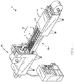
- Fig. 1 depicts an indexing motion packaging machine 2 that includes a web transport conveyor 4 transporting a web 6 of flexible packaging material from upstream to downstream through a series of stations including a forming station 10 that forms at least one product cavity 7 in the web 6, a loading station 12 that places food product P in the product cavity 7, and a closing station 14 that closes and/or seals the pocket with another web of flexible packaging material.
- a web transport conveyor 4 transporting a web 6 of flexible packaging material from upstream to downstream through a series of stations including a forming station 10 that forms at least one product cavity 7 in the web 6, a loading station 12 that places food product P in the product cavity 7, and a closing station 14 that closes and/or seals the pocket with another web of flexible packaging material.
- the forming station 10 includes a die box base 20 that is fixedly coupled to a frame assembly 30 (further described herein below) of the packaging machine 2.
- the die box base 20 includes a perimeteral surface 22 that corresponds to and abuts a perimeteral surface 42 on a forming die box 40 (further described herein below).
- the die box base 20 also defines at least one hole 24 (see Fig. 8 ) through which an engagement member 92 (further described herein below) extends.
- the forming station 10 includes the forming die box 40 which is configured to define at least one recess 44 in the web 6, into which the product cavity 7 is formed. A bottom surface of the recess 44 and/or the depth of the recess 44 is defined by an insert 60 (further described herein below) which is received in the recess 44.
- the forming die box 40 includes a shelf 46 (see Fig. 8 ) that radially projects into the recess 44 to axially support the insert 60 in the forming die box 40 (i.e. the shelf 46 prevents the insert 60 from falling through the recess 44 and out of the forming die box 40).
- the forming die box 40 also defines the perimeteral surface 42 that corresponds to and abuts the perimeteral surface 22 of the die box base 20.
- the number of recesses 44, the shape of the recess 44, the depths of the recesses 44, the recess depths, and/or other dimensions of the recess 44 can vary. In the example depicted in Fig. 2 , six rectangular recesses 44 are depicted.
- a handle 48 is coupled to the forming die box 40 to assist the user in moving the forming die box 40. Reference is made to US 7 607 279 A for further explanation of movable die boxes.
- the forming die box 40 is moveable into and out of the forming station 10 by a guide track assembly 70 that is configured to support the forming die box 40.
- the guide track assembly 70 allows the forming die box 40 to be moved between a staging position (see Fig. 2 ) such that the forming die box 40 can be easily removed (e.g. lifted) from the forming station 10 by an operator and a first position (see Figs. 3-4 ) in which the forming die box 40 is axially above the die box base 20.
- the guide track assembly 70 includes a pair of rails 72 having rollers 74 that reduce friction between the forming die box 40 and the guide track assembly 70 as the forming die box 40 is moved on the guide track assembly 70.
- the guide track assembly 70 is movable between a retracted position (see Fig. 3 ) in which the rails 72 are substantially vertical and adjacent to the frame assembly 30 and an extended position (see Fig. 2 ) such that the rail members 82 are substantially horizontal and support the forming die box 40 in a staging position (see Fig. 2 ) which is offset from the packaging machine 2.
- a retracted position see Fig. 3
- an extended position see Fig. 2
- an operator moves the guide track assembly 70 to the extended position (see Fig. 2 ) and places the forming die box 40 onto the rails 72.
- the operator then pushes the forming die box 40 along the rails 72 into the first position (see Fig. 3 ).
- the operator rotates the guide track assembly 70 back to the retracted position (see Figs. 3-4 ).
- the operator moves the guide track assembly 70 to the extended position and then pulls the forming die box 40 into the staging position (see Fig. 2 ).
- the operator can then remove the guide track assembly 70.
- a locking plate 38 secures the forming die box 40 to the die box base 20.
- the forming die box 40 is axially movable within the forming station 10 by a latching mechanism 80 that secures the forming die box 40 to the forming station 10 by moving the forming die box 40 into and out of engagement with the die box base 20.
- the latching mechanism 80 moves the forming die box 40 into and between the first position (see Figs. 3-4 ) in which the forming die box 40 is spaced apart from the die box base 20 and a second position (see Fig. 5 ) wherein the forming die box 40 is supported by the die box base 20 (or otherwise mates with or engages with the die box base 20).
- the latching mechanism 80 axially moves the forming die box 40 such that the perimeteral surface 22 of die box base 20 is supported by the perimeteral surface 42 of the forming die box 40.
- the forming die box 40 is freely laterally movable away from the die box base 20, and when the forming die box 40 is in the second position (see Fig. 5 ) the forming die box 40 is supported by the die box base 20.
- the forming die box 40 is supported by the die box base 20 in a manner that creates a fluid tight seal and define an interior vacuum space 28 (see Fig.
- a gasket 47 is included along the perimeteral surface 22 of the die box base 20 to create a vacuum tight seal between the forming die box 40 and the die box base 20.
- the latching mechanism 80 includes a rail member 82 for axially supporting the forming die box 40 in the first position (see Figs. 3-4 ).
- the rail member 82 includes a sloped surface 84 configured allow the forming die box 40 to slide along the rail member 82 when the forming die box 40 moves between the staging position (see Fig. 2 ) and the first position (see Figs. 3-4 ).
- the latching mechanism 80 includes an eccentric member 86 that is configured to rotate to thereby move the rail member 82 such that the forming die box 40 moves between the first position (see Figs. 3-4 ) and the second position (see Fig. 5 ).
- the eccentric member 86 moves the rail member 82 thereby moving the forming die box 40 into and between the first position (see Figs. 3-4 ) and the second position (see Fig. 5 ).
- the eccentric member 86 is rotatable in a first direction such that the rail member 82 axially moves downward and the forming die box 40 moves from the first position (see Figs. 3-4 ) to the second position (see Fig. 5 ); and the eccentric member 86 is rotatable in a second direction opposite the first direction such the rail member 82 axially moves upward and the forming die box 40 moves to the from the second position (see Fig. 5 ) to the first position (see Figs. 3-4 ).
- the shape of the eccentric member 86 can vary.
- the eccentric member 86 is a semicircle disk.
- the latching mechanism 80 includes a handle 88 by which an operator can manually rotate the eccentric member 86.
- the packaging machine 2 can form the product cavity 7 in the web 6.
- the forming die box 40 (which is in the second position) and the die box base 20 are supported by a movable base plate or frame assembly 30 which moves during operation of the packaging machine 2.
- the frame assembly 30 is movable between a lowered position axially below the web 6 such that the forming die box 40 is axially below the web 6 and the web 6 is allowed to advance; and a forming position such that the forming die box 40 engages the web 6 to thereby form the product cavity 7 in the web 6 (the forming die box 40 is depicted in dash-doubledot-dash line weight in Fig. 6 when the frame assembly 30 is in the forming position).
- the cover 26 which is stationary and fixedly mounted to the packaging machine 2 at the forming station 10) cooperates with forming die box 40 to create a vacuum in the interior vacuum space 28 and thereby form the product cavity 7 in the web 6.
- Vacuum equipment (not shown and known in the prior art) coupled to the die box base 20 creates the vacuum in the interior vacuum space 28 such that the product cavity 7 is formed in the web 6.
- the cover 26 optionally includes a plug assist mechanism having a plug member, a heat plate, and/or the like.
- the frame assembly 30 is moved between the lowered position and the forming position by lift arms 32 that are rotated by an actuator 35 (e.g. a servo motor) and belt 34 (see movement arrows A which depict movement of the lift arms 32 and the belt 34).
- the inserts 60 received in the forming die box 40 are shown in greater detail.
- the bottom surface of the recess 44 is defined by the insert 60 which is received or positioned in the recess 44 such that the insert 60 is axially movable in the recess 44 to thereby vary the depth of the recess 44 or the recess depth.
- the insert 60 includes a projection 62 that radially extends from the insert 60 to contact the shelf 46 of the forming die box 40 (see Fig. 8 ) such that the insert 60 is supported in the recess 44 (i.e. the projection 62 of the insert 60 contacts the shelf 46 to prevent the insert 60 from axially moving through the forming die box 40 in one axial direction).
- the insert 60 includes an upper end 63 and a lower end 64 opposite the lower end 64, and the projection 62 is located nearer the upper end 63 than the lower end 64 such that the lower end 64 is axially below the shelf 46 of the forming die box 40 when the shelf 46 contacts the projection 62 of the insert 60.
- the projection 62 has a curved surface 66 that defines a bottom perimeteral fillet of the recess 44.
- the insert 60 can change the shape of the recess 44 and/or the number of the recesses 44 defined in the forming die box 40 (i.e. an insert 60 can fill the entire recess 44 such that the number of product cavities 7 formed by the forming die box 40 is reduced (e.g.
- a forming die box 40 with six recesses 44 receives two inserts 60 that completely fill two recesses 44 such that the number of product cavities 7 formed by the forming die box 40 is reduced to four)).
- a variable depth mechanism 90 (described herein) is capable of moving the insert(s) 60 such that the number of product cavities 7 formed by the forming die box 40 is reduced.
- the forming station 10 includes the variable depth mechanism 90 that moves the insert 60 to thereby vary the depth of the recess 44.
- the variable depth mechanism 90 includes at least one engagement member 92 that is slideably received in the hole 24 of the die box base 20.
- the engagement member 92 comprises a first end 93 that extends into the interior vacuum space 28 defined by the forming die box 40 and the die box base 20 and a second end 94 opposite the first end 93.
- the engagement member 92 contacts the insert 60 to thereby move the insert 60 and vary the depth of the recess 44.
- the first end 93 of the engagement member 92 comprises a plate 96 configured to contact the insert 60 and/or multiple inserts 60 received in the recess(es) 44 of the forming die box 40.
- variable depth mechanism 90 can be adapted for use with any type (e.g. size, shape) of forming die box 40.
- the variable depth mechanism 90 includes a drive shaft 98 that is rotatably coupled to the die box base 20 and a platform member 100 that is coupled to the drive shaft 98 and the second end 94 of the engagement member 92.
- the platform member 100 includes screw threads and the drive shaft 98 includes screw threads that mate and/or engage with the screw threads of the platform member 100.
- An actuator 104 selectably rotates the drive shaft 98 such that the platform member 100 axially moves along the drive shaft 98 to axially move the insert 60 (e.g. when the drive shaft 98 is rotated by the actuator 104, the platform member 100 axially moves which causes the engagement member 92 to move).
- the actuator 104 is a servo motor which selectively moves a belt 105 to thereby rotate the drive shaft 98.
- the belt 105 moves in a first belt direction causing the drive shaft 98 to rotate in a counterclockwise direction; and when the drive shaft 98 actuates in a second servomotor direction, the belt 105 moves in a second belt direction causing the drive shaft 98 to rotate in a clockwise direction.
- the drive shaft 98 is rotatably supported by a fixed member assembly 108 that supports and allows rotation of the drive shaft 98. The fixed member assembly being fixed with respect to the die box base 20.
- the packaging machine 2 includes a controller 120 configured to control the components and devices of the packaging machine 2, including the components described herein.
- the controller 120 is configured to control movement of the web 6 via the web transport conveyor 4; actuation of the actuator 33 to move the lift arms 32 and the frame assembly 30, as described above; and/or the actuator 104 of the variable depth mechanism 90, as described above.
- the controller 120 is part of a system 118 included with the packaging machine 2.
- the system 118 includes a user input device 122 that allows the operator to input information into the system 118 to control the depth of the recess 44 in the forming die box 40.
- the operator can input into the user input device 122 a selected recess depth of 12,9 cm (3.0 inch) such that the controller 120 sends appropriate signals (via wired or wireless communication links 130) to the actuator 104 of the variable depth mechanism 90.
- the actuator 104 then axially moves the engagement member 92 to axially move the insert 60 within the recess 44 such that the insert 60 defines the depth of the recess 44 at the selected recess depth.
- the controller 120 includes a processing system 124, storage system 126, and software 128.
- the processing system 124 loads and executes software 128 from the storage system 126.
- the software 128 directs the processing system 124 to operate to carry out the methods described herein.
- the processing system 124 can comprise a microprocessor and other circuitry that retrieves and executes software 128 from storage system 126.
- Processing system 124 can be implemented within a single processing device but can also be distributed across multiple processing devices or sub-systems that cooperate in existing program instructions. Examples of processing system 124 include general purpose central processing units, applications specific processors, and logic devices, as well as any other type of processing device, combinations of processing devices, or variations thereof.
- the storage system 126 can comprise any storage media readable by processing system 124, and capable of storing software 128.
- the storage system 126 can include volatile and non-volatile, removable and non-removable media implemented in any method or technology for storage of information, such as computer readable instructions, data structures, program modules, or other data.
- Storage system 126 can be implemented as a single storage device but may also be implemented across multiple storage devices or sub-systems.
- Storage system 126 can further include additional elements, such as a controller, capable of communicating with the processing system 124.
- Examples of storage media include random access memory, read only memory, magnetic discs, optical discs, flash memory, virtual memory, and non-virtual memory, magnetic sets, magnetic tape, magnetic disc storage or other magnetic storage devices, or any other medium which can be used to storage the desired information and that may be accessed by an instruction execution system, as well as any combination or variation thereof, or any other type of storage medium.
- the storage media can be a non-transitory storage media.
- at least a portion of the storage media may be transitory. It should be understood that in no case is the storage media a propagated signal.
- User input device 122 can include a mouse, a keyboard, a voice input device, a touch input device, a motion input device, and other comparable input devices and associated processing elements capable of receiving user input from a user.
- Output devices such as a video display or graphical display can display an interface further associated with embodiments of the system and methods as disclosed herein. Speakers, printers, bells and other types of output devices may also be included in the user input device 122.
- the user input device 122 may display the system 118 on a display screen, and/or may announce it via a speaker.
- the forming station 10 includes a sleeve 101 that is coupled to the die box base 20 to support and seal the engagement member 92 with the die box base 20 as it slides in the hole 24 (see Figs. 7-8 ).
- the vacuum cups 102 are coupled to the die box base 20 and configured to create the vacuum in the interior vacuum space 28 (see Fig. 7 ).
- the packaging machine for forming a product cavity in a web includes a forming die box that defines a recess into which the product cavity is formed, an insert that is movable in the recess to thereby vary a depth of the recess, and a variable depth mechanism that moves the insert to vary the depth of the recess.
- the variable depth mechanism includes an engagement member that contacts the insert to thereby move the insert and vary the depth of the recess.
- a die box base supports the forming die box and defines an interior vacuum space therebetween, and the die box base further defines a hole that slidably receives the engagement member.
- the engagement member comprises a first end that extends into the interior vacuum space to thereby move the insert and vary the depth of the recess.
- the engagement member includes a second end opposite the first end.
- the variable depth mechanism can include a drive shaft, a platform member coupled to the drive shaft and the second end of the engagement member, and an actuator that selectively rotates the drive shaft such that the platform member moves along the drive shaft and the engagement member moves the insert.
- the variable depth mechanism includes a fixed member assembly that supports and allows rotation of the drive shaft.
- the fixed member assembly is fixed with respect to the die box base.
- the actuator is a servo motor.
- a computer controller controls the servo motor to thereby rotate the drive shaft.
- a latching mechanism that moves the forming die box into and between a first position in which the forming die box is spaced apart from the die box base and a second position in which the die box base supports the forming die box.
- the forming die box When in the first position, the forming die box is freely laterally movable away from the die box base, and when in the second position the forming die box is supported by the die box base.
- the forming die box has a perimeteral surface
- the die box base has a perimeteral surface that corresponds to and abuts the perimeteral surface of the forming die box in the second position.
- the latching mechanism has a rail member that supports the forming die box and an eccentric member such that rotation of the eccentric member moves the rail member thereby moving the forming die box into and between the first position and the second position.
- the latching mechanism has a handle configured to rotate the eccentric member.
- the forming die box includes a shelf that projects into the recess to support the insert in the forming die box, and the insert has a projection that radially extends from the insert and is supported by the shelf.
- the insert has an upper end and a lower end opposite the upper end such that the projection is positioned nearer the upper end than the lower end such that the lower end is axially below the shelf of the forming die box when the projection is supported by the shelf.
- the projection has a curved surface that defines a bottom fillet of the recess.
- the packaging machine for forming a product cavity in a web includes a forming die box that defines a recess into which the product cavity is formed, a die box base that supports the forming die box, and a latching mechanism that moves the forming die box into and between a first position in which the forming die box is spaced apart from the die box base and a second position in which the forming die box is supported by the die box base.
- the latching mechanism further comprises an eccentric member such that rotation of the eccentric member moves the forming die box into and between the first position and the second position.
- the latching mechanism includes a rail member for supporting the forming die box, wherein the rail member axially moves when the eccentric member rotates.
- a method for forming a product cavity in a web includes providing a forming die box that defines a recess into which the product cavity is formed, positioning an insert in the forming die box such that the insert is axially movable in the recess to thereby vary a depth of the recess, actuating a variable depth mechanism to move the insert to vary the depth of the recess, and forming the product cavity in the web.
- the method can include rotating a drive shaft that moves a platform member of the variable depth mechanism such that the engagement member moves.
- the apparatus and method according to the invention allows a simplified, user-friendly, and automated recess depth change for forming die boxes.
Claims (13)
- Verpackungsmaschine zum Ausbilden eines Produkthohlraums (7) in einer Bahn (6), wobei die Verpackungsmaschine (2) Folgendes umfasst:einen Formungswerkzeugkasten (40), der eine Ausnehmung (44) festlegt, in die der Produkthohlraum (7) eingeformt ist,eine Werkzeugkastenbasis (20),einen Einsatz (60), der in der Ausnehmung (44) axial bewegbar ist, umdadurch eine Tiefe der Ausnehmung (44) zu verändern, undeinen veränderlichen Tiefenmechanismus (90), der den Einsatz (60) selektiv bewegt, um die Tiefe der Ausnehmung (44) zu verändern,dadurch gekennzeichnet, dassdie Verpackungsmaschine (2) einen Verriegelungsmechanismus (80) umfasst, über den der Formungswerkzeugkasten (40) in eine erste Stellung, in der der Formungswerkzeugkasten (40) von der Werkzeugkastenbasis (20) beabstandet ist, und eine zweite Stellung, in der der Formungswerkzeugkasten (40) von der Werkzeugkastenbasis (20) getragen ist, und zwischen diesen Stellungen bewegbar ist, undder Formungswerkzeugkasten (40) in der ersten Stellung frei von der Werkzeugkastenbasis (20) seitlich weg bewegbar ist.
- Verpackungsmaschine nach Anspruch 1, dadurch gekennzeichnet, dass der veränderliche Tiefenmechanismus (90) ein Eingriffselement (92) umfasst, das den Einsatz (60) berührt, um dadurch den Einsatz (60) zu bewegen und die Tiefe der Ausnehmung (44) zu verändern.
- Verpackungsmaschine nach Anspruch 2, dadurch gekennzeichnet, dass die Werkzeugkastenbasis (20) einen inneren Vakuumraum (28) zwischen sich und dem Formungswerkzeugkasten (40) festlegt, wobei die Werkzeugkastenbasis (20) ferner ein Loch (24) festlegt, durch das sich das Eingriffselement (92) erstreckt, und wobei das Eingriffselement (92) ein erstes Ende (93) umfasst, das in dem inneren Vakuumraum (28) angeordnet und dazu ausgelegt ist, den Einsatz (60) zu bewegen, um die Tiefe der Ausnehmung (44) zu verändern.
- Verpackungsmaschine nach Anspruch 3, dadurch gekennzeichnet, dass das Eingriffselement (92) ferner ein zweites Ende (94) umfasst, das dem ersten Ende (93) gegenüberliegt, und der veränderliche Tiefenmechanismus (90) ferner Folgendes umfasst:eine Antriebswelle (98),ein Plattformelement (100), das mit der Antriebswelle (98) und dem zweiten Ende (94) des Eingriffselements (92) gekoppelt ist, undeinen Stellantrieb (104), der die Antriebswelle (98) auf eine solche Weise selektiv dreht, dass sich das Plattformelement (100) entlang der Antriebswelle (98) bewegt und das Eingriffselement (92) den Einsatz (60) bewegt.
- Verpackungsmaschine nach Anspruch 4, dadurch gekennzeichnet, dass der veränderliche Tiefenmechanismus (90) ferner eine feste Elementanordnung (108) umfasst, die die Antriebswelle (98) trägt und eine Drehung derselben ermöglicht, wobei die feste Elementanordnung (108) in Bezug auf die Werkzeugkastenbasis (20) fest ist.
- Verpackungsmaschine nach Anspruch 4 oder 5, dadurch gekennzeichnet, dass der Stellantrieb (108) ein Servomotor ist und der veränderliche Tiefenmechanismus (90) ferner eine Computersteuerung (120) umfasst, die den Servomotor steuert, um dadurch die Antriebwelle (98) zu drehen.
- Verpackungsmaschine nach einem der vorhergehenden Ansprüche, dadurch gekennzeichnet, dass der Formungswerkzeugkasten (40) eine Umfangsfläche (42) umfasst und die Werkzeugkastenbasis (20) eine Umfangsfläche (22) umfasst, die der Umfangsfläche (42) des Formungswerkzeugkastens (40) in der zweiten Stellung entspricht und an dieser anliegt.
- Verpackungsmaschine nach einem der vorhergehenden Ansprüche, dadurch gekennzeichnet, dass der Verriegelungsmechanismus (80) ein Schienenelement (82) umfasst, das den Formungswerkzeugkasten (40) und ein exzentrisches Element (86) trägt, wobei eine Drehung des exzentrischen Elements (86) das Schienenelement (82) bewegt und dadurch den Formungswerkzeugkasten (40) in die erste Stellung und die zweite Stellung und zwischen diesen Stellungen bewegt.
- Verpackungsmaschine nach Anspruch 8, dadurch gekennzeichnet, dass der Verriegelungsmechanismus (80) ferner einen Griff (88) umfasst, der dazu ausgelegt ist, das exzentrische Element (86) zu drehen.
- Verpackungsmaschine nach einem der vorhergehenden Ansprüche, dadurch gekennzeichnet, dass der Formungswerkzeugkasten (40) eine Ablageplatte (46) umfasst, die in die Ausnehmung (44) vorsteht und den Einsatz (60) in dem Formungswerkzeugkasten (40) trägt.
- Verpackungsmaschine nach Anspruch 10, dadurch gekennzeichnet, dass der Einsatz (60) einen Vorsprung (62) umfasst, der sich radial von dem Einsatz (60) erstreckt und von der Ablageplatte (46) getragen ist.
- Verpackungsmaschine nach Anspruch 11, dadurch gekennzeichnet, dass der Einsatz (60) ferner ein oberes Ende (63) und ein dem oberen Ende (63) des Einsatzes (60) gegenüberliegendes unteres Ende (64) umfasst und der Vorsprung (62) auf eine solche Weise näher an dem oberen Ende (63) des Einsatzes (60) als an dem unteren Ende (64) des Einsatzes (60) positioniert ist, dass sich das untere Ende (64) des Einsatzes (60) axial unter der Ablageplatte (46) des Formungswerkzeugkastens (40) befindet, wenn der Vorsprung (62) von der Ablageplatte (46) getragen ist.
- Verpackungsmaschine nach Anspruch 11 oder 12, dadurch gekennzeichnet, dass der Vorsprung (62) eine gekrümmte Fläche (66) aufweist, die dazu ausgelegt ist, eine Bodenkehle der Ausnehmung (44) festzulegen.
Applications Claiming Priority (2)
| Application Number | Priority Date | Filing Date | Title |
|---|---|---|---|
| US201562241359P | 2015-10-14 | 2015-10-14 | |
| US15/289,604 US10625892B2 (en) | 2015-10-14 | 2016-10-10 | Web packaging machines with variable depth forming |
Publications (3)
| Publication Number | Publication Date |
|---|---|
| EP3156339A2 EP3156339A2 (de) | 2017-04-19 |
| EP3156339A3 EP3156339A3 (de) | 2017-06-28 |
| EP3156339B1 true EP3156339B1 (de) | 2019-05-29 |
Family
ID=57209146
Family Applications (1)
| Application Number | Title | Priority Date | Filing Date |
|---|---|---|---|
| EP16020400.4A Revoked EP3156339B1 (de) | 2015-10-14 | 2016-10-13 | Bahnverpackungsmaschine mit variabler tiefenerzeugung |
Country Status (2)
| Country | Link |
|---|---|
| US (3) | US10625892B2 (de) |
| EP (1) | EP3156339B1 (de) |
Families Citing this family (4)
| Publication number | Priority date | Publication date | Assignee | Title |
|---|---|---|---|---|
| US10625892B2 (en) * | 2015-10-14 | 2020-04-21 | Alkar-Rapidpak, Inc. | Web packaging machines with variable depth forming |
| DE102017121438A1 (de) * | 2017-09-15 | 2019-03-21 | Multivac Sepp Haggenmüller Se & Co. Kg | Tiefziehverpackungsmaschine und Verfahren zum Formen einer Folienbahn in Kartonelemente |
| PL3724083T3 (pl) * | 2017-12-14 | 2022-10-17 | Stampac Gmbh | System narzędzi dla urządzenia do pakowania oraz jednostka formująca do formowania kształtek foliowych |
| FR3093093B1 (fr) * | 2019-02-25 | 2021-03-05 | Acemma | Dispositif de dosage motorise a bande, systeme d’ensachage associe |
Citations (14)
| Publication number | Priority date | Publication date | Assignee | Title |
|---|---|---|---|---|
| US196117A (en) | 1877-10-16 | Improvement in hoisting-jacks | ||
| DE1120119B (de) | 1955-11-03 | 1961-12-21 | Max Braun Fa | Verfahren und Vorrichtung zum Herstellen eines offenen Hohlkoerpers nach Art einer Schale aus einer Folie oder Platte aus organischem thermoplastischem Kunststoff nach der Methode des Vakuum-Tiefziehens |
| US3218776A (en) | 1961-09-11 | 1965-11-23 | Cloud Machine Corp | Packaging method and apparatus |
| US3546746A (en) | 1966-12-13 | 1970-12-15 | Shell Oil Co | Apparatus for forming hollow articles of work-strengthenable plastic materials |
| US3869052A (en) | 1973-09-14 | 1975-03-04 | Beatrice Foods Co | Truck for loading oven compartments |
| US5323590A (en) | 1986-09-03 | 1994-06-28 | Seawell North America, Inc. | Method of producing food packaging with gas between tensioned film and lid |
| US7168549B1 (en) | 2005-01-11 | 2007-01-30 | Honda Motor Co., Ltd. | Programmable modular pneumatic lift |
| US7490448B1 (en) | 2007-03-09 | 2009-02-17 | Alkar-Rapidpak, Inc. | Form-fill-seal web packaging system with sealing station |
| US7607279B2 (en) | 2006-03-31 | 2009-10-27 | Alkar-Rapidpak, Inc. | Web packaging system with ergonomic tooling change |
| WO2011104036A2 (de) | 2010-02-26 | 2011-09-01 | Cfs Germany Gmbh | Verfahren zum wechsel des ober- und unterwerkzeugs einer verpackungsmaschine |
| US8181432B2 (en) | 2007-10-23 | 2012-05-22 | Alkar-Rapidpak-Mp Equipment, Inc. | Web packaging system with ergonomic forming plug change |
| US8539743B2 (en) | 2007-04-24 | 2013-09-24 | Aroma Systems, SRL | Machine for packaging in capsules, also in vacuum and/or controlled atmosphere |
| EP2769923A1 (de) | 2013-02-22 | 2014-08-27 | Multivac Sepp Haggenmüller GmbH & Co. KG | Tiefziehverpackungsmaschine mit Siegelstation und Verfahren |
| EP2985234A1 (de) | 2014-08-13 | 2016-02-17 | Multivac Sepp Haggenmüller GmbH & Co. KG | Tiefziehverpackungsmaschine mit bewegbarem Formeinsatz |
Family Cites Families (8)
| Publication number | Priority date | Publication date | Assignee | Title |
|---|---|---|---|---|
| DE9010832U1 (de) * | 1990-07-20 | 1990-09-27 | Laecovac-Vakuumtechnik Gmbh, 4516 Bissendorf, De | |
| US6659417B2 (en) * | 2002-03-12 | 2003-12-09 | Wu-Hong Hsieh | Elevating device for adjusting a telescopic tube used to support a musical instrument |
| DE102009020892A1 (de) * | 2009-05-13 | 2011-02-10 | Multivac Sepp Haggenmüller Gmbh & Co. Kg | Verpackungsmaschine und Verfahren zum Verschließen von Behältern mit Deckeln |
| US8499536B2 (en) * | 2009-05-18 | 2013-08-06 | Alkar-Rapidpak-Mp Equipment, Inc. | Apparatuses and methods for assisted tooling extraction |
| DE102011105513A1 (de) * | 2011-06-24 | 2012-12-27 | Multivac Sepp Haggenmüller Gmbh & Co. Kg | Verfahren und Siegelstation zum Versiegeln von Verpackungen |
| DE102012111497A1 (de) * | 2012-11-27 | 2014-05-28 | Gea Food Solutions Germany Gmbh | Verpackungsmaschine mit einer Komplettierungsanzeige |
| ES2579339T3 (es) * | 2013-09-20 | 2016-08-10 | Multivac Sepp Haggenmüller Gmbh & Co. Kg | Máquina de cierre de bandejas con cuerpo de cinta intercambiable |
| US10625892B2 (en) * | 2015-10-14 | 2020-04-21 | Alkar-Rapidpak, Inc. | Web packaging machines with variable depth forming |
-
2016
- 2016-10-10 US US15/289,604 patent/US10625892B2/en active Active
- 2016-10-13 EP EP16020400.4A patent/EP3156339B1/de not_active Revoked
-
2020
- 2020-03-16 US US16/819,897 patent/US11305905B2/en active Active
-
2022
- 2022-03-28 US US17/705,533 patent/US20220212825A1/en active Pending
Patent Citations (15)
| Publication number | Priority date | Publication date | Assignee | Title |
|---|---|---|---|---|
| US196117A (en) | 1877-10-16 | Improvement in hoisting-jacks | ||
| DE1120119B (de) | 1955-11-03 | 1961-12-21 | Max Braun Fa | Verfahren und Vorrichtung zum Herstellen eines offenen Hohlkoerpers nach Art einer Schale aus einer Folie oder Platte aus organischem thermoplastischem Kunststoff nach der Methode des Vakuum-Tiefziehens |
| US3218776A (en) | 1961-09-11 | 1965-11-23 | Cloud Machine Corp | Packaging method and apparatus |
| US3546746A (en) | 1966-12-13 | 1970-12-15 | Shell Oil Co | Apparatus for forming hollow articles of work-strengthenable plastic materials |
| US3869052A (en) | 1973-09-14 | 1975-03-04 | Beatrice Foods Co | Truck for loading oven compartments |
| US5323590A (en) | 1986-09-03 | 1994-06-28 | Seawell North America, Inc. | Method of producing food packaging with gas between tensioned film and lid |
| US7168549B1 (en) | 2005-01-11 | 2007-01-30 | Honda Motor Co., Ltd. | Programmable modular pneumatic lift |
| US7607279B2 (en) | 2006-03-31 | 2009-10-27 | Alkar-Rapidpak, Inc. | Web packaging system with ergonomic tooling change |
| US7490448B1 (en) | 2007-03-09 | 2009-02-17 | Alkar-Rapidpak, Inc. | Form-fill-seal web packaging system with sealing station |
| US8539743B2 (en) | 2007-04-24 | 2013-09-24 | Aroma Systems, SRL | Machine for packaging in capsules, also in vacuum and/or controlled atmosphere |
| US8181432B2 (en) | 2007-10-23 | 2012-05-22 | Alkar-Rapidpak-Mp Equipment, Inc. | Web packaging system with ergonomic forming plug change |
| WO2011104036A2 (de) | 2010-02-26 | 2011-09-01 | Cfs Germany Gmbh | Verfahren zum wechsel des ober- und unterwerkzeugs einer verpackungsmaschine |
| EP2769923A1 (de) | 2013-02-22 | 2014-08-27 | Multivac Sepp Haggenmüller GmbH & Co. KG | Tiefziehverpackungsmaschine mit Siegelstation und Verfahren |
| EP2985234A1 (de) | 2014-08-13 | 2016-02-17 | Multivac Sepp Haggenmüller GmbH & Co. KG | Tiefziehverpackungsmaschine mit bewegbarem Formeinsatz |
| US20160046063A1 (en) | 2014-08-13 | 2016-02-18 | Multivac Sepp Haggenmüller Gmbh & Co. Kg | Thermoform packaging machine with movable mold |
Also Published As
| Publication number | Publication date |
|---|---|
| US10625892B2 (en) | 2020-04-21 |
| US20220212825A1 (en) | 2022-07-07 |
| EP3156339A2 (de) | 2017-04-19 |
| EP3156339A3 (de) | 2017-06-28 |
| US20200216209A1 (en) | 2020-07-09 |
| US11305905B2 (en) | 2022-04-19 |
| US20170107006A1 (en) | 2017-04-20 |
Similar Documents
| Publication | Publication Date | Title |
|---|---|---|
| US20200216209A1 (en) | Web packaging machines with variable depth forming | |
| JP6193346B2 (ja) | 深絞り紙トレイ、深絞り紙トレイを製造する方法および装置、ならびにトレイ状製品包装容器 | |
| CN206882501U (zh) | 补强钢片裁切载带包装机 | |
| CN204525630U (zh) | 载带成型设备 | |
| KR100842870B1 (ko) | 구이 김 절단 및 수납장치 | |
| JP5161961B2 (ja) | 工作機械用の改良型往復運動装置 | |
| JP5941519B2 (ja) | 食品生地の成形方法及び装置 | |
| KR20190088965A (ko) | 절단 장치 및 블리스터 포장기 | |
| WO2012090304A1 (ja) | プレス成形システム | |
| CN104191341A (zh) | 新型抛光机 | |
| CN106346355B (zh) | 管件自动进出料机构 | |
| CN105690455A (zh) | 一种用于纸板裁剪的装置 | |
| EP2383091B1 (de) | Werkzeugwechselsystem für eine Verpackungsmaschine | |
| CN105266182A (zh) | 食品成形装置及食品成形装置用卷帘 | |
| JP5736010B2 (ja) | 板材の切断装置 | |
| JP2013141679A (ja) | ブランキング加工方法および装置 | |
| JP2011131226A (ja) | パンチプレス | |
| JP2019038016A (ja) | 成形型の交換方法 | |
| EP2902180A1 (de) | Stempelvorrichtung vom flash-stempel-typ für seifenstücke zur herstellung von kosmetikseifen, wäscheseifen oder dergleichen | |
| JP2012179672A (ja) | 野菜類の芯取り切断装置 | |
| US10875670B2 (en) | Web-packaging machines with multiple sealing stations | |
| US2951425A (en) | Deburring machine | |
| CN110239783B (zh) | 工作交替连续式气调包装机 | |
| KR20170077398A (ko) | 다단 가공을 위한 회전형 트랜스퍼를 구비한 프레스 | |
| JP2013146776A (ja) | 順送り式プレス加工用ダイユニット、順送り式プレス加工装置およびその装置を用いた三次元精密部品の製造方法 |
Legal Events
| Date | Code | Title | Description |
|---|---|---|---|
| PUAI | Public reference made under article 153(3) epc to a published international application that has entered the european phase |
Free format text: ORIGINAL CODE: 0009012 |
|
| STAA | Information on the status of an ep patent application or granted ep patent |
Free format text: STATUS: THE APPLICATION HAS BEEN PUBLISHED |
|
| AK | Designated contracting states |
Kind code of ref document: A2 Designated state(s): AL AT BE BG CH CY CZ DE DK EE ES FI FR GB GR HR HU IE IS IT LI LT LU LV MC MK MT NL NO PL PT RO RS SE SI SK SM TR |
|
| AX | Request for extension of the european patent |
Extension state: BA ME |
|
| PUAL | Search report despatched |
Free format text: ORIGINAL CODE: 0009013 |
|
| AK | Designated contracting states |
Kind code of ref document: A3 Designated state(s): AL AT BE BG CH CY CZ DE DK EE ES FI FR GB GR HR HU IE IS IT LI LT LU LV MC MK MT NL NO PL PT RO RS SE SI SK SM TR |
|
| AX | Request for extension of the european patent |
Extension state: BA ME |
|
| RIC1 | Information provided on ipc code assigned before grant |
Ipc: B65B 59/00 20060101ALI20170522BHEP Ipc: B65B 59/04 20060101ALI20170522BHEP Ipc: B65B 9/04 20060101AFI20170522BHEP Ipc: B65B 47/10 20060101ALI20170522BHEP |
|
| STAA | Information on the status of an ep patent application or granted ep patent |
Free format text: STATUS: REQUEST FOR EXAMINATION WAS MADE |
|
| 17P | Request for examination filed |
Effective date: 20171207 |
|
| RBV | Designated contracting states (corrected) |
Designated state(s): AL AT BE BG CH CY CZ DE DK EE ES FI FR GB GR HR HU IE IS IT LI LT LU LV MC MK MT NL NO PL PT RO RS SE SI SK SM TR |
|
| STAA | Information on the status of an ep patent application or granted ep patent |
Free format text: STATUS: EXAMINATION IS IN PROGRESS |
|
| 17Q | First examination report despatched |
Effective date: 20180208 |
|
| GRAP | Despatch of communication of intention to grant a patent |
Free format text: ORIGINAL CODE: EPIDOSNIGR1 |
|
| STAA | Information on the status of an ep patent application or granted ep patent |
Free format text: STATUS: GRANT OF PATENT IS INTENDED |
|
| INTG | Intention to grant announced |
Effective date: 20181203 |
|
| GRAJ | Information related to disapproval of communication of intention to grant by the applicant or resumption of examination proceedings by the epo deleted |
Free format text: ORIGINAL CODE: EPIDOSDIGR1 |
|
| STAA | Information on the status of an ep patent application or granted ep patent |
Free format text: STATUS: EXAMINATION IS IN PROGRESS |
|
| GRAP | Despatch of communication of intention to grant a patent |
Free format text: ORIGINAL CODE: EPIDOSNIGR1 |
|
| INTC | Intention to grant announced (deleted) | ||
| STAA | Information on the status of an ep patent application or granted ep patent |
Free format text: STATUS: GRANT OF PATENT IS INTENDED |
|
| GRAS | Grant fee paid |
Free format text: ORIGINAL CODE: EPIDOSNIGR3 |
|
| GRAA | (expected) grant |
Free format text: ORIGINAL CODE: 0009210 |
|
| STAA | Information on the status of an ep patent application or granted ep patent |
Free format text: STATUS: THE PATENT HAS BEEN GRANTED |
|
| INTG | Intention to grant announced |
Effective date: 20190411 |
|
| AK | Designated contracting states |
Kind code of ref document: B1 Designated state(s): AL AT BE BG CH CY CZ DE DK EE ES FI FR GB GR HR HU IE IS IT LI LT LU LV MC MK MT NL NO PL PT RO RS SE SI SK SM TR |
|
| REG | Reference to a national code |
Ref country code: GB Ref legal event code: FG4D |
|
| REG | Reference to a national code |
Ref country code: CH Ref legal event code: EP |
|
| REG | Reference to a national code |
Ref country code: AT Ref legal event code: REF Ref document number: 1138116 Country of ref document: AT Kind code of ref document: T Effective date: 20190615 |
|
| REG | Reference to a national code |
Ref country code: DE Ref legal event code: R096 Ref document number: 602016014488 Country of ref document: DE |
|
| REG | Reference to a national code |
Ref country code: IE Ref legal event code: FG4D |
|
| REG | Reference to a national code |
Ref country code: NL Ref legal event code: MP Effective date: 20190529 |
|
| REG | Reference to a national code |
Ref country code: LT Ref legal event code: MG4D |
|
| PG25 | Lapsed in a contracting state [announced via postgrant information from national office to epo] |
Ref country code: AL Free format text: LAPSE BECAUSE OF FAILURE TO SUBMIT A TRANSLATION OF THE DESCRIPTION OR TO PAY THE FEE WITHIN THE PRESCRIBED TIME-LIMIT Effective date: 20190529 Ref country code: FI Free format text: LAPSE BECAUSE OF FAILURE TO SUBMIT A TRANSLATION OF THE DESCRIPTION OR TO PAY THE FEE WITHIN THE PRESCRIBED TIME-LIMIT Effective date: 20190529 Ref country code: HR Free format text: LAPSE BECAUSE OF FAILURE TO SUBMIT A TRANSLATION OF THE DESCRIPTION OR TO PAY THE FEE WITHIN THE PRESCRIBED TIME-LIMIT Effective date: 20190529 Ref country code: LT Free format text: LAPSE BECAUSE OF FAILURE TO SUBMIT A TRANSLATION OF THE DESCRIPTION OR TO PAY THE FEE WITHIN THE PRESCRIBED TIME-LIMIT Effective date: 20190529 Ref country code: SE Free format text: LAPSE BECAUSE OF FAILURE TO SUBMIT A TRANSLATION OF THE DESCRIPTION OR TO PAY THE FEE WITHIN THE PRESCRIBED TIME-LIMIT Effective date: 20190529 Ref country code: ES Free format text: LAPSE BECAUSE OF FAILURE TO SUBMIT A TRANSLATION OF THE DESCRIPTION OR TO PAY THE FEE WITHIN THE PRESCRIBED TIME-LIMIT Effective date: 20190529 Ref country code: NO Free format text: LAPSE BECAUSE OF FAILURE TO SUBMIT A TRANSLATION OF THE DESCRIPTION OR TO PAY THE FEE WITHIN THE PRESCRIBED TIME-LIMIT Effective date: 20190829 Ref country code: PT Free format text: LAPSE BECAUSE OF FAILURE TO SUBMIT A TRANSLATION OF THE DESCRIPTION OR TO PAY THE FEE WITHIN THE PRESCRIBED TIME-LIMIT Effective date: 20190930 |
|
| PG25 | Lapsed in a contracting state [announced via postgrant information from national office to epo] |
Ref country code: LV Free format text: LAPSE BECAUSE OF FAILURE TO SUBMIT A TRANSLATION OF THE DESCRIPTION OR TO PAY THE FEE WITHIN THE PRESCRIBED TIME-LIMIT Effective date: 20190529 Ref country code: GR Free format text: LAPSE BECAUSE OF FAILURE TO SUBMIT A TRANSLATION OF THE DESCRIPTION OR TO PAY THE FEE WITHIN THE PRESCRIBED TIME-LIMIT Effective date: 20190830 Ref country code: BG Free format text: LAPSE BECAUSE OF FAILURE TO SUBMIT A TRANSLATION OF THE DESCRIPTION OR TO PAY THE FEE WITHIN THE PRESCRIBED TIME-LIMIT Effective date: 20190829 Ref country code: RS Free format text: LAPSE BECAUSE OF FAILURE TO SUBMIT A TRANSLATION OF THE DESCRIPTION OR TO PAY THE FEE WITHIN THE PRESCRIBED TIME-LIMIT Effective date: 20190529 |
|
| REG | Reference to a national code |
Ref country code: AT Ref legal event code: MK05 Ref document number: 1138116 Country of ref document: AT Kind code of ref document: T Effective date: 20190529 |
|
| PG25 | Lapsed in a contracting state [announced via postgrant information from national office to epo] |
Ref country code: CZ Free format text: LAPSE BECAUSE OF FAILURE TO SUBMIT A TRANSLATION OF THE DESCRIPTION OR TO PAY THE FEE WITHIN THE PRESCRIBED TIME-LIMIT Effective date: 20190529 Ref country code: RO Free format text: LAPSE BECAUSE OF FAILURE TO SUBMIT A TRANSLATION OF THE DESCRIPTION OR TO PAY THE FEE WITHIN THE PRESCRIBED TIME-LIMIT Effective date: 20190529 Ref country code: AT Free format text: LAPSE BECAUSE OF FAILURE TO SUBMIT A TRANSLATION OF THE DESCRIPTION OR TO PAY THE FEE WITHIN THE PRESCRIBED TIME-LIMIT Effective date: 20190529 Ref country code: NL Free format text: LAPSE BECAUSE OF FAILURE TO SUBMIT A TRANSLATION OF THE DESCRIPTION OR TO PAY THE FEE WITHIN THE PRESCRIBED TIME-LIMIT Effective date: 20190529 Ref country code: EE Free format text: LAPSE BECAUSE OF FAILURE TO SUBMIT A TRANSLATION OF THE DESCRIPTION OR TO PAY THE FEE WITHIN THE PRESCRIBED TIME-LIMIT Effective date: 20190529 Ref country code: DK Free format text: LAPSE BECAUSE OF FAILURE TO SUBMIT A TRANSLATION OF THE DESCRIPTION OR TO PAY THE FEE WITHIN THE PRESCRIBED TIME-LIMIT Effective date: 20190529 Ref country code: SK Free format text: LAPSE BECAUSE OF FAILURE TO SUBMIT A TRANSLATION OF THE DESCRIPTION OR TO PAY THE FEE WITHIN THE PRESCRIBED TIME-LIMIT Effective date: 20190529 |
|
| REG | Reference to a national code |
Ref country code: DE Ref legal event code: R026 Ref document number: 602016014488 Country of ref document: DE |
|
| PLBI | Opposition filed |
Free format text: ORIGINAL CODE: 0009260 |
|
| PLBI | Opposition filed |
Free format text: ORIGINAL CODE: 0009260 |
|
| PG25 | Lapsed in a contracting state [announced via postgrant information from national office to epo] |
Ref country code: SM Free format text: LAPSE BECAUSE OF FAILURE TO SUBMIT A TRANSLATION OF THE DESCRIPTION OR TO PAY THE FEE WITHIN THE PRESCRIBED TIME-LIMIT Effective date: 20190529 Ref country code: IT Free format text: LAPSE BECAUSE OF FAILURE TO SUBMIT A TRANSLATION OF THE DESCRIPTION OR TO PAY THE FEE WITHIN THE PRESCRIBED TIME-LIMIT Effective date: 20190529 |
|
| PLAX | Notice of opposition and request to file observation + time limit sent |
Free format text: ORIGINAL CODE: EPIDOSNOBS2 |
|
| 26 | Opposition filed |
Opponent name: GEA FOOD SOLUTIONS GERMANY GMBH Effective date: 20200210 |
|
| 26 | Opposition filed |
Opponent name: MULTIVAC SEPP HAGGENMUELLER SE & CO. KG Effective date: 20200213 |
|
| PG25 | Lapsed in a contracting state [announced via postgrant information from national office to epo] |
Ref country code: TR Free format text: LAPSE BECAUSE OF FAILURE TO SUBMIT A TRANSLATION OF THE DESCRIPTION OR TO PAY THE FEE WITHIN THE PRESCRIBED TIME-LIMIT Effective date: 20190529 |
|
| PG25 | Lapsed in a contracting state [announced via postgrant information from national office to epo] |
Ref country code: PL Free format text: LAPSE BECAUSE OF FAILURE TO SUBMIT A TRANSLATION OF THE DESCRIPTION OR TO PAY THE FEE WITHIN THE PRESCRIBED TIME-LIMIT Effective date: 20190529 |
|
| PG25 | Lapsed in a contracting state [announced via postgrant information from national office to epo] |
Ref country code: SI Free format text: LAPSE BECAUSE OF FAILURE TO SUBMIT A TRANSLATION OF THE DESCRIPTION OR TO PAY THE FEE WITHIN THE PRESCRIBED TIME-LIMIT Effective date: 20190529 Ref country code: MC Free format text: LAPSE BECAUSE OF FAILURE TO SUBMIT A TRANSLATION OF THE DESCRIPTION OR TO PAY THE FEE WITHIN THE PRESCRIBED TIME-LIMIT Effective date: 20190529 |
|
| REG | Reference to a national code |
Ref country code: CH Ref legal event code: PL |
|
| PLBB | Reply of patent proprietor to notice(s) of opposition received |
Free format text: ORIGINAL CODE: EPIDOSNOBS3 |
|
| PG25 | Lapsed in a contracting state [announced via postgrant information from national office to epo] |
Ref country code: LI Free format text: LAPSE BECAUSE OF NON-PAYMENT OF DUE FEES Effective date: 20191031 Ref country code: CH Free format text: LAPSE BECAUSE OF NON-PAYMENT OF DUE FEES Effective date: 20191031 Ref country code: LU Free format text: LAPSE BECAUSE OF NON-PAYMENT OF DUE FEES Effective date: 20191013 |
|
| REG | Reference to a national code |
Ref country code: BE Ref legal event code: MM Effective date: 20191031 |
|
| PG25 | Lapsed in a contracting state [announced via postgrant information from national office to epo] |
Ref country code: BE Free format text: LAPSE BECAUSE OF NON-PAYMENT OF DUE FEES Effective date: 20191031 |
|
| PG25 | Lapsed in a contracting state [announced via postgrant information from national office to epo] |
Ref country code: FR Free format text: LAPSE BECAUSE OF NON-PAYMENT OF DUE FEES Effective date: 20191031 Ref country code: IE Free format text: LAPSE BECAUSE OF NON-PAYMENT OF DUE FEES Effective date: 20191013 |
|
| PGFP | Annual fee paid to national office [announced via postgrant information from national office to epo] |
Ref country code: GB Payment date: 20200930 Year of fee payment: 5 |
|
| PG25 | Lapsed in a contracting state [announced via postgrant information from national office to epo] |
Ref country code: CY Free format text: LAPSE BECAUSE OF FAILURE TO SUBMIT A TRANSLATION OF THE DESCRIPTION OR TO PAY THE FEE WITHIN THE PRESCRIBED TIME-LIMIT Effective date: 20190529 |
|
| PG25 | Lapsed in a contracting state [announced via postgrant information from national office to epo] |
Ref country code: IS Free format text: LAPSE BECAUSE OF FAILURE TO SUBMIT A TRANSLATION OF THE DESCRIPTION OR TO PAY THE FEE WITHIN THE PRESCRIBED TIME-LIMIT Effective date: 20190929 |
|
| PG25 | Lapsed in a contracting state [announced via postgrant information from national office to epo] |
Ref country code: HU Free format text: LAPSE BECAUSE OF FAILURE TO SUBMIT A TRANSLATION OF THE DESCRIPTION OR TO PAY THE FEE WITHIN THE PRESCRIBED TIME-LIMIT; INVALID AB INITIO Effective date: 20161013 Ref country code: MT Free format text: LAPSE BECAUSE OF FAILURE TO SUBMIT A TRANSLATION OF THE DESCRIPTION OR TO PAY THE FEE WITHIN THE PRESCRIBED TIME-LIMIT Effective date: 20190529 |
|
| REG | Reference to a national code |
Ref country code: DE Ref legal event code: R103 Ref document number: 602016014488 Country of ref document: DE Ref country code: DE Ref legal event code: R064 Ref document number: 602016014488 Country of ref document: DE |
|
| GBPC | Gb: european patent ceased through non-payment of renewal fee |
Effective date: 20211013 |
|
| PG25 | Lapsed in a contracting state [announced via postgrant information from national office to epo] |
Ref country code: MK Free format text: LAPSE BECAUSE OF FAILURE TO SUBMIT A TRANSLATION OF THE DESCRIPTION OR TO PAY THE FEE WITHIN THE PRESCRIBED TIME-LIMIT Effective date: 20190529 |
|
| PG25 | Lapsed in a contracting state [announced via postgrant information from national office to epo] |
Ref country code: GB Free format text: LAPSE BECAUSE OF NON-PAYMENT OF DUE FEES Effective date: 20211013 |
|
| RDAF | Communication despatched that patent is revoked |
Free format text: ORIGINAL CODE: EPIDOSNREV1 |
|
| RDAG | Patent revoked |
Free format text: ORIGINAL CODE: 0009271 |
|
| STAA | Information on the status of an ep patent application or granted ep patent |
Free format text: STATUS: PATENT REVOKED |
|
| PGFP | Annual fee paid to national office [announced via postgrant information from national office to epo] |
Ref country code: DE Payment date: 20220914 Year of fee payment: 7 |
|
| REG | Reference to a national code |
Ref country code: CH Ref legal event code: PL |
|
| RAP2 | Party data changed (patent owner data changed or rights of a patent transferred) |
Owner name: MIDDLEBY PACKAGING SOLUTIONS, LLC |
|
| 27W | Patent revoked |
Effective date: 20220323 |