EP3155678B1 - Verfahren zur herstellung von alkalimetallsulfid-nanopartikeln, alkalimetallsulfid-nanopartikel, verwendung der alkalimetallsulfid-nanopartikel sowie alkalimetall-schwefel-batterie - Google Patents
Verfahren zur herstellung von alkalimetallsulfid-nanopartikeln, alkalimetallsulfid-nanopartikel, verwendung der alkalimetallsulfid-nanopartikel sowie alkalimetall-schwefel-batterie Download PDFInfo
- Publication number
- EP3155678B1 EP3155678B1 EP15729092.5A EP15729092A EP3155678B1 EP 3155678 B1 EP3155678 B1 EP 3155678B1 EP 15729092 A EP15729092 A EP 15729092A EP 3155678 B1 EP3155678 B1 EP 3155678B1
- Authority
- EP
- European Patent Office
- Prior art keywords
- alkali metal
- carbon
- nanoparticles
- lithium
- cathode
- Prior art date
- Legal status (The legal status is an assumption and is not a legal conclusion. Google has not performed a legal analysis and makes no representation as to the accuracy of the status listed.)
- Active
Links
Images


Classifications
-
- H—ELECTRICITY
- H01—ELECTRIC ELEMENTS
- H01M—PROCESSES OR MEANS, e.g. BATTERIES, FOR THE DIRECT CONVERSION OF CHEMICAL ENERGY INTO ELECTRICAL ENERGY
- H01M4/00—Electrodes
- H01M4/02—Electrodes composed of, or comprising, active material
- H01M4/13—Electrodes for accumulators with non-aqueous electrolyte, e.g. for lithium-accumulators; Processes of manufacture thereof
- H01M4/136—Electrodes based on inorganic compounds other than oxides or hydroxides, e.g. sulfides, selenides, tellurides, halogenides or LiCoFy
-
- C—CHEMISTRY; METALLURGY
- C01—INORGANIC CHEMISTRY
- C01B—NON-METALLIC ELEMENTS; COMPOUNDS THEREOF; METALLOIDS OR COMPOUNDS THEREOF NOT COVERED BY SUBCLASS C01C
- C01B17/00—Sulfur; Compounds thereof
- C01B17/22—Alkali metal sulfides or polysulfides
- C01B17/24—Preparation by reduction
- C01B17/26—Preparation by reduction with carbon
-
- H—ELECTRICITY
- H01—ELECTRIC ELEMENTS
- H01M—PROCESSES OR MEANS, e.g. BATTERIES, FOR THE DIRECT CONVERSION OF CHEMICAL ENERGY INTO ELECTRICAL ENERGY
- H01M10/00—Secondary cells; Manufacture thereof
- H01M10/05—Accumulators with non-aqueous electrolyte
- H01M10/052—Li-accumulators
-
- H—ELECTRICITY
- H01—ELECTRIC ELEMENTS
- H01M—PROCESSES OR MEANS, e.g. BATTERIES, FOR THE DIRECT CONVERSION OF CHEMICAL ENERGY INTO ELECTRICAL ENERGY
- H01M4/00—Electrodes
- H01M4/02—Electrodes composed of, or comprising, active material
- H01M4/13—Electrodes for accumulators with non-aqueous electrolyte, e.g. for lithium-accumulators; Processes of manufacture thereof
- H01M4/139—Processes of manufacture
- H01M4/1397—Processes of manufacture of electrodes based on inorganic compounds other than oxides or hydroxides, e.g. sulfides, selenides, tellurides, halogenides or LiCoFy
-
- H—ELECTRICITY
- H01—ELECTRIC ELEMENTS
- H01M—PROCESSES OR MEANS, e.g. BATTERIES, FOR THE DIRECT CONVERSION OF CHEMICAL ENERGY INTO ELECTRICAL ENERGY
- H01M4/00—Electrodes
- H01M4/02—Electrodes composed of, or comprising, active material
- H01M4/36—Selection of substances as active materials, active masses, active liquids
- H01M4/362—Composites
- H01M4/366—Composites as layered products
-
- H—ELECTRICITY
- H01—ELECTRIC ELEMENTS
- H01M—PROCESSES OR MEANS, e.g. BATTERIES, FOR THE DIRECT CONVERSION OF CHEMICAL ENERGY INTO ELECTRICAL ENERGY
- H01M4/00—Electrodes
- H01M4/02—Electrodes composed of, or comprising, active material
- H01M4/36—Selection of substances as active materials, active masses, active liquids
- H01M4/58—Selection of substances as active materials, active masses, active liquids of inorganic compounds other than oxides or hydroxides, e.g. sulfides, selenides, tellurides, halogenides or LiCoFy; of polyanionic structures, e.g. phosphates, silicates or borates
- H01M4/581—Chalcogenides or intercalation compounds thereof
- H01M4/5815—Sulfides
-
- C—CHEMISTRY; METALLURGY
- C01—INORGANIC CHEMISTRY
- C01P—INDEXING SCHEME RELATING TO STRUCTURAL AND PHYSICAL ASPECTS OF SOLID INORGANIC COMPOUNDS
- C01P2004/00—Particle morphology
- C01P2004/60—Particles characterised by their size
- C01P2004/64—Nanometer sized, i.e. from 1-100 nanometer
-
- H—ELECTRICITY
- H01—ELECTRIC ELEMENTS
- H01M—PROCESSES OR MEANS, e.g. BATTERIES, FOR THE DIRECT CONVERSION OF CHEMICAL ENERGY INTO ELECTRICAL ENERGY
- H01M10/00—Secondary cells; Manufacture thereof
- H01M10/05—Accumulators with non-aqueous electrolyte
- H01M10/054—Accumulators with insertion or intercalation of metals other than lithium, e.g. with magnesium or aluminium
-
- H—ELECTRICITY
- H01—ELECTRIC ELEMENTS
- H01M—PROCESSES OR MEANS, e.g. BATTERIES, FOR THE DIRECT CONVERSION OF CHEMICAL ENERGY INTO ELECTRICAL ENERGY
- H01M10/00—Secondary cells; Manufacture thereof
- H01M10/05—Accumulators with non-aqueous electrolyte
- H01M10/056—Accumulators with non-aqueous electrolyte characterised by the materials used as electrolytes, e.g. mixed inorganic/organic electrolytes
- H01M10/0564—Accumulators with non-aqueous electrolyte characterised by the materials used as electrolytes, e.g. mixed inorganic/organic electrolytes the electrolyte being constituted of organic materials only
- H01M10/0566—Liquid materials
- H01M10/0567—Liquid materials characterised by the additives
-
- H—ELECTRICITY
- H01—ELECTRIC ELEMENTS
- H01M—PROCESSES OR MEANS, e.g. BATTERIES, FOR THE DIRECT CONVERSION OF CHEMICAL ENERGY INTO ELECTRICAL ENERGY
- H01M4/00—Electrodes
- H01M4/02—Electrodes composed of, or comprising, active material
- H01M4/62—Selection of inactive substances as ingredients for active masses, e.g. binders, fillers
- H01M4/621—Binders
- H01M4/622—Binders being polymers
- H01M4/623—Binders being polymers fluorinated polymers
-
- Y—GENERAL TAGGING OF NEW TECHNOLOGICAL DEVELOPMENTS; GENERAL TAGGING OF CROSS-SECTIONAL TECHNOLOGIES SPANNING OVER SEVERAL SECTIONS OF THE IPC; TECHNICAL SUBJECTS COVERED BY FORMER USPC CROSS-REFERENCE ART COLLECTIONS [XRACs] AND DIGESTS
- Y02—TECHNOLOGIES OR APPLICATIONS FOR MITIGATION OR ADAPTATION AGAINST CLIMATE CHANGE
- Y02E—REDUCTION OF GREENHOUSE GAS [GHG] EMISSIONS, RELATED TO ENERGY GENERATION, TRANSMISSION OR DISTRIBUTION
- Y02E60/00—Enabling technologies; Technologies with a potential or indirect contribution to GHG emissions mitigation
- Y02E60/10—Energy storage using batteries
Definitions
- the present invention relates to a process for the preparation of alkali metal sulfide nanoparticles in which a carbothermal reduction of alkali metal sulfate nanoparticles is carried out.
- the present invention relates to the alkali metal sulfide nanoparticles produced by the process according to the invention, and their use as cathode material, in particular for an alkali metal-sulfur battery.
- the invention also relates to an alkali metal-sulfur battery comprising a cathode comprising alkali metal sulfide nanoparticles of the invention.
- the alkali metal sulfide is in particular lithium sulfide.
- Lithium-sulfur batteries allow an increase in the achievable energy density for reversible, electrochemical energy storage of 250 Wh / kg. With the current Li-Ion technology, an increase to over 400 Wh / kg for the lithium-sulfur battery can be achieved.
- the charge of metallic lithium anodes leads to the uneven deposition of lithium, the so-called dendrite formation. This further increases the reactivity of the lithium as it multiplies the lithium surface area.
- the dendrite formation can lead to a short circuit in that the lithium dendrites pierce the separator of the battery cell and grow to the cathode. The resulting short-circuit current heats the cell, resulting in evaporation of the electrolyte and ignition of the combustible components (electrolyte, separator, carbon, binder and sulfur in the cathode) of the battery. This process is called "thermal-run-away".
- the third major problem with the use of metallic lithium as the anode in the lithium-sulfur battery is a degradation mechanism.
- lithium-ion batteries lithium ions are reversibly and continuously de / intercalated into an open structure such as carbon or metal oxides during cell de-charge / charge.
- polysulfides are formed. These polysulfides are soluble in the electrolyte and due to diffusion also in contact with the surface of the anode.
- metallic lithium is in direct contact with the electrolyte and the polysulfides dissolved therein.
- lithium ion batteries This degradation mechanism is also known by lithium ion batteries when metallic lithium is used as the anode. Since no effective protection of metallic lithium is known to date which prevents SEI rupture, the problem with lithium-ion batteries has been overcome by the use of alternative anodes, such as graphite or silicon. In lithium-ion batteries, this is easily possible because the cells are assembled in the discharged state and the cathode is thus lithiated. In contrast, the lithium-sulfur cell is installed by default in the charged state, uses unlithiated sulfur and obtains lithium from the lithium metal as the anode material. If one therefore replaces the anode in the lithium-sulfur battery, lithium must be introduced into the cell in another way.
- Liquid lithium sulfate is according to US 2,840,455 converted from 1953 at 1150 ° C in a tower reactor with reducing hydrogen, methane, ethane or natural gas to lithium sulfide.
- a second patent from 2002 ( DE 697 26 022 T2 ) lists various variants for the production of lithium sulfide. Lithium sulfate is mixed with sucrose or with carbon black and heated for 5 hours at 900 ° C, in the liquid state of lithium sulfate, in an argon gas stream and reduced to lithium sulfide.
- lithium sulfide production processes are described by the reaction of lithium hydrogensulfide-ethanol with hydrogen gas for 2 hours at 300 ° C and the reaction of metallic lithium with sulfur at 115 ° C under an argon gas stream.
- DE 600 06 236 T2 from 2004, the production of lithium sulfide from the reduction of liquid lithium sulfate in the presence of carbon at 860 ° C is set forth.
- Lithium sulfide particles developed for battery applications.
- Commercially available lithium sulfide was ultrasonically wrapped with synthesized graphene oxide to utilize the oxidic functionality of the graphene oxide to reduce the amount of soluble active species in the electrolyte that inevitably form in lithium-sulfur battery cells with liquid electrolyte.
- Such 20 ⁇ m lithium sulfide particles are not air stable because the graphene oxide can pass water and must be activated at a voltage of 3.8V against lithium due to their large size.
- the electrodes were processed by doctoring the lithium sulfide composite with Super P conducting additive and polyvinylidene fluoride binder in N-methyl-2-pyrrolidinone as a solvent of unspecified thickness on carbon-coated aluminum foil.
- the electrolyte used consists of 1 M LiTFSI and 0.25 M LiNO 3 in 50% by volume DME and 50% by volume DOL.
- the loading of lithium sulfide in the cathode is 53% by mass and ⁇ 1 mg / cm 2 .
- the initial discharge capacity of such a cathode against a lithium metal anode is -371 mAh / g cathode.
- the electrodes were processed by knife coating the lithium sulfide composite with Super P conducting additive and polyvinylidene fluoride binder in N-methyl-2-pyrrolidinone as a solvent of unspecified thickness on carbon coated aluminum foil.
- the electrolyte used consists of 1 M LiTFSI and 0.25 M LiNO 3 in 50% by volume DME and 50% by volume DOL.
- the loading of lithium sulfide in the cathode is 52 mass% and ⁇ 1 mg / cm 2 .
- the initial discharge capacity of such a cathode against a lithium metal anode is -361 mAh / g-cathode.
- Nan et al. JACS, 2014, 136 (12), 4659-4663 ).
- sulfur was dissolved in toluene and added to a Lithiumtriethylborohydrid solution in tetrahydrofuran. This solution was stirred for 2 minutes at room temperature and then heated with stirring for 7-10 min at 90 ° C preferably.
- 1 - 2 micron large lithium sulfide particles were synthesized.
- the lithium sulfide particles produced in this way were heated in a subsequent chemical vapor deposition process (CVD process) for 30 minutes at 500 ° C.
- CVD process chemical vapor deposition process
- the preparation of the electrodes was achieved by dropping the lithium sulfide composite in N-methyl-2-pyrrolidinone as a solvent on a carbon paper.
- the electrolyte used is not mentioned.
- the loading of lithium sulfide in the cathode is 88 M .-% with not mentioned surface loading.
- the Clearentlade capacity of a self-cathode against a lithium metal anode is ⁇ 800 mAh / g-Li 2 S.
- the JP 2013-227180 A discloses a process for producing high purity Lithium sulfide.
- the invention also has the task of specifying possible uses for the alkali metal sulfide nanoparticles thus produced, in particular in an alkali metal-sulfur battery.
- the present invention thus relates to a process for the preparation of alkali metal sulfide nanoparticles in which a mixture containing alkali metal sulfate nanoparticles and carbonaceous material is produced and the mixture is carbothermally reduced below the melting temperature of the alkali metal sulfate.
- the alkali metal is selected from the group consisting of lithium and / or sodium.
- the present invention relates to a process for the preparation of lithium sulfide nanoparticles, in which a mixture, containing lithium sulfide nanoparticles and carbon-containing materials produced and the mixture is carbothermally reduced below the melting temperature of the lithium sulfate.
- the mean particle size d 50 of the alkali metal sulfate nanoparticles is from 5 to 100 nm.
- the carbon-containing material is preferably selected from the group consisting of carbon black, porous carbons, carbon nanotubes, graphite, graphene, carbon fibers and mixtures or combinations thereof.
- the alkali metal sulfate nanoparticles with the carbon-containing material in a weight ratio of 20: 100 to 100: 100, preferably from 30: 100 to 75: 100, more preferably from 53: 100 to 73: 100, more preferred from 62: 100 to 69: 100.
- the mixture of the alkali metal sulfate and the carbon-containing material may be prepared by milling alkali metal sulfate with the carbon-containing material. During the grinding process, comminution of the alkali metal sulfate to corresponding nanoparticles takes place.
- the grinding process can be carried out in particular in a ball mill, for example a planetary ball mill.
- the mixture is produced by infiltrating an alkali metal sulfate solution into porous carbon materials.
- the carbothermic reduction may be carried out over a period of from 0.2 to 48 hours, preferably from 2 to 4 hours.
- At least the step of the carbothermal reduction under an inert gas atmosphere in particular under an argon and / or nitrogen atmosphere can be performed.
- the alkali metal sulfide nanoparticles are coated with a shell consisting of carbon or containing carbon.
- the cladding of the alkali metal sulfide nanoparticles produces core-shell type nanoparticles having an alkali metal sulfide-containing core and a carbon-containing or carbon-containing shell. Particularly advantageous here is that such nanoparticles are stable to air and hydrolysis and thus can be handled outside a protective gas atmosphere.
- At least one carbon-containing precursor in particular a gaseous and / or liquid precursor or a precursor in solution is used for the cladding, which contacts with the alkali metal sulfide nanoparticles and deposited from the after contacting the carbon-containing shell.
- the at least one gaseous precursor is preferably selected from the group consisting of gaseous hydrocarbons under normal conditions, preferably unsaturated gaseous hydrocarbons, in particular ethyne, ethene, propene and mixtures thereof and / or the at least one liquid precursor is selected from the group consisting of pitch and or coal tar or organic polymers and / or organic polymerization monomers in the liquid phase or as a solution.
- the invention also relates to alkali metal sulfide nanoparticles that can be prepared according to the method described above.
- the alkali metal sulfide nanoparticles are lithium sulfide or sodium sulfide nanoparticles.
- the alkali metal sulfide nanoparticles are characterized by an average particle size d 50 between 5 and 100 nm.
- the core-shell type alkali metal sulfide nanoparticles i. have an alkali metal sulfide or alkali metal sulfide-containing core having a carbon-containing or carbon-containing shell.
- the shell has a thickness of 2 to 20 nm.
- alkali metal sulfide nanoparticles according to the invention are particularly suitable as cathode material for alkali metal-sulfur batteries or as part of such a cathode material.
- the invention also relates to an alkali metal-sulfur battery, in particular a lithium-sulfur battery or a sodium-sulfur battery having a cathode containing the alkali metal sulfide nanoparticles according to the invention.
- the cathode comprises a cathode material comprising at least partially fibrillated polytetrafluoroethylene and alkali metal sulfide nanoparticles as electrochemically active cathode material.
- the alkali metal sulfide nanoparticles according to the invention have the particular advantage that they exhibit the same performance as unlithiated sulfur as cathode materials for alkali metal-sulfur batteries. Another advantage of the alkali metal sulfide nanoparticles of the present invention over sulfur is that batteries made with these alkali metal sulfide nanoparticles do not require a prelithiation step.
- lithium sulfate particles By milling lithium sulfate particles together with a carbon matrix in a planetary ball mill, a mixture of lithium sulfate nanoparticles having an average particle size D50 between 20 and 100 nm and carbon is produced. Subsequently, a carbothermic reduction of lithium sulfate with carbon below the melting temperature of lithium sulfate (melting point: 845 ° C). Surprisingly, it was found that the particle size of the lithium sulfate particles is maintained in the carbothermal reduction, so that the resulting lithium sulfide particles have a size 34% smaller. This leads to a volume reduction of about 55%
- Example 2 Preparation of lithium sulfide nanoparticles and a lithium sulfide-containing cell
- the results of the measurements are in FIG. 1 shown.
- the measured values shown show that, due to the lengthening of the grinding time, a smaller Li 2 SO 4 particle size results and for a battery which has been ground for 60 hours, a discharge capacity increased by about 30% (amount of charge which can be removed during the discharge from the battery) than in a battery whose Li 2 S active material Precursor Li 2 SO4 was milled for only 4 h.
- Example 5 same performance as in S-cathodes
- Li2S cathodes show the same performance as sulfur cathodes with the same carbon material
Landscapes
- Chemical & Material Sciences (AREA)
- Chemical Kinetics & Catalysis (AREA)
- Electrochemistry (AREA)
- General Chemical & Material Sciences (AREA)
- Inorganic Chemistry (AREA)
- Engineering & Computer Science (AREA)
- Manufacturing & Machinery (AREA)
- Materials Engineering (AREA)
- Composite Materials (AREA)
- Organic Chemistry (AREA)
- Battery Electrode And Active Subsutance (AREA)
Description
- Die vorliegende Erfindung betrifft ein Verfahren zur Herstellung von Alkalimetallsulfid-Nanopartikeln, bei dem eine carbothermische Reduktion von Alkalimetallsulfat-Nanopartikel durchgeführt wird. Zudem betrifft die vorliegende Erfindung die durch das erfindungsgemäße Verfahren hergestellten Alkalimetallsulfid-Nanopartikel, sowie deren Verwendung als Kathodenmaterial, insbesondere für eine Alkalimetall-Schwefel-Batterie.
- Die Erfindung betrifft zudem eine Alkalimetall-Schwefel-Batterie, die eine Kathode umfasst, die erfindungsgemäße Alkalimetallsulfid-Nanopartikel beinhaltet. Bei dem Alkalimetallsulfid handelt es sich insbesondere um Lithiumsulfid.
- Lithium-Schwefel Batterien ermöglichen eine Erhöhung der erreichbaren Energiedichte für reversible, elektrochemische Energiespeicher von 250 Wh/kg. Mit der aktuellen Li-Ion Technologie ist eine Steigerung auf über 400 Wh/kg für die Lithium-Schwefel-Batterie erzielbar.
- Einige Probleme der Lithium-Schwefel Batterietechnologie verhindern bisher allerdings die Kommerzialisierung. Bisher wird Schwefel in der Kathode der Batterie gegen metallisches Lithium als Anode eingesetzt. Dabei besteht allerdings das Problem, dass metallisches Lithium sehr reaktiv ist und reversible Zyklierung einer solchen Zelle nicht möglich ist. So reagiert metallisches Lithium mit dem Elektrolyten, welches zu gasförmigen Abbauprodukten führt, die explosiv und brennbar sind.
- Weiter kommt es bei der Ladung von metallischen Lithiumanoden zur ungleichmäßigen Abscheidung von Lithium, der sogenannten Dendritbildung. Diese erhöht die Reaktivität des Lithiums weiter, da sie die Lithiumoberfläche vervielfacht. Außerdem kann die Dendritbildung zu einem Kurzschluss führen indem die Lithiumdendriten den Separator der Batteriezelle durchstoßen und zur Kathode wachsen. Der resultierende Kurzschlussstrom erhitzt die Zelle, was zum Verdampfen des Elektrolyten und zur Zündung der brennbaren Bestandteile (Elektrolyt, Separator, Kohlenstoff, Binder und Schwefel in der Kathode) der Batterie führt. Dieser Vorgang wird "thermal-run-away" genannt.
- Das dritte große Problem beim Einsatz von metallischem Lithium als Anode in der Lithium-Schwefel-Batterie ist ein Degradationsmechanismus. Bei Lithium-Ion Batterien werden bei der Ent-/Ladung der Zelle Lithiumionen reversibel und kontinuierlich in eine offene Struktur wie Kohlenstoff oder Metalloxide de-/interkaliert. Im Gegensatz dazu bilden sich beim Ent-/Laden der Lithium-Schwefel-Batterie Zwischenprodukte, sogenannte Polysulfide. Diese Polysulfide sind löslich im Elektrolyt und aufgrund von Diffusion auch in Kontakt mit der Oberfläche der Anode. Bei der Ladung der Zelle und der Bildung der Lithiumdendriten ist somit metallisches Lithium in direktem Kontakt mit dem Elektrolyten und den darin gelösten Polysulfiden. Da das chemische Potential der Lösemittelmoleküle und Polysulfide über dem von Lithium liegt kommt es zur Redoxreaktion. Dabei reagieren Polysulfide aus dem Elektrolyten ab und es kommt zum irreversiblen Aktivmaterialverlust und somit einer Verringerung der Kapazität der Zelle. Es ist wichtig anzumerken, dass die Reaktion zwischen Anode und Elektrolyt immer erfolgt. Als Folge bildet sich eine Schutzschicht aus, die leitfähig für Lithiumionen, aber nicht leitfähig für weitere Lösemittelmoleküle ist. Dies nennt man SEI für "solid-electrolyte-inferface". Die Besonderheit bei metallischem Lithium ist allerdings, dass es durch das ungleichmäßige Aufwachsen immer wieder zum Aufreißen der Schutzschicht kommt und erneut Elektrolyt und Aktivmaterial verbraucht wird.
- Dieser Degradationsmechanismus ist auch von Lithium-Ion Batterien bekannt, wenn metallisches Lithium als Anode eingesetzt wird. Da bisher keine effektive Schützung von metallischem Lithium bekannt ist, die das Aufreißen der SEI verhindert, wird das Problem bei Lithium-Ion Batterien umgangen indem alternative Anoden, wie zum Beispiel Graphit oder Silizium, eingesetzt werden. In Lithium-Ion Batterien ist dies leicht möglich, da die Zellen im entladenen Zustand assembliert werden und die Kathode somit lithiiert ist. Im Gegensatz dazu wird die Lithium-Schwefelzelle standardmäßig im geladenen Zustand verbaut, nutzt unlithiierten Schwefel und erhalt sein Lithium vom metallischen Lithium als Anodenmaterial. Ersetzt man folglich die Anode in der Lithium-Schwefelbatterie muss auf andere Art und Weise Lithium in die Zelle eingebracht werden.
- Es ergeben sich zwei naheliegende Möglichkeiten die Lithiierung durchzuführen. Entweder wird die Anode prälithiiert oder die Kathode. Beide Methoden sind schwierig, da die lithiierten Materialien, wie auch metallisches Lithium, sehr reaktiv gegenüber Wasser und Luft sind. Anders als bei Lithium-Ion Batterien ist somit eine Assemblierung von Lithium-Schwefelzellen nicht im Trockenraum möglich.
- Die generelle Herstellung von Lithiumsulfid wurde unter anderem in drei Patenten beschrieben.
- Flüssiges Lithiumsulfat wird gemäß
US 2,840,455 aus dem Jahr 1953 bei 1150°C in einem Turmreaktor mit reduzierendem Wasserstoff-, Methan-, Ethan- oder Erd-Gas zu Lithiumsulfid umgesetzt. Ein zweites Patent aus dem Jahr 2002 (DE 697 26 022 T2 ) listet verschiedene Varianten zur Herstellung von Lithiumsulfid auf. Lithiumsulfat wird mit Saccharose oder mit Ruß gemischt und 5 Stunden bei 900°C, im flüssigen Aggregatszustand des Lithiumsulfates, in einem Argon-Gasstrom erhitzt und zu Lithiumsulfid reduziert. Andere Herstellungsverfahren von Lithiumsulfid sind durch die Reaktion von Lithium-Hydrogensulfid-Ethanol mit Wasserstoffgas für 2 Stunden bei 300°C und die Reaktion metallischem Lithium mit Schwefel bei 115°C unter einem Argon-Gasstrom beschrieben. InDE 600 06 236 T2 aus dem Jahr 2004 wird die Herstellung von Lithiumsulfid aus der Reduktion von flüssigem Lithiumsulfat in der Gegenwart von Kohlenstoff bei 860°C dargelegt. - 2013 wurden von Seh et al. (Chem. Sci. 2014, 5, 1396) Lithiumsulfid Partikel für Batterieanwendungen entwickelt. Käuflich erwerbliches Lithiumsulfid wurde über Ultraschall mit synthetisiertem Graphenoxid eingewickelt um die oxidische Funktionalität des Graphenoxides dazu zu nutzen die Menge an löslicher Aktivspezies im Elektrolyten, die sich in Lithium-Schwefel Batteriezellen mit flüssigem Elektrolyten unweigerlich bilden, zu verringern.
- Solch 20 µm große Lithiumsulfid Partikel sind nicht luftstabil, da das Graphenoxid Wasser hindurchlassen kann und müssen bei einer Spannung von 3,8 V gegen Lithium aktiviert werden aufgrund ihrer hohen Größe. Die Elektroden wurden durch Rakeln des Lithiumsulfid-Komposits mit Super P Leitadditiv und Polyvinylidenfluorid Binder in N-Methyl-2-pyrrolidinon als Lösungsmittel mit nicht genannter Dicke auf kohlenstoffbeschichteter Aluminiumfolie prozessiert. Der verwendete Elektrolyt besteht aus 1 M LiTFSI und 0.25 M LiNO3 in 50 Vol.-% DME und 50 Vol.-% DOL.
- Die Beladung an Lithiumsulfid in der Kathode betragt 53 M.-% und ∼ 1 mg/cm2. Die Erstentlade-Kapazität einer solchen Kathode gegen eine Lithiummetall-Anode beträgt -371 mAh/g-Kathode.
- In der gleichen Zeit wurde ebenfalls von Seh et al. (Energy Environm. Sci, 2014, 7, 672-676) ein ähnlicher Ansatz mit Hilfe von Polypyrrol verfolgt. Eine Co-Fällung bei gleichzeitiger Polymerisation von Pyrrol auf käuflich erwerblichen 20 µm großen Lithiumsulfid Partikeln führte zu Polypyrrol beschichteten Lithiumsulfid. Das Polypyrrol an sich besteht aus 700 nm großen Partikeln. Solch Lithiumsulfid weißt ebenfalls eine geringere Polysulfid-Herauslösung auf, wenn es als Kathodenmaterial in einer Batteriezelle mit Flüssigelektrolyt gegen Lithium eingesetzt wird, da das Polypyrrol Li-N Bindungen mit dem Lithiumsulfid eingeht und dieses stabilisiert. Diese ca. 20 µm große Lithiumsulfid Partikel sind trotz der Beschichtung nicht luftstabil, da Polypyrrol Wasser hindurchlassen kann und müssen bei einer Spannung von 3,8 V gegen Lithium aktiviert werden aufgrund ihrer hohen Größe. Die Elektroden wurden durch Rakeln des Lithiumsulfld-Komposits mit Super P Leitadditiv und Polyvinylidenfluorid Binder in N-Methyl-2-pyrrolidinon als Lösungsmittel mit nicht genannter Dicke auf Kohlenstoff beschichteter Aluminiumfolie prozessiert. Der verwendete Elektrolyt besteht aus 1 M LiTFSI und 0.25 M LiNO3 in 50 Vol.-% DME und 50 Vol.-% DOL.
- Die Beladung an Lithiumsulfid in der Kathode beträgt 52 M.-% und ∼ 1 mg/cm2 . Die Erstentlade-Kapazität einer solchen Kathode gegen eine Lithiummetall-Anode beträgt -361 mAh/g-Kathode.
- Ebenfalls im Jahr 2013 haben Nan et al. (JACS, 2014, 136(12), 4659-4663). Versuche unternommen, Lithiumsulfid Partikel über einen CVD Prozess mit Kohlenstoll zu beschichten. Dazu wurde Schwefel in Toluol gelöst und zu einer Lithiumtriethylborohydrid Lösung in Tetrahydrofuran gegeben. Diese Lösung wurde 2 min bei Raumtemperatur gerührt und danach unter Rühren bevorzugt 7 - 10 min auf 90°C erwärmt. Durch diese Behandlung sind 1 - 2 µm große Lithiumsulfid Partikel synthetisiert wurden. Die so hergestellten Lithiumsulfid Partikel wurden in einem nachträglichen chemischen Gasphasenabscheidungs-Prozess (CVD-Prozess) erst für 30 min bei 500°C unter Argon erwärmt und anschließend für 90 min bei 450°C mit einem Ethin/Argon Gasgemisch (Ethin-Konzentration ca. 9 %) mit Kohlenstoff beschichtet. Beim Beschichtungsprozess wurde die Probe alle 30 min aus der Beschichtungskammer entfernt und unter Schutzgas in einer Handschuhbox für 10 min mit einem Mörser und Pistill gemahlen um eine bessere Beschichtung zu erreichen. Die Partikel waren trotz der Beschichtung luftempfindlich und reagieren mit Luftfeuchtigkeit. Die Herstellung der Elektroden wurde durch Auftropfens des Lithiumsulfid-Komposits in N-methyl-2-Pyrrolidinon als Lösungsmittel auf ein Kohlenstoff-Papier erreicht. Der verwendete Elektrolyt ist nicht genannt. Die Beladung an Lithiumsulfid in der Kathode beträgt 88 M.-% bei nicht genannter Flächenbeladung. Die Erstentlade-Kapazität einer selchen Kathode gegen eine Lithiummetall-Anode beträgt ∼ 800 mAh/g-Li2S.
- Die
JP 2013-227180 A - Nach wie vor ungelöst bei den zuvor genannten Verfahren zur Herstellung von Lithiumsulfid ist jedoch, ein einfaches und zuverlässiges Verfahren zur Herstellung von Alkalimetallsulfid-Nanopartikeln anzugeben sowie ggfs. luftstabile Alkalimetallsulfid-Partikel herzustellen bzw. anzugeben.
- Aufgabe der vorliegenden Erfindung ist es daher, ein einfaches und zuverlässiges Verfahren anzugeben, mit dem sich insbesondere luftstabile Alkalimetallsulfid-Nanopartikel, insbesondere Lithiumsulfid-Nanopartikel herstellen lassen. Zudem ist es Aufgabe der vorliegenden Erfindung, insbesondere luftstabile Alkalimetallsulfid-Nanopartikel, insbesondere Lithiumsulfid-Nanopartikel bereitzustellen. Die Erfindung stellt sich zudem die Aufgabe, Verwendungsmöglichkeiten für die derart erzeugten Alkalimetallsulfid-Nanopartikel, insbesondere in einer Alkalimetall-Schwefel-Batterie anzugeben.
- Diese Aufgabe wird hinsichtlich eines Verfahrens zur Herstellung von Alkalimetall-Nanopartikeln mit den Merkmalen des Patentanspruchs 1, bezüglich stabiler Alkalimetallsulfid-Nanopartikeln mit den Merkmalen des Patentanspruchs 9, hinsichtlich Verwendungsmöglichkeiten der Alkalimetallsulfid-Nanopartikeln mit den Merkmalen des Patentanspruchs 10 sowie bezüglich einer Alkalimetall-Schwefel-Batterie mit den Merkmalen des Patentanspruchs 11 gelöst.
- Die vorliegende Erfindung betrifft somit ein Verfahren zur Herstellung von Alkalimetallsulfid-Nanopartikeln, bei dem eine Mischung, enthaltend Alkalimetallsulfat-Nanopartikel und Kohlenstoff-haltigem Material erzeugt und die Mischung unterhalb der Schmelztemperatur des Alkalimetallsulfats carbothermisch reduziert wird.
- Insbesondere ist dabei das Alkalimetall ausgewählt aus der Gruppe bestehend aus Lithium und/oder Natrium.
- Insbesondere und besonders bevorzugt betrifft die vorliegende Erfindung ein Verfahren zur Herstellung von Lithiumsulfid-Nanopartikeln, bei dem eine Mischung, enthaltend Lithiumsulfid-Nanopartikel und Kohlenstoff-haltige Materialien erzeugt und die Mischung unterhalb der Schmelztemperatur des Lithiumsulfat carbothermisch reduziert wird.
- Erfindungsgemäß beträgt die mittlere Teilchengröße d50 der Alkalimetallsulfat-Nanopartikel (z.B. Lithiumsulfat-Nanopartikel) von 5 bis 100 nm.
- Das Kohlenstoff-enthaltende Material ist dabei bevorzugt ausgewählt aus der Gruppe bestehend aus Ruß, porösen Kohlenstoffen, Kohlenstoffnanoröhrchen, Graphit, Graphen, Kohlenstofffasern sowie Mischungen oder Kombinationen hieraus.
- Gemäß einer weiteren bevorzugten Ausführungsform werden die Alkalimetallsulfat-Nanopartikel mit dem Kohlenstoff enthaltenden Material in einem Gewichtsverhältnis von 20:100 bis 100:100, bevorzugt von 30:100 bis 75:100, weiter bevorzugt von 53:100 bis 73:100, weiter bevorzugt von 62:100 bis 69:100 eingesetzt.
- Die Mischung des Alkalimetallsulfats und des Kohlenstoff-enthaltenden Materials kann beispielsweise dadurch hergestellt werden, dass Alkalimetallsulfat mit dem Kohlenstoff-enthaltenden Material vermahlen wird. Beim Mahlvorgang findet eine Zerkleinerung des Alkalimetallsulfats zu entsprechenden Nanopartikeln statt. Der Mahlvorgang kann insbesondere in einer Kugelmühle, beispielsweise einer Planetenkugelmühle ausgeführt werden. Alternativ und ebenso ist es bevorzugt, wenn die Alkalimetallsulfat-Nanopartikel in situ in Gegenwart des Kohlenstoff-enthaltenden Materials erzeugt werden. Dieser in-situ-Prozess kann beispielsweise durch Fällung der Alkalimetallsulfat-Nanopartikel z.B. aus einer Alkalimetallsulfat-haltigen Lösung geschehen.
- Ebenso ist es vorteilhaft, wenn die Mischung dadurch erzeugt wird, dass eine Alkalimetallsulfat-Lösung in poröse Kohlenstoffmaterialien infiltriert wird.
- Vorteilhaft ist ferner, wenn die carbothermische Reduktion bei Temperaturen von 500 bis 880°C, bevorzugt von 600 bis 860°C, weiter bevorzugt von 650 bis 840°C, besonders bevorzugt von 700 bis 830°C durchgeführt wird.
- Die carbothermische Reduktion kann über einen Zeitraum von 0,2 bis 48 h, bevorzugt von 2 bis 4 h durchgeführt werden.
- Weiterhin kann zumindest der Schritt der carbothermischen Reduktion unter einer Inertgasatmosphäre, insbesondere unter einer Argon- und/oder Stickstoffatmosphäre durchgeführt werden.
- Besonders bevorzugt ist es, wenn nach erfolgter carbothermischer Reduktion die Alkalimetallsulfid-Nanopartikel mit einer aus Kohlenstoff bestehenden oder Kohlenstoff enthaltenden Schale ummantelt werden.
- Durch die Ummantelung der Alkalimetallsulfid-Nanopartikel entstehen Nanopartikel vom Kern-Schale-Typ mit einem Alkalimetallsulfid-enthaltenden Kern und einer aus Kohlenstoff bestehenden oder Kohlenstoff-enthaltenden Schale. Besonders vorteilhaft hierbei ist, dass derartige Nanopartikel luft- und hydrolysestabil sind und somit auch außerhalb einer Schutzgasatmosphäre gehandhabt werden können.
- Vorzugsweise wird zur Ummantelung mindestens ein Kohlenstoff enthaltender Precursor, insbesondere ein gasförmiger und/oder flüssiger Precursor oder ein Precursor in Lösung eingesetzt, der mit den Alkalimetallsulfid-Nanopartikeln kontaktiert und aus dem nach erfolgter Kontaktierung die Kohlenstoff enthaltenden Hülle abgeschieden.
- Hierbei ist der mindestens eine gasförmige Precursor bevorzugt ausgewählt aus der Gruppe bestehend aus bei Normalbedingungen gasförmigen Kohlenwasserstoffen, bevorzugt ungesättigten gasförmigen Kohlenwasserstoffen, insbesondere Ethin, Ethen, Propen sowie Mischungen hieraus und/oder der mindestens eine flüssige Precursor ausgewählt ist aus der Gruppe bestehend aus Pech und/oder Steinkohleteer oder organischen Polymeren und/oder organischen Polymerisations-Monomeren in flüssiger Phase oder als Lösung.
- Die Erfindung betrifft zudem Alkalimetallsulfid-Nanopartikel, die gemäß dem zuvor beschriebenen Verfahren herstellbar sind.
- Insbesondere handelt es sich bei den Alkalimetallsulfid-Nanopartikel um Lithiumsulfid- oder Natriumsulfid-Nanopartikel.
- Die Alkalimetallsulfid-Nanopartikel zeichnen sich durch eine mittlere Teilchengröße d50 zwischen 5 und 100 nm aus.
- Erfindungsgemäß sind die Alkalimetallsulfid-Nanopartikel vom Kern-Schale-Typ, d.h. weisen einen aus Alkalimetallsulfid bestehenden oder Alkalimetallsulfid-enthaltenden Kern auf, der eine aus Kohlenstoff bestehende oder Kohlenstoff-enthaltende Schale aufweist. Erfindungsgemäß weist die Schale hierbei eine Dicke von 2 bis 20 nm auf.
- Bei diesen Kern-Schale-Nanopartikeln ist es erfindungsgemäß, wenn ihre Dimensionierung wie weiter oben stehend beschrieben ist, d.h. ihre mittlere Teilchengröße d50 zwischen 5 und 100 nm beträgt.
- Die zuvor beschriebenen erfindungsgemäßen Alkalimetallsulfid-Nanopartikel eignen sich insbesondere als Kathodenmaterial für Alkalimetall-Schwefel-Batterien bzw. als Bestandteil eines derartigen Kathodenmaterials.
- Insofern betrifft die Erfindung zudem eine Alkalimetall-Schwefel-Batterie, insbesondere eine Lithium-Schwefel-Batterie oder eine Natrium-Schwefel-Batterie, die eine Kathode aufweist, die die erfindungsgemäßen Alkalimetallsulfid-Nanopartikel enthält.
- Gemäß einer bevorzugten Ausführungsform umfasst die Kathode ein Kathodenmaterial, das zumindest teilweise fibrilliertes Polytetrafluorethylen sowie Alkalimetallsulfid-Nanopartikel als elektrochemisch aktives Kathodenmaterial auf.
- Bezüglich entsprechender Kathodenmaterialien, die fibrilliertes Polytetrafluorethylen umfassen, wird ergänzend auf die Patentanmeldung
DE 10 2012 203 019 A1 verwiesen, die entsprechende Kathodenmaterialien sowie Verfahren zu deren Herstellung angibt. Hinsichtlich der Beschaffenheit dieser Kathodenmaterialien sowie der Herstellungsverfahren, insbesondere mittels Walzen oder Ausrollen des Polytetrafluorethylens zu dessen Fibrillierung wird auf den Offenbarungsgehalt dieser Patentanmeldung verwiesen. - Die erfindungsgemäßen Alkalimetallsulfid-Nanopartikel weisen insbesondere den Vorteil auf, dass sie als Kathodenmaterialien für Alkalimetall-Schwefel-Batterien die gleiche Performance wie unlithiierter Schwefel zeigen. Ein weiterer Vorteil der erfindungsgemäßen Alkalimetallsulfid-Nanopartikel gegenüber Schwefel ist, dass Batterien die mit diesen Alkalimetallsulfid-Nanopartikel hergestellt werden keinen Prelithiierung-Schritt benötigen.
- Die vorliegende Erfindung wird anhand der nachfolgenden Beispiele beschrieben, ohne diese jedoch auf die speziellen Ausführungsformen zu beschränken.
- Durch Vermahlen von Lithiumsulfat-Partikeln zusammen mit einer Kohlenstoffmatrix in einer Planetenkugelmühle wird ein Gemisch aus Lithiumsulfat-Nanopartikeln mit einer durchschnittlichen Partikelgröße D50 zwischen 20 und 100 nm und Kohlenstoff erzeugt. Anschließend erfolgt eine carbothermische Reduktion von Lithiumsulfat mit Kohlenstoff unterhalb der Schmelztemperatur von Lithiumsulfat (Schmelzpunkt: 845°C). Überraschenderweise konnte festgestellt werden, dass bei der carbothermischen Reduktion die Partikelgröße der Lithiumsulfatpartikel beibehalten wird, so dass die daraus entstehenden Lithiumsulfidpartikel eine um 34 % geringere Größe aufweisen. Hierbei kommt es zu einer Volumenreduktion um ca. 55%
-
- 68.6 M.-% Li2SO4.1H20 (>99 M.-% von Carl Roth) wurden mit Ruß (Ketjen Black 600JD) für vier (Probe A) beziehungsweise 60 Stunden (Probe B) in einer Planetenkugelmühle bei 450 rpm-1 gemahlen
∘ Mahlprogram jeweils 10 min mahlen 10 min Pause - Danach bei 820°C für 3h mit 50 K/min Heizrate bei 1.2 slm Ar in Quarzglasrohr (40 mm Durchmesser) getempert
∘ man erhält Probe Ared bzw. Bred - Nach der carbothermischen Reduktion wurden die Proben in eine mit Argon gefüllte Schutzgasbox transferiert
- Eine Kathode wurde durch eine trockene Verarbeitung erstellt und auf Streckaluminium (Bender GmbH, 12 µm dick) gewalzt
∘ die Masseanteile in der Kathode waren 96 M.-% Probe Ared/Bred, 3 M.-% PTFE (Aldrich), und 1 M.-% Kohlenstoff (Tulsimer, Blücher Adsor-Tech GmbH) - Die erhaltene Kathode wurde in einer Knopfzelle (CR2016) verbaut. Die Bestandteile waren
- ∘ 12mm Kathoden aus Probe Ared bzw. Bred
- ∘ 1 Separator (Celgard 2500, 19 mm Durchmesser)
- ∘ 250 µm Lithiumfolie (MTI corp., 15 mm Durchmesser)
- ∘ 2 500 µm V2A-Stahlabstandhalter (15.4 mm Durchmesser)
- ∘ 20 µl Elektrolyt (1M LiTFSI (Aldrich, 99.95 %),0.25 M LiN03 (Alfa Aesar, 99.98%, anhydrous) in 50 Vol.-% DME (Sigma Aldrich, 99.5 %, anhydrous) und 50 Vol.-% DOL (Aldrich, 99.8 %, anhydrous)
- Die Zelle wurde galvanostatisch gemessen
- ∘ Ladung bei 11,7 mA g-1 Li2S bis 3.4 V
- ∘ Danach Ent-/Ladung zwischen 1.8 und 2.6 V bei 58.4 mA g-1 Li2S für 10 Zyklen
- ∘ Danach Ent-/Ladung zwischen 1.8 und 2.6 V bei 116.8 mA g-1 Li2S für 40 Zyklen
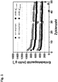
- Höhere Kapazität durch bessere Materialausnutzung bei kleineren Partikelgrößen ist sichtbar.
- Die Resultate der Messungen sind dabei in
Figur 1 dargestellt. Die dargestellten Messwerte zeigen, dass aufgrund der Verlängerung der Mahldauer sich eine geringere Li2SO4 Partikelgröße ergibt und für eine Batterie die 60 h Stunden gemahlen wurde eine um etwa 30 % erhöhte Entladekapazität (Ladungsmenge die während der Entladung aus der Batterie entnommen werden kann) als bei einer Batterie deren Li2S Aktivmaterial Precursor Li2SO4 nur 4 h gemahlen wurde. -
- gleiche Herstellung der Probe und Kathode wie Probe Bred aus Beispiel 1 (60 h Mahlung)
- Herstellung von Zelle gleich, allerdings mit anderem Elektrolyt vermessen
- ∘ 20 µl Elektrolyt (1 M LiTFSI (Aldrich, 99.95 %). 0.125 M UN03 (Alta Aesar, 99.98%, anhydrous), 0.125 M U2S6 in 50 Vol.-% DME (Sigma Aldrich, 99.5 %, anhydrous) und 50 Vol.-% DOL (Aldrich, 99.8 %, anhydrous)
- Die Zelle wurde galvanostatisch gemessen
- ∘ Ladung bei 11.7 mA g-1 Li2S bis 3.4 V
- ∘ Danach Ent-/Ladung zwischen 1.8 und 2.6 V bei 58.4 mA g-1 Li2S für 10 Zyklen
- ∘ Danach Ent-/Ladung zwischen 1.8 und 2.6 V bei 116.8 mA g-1 Li2S für 40 Zyklen
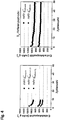
- Höhere Kapazität durch bessere Materialausnutzung durch Polysulfidadditiv.
- Die Resultate der Messungen sind dabei in
Figur 2 dargestellt. Durch den Zusatz von 0,125 mol/L Li2S6 in den Elektrolyten einer Batterie mit Lithiumsulfid-Nanopartikeln lässt sich die Entladekapazität (Ladungsmenge die während der Entladung aus der Batterie entnommen werden kann) um 16 % steigern. -
- 65,6 M.-% Li2S04.1H20 (>99 M.-% von Carl Roth) wurden mit Ruß (Ketjen Black 600JD) für 60 Stunden in einer Planetenkugelmühle (PM 100, Reisch GmbH) bei 450 rpm-1 gemahlen
∘ Mahlprogram jeweils 1 h mahlen 1 h Pause - gleiche Herstellung der Kathode und Zelle wie für Probe Bred aus Beispiel 1
- Verbesserung: sehr hohe Schwefelausnutzung erreichbar!
- Nur geringe Verbesserung bei mAh g-1 cathode
- Die Ergebnisse der Messungen sind in
Figur 3 dargestellt. Aufgrund der Verringerung der Li2S-Nanopartikel Menge in der Kathode einer Lithium-Schwefel-Batterie von 78 Gew-% Li2S (entspricht 71 Gew-% Schwefel) auf 68 Gew-% Li2S (enstpricht 60 Gew-% Schwefel) lässt sich die Entladekapazität (Ladungsmenge die während der Entladung aus der Batterie entnommen werden kann) einer solchen Batterie um etwa 17 % steigern. - Nachweis, dass Li2S Kathoden gleiche Performance zeigen wie Schwefelkathoden mit gleichem Kohlenstoffmaterial
- Schwefelkathode + Zelle:
- Eine Kathode wurde durch eine trockene Verarbeitung erstellt und auf Streckaluminium (Bender GmbH, 12 µm dick) gewalzt
∘ die Massenanteile in der Kathode waren 60 M.-% Schwefel (>99.5%, Sigma-Aldrich), 36 M.-% (Ketjen Black 600JD), und 3 M.-% PTFE (Aldrich) - Die erhaltene Kathode wurde in einer Knopfzelle (CR2016) verbaut. Die Bestandteile waren
- ∘ 12mm Schwefelkathode
- ∘ 1 Separator (Celgard 2500, 19 mm Durchmesser)
- ∘ 250 µm Lithiumfolie (MTI corp., 15 mm Durchmesser)
- ∘ 2 500 µm V2A-Stahlabstandhalter (15.4 mm Durchmesser)
- ∘ 20 µl Elektrolyt (1 M LiTFSI (Aldrich, 99.95 %), 0.25 M LiNO3 (Alta Aesar, 99.98%, anhydrous) in 50 Vol.-% DME (Sigma Aldrich, 99.5 %, anhydrous) und 50 Vol.-% DOI (Aldrich, 99.8 %, anhydrous)
- Die Zelle wurde galvanostatisch gemessen
∘ Ent-/Ladung zwischen 1.8 und 2.6 V bei 836 mA g-1 Schwefel für 50 Zyklen - Die Ergebnisse der Messungen sind in
Figur 4 dargestellt. Im direkten Vergleich mit einer Batterie deren Kathodenaktivmaterial zu 60 Gew-% aus Schwefel besteht besitzt eine Batterie deren Kathodenaktivmaterial zu 68 Gew-% aus Li2S besteht (entspricht zu 60 Gew-% Schwefel) eine ähnliche Entladekapazität (Ladungsmenge die während der Entladung aus der Batterie entnommen werden kann). - Alkalimetallsulfid-Nanopartikel können in einem diskontinuierlich oder kontinuierlich betriebenen CVD-Durchfluss- oder CVD-Wirbelschichtreaktor mittels eines gasförmigen Precursors mit einer Kohlenstoffummantelung versehen werden.
- Ofenbetriebstemperatur: 750 °C
- Eingesetzte Gase: Argon und Ethen
- Ofenbetriebsdauer: 15 - 60 min
-
- DME: 1,2-Dimethoxyethan
- DOL: 1,3-Dioxolan
- LiN03: Lithiumnitrat
- LiTFSI: Lithiumbis(trifluoromethylsulfonyl)imid
- Li2S04.1 H20: Lithiumsulfat Monohydrat
- Li2S04: Lithiumsulfat
- Li2S6: Lithiumpolysulfid mit mittlerer Schwefelkettenlänge von sechs
Claims (12)
- Verfahren zur Herstellung von Alkalimetallsulfid-Nanopartikeln, dadurch gekennzeichnet, dass bei dem Verfahren eine Mischung, enthaltend Alkalimetallsulfat-Nanopartikel und Kohlenstoff-haltigem Material erzeugt und die Mischung unterhalb der Schmelztemperatur des Alkalimetallsulfats carbothermisch reduziert wird, dadurch gekennzeichnet, dass die mittlere Teilchengröße d50 der Alkalimetallsulfat-Nanopartikel von 5 bis 100 nm beträgt.
- Verfahren nach Anspruch 1, dadurch gekennzeichnet, dass das Alkalimetall ausgewählt ist aus der Gruppe bestehend aus Lithium und/oder Natrium.
- Verfahren nach einem der vorhergehenden Ansprüche, dadurch gekennzeichnet, dass das Kohlenstoff-enthaltende Material ausgewählt ist aus der Gruppe bestehend aus Ruß, porösen Kohlenstoffen, Kohlenstoffnanoröhrchen, Graphit, Graphen, Kohlenstofffasern sowie Mischungen oder Kombinationen hieraus, und/oder die Alkalimetallsulfat-Nanopartikel mit dem Kohlenstoff enthaltenden Material in einem Gewichtsverhältnis von 20:100 bis 100:100, bevorzugt von 30:100 bis 75:100, weiter bevorzugt von 53:100 bis 73:100, weiter bevorzugt von 62:100 bis 69:100 eingesetzt wird.
- Verfahren nach einem der vorhergehenden Ansprüche, dadurch gekennzeichnet, dass die Mischunga) durch Mahlen von Alkalimetallsulfat mit dem Kohlenstoff enthaltenden Material, insbesondere durch Mahlen in einer Kugelmühle,b) durch Fällung von Alkalimetallsulfat-Nanopartikel in Gegenwart des Kohlenstoff enthaltenden Materials, oderc) durch Infiltration einer Alkalimetallsulfat-Lösung in poröse Kohlenstoffmaterialienerzeugt wird.
- Verfahren nach einem der vorhergehenden Ansprüche, dadurch gekennzeichnet, dass die carbothermische Reduktioni) bei Temperaturen von 500 bis 880 °C, bevorzugt von 600 bis 860 °C, weiter bevorzugt von 650 bis 840 °C, besonders bevorzugt von 700 bis 830 °C durchgeführt wird; und/oderii) über einen Zeitraum von 0,2 bis 48 h, bevorzugt von 2 bis 4 h durchgeführt wird; und/oderiii) unter einer Inertgasatmosphäre, insbesondere unter einer Argon- und/oder Stickstoffatmosphäre durchgeführt wird.
- Verfahren nach einem der vorhergehenden Ansprüche, dadurch gekennzeichnet, dass nach erfolgter carbothermischer Reduktion die Alkalimetallsulfid-Nanopartikel mit einer aus Kohlenstoff bestehenden oder Kohlenstoff enthaltenden Schale ummantelt werden.
- Verfahren nach vorhergehendem Anspruch, dadurch gekennzeichnet, dass zur Ummantelung mindestens ein Kohlenstoff enthaltender Precursor, insbesondere ein gasförmiger und/oder flüssiger Precursor oder ein Precursor in Lösung eingesetzt wird, der mit den Alkalimetallsulfid-Nanopartikeln kontaktiert und aus dem nach erfolgter Kontaktierung die Kohlenstoff enthaltenden Hülle abgeschieden wird.
- Verfahren nach vorhergehendem Anspruch, dadurch gekennzeichnet, dass der mindestens eine gasförmige Precursor ausgewählt ist aus der Gruppe bestehend aus bei Normalbedingungen gasförmigen Kohlenwasserstoffen, bevorzugt ungesättigten gasförmigen Kohlenwasserstoffen, insbesondere Ethin, Ethen, Propen sowie Mischungen hieraus und/oder der mindestens eine flüssige Precursor ausgewählt ist aus der Gruppe bestehend aus Pech und/oder Steinkohleteer oder organischen Polymeren und/oder organischen Polymerisations-Monomeren in flüssiger Phase oder als Lösung.
- Alkalimetallsulfid-Nanopartikel, herstellbar nach einem Verfahren nach einem der vorhergehenden Ansprüche, wobei die Alkalimetallsulfid-Nanopartikel einen Kern aus Alkalimetallsulfid sowie eine aus Kohlenstoff bestehende oder Kohlenstoff enthaltende Schale aufweisen, dadurch gekennzeichnet, dass ihre mittlere Teilchengröße d50 zwischen 5 und 100 nm beträgt und die Schale eine Dicke von 2 bis 20 nm aufweist.
- Verwendung der Alkalimetallsulfid-Nanopartikel nach Anspruch 9 als Kathodenmaterial für Alkalimetall-Schwefel-Batterien.
- Alkalimetall-Schwefel-Batterie, umfassend eine Kathode, enthaltend Alkalimetallsulfid-Nanopartikel nach Anspruch 9.
- Alkalimetall-Schwefel-Batterie nach vorhergehendem Anspruch, dadurch gekennzeichnet, dass die Kathode ein Kathodenmaterial umfasst, das zumindest teilweise fibrilliertes Polytetrafluorethylen sowie Alkalimetallsulfid-Nanopartikel als elektrochemisch aktives Kathodenmaterial aufweist.
Applications Claiming Priority (2)
| Application Number | Priority Date | Filing Date | Title |
|---|---|---|---|
| DE102014211421.7A DE102014211421A1 (de) | 2014-06-13 | 2014-06-13 | Verfahren zur Herstellung von Alkalimetallsulfid-Nanopartikeln, Alkalimetallsulfid-Nanopartikel, Verwendung der Alkalimetallsulfid-Nanopartikel sowie Alkalimetall-Schwefel-Batterie |
| PCT/EP2015/061970 WO2015189053A1 (de) | 2014-06-13 | 2015-05-29 | Verfahren zur herstellung von alkalimetallsulfid-nanopartikeln, alkalimetallsulfid-nanopartikel, verwendung der alkalimetallsulfid-nanopartikel sowie alkalimetall-schwefel-batterie |
Publications (2)
| Publication Number | Publication Date |
|---|---|
| EP3155678A1 EP3155678A1 (de) | 2017-04-19 |
| EP3155678B1 true EP3155678B1 (de) | 2019-09-11 |
Family
ID=53398043
Family Applications (1)
| Application Number | Title | Priority Date | Filing Date |
|---|---|---|---|
| EP15729092.5A Active EP3155678B1 (de) | 2014-06-13 | 2015-05-29 | Verfahren zur herstellung von alkalimetallsulfid-nanopartikeln, alkalimetallsulfid-nanopartikel, verwendung der alkalimetallsulfid-nanopartikel sowie alkalimetall-schwefel-batterie |
Country Status (3)
| Country | Link |
|---|---|
| EP (1) | EP3155678B1 (de) |
| DE (1) | DE102014211421A1 (de) |
| WO (1) | WO2015189053A1 (de) |
Families Citing this family (8)
| Publication number | Priority date | Publication date | Assignee | Title |
|---|---|---|---|---|
| CN110002407B (zh) * | 2018-01-05 | 2022-07-19 | 武汉大学 | 一种碳热反应合成金属硫化物的方法 |
| CN109473647A (zh) * | 2018-11-01 | 2019-03-15 | 东莞市迈科新能源有限公司 | 一种锂硫电池正极材料及其制备方法 |
| US20220096539A1 (en) * | 2019-01-18 | 2022-03-31 | University Of Georgia Research Foundation, Inc. | Salt nanoparticles and compositions and methods of use thereof |
| CN110247047B (zh) * | 2019-07-23 | 2022-06-07 | 福州大学 | 一种锂硫电池正极材料及其制备方法 |
| CN113793933B (zh) * | 2021-09-10 | 2023-05-30 | 深圳市研一新材料有限责任公司 | 一种固态电解质用硫化锂及其制备方法和应用 |
| CN114583127B (zh) * | 2022-02-28 | 2023-05-09 | 南京工业大学 | 一种制备CoNi-S@3D-C纳米复合材料和改性电池隔膜的方法 |
| CN115241363B (zh) * | 2022-07-11 | 2025-06-03 | 上海应用技术大学 | MoSe2@C/PEDOT:PSS复合热电薄膜的制备方法 |
| CN117977044B (zh) * | 2024-04-01 | 2024-07-16 | 四川新能源汽车创新中心有限公司 | 一种硫化物基全固态电池物料的回收方法 |
Family Cites Families (10)
| Publication number | Priority date | Publication date | Assignee | Title |
|---|---|---|---|---|
| US2840455A (en) | 1953-12-02 | 1958-06-24 | Tholand Inc | Production of lithium carbonate |
| JP3510420B2 (ja) | 1996-04-16 | 2004-03-29 | 松下電器産業株式会社 | リチウムイオン伝導性固体電解質およびその製造方法 |
| GB2351075A (en) | 1999-06-17 | 2000-12-20 | Secr Defence | Producing lithiated transition metal sulphides |
| JP4948659B1 (ja) * | 2011-04-12 | 2012-06-06 | 三井金属鉱業株式会社 | リチウムイオン電池固体電解質材料用硫化リチウムの製造方法 |
| KR101997261B1 (ko) * | 2011-12-23 | 2019-07-08 | 현대자동차주식회사 | 유황 다공성 나노복합구조체와 다공성 나노도전재를 함유한 리튬 유황 이차전지용 양극 |
| DE102012203019A1 (de) | 2012-02-28 | 2013-08-29 | Technische Universität Dresden | Kathode für Lithium-haltige Batterien und lösungsmittelfreies Verfahren zu deren Herstellung |
| JP5770675B2 (ja) * | 2012-04-26 | 2015-08-26 | 古河機械金属株式会社 | 硫化リチウムの製造方法 |
| JP6059449B2 (ja) * | 2012-04-26 | 2017-01-11 | 古河機械金属株式会社 | 二次電池用正極材料の製造方法、二次電池用正極の製造方法および二次電池の製造方法 |
| DE102012018622A1 (de) * | 2012-09-14 | 2014-03-20 | Fraunhofer-Gesellschaft zur Förderung der angewandten Forschung e.V. | Li-S-Batterie mit hoher Zyklenstabilität und Verfahren zu deren Betreiben |
| US10505180B2 (en) * | 2012-11-07 | 2019-12-10 | The Regents Of The University Of California | Core-shell structured nanoparticles for lithium-sulfur cells |
-
2014
- 2014-06-13 DE DE102014211421.7A patent/DE102014211421A1/de not_active Ceased
-
2015
- 2015-05-29 WO PCT/EP2015/061970 patent/WO2015189053A1/de not_active Ceased
- 2015-05-29 EP EP15729092.5A patent/EP3155678B1/de active Active
Non-Patent Citations (1)
| Title |
|---|
| None * |
Also Published As
| Publication number | Publication date |
|---|---|
| WO2015189053A1 (de) | 2015-12-17 |
| DE102014211421A1 (de) | 2015-12-17 |
| EP3155678A1 (de) | 2017-04-19 |
Similar Documents
| Publication | Publication Date | Title |
|---|---|---|
| Yen et al. | Interface engineering of high entropy Oxide@ Polyaniline heterojunction enables highly stable and excellent lithium ion storage performance | |
| Yuan et al. | Improvement of cycle property of sulfur-coated multi-walled carbon nanotubes composite cathode for lithium/sulfur batteries | |
| WO2015189053A1 (de) | Verfahren zur herstellung von alkalimetallsulfid-nanopartikeln, alkalimetallsulfid-nanopartikel, verwendung der alkalimetallsulfid-nanopartikel sowie alkalimetall-schwefel-batterie | |
| DE69529150T2 (de) | Wiederaufladbare Postitivelektrode | |
| DE69701202T2 (de) | Nichtwässrige Sekundärbatterie und Verfahren zur Herstellung eines activen Materials for eine negative Electrode | |
| DE69900058T2 (de) | Feste Lithium-Sekundärbatterie | |
| DE69324780T2 (de) | Elektrochemische Zelle | |
| Ahmad et al. | SnO2/ZnO composite structure for the lithium-ion battery electrode | |
| EP2769427B1 (de) | Aktivmaterial für batterien | |
| EP2417655B1 (de) | Kathodenmaterial für fluoridbasierte konversionselektroden, verfahren zu seiner herstellung und seine verwendung | |
| DE69606106T2 (de) | Negative aktive Masse geeignet für ungesinterte Nickelelektroden für alkalische Akkumulatoren | |
| DE69605617T2 (de) | Lithiumsekundärbatterie mit nichtwässrigem Elektrolyt | |
| EP2573845B1 (de) | Strukturstabiles Aktivmaterial für Batterieelektroden | |
| DE69702293T2 (de) | Sekundärbatterie mit nichtwässrigem Elektrolyten | |
| DE69609766T2 (de) | Material zur Verwendung in positiven Elektroden von Lithiumbatterien; dessen Herstellung und dieses Material enthaltende Lithiumbatterien | |
| DE69706592T2 (de) | Verfahren zur Herstellung von positivelektrode-aktivem Material, sowie diese verwendende nichtwässerige Sekundärbatterie | |
| Wang et al. | Preparation of Sn2Sb alloy encapsulated carbon microsphere anode materials for Li-ion batteries by carbothermal reduction of the oxides | |
| DE102023121567A1 (de) | Anodenlose festkörper-batterie, welche eine verbundstrukturschicht aufweist, und herstellungsverfahren dafür | |
| DE102021129277A1 (de) | Negativelektroden-aktivmaterial umfassend einen kern-schalen-verbundstoff und verfahren zur dessen herstellung | |
| DE69518476T2 (de) | Nichtwässrige Sekundärbatterie und Negativelektrode | |
| DE69836462T2 (de) | Sekundärbatterie | |
| Gandi et al. | SnO-GeO2-Sb2O3 glass anode network mixed with different Ba2+ fractions: investigations on Na-ion storage capacity and stability | |
| Fu et al. | Electrochemical properties of Cu2S with ether-based electrolyte in Li-ion batteries | |
| DE102014221782A1 (de) | Lithiumbatterie | |
| DE102020131337A1 (de) | Festkörperbatterie aufweisend eine elektrolytschicht mit aussparungsmuster |
Legal Events
| Date | Code | Title | Description |
|---|---|---|---|
| STAA | Information on the status of an ep patent application or granted ep patent |
Free format text: STATUS: THE INTERNATIONAL PUBLICATION HAS BEEN MADE |
|
| PUAI | Public reference made under article 153(3) epc to a published international application that has entered the european phase |
Free format text: ORIGINAL CODE: 0009012 |
|
| STAA | Information on the status of an ep patent application or granted ep patent |
Free format text: STATUS: REQUEST FOR EXAMINATION WAS MADE |
|
| 17P | Request for examination filed |
Effective date: 20161221 |
|
| AK | Designated contracting states |
Kind code of ref document: A1 Designated state(s): AL AT BE BG CH CY CZ DE DK EE ES FI FR GB GR HR HU IE IS IT LI LT LU LV MC MK MT NL NO PL PT RO RS SE SI SK SM TR |
|
| AX | Request for extension of the european patent |
Extension state: BA ME |
|
| DAV | Request for validation of the european patent (deleted) | ||
| DAX | Request for extension of the european patent (deleted) | ||
| STAA | Information on the status of an ep patent application or granted ep patent |
Free format text: STATUS: EXAMINATION IS IN PROGRESS |
|
| 17Q | First examination report despatched |
Effective date: 20171026 |
|
| GRAP | Despatch of communication of intention to grant a patent |
Free format text: ORIGINAL CODE: EPIDOSNIGR1 |
|
| STAA | Information on the status of an ep patent application or granted ep patent |
Free format text: STATUS: GRANT OF PATENT IS INTENDED |
|
| INTG | Intention to grant announced |
Effective date: 20190226 |
|
| GRAS | Grant fee paid |
Free format text: ORIGINAL CODE: EPIDOSNIGR3 |
|
| GRAJ | Information related to disapproval of communication of intention to grant by the applicant or resumption of examination proceedings by the epo deleted |
Free format text: ORIGINAL CODE: EPIDOSDIGR1 |
|
| GRAL | Information related to payment of fee for publishing/printing deleted |
Free format text: ORIGINAL CODE: EPIDOSDIGR3 |
|
| STAA | Information on the status of an ep patent application or granted ep patent |
Free format text: STATUS: EXAMINATION IS IN PROGRESS |
|
| GRAR | Information related to intention to grant a patent recorded |
Free format text: ORIGINAL CODE: EPIDOSNIGR71 |
|
| STAA | Information on the status of an ep patent application or granted ep patent |
Free format text: STATUS: GRANT OF PATENT IS INTENDED |
|
| GRAA | (expected) grant |
Free format text: ORIGINAL CODE: 0009210 |
|
| STAA | Information on the status of an ep patent application or granted ep patent |
Free format text: STATUS: THE PATENT HAS BEEN GRANTED |
|
| INTC | Intention to grant announced (deleted) | ||
| INTG | Intention to grant announced |
Effective date: 20190731 |
|
| AK | Designated contracting states |
Kind code of ref document: B1 Designated state(s): AL AT BE BG CH CY CZ DE DK EE ES FI FR GB GR HR HU IE IS IT LI LT LU LV MC MK MT NL NO PL PT RO RS SE SI SK SM TR |
|
| REG | Reference to a national code |
Ref country code: GB Ref legal event code: FG4D Free format text: NOT ENGLISH |
|
| REG | Reference to a national code |
Ref country code: CH Ref legal event code: EP |
|
| REG | Reference to a national code |
Ref country code: AT Ref legal event code: REF Ref document number: 1179652 Country of ref document: AT Kind code of ref document: T Effective date: 20190915 |
|
| REG | Reference to a national code |
Ref country code: DE Ref legal event code: R096 Ref document number: 502015010327 Country of ref document: DE Ref country code: IE Ref legal event code: FG4D Free format text: LANGUAGE OF EP DOCUMENT: GERMAN |
|
| REG | Reference to a national code |
Ref country code: NL Ref legal event code: MP Effective date: 20190911 |
|
| REG | Reference to a national code |
Ref country code: LT Ref legal event code: MG4D |
|
| PG25 | Lapsed in a contracting state [announced via postgrant information from national office to epo] |
Ref country code: NO Free format text: LAPSE BECAUSE OF FAILURE TO SUBMIT A TRANSLATION OF THE DESCRIPTION OR TO PAY THE FEE WITHIN THE PRESCRIBED TIME-LIMIT Effective date: 20191211 Ref country code: BG Free format text: LAPSE BECAUSE OF FAILURE TO SUBMIT A TRANSLATION OF THE DESCRIPTION OR TO PAY THE FEE WITHIN THE PRESCRIBED TIME-LIMIT Effective date: 20191211 Ref country code: SE Free format text: LAPSE BECAUSE OF FAILURE TO SUBMIT A TRANSLATION OF THE DESCRIPTION OR TO PAY THE FEE WITHIN THE PRESCRIBED TIME-LIMIT Effective date: 20190911 Ref country code: FI Free format text: LAPSE BECAUSE OF FAILURE TO SUBMIT A TRANSLATION OF THE DESCRIPTION OR TO PAY THE FEE WITHIN THE PRESCRIBED TIME-LIMIT Effective date: 20190911 Ref country code: HR Free format text: LAPSE BECAUSE OF FAILURE TO SUBMIT A TRANSLATION OF THE DESCRIPTION OR TO PAY THE FEE WITHIN THE PRESCRIBED TIME-LIMIT Effective date: 20190911 Ref country code: LT Free format text: LAPSE BECAUSE OF FAILURE TO SUBMIT A TRANSLATION OF THE DESCRIPTION OR TO PAY THE FEE WITHIN THE PRESCRIBED TIME-LIMIT Effective date: 20190911 |
|
| PG25 | Lapsed in a contracting state [announced via postgrant information from national office to epo] |
Ref country code: AL Free format text: LAPSE BECAUSE OF FAILURE TO SUBMIT A TRANSLATION OF THE DESCRIPTION OR TO PAY THE FEE WITHIN THE PRESCRIBED TIME-LIMIT Effective date: 20190911 Ref country code: ES Free format text: LAPSE BECAUSE OF FAILURE TO SUBMIT A TRANSLATION OF THE DESCRIPTION OR TO PAY THE FEE WITHIN THE PRESCRIBED TIME-LIMIT Effective date: 20190911 Ref country code: GR Free format text: LAPSE BECAUSE OF FAILURE TO SUBMIT A TRANSLATION OF THE DESCRIPTION OR TO PAY THE FEE WITHIN THE PRESCRIBED TIME-LIMIT Effective date: 20191212 Ref country code: RS Free format text: LAPSE BECAUSE OF FAILURE TO SUBMIT A TRANSLATION OF THE DESCRIPTION OR TO PAY THE FEE WITHIN THE PRESCRIBED TIME-LIMIT Effective date: 20190911 Ref country code: LV Free format text: LAPSE BECAUSE OF FAILURE TO SUBMIT A TRANSLATION OF THE DESCRIPTION OR TO PAY THE FEE WITHIN THE PRESCRIBED TIME-LIMIT Effective date: 20190911 |
|
| PG25 | Lapsed in a contracting state [announced via postgrant information from national office to epo] |
Ref country code: PT Free format text: LAPSE BECAUSE OF FAILURE TO SUBMIT A TRANSLATION OF THE DESCRIPTION OR TO PAY THE FEE WITHIN THE PRESCRIBED TIME-LIMIT Effective date: 20200113 Ref country code: PL Free format text: LAPSE BECAUSE OF FAILURE TO SUBMIT A TRANSLATION OF THE DESCRIPTION OR TO PAY THE FEE WITHIN THE PRESCRIBED TIME-LIMIT Effective date: 20190911 Ref country code: NL Free format text: LAPSE BECAUSE OF FAILURE TO SUBMIT A TRANSLATION OF THE DESCRIPTION OR TO PAY THE FEE WITHIN THE PRESCRIBED TIME-LIMIT Effective date: 20190911 Ref country code: RO Free format text: LAPSE BECAUSE OF FAILURE TO SUBMIT A TRANSLATION OF THE DESCRIPTION OR TO PAY THE FEE WITHIN THE PRESCRIBED TIME-LIMIT Effective date: 20190911 Ref country code: IT Free format text: LAPSE BECAUSE OF FAILURE TO SUBMIT A TRANSLATION OF THE DESCRIPTION OR TO PAY THE FEE WITHIN THE PRESCRIBED TIME-LIMIT Effective date: 20190911 Ref country code: EE Free format text: LAPSE BECAUSE OF FAILURE TO SUBMIT A TRANSLATION OF THE DESCRIPTION OR TO PAY THE FEE WITHIN THE PRESCRIBED TIME-LIMIT Effective date: 20190911 |
|
| PG25 | Lapsed in a contracting state [announced via postgrant information from national office to epo] |
Ref country code: CZ Free format text: LAPSE BECAUSE OF FAILURE TO SUBMIT A TRANSLATION OF THE DESCRIPTION OR TO PAY THE FEE WITHIN THE PRESCRIBED TIME-LIMIT Effective date: 20190911 Ref country code: SM Free format text: LAPSE BECAUSE OF FAILURE TO SUBMIT A TRANSLATION OF THE DESCRIPTION OR TO PAY THE FEE WITHIN THE PRESCRIBED TIME-LIMIT Effective date: 20190911 Ref country code: IS Free format text: LAPSE BECAUSE OF FAILURE TO SUBMIT A TRANSLATION OF THE DESCRIPTION OR TO PAY THE FEE WITHIN THE PRESCRIBED TIME-LIMIT Effective date: 20200224 Ref country code: SK Free format text: LAPSE BECAUSE OF FAILURE TO SUBMIT A TRANSLATION OF THE DESCRIPTION OR TO PAY THE FEE WITHIN THE PRESCRIBED TIME-LIMIT Effective date: 20190911 |
|
| REG | Reference to a national code |
Ref country code: DE Ref legal event code: R097 Ref document number: 502015010327 Country of ref document: DE |
|
| PLBE | No opposition filed within time limit |
Free format text: ORIGINAL CODE: 0009261 |
|
| STAA | Information on the status of an ep patent application or granted ep patent |
Free format text: STATUS: NO OPPOSITION FILED WITHIN TIME LIMIT |
|
| PG2D | Information on lapse in contracting state deleted |
Ref country code: IS |
|
| PG25 | Lapsed in a contracting state [announced via postgrant information from national office to epo] |
Ref country code: DK Free format text: LAPSE BECAUSE OF FAILURE TO SUBMIT A TRANSLATION OF THE DESCRIPTION OR TO PAY THE FEE WITHIN THE PRESCRIBED TIME-LIMIT Effective date: 20190911 Ref country code: IS Free format text: LAPSE BECAUSE OF FAILURE TO SUBMIT A TRANSLATION OF THE DESCRIPTION OR TO PAY THE FEE WITHIN THE PRESCRIBED TIME-LIMIT Effective date: 20200112 |
|
| 26N | No opposition filed |
Effective date: 20200615 |
|
| PG25 | Lapsed in a contracting state [announced via postgrant information from national office to epo] |
Ref country code: SI Free format text: LAPSE BECAUSE OF FAILURE TO SUBMIT A TRANSLATION OF THE DESCRIPTION OR TO PAY THE FEE WITHIN THE PRESCRIBED TIME-LIMIT Effective date: 20190911 |
|
| PG25 | Lapsed in a contracting state [announced via postgrant information from national office to epo] |
Ref country code: MC Free format text: LAPSE BECAUSE OF FAILURE TO SUBMIT A TRANSLATION OF THE DESCRIPTION OR TO PAY THE FEE WITHIN THE PRESCRIBED TIME-LIMIT Effective date: 20190911 Ref country code: CH Free format text: LAPSE BECAUSE OF NON-PAYMENT OF DUE FEES Effective date: 20200531 Ref country code: LI Free format text: LAPSE BECAUSE OF NON-PAYMENT OF DUE FEES Effective date: 20200531 |
|
| REG | Reference to a national code |
Ref country code: BE Ref legal event code: MM Effective date: 20200531 |
|
| PG25 | Lapsed in a contracting state [announced via postgrant information from national office to epo] |
Ref country code: LU Free format text: LAPSE BECAUSE OF NON-PAYMENT OF DUE FEES Effective date: 20200529 |
|
| PG25 | Lapsed in a contracting state [announced via postgrant information from national office to epo] |
Ref country code: IE Free format text: LAPSE BECAUSE OF NON-PAYMENT OF DUE FEES Effective date: 20200529 |
|
| PG25 | Lapsed in a contracting state [announced via postgrant information from national office to epo] |
Ref country code: BE Free format text: LAPSE BECAUSE OF NON-PAYMENT OF DUE FEES Effective date: 20200531 |
|
| PG25 | Lapsed in a contracting state [announced via postgrant information from national office to epo] |
Ref country code: TR Free format text: LAPSE BECAUSE OF FAILURE TO SUBMIT A TRANSLATION OF THE DESCRIPTION OR TO PAY THE FEE WITHIN THE PRESCRIBED TIME-LIMIT Effective date: 20190911 Ref country code: MT Free format text: LAPSE BECAUSE OF FAILURE TO SUBMIT A TRANSLATION OF THE DESCRIPTION OR TO PAY THE FEE WITHIN THE PRESCRIBED TIME-LIMIT Effective date: 20190911 Ref country code: CY Free format text: LAPSE BECAUSE OF FAILURE TO SUBMIT A TRANSLATION OF THE DESCRIPTION OR TO PAY THE FEE WITHIN THE PRESCRIBED TIME-LIMIT Effective date: 20190911 |
|
| PG25 | Lapsed in a contracting state [announced via postgrant information from national office to epo] |
Ref country code: MK Free format text: LAPSE BECAUSE OF FAILURE TO SUBMIT A TRANSLATION OF THE DESCRIPTION OR TO PAY THE FEE WITHIN THE PRESCRIBED TIME-LIMIT Effective date: 20190911 |
|
| P01 | Opt-out of the competence of the unified patent court (upc) registered |
Effective date: 20230524 |
|
| PGFP | Annual fee paid to national office [announced via postgrant information from national office to epo] |
Ref country code: DE Payment date: 20250519 Year of fee payment: 11 |
|
| PGFP | Annual fee paid to national office [announced via postgrant information from national office to epo] |
Ref country code: GB Payment date: 20250522 Year of fee payment: 11 |
|
| PGFP | Annual fee paid to national office [announced via postgrant information from national office to epo] |
Ref country code: FR Payment date: 20250521 Year of fee payment: 11 |
|
| PGFP | Annual fee paid to national office [announced via postgrant information from national office to epo] |
Ref country code: AT Payment date: 20250519 Year of fee payment: 11 |