EP3154869B1 - Abdeckvorrichtung für einen trinkbehälter - Google Patents
Abdeckvorrichtung für einen trinkbehälter Download PDFInfo
- Publication number
- EP3154869B1 EP3154869B1 EP15725067.1A EP15725067A EP3154869B1 EP 3154869 B1 EP3154869 B1 EP 3154869B1 EP 15725067 A EP15725067 A EP 15725067A EP 3154869 B1 EP3154869 B1 EP 3154869B1
- Authority
- EP
- European Patent Office
- Prior art keywords
- valve element
- ring
- sleeve
- shaped member
- cover device
- Prior art date
- Legal status (The legal status is an assumption and is not a legal conclusion. Google has not performed a legal analysis and makes no representation as to the accuracy of the status listed.)
- Active
Links
Images

Classifications
-
- B—PERFORMING OPERATIONS; TRANSPORTING
- B65—CONVEYING; PACKING; STORING; HANDLING THIN OR FILAMENTARY MATERIAL
- B65D—CONTAINERS FOR STORAGE OR TRANSPORT OF ARTICLES OR MATERIALS, e.g. BAGS, BARRELS, BOTTLES, BOXES, CANS, CARTONS, CRATES, DRUMS, JARS, TANKS, HOPPERS, FORWARDING CONTAINERS; ACCESSORIES, CLOSURES, OR FITTINGS THEREFOR; PACKAGING ELEMENTS; PACKAGES
- B65D47/00—Closures with filling and discharging, or with discharging, devices
- B65D47/04—Closures with discharging devices other than pumps
- B65D47/20—Closures with discharging devices other than pumps comprising hand-operated members for controlling discharge
- B65D47/2018—Closures with discharging devices other than pumps comprising hand-operated members for controlling discharge comprising a valve or like element which is opened or closed by deformation of the container or closure
- B65D47/2031—Closures with discharging devices other than pumps comprising hand-operated members for controlling discharge comprising a valve or like element which is opened or closed by deformation of the container or closure the element being formed by a slit, narrow opening or constrictable spout, the size of the outlet passage being able to be varied by increasing or decreasing the pressure
-
- A—HUMAN NECESSITIES
- A47—FURNITURE; DOMESTIC ARTICLES OR APPLIANCES; COFFEE MILLS; SPICE MILLS; SUCTION CLEANERS IN GENERAL
- A47G—HOUSEHOLD OR TABLE EQUIPMENT
- A47G19/00—Table service
- A47G19/22—Drinking vessels or saucers used for table service
- A47G19/2205—Drinking glasses or vessels
- A47G19/2266—Means for facilitating drinking, e.g. for infants or invalids
- A47G19/2272—Means for facilitating drinking, e.g. for infants or invalids from drinking glasses or cups comprising lids or covers
-
- B—PERFORMING OPERATIONS; TRANSPORTING
- B65—CONVEYING; PACKING; STORING; HANDLING THIN OR FILAMENTARY MATERIAL
- B65D—CONTAINERS FOR STORAGE OR TRANSPORT OF ARTICLES OR MATERIALS, e.g. BAGS, BARRELS, BOTTLES, BOXES, CANS, CARTONS, CRATES, DRUMS, JARS, TANKS, HOPPERS, FORWARDING CONTAINERS; ACCESSORIES, CLOSURES, OR FITTINGS THEREFOR; PACKAGING ELEMENTS; PACKAGES
- B65D43/00—Lids or covers for rigid or semi-rigid containers
- B65D43/02—Removable lids or covers
- B65D43/0202—Removable lids or covers without integral tamper element
- B65D43/0225—Removable lids or covers without integral tamper element secured by rotation
-
- B—PERFORMING OPERATIONS; TRANSPORTING
- B65—CONVEYING; PACKING; STORING; HANDLING THIN OR FILAMENTARY MATERIAL
- B65D—CONTAINERS FOR STORAGE OR TRANSPORT OF ARTICLES OR MATERIALS, e.g. BAGS, BARRELS, BOTTLES, BOXES, CANS, CARTONS, CRATES, DRUMS, JARS, TANKS, HOPPERS, FORWARDING CONTAINERS; ACCESSORIES, CLOSURES, OR FITTINGS THEREFOR; PACKAGING ELEMENTS; PACKAGES
- B65D47/00—Closures with filling and discharging, or with discharging, devices
- B65D47/04—Closures with discharging devices other than pumps
- B65D47/06—Closures with discharging devices other than pumps with pouring spouts or tubes; with discharge nozzles or passages
-
- B—PERFORMING OPERATIONS; TRANSPORTING
- B65—CONVEYING; PACKING; STORING; HANDLING THIN OR FILAMENTARY MATERIAL
- B65D—CONTAINERS FOR STORAGE OR TRANSPORT OF ARTICLES OR MATERIALS, e.g. BAGS, BARRELS, BOTTLES, BOXES, CANS, CARTONS, CRATES, DRUMS, JARS, TANKS, HOPPERS, FORWARDING CONTAINERS; ACCESSORIES, CLOSURES, OR FITTINGS THEREFOR; PACKAGING ELEMENTS; PACKAGES
- B65D47/00—Closures with filling and discharging, or with discharging, devices
- B65D47/04—Closures with discharging devices other than pumps
- B65D47/20—Closures with discharging devices other than pumps comprising hand-operated members for controlling discharge
Definitions
- the present invention relates to a cover device for a drink container, comprising a basic assembly having a drink opening, and a valve arrangement.
- the valve arrangement is associated with the basic assembly, and is adapted to assume various states for determining an extent to which a passage to the drink opening in the basic assembly from a side of the cover device which is intended to face the drink container is blocked.
- the present invention also relates to an assembly of a drink container and a cover device as mentioned, wherein the cover device is removably attached to the drink container.
- WO 2014/086625 describes a cover device for a drink container comprising a basic assembly which is provided with a drink opening and a valve arrangement for blocking or unblocking a passage to the drink opening from a drink container side of the cover device.
- the valve arrangement comprises a valve element having two portions which are connected to each other through an area of the valve element at a position where the valve element is hingably associated with the basic assembly, and wherein only one of the two portions is in direct communication with the drink opening of the basic assembly, so that a smallest total moment of force may be realized on the one portion when the valve element is subjected to pressure from the drink container side of the cover device.
- a slit is present which will open upon suction force.
- the thin material of the valve element at the location of the slit deforms when overpressure is present in the drink container on the valve element, sometimes resulting in opening of the slit. Overpressure occurs e.g. when the drink container is held upside down or is shaken.
- the cover device according to the present invention is defined by claim 1. Therefore the circumference of the ring-shaped member.
- the sleeve can enclose the ring-shaped member.
- the sleeve can also be enclosed by the ring-shaped member. In this way a fluid tight seal between the sleeve and the ring-shaped member is achieved to prevent leakage of fluid from the container to the drink opening.
- the sleeve comprises a first diameter and a second diameter.
- the ring-shaped member comprises a first diameter and a second diameter as well. Both first diameters are in the direction of the slit and both second diameters are perpendicular to the slit and to the first diameters.
- the ratio between the first and second diameters of the sleeve is smaller than the ratio between the first and second diameters of the ring-shaped member. Consequently, during assembly the sleeve is stretched or widened in the direction of first diameter and compressed or narrowed in the direction of second diameter perpendicular to the first diameter. Because the slit is oriented on the valve element and in the direction of the first diameter of the sleeve, the slit is prestressed, when the sleeve is mounted onto to the ring-shaped member: the slit is stretched in the longitudinal direction along the first diameter of the sleeve and, consequently compressed in the direction of the second diameter of the sleeve. The sides of the slit are compressed against each other. The prestressing of the slit increases the threshold value for the slit to open. This increases the leak resistance of the slit and of the valve element.
- the ring-shaped member is circular while the first diameter of the sleeve is smaller than the second diameter of the sleeve.
- the sleeve is mounted onto the ring-shaped member. Because the first diameter of the sleeve is smaller than the first diameter of the ringshaped member, which is equal to the second diameter of the ringshaped portion, the sleeve is stretched along its first diameter during assembly. The slit, which is oriented in the direction of the first diameter, is consequently stretched en prestressed in the direction of the first diameter. The stretching and prestressing of the slit increases the threshold value for the slit to open.
- This arrangement is advantageous for a user as he does not have to check upon assembly how to orient the valve element with respect to the basic assembly, because the tangential orientation of the valve element with repect to the basic assembly is not relevant: the slit will be prestressed at any orientation with respect to the ring-shaped member.
- the sleeve is circular while the first diameter of the ring-shaped member exceeds the second diameter of the ring-shaped member.
- the sleeve may be circular to match the circular shape of the valve element and/or the valve arrangement.
- a circular shape is less complicated to manufacture than a non-circular shape, e.g. the mold used for injection moulding may be easier to manufacture.
- the first diameter of the sleeve which is equal to the second diameter of the sleeve, is smaller than the first diameter of the ringshaped portion, the sleeve is stretched along its first diameter during assembly.
- the slit which is oriented in the direction of the first diameter, is consequently stretched en prestressed in the direction of the first diameter. The stretching and prestressing of the slit increases the threshold value for the slit to open.
- An assembly of a drink container and a cover device is also provided.
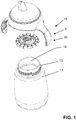
- Figs. 1-6 relate to a cover device 5 according to an embodiment of the present invention.
- the cover device 5 is intended to be used for covering an open side 12 of a drink container such as a drink bottle 11, wherein the cover device 5 has a function in avoiding spillage of liquid from the drink container 11.
- the cover device 5 is not just a cover having a sealing function.
- the cover device 5 comprises a valve arrangement 20 which is adapted to prevent liquid from flowing from an interior of the drink container 11 to outside of the drink container 11 through the cover device 5 in a closed state, and to allow a flow of liquid to pass through in an open state.
- the cover device 1 comprises a housing 30 and a spout 31 which projects from the housing 30, wherein the spout 31 comprises at least one drink opening 32 and is intended to be inserted into the mouth of the user. It is noted that an assembly of the housing 30 and the spout 31 is also referred to as basic assembly 9 of the cover device 5.
- an underpressure is obtained in the spout 31 as a result thereof, which causes the valve arrangement 20 to open and allow the drink to pass from the drink container 11 to the user's mouth, wherein it is assumed that the user keeps the drink container 11 in a tilted orientation so that the drink is present at the location of the cover device 1.
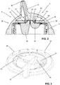
- Fig. 2 illustrates how the valve arrangement 20 is positioned in the cover device 5.
- the cover device 5 and the drink container 11 can be provided with any suitable type of means for allowing the cover device 5 and the drink container 11 to be attached to each other or to be detached from each other, depending on the user's desires.
- both the cover device 5 and the drink container 11 can be provided with screw thread, wherein the drink container 11 can be provided with external screw thread 13 as shown in Fig. 1 , and wherein the housing 30 of the cover device 1 can provided with internal screw thread for engaging with the external screw thread 13 of the drink container 11.
- the cover device 5 comprises a basic assembly 9 including a housing 30 and a pout 31, which comprises at least one drink opening 32, and a valve arrangement 20.
- the valve arrangement 20 comprises a valve element 26.
- the housing 30 comprises a ring-shaped member 37 which serves for locally supporting the valve element 26 at a position between an inner periphery and an outer periphery of the valve element 26.
- the valve element 26 is arranged at the base of the spout 31.
- the ring-shaped member 37 contacts the valve element 26 only through a small area, so that a hinge contact is realized.
- the hinge contact between the valve element 26 and the ring-shaped member 37 of the housing 30 allows for changes in the position/orientation of the valve element 26 in the cover device 5 when pressure is exerted.
- the ring-shaped member 37 of the housing 30 divides the valve element 26 into two portions, as it were, namely a central portion 27 and an outer ring-shaped portion 28.
- the central portion 27 is located in an interior space 38 of the housing 30 which is in direct communication with the spout 31, whereas the outer ring-shaped portion 28 is separated from that space 38 by the ring-shaped member 37.
- the central portion 27 is in direct communication with the drink opening 32 of the spout 31, whereas the outer ring-shaped portion 28 is not.
- the valve arrangement 20 is in the open state.
- the outer ring-shaped portion 28 comprises a corrugated portion 43, so that a change of orientation of the central portion 27 does not require much force.
- the central portion 27 is under the influence of two factors, namely the pressure difference as mentioned and tensions which are a result of the deformation of the outer ring-shaped portion 28.
- the first factor tends to cause central portion 27 to assume a position in which the sealing contact between the two sides of the slit 42 are lost, whereas the second factor tends to cause the central portion 27 to tilt in the direction of the drink container 11 and assume a position in which the sealing contact to between the two sides of the slit 42 is intensified.
- the design of the valve element 26 is chosen such that the second factor is the strongest factor, so that a closed state of the valve arrangement 20 is guaranteed in the situation of overpressure prevailing at the side of the cover device 5 facing the drink container 11.
- a design factor contributing to the influence of the outer ring-shaped portion 28 on the central portion 27 is the presence of one or more strengthening ribs 45,46 in the valve element 26 at the location of the hinge contact to the ring-shaped member 37 of the housing 30, by means of which a lever effect of the outer ring-shaped portion 28 on the central portion 27 is enhanced.
- the closed state of the valve arrangement 20 is obtained on the basis of sealing contact of the two sides of a slit 42 provided in the valve element 26.
- the slit 42 is present in a dome-shaped, central portion 27 of the valve element 26.
- the central portion 27 having the slit 42 is in direct communication with the drink opening 32 of the spout 31, as shown in fig. 2
- the outer ring-shaped portion 28 is not, as communication between the latter portion 28 and the drink opening 32 is blocked at a location where the valve element 26 hingably contacts the base of the spout 31, which is the location where the distinction between the central portion 27 and the outer ring-shaped portion 28 is made.
- a sleeve 60 which encloses or is enclosed by the ring-shaped member 37 at the base of the spout 31.
- the sleeve 60 encloses the ring-shaped member 37.
- the ring-shaped member 37 surrounding the sleeve 60 is also an option having a similar effect, namely preventing communication of fluid between the outer ring-shaped portion 28 and the drink opening 32.
- the circumference of the sleeve 60 is of substantially the same size as the circumference of the ring-shaped member 37.
- the sleeve 60 and the ring-shaped member 37 have a first diameter in the direction of the slit 42 and a second diameter perpendicular to the slit 42.
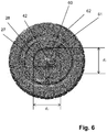
- Fig. 6 illustrates a top view of the valve element and the orientation of the first and second diameters on the valve element.
- a ratio between the first and second diameters d 1 , d 2 of the sleeve 60 is smaller than a ratio of the first and second diameters of the ring-shaped member 37.
- the ring-shaped member 37 can be elliptically shaped having a larger first diameter than the second diameter, while the sleeve 60 is circularly shaped, having a first diameter d 1 similar to the second diameter d 2 .
- the ratio of the ring-shaped member 37 is larger than 1, for example 1.1, while the ratio of the sleeve 60 is 1.
- the sleeve 60 can also be elliptically shaped having a smaller first diameter d 1 than the second diameter d 2 , while the ring-shaped member 37 is circularly shaped.
- the ratio of the sleeve is smaller than 1, for example 0.9, while the ratio of the ring-shaped portion 37 is 1.
- Another design option is to have both the ring-shaped member 37 and the sleeve 60 elliptically shaped on the condition that the ratio of the sleeve 60 is smaller than the ratio of the ring-shaped member 37.
- the ratio of the ring-shaped member 37 is for example 1.1
- the ratio of the sleeve is for example 1.05.
- the difference in ratios between the ring-shaped member 37 and the sleeve 60 is such that, when, during assembly of the valve element 26 and the basic assembly 9, the sleeve 60 encloses or is enclosed by the ring-shaped member 37 and is stretched or widened along the first diameter d 1 , and compressed or narrowed along the second diameter d 2 .
- the slit 42 is consequently stretched in the direction of the first diameter d 1 and contracted in the direction of the second diameter d 2 .
- the slit 42 stretched in the direction of the first diameter d 1 increases the threshold at which slit 42 opens and thus increases the leak resistance of the valve cover device 5.
- the ring-shaped member 37 having a larger first diameter than the second diameter, while the sleeve 60 is circularly shaped is preferred because the tangential orientation of the valve element 26 with repect to the basic assembly 9 is not relevant: the slit 42 will be prestressed at any orientation with respect to the ring-shaped member 37. This arrangement is beneficial to a user as he does not have to check upon assembly how to orient the valve element 26 with respect to the basic assembly 9.
- the valve element 26 is provided with a valve 61 for allowing air to pass from one side of the element to the other.
- the valve 61 comprises a duckbill, for example.
- the valve 61 for allowing air to pass is arranged in the outer ring-shaped portion 28.
- the valve element 26 can also be provided with at least one, but preferably more than one, air channel 62.
- the air channels 62 for allowing air to pass are arranged on the edge of the valve element 26.
- the air channels 62 are suitable for air to pass, but are too small for liquid to flow from an interior of the drinking container 11 to outside of the interior of the drinking container 11.
- the valve element 26 can be provided with one or more air valves 61, with one or more air channels 61 or with a combination of both.
- Fig. 2 illustrates how the valve element 26 is positioned with respect to the spout 31, and shows that the dome-shaped central portion 27 of the valve element 26 is present inside the spout 31 at the base of the spout 31.
- a sleeve 60 surrounds the central portion 27 of the valve element 26.
- the sleeve 60 is positioned around the ring-shaped member 37.
- the valve element 26 is held in its position and is prevented from moving by the sleeve 60 and the tight space between the drink container 11 and the cover device 5.
- the valve element 26 may be retained inside the cover device 5 in any suitable manner, for example through a connection to the housing 30 at a position close to its outer periphery, or by means of a separate retainer.
- the air valve 61 opens so that the underpressure can be normalized due to an aeration effect.
- the underpressure can also be normalised by the air channels 62.
- the slit 42 In a rest position of the valve element 26 in the cover device 5, the slit 42 is closed. In a situation of overpressure at the container side of the valve element 26, the slit 42 is closed as well, wherein an extra tight closure is realized under the influence of tensions prevailing in the valve element 26. In particular, in such a situation, a pressure difference is prevailing across the entire valve element 26, i.e. across both the central portion 27 and the outer ring-shaped portion 28. Under the influence of this pressure difference, the outer ring-shaped portion 28 is deformed to a considerable extent.
- the base of the spout 31 projects inside the housing 30 along a certain distance, and the outer ring-shaped portion 28 is pressed in a direction towards the basic assembly 9, thereby moving in a space which is present between the outer ring-shaped portion 28 and the housing 30 due to the projecting arrangement of the spout 31.
- the outer ring-shaped portion 28 may be provided with a corrugated portion 43 as is the case in the shown example, for locally weakening the outer ring-shaped portion 28 and guaranteeing a tilting movement of a portion 44 of the outer ring-shaped portion 28 as present between the corrugated portion 43 and the contact between the base of the spout 31 and the valve element 26.
- the tilting movement is continued in the central portion 27 of the valve element 26, wherein portions delimiting the slit 42 are tilted and deformed, as a result of which the central portion 27 is flattened similarly to the flattened central portion 27 of the third embodiment as illustrated in Fig. 12.
- the slit 42 is firmly closed, and a sealing function of the valve arrangement 20 as desired in the situation of overpressure is realized.
- the valve element 26 includes a number of strengthening ribs 45,46,47 as is the case in the shown example, so that the lever action of the outer ring-shaped portion 28 on the central portion 27 and consequently the closing of the slit 42 may be guaranteed despite of the flexibility of the valve element 26.
- the number of strengthening ribs 45,46,47 may vary dependent on for example the thickness of the valve element 26, the length in radial length and the width in tangential direction of the strenthening ribs.
- the strengthening ribs 45,46,47 to support the lever action are located on the bottle side of the valve element 26 and on central portion 27. It is the objective of the strengthening ribs 45,46 to support the lever action of the secondary portion 28 on the primary portion 27 which is supposed to take place when overpressure is prevailing in a drink container 11 as covered by the cover device 5.
- the strengthening ribs 47 on the central portion 27 of the valve element 26 support the slit 42 in closing upon underpressure in the drink container 11.
- One of the strengthening ribs 46 may be an elongated strengthening rib 46, such that the rib 46 extends further from the valve element 26.
- the elongated strengthening rib 46 functions as a handle. The handle 46 enables a user to easily remove the valve element 26 from the cover device 5. The user can then easily clean the valve element 26 and the cover device 5.
- Cover device 5 for a drink container 11 comprises a basic assembly 9 which is provided with at least one drink opening 32 and a ring-shaped portion 37.
- the basic assembly 9 may comprise a housing 30 and a spout 31 which projects from the housing 30 and which has the drink opening 32 at a free end thereof.
- the cover device 5 further comprises a valve arrangement 20 which is adapted to assume a closed state for blocking a passage to the drink opening 32 in the basic assembly 9 from a side of the cover device 5 which is intended to face the drink container 11, and to assume an opened state for unblocking the passage as mentioned.
- the valve arrangement 20 comprises a valve element 26 comprising a sleeve 60 and a slit 42, a circumference of the sleeve 60 being substantially similar to a circumference of the ring-shaped member 37.
- the leak resistance of the valve arrangement is further improved in that the sleeve 60 and the ring-shaped member 37 have a first diameter in the direction of the slit 42 and a second diameter perpendicular to the slit 42, wherein a ratio between the first and second diameters of the sleeve 60 is smaller than a ratio between the first and second diameters of the ring-shaped member 37.
- the valve arrangement 20 comprises a valve element 26 having portions 27, 28 which are connected to each other through an area of the valve element 26 at a position where the valve element 26 is hingably associated with the basic assembly 9, wherein only one of the portions 27, 28 of the valve element 26 is in direct communication with the drink opening 32 of the basic assembly 9, and wherein sizing, positioning and orientation of the portions 27, 28 of the valve element 26 are realized for having a smaller total moment of force on a portion 27 of the valve element 26 which is in direct communication with the drink opening 32 of the basic assembly 9 than on another portion 28 of the valve element 26 not being in direct communication with the drink opening 32, when the valve element 26 is subjected to pressure from the side of the cover device 5 which is intended to face the drink container 11.
- the cover device 5 Due to the fact the only one of the two portions 27, 28 of the valve element 26 is in direct communication with the drink opening 32 of the basic assembly 9, and the other of the two portions 27, 28 is not, it is possible to have different reactions of the valve element 26 on underpressure prevailing at a side of the valve element 26 which is associated with the drink opening 32, which is realized when a user wants to drink and exerts a suction force through the drink opening 32 for that purpose, and overpressure prevailing at a drink container side of the flexible element 26 even though the pressure differences across the valve element 26 can be comparable for both situations, at least as far as their direction is concerned. Due to this fact, it is possible for the cover device 5 to have a leakproof nature, while the valve arrangement 20 can be very well responsive to a suction action, so that the user is not compelled to exert a high suction force.
- the different reactions of the valve element 26 in the different situations are obtained on the basis of the fact that in the first situation, only the portion 27 of the valve element 26 which is under the direct influence of the drink opening 32 of the basic assembly 9 is addressed, whereas in the second situation, both portions 27, 28 of the valve element 26 are addressed.
- the design of the valve element 26 and the design of the basic assembly 9 in which the valve element 26 is accommodated are chosen such that in the second situation, the portion 27 of the valve element 26 which is under the direct influence of the drink opening 32 is exerted to a lever action by the other portion 28 wherein the lever action is stronger than the inclination of the first portion 27 to respond to a pressure difference in the same way as in the first situation.
- this effect may be achieved by letting the one portion 27 be smaller than the other portion 28, provided that distances of the one portion 27 to a hinge area are not very much larger than distances of the other portion 28 to the hinge area.
- sizing, positioning and orientation of the portions 27, 28 of the valve element 26 are realized for having a smaller total moment of force on a portion 27 of the valve element 26 which is in direct communication with the drink opening 32 of the basic assembly 9 than on another portion 28 of the valve element 26 not being in direct communication with the drink opening 32, when the valve element 26is subjected to pressure from the side of the cover device 5 which is intended to face the drink container 11.
- the values thereof may be determined by a design factor such as the position on the valve element 26 of the hinge association with the surface portion of the basic assembly 9.
- the hinge association of the valve element 26 with the supporting surface portion of the basic assembly 9 is a hinge contact. That does not alter the fact that within the framework of the present invention, it is also possible for the hinge association to be a hinge connection.
- the valve element 26 may be connected to the ring-shaped member 37 instead of only contacting the ring-shaped member 37, wherein the connection is at a side of the valve element 26, at a position where the hinging effect takes place.
- a ring-shaped member can be provided as a standing part of a membrane, wherein the connection is at a top edge of the ring-shaped member. The hinging effect does not necessarily need to be present at the position of the connection.
- connection may be located at the top edge of the ring-shaped member, whereas a hinge may be present at a position at a bottom edge of the ring-shaped member, i.e. a position where the ring-shaped member is attached to the membrane, wherein the hinge may be realized by letting the ring-shaped member at the bottom side be sufficiently thin, to mention one possibility.
- valve element 26 which is arranged for assuming different positions/appearances with respect to the basic assembly 9 and thereby controlling an extent to which a passage to the drink opening 32 of the basic assembly 9 is blocked, wherein two portions 27, 28 can be distinguished on the valve element 26 which are separated by association to another element, which may be a separate element or an integral element, as explained in the foregoing, which has a function in suspending/supporting the valve element 26 from/on a supporting surface portion of the basic assembly 9, wherein the association is such that hinging movements of the element 26 are allowed to take place under the influence of the various possible pressures acting on the element 26.
- overpressure and "underpressure” as used in this text are understood such as to imply a higher pressure than ambient pressure and a lower pressure than ambient pressure, respectively.
- the basic assembly 9 does not necessarily need to be equipped with a spout 31, as long as it is possible for a user of the cover device 5 to drink from the drink opening 32 by exerting a suction force. It is practical for the drink opening 32 to be present at an end of an element projecting from a housing 30, as is the case with a spout 31, but this is not essential within the framework of the present invention.
Landscapes
- Engineering & Computer Science (AREA)
- Mechanical Engineering (AREA)
- Health & Medical Sciences (AREA)
- General Health & Medical Sciences (AREA)
- Pediatric Medicine (AREA)
- Closures For Containers (AREA)
- Table Devices Or Equipment (AREA)
Claims (4)
- Abdeckvorrichtung (5) für einen Trinkbehälter (11), wobei die Abdeckvorrichtung umfasst:eine Grundbaugruppe (9), die eine Trinköffnung (32) und eine ringförmige Komponente (37) besitzt;eine Ventilanordnung (20), die ein Ventilelement (26) umfasst, das einen zentralen Abschnitt (27) und einen äußeren ringförmigen Abschnitt (28) besitzt, die durch einen Bereich des Ventilelements (26) an einer Stelle miteinander verbunden sind, an der das Ventilelement (26) durch Berührung mit der ringförmigen Komponente (37) gelenkig mit der Grundbaugruppe (9) gekoppelt ist, wobei sich nur der zentrale Abschnitt (27) des Ventilelements (26) in direkter Kommunikation mit der Trinköffnung (32) der Grundbaugruppe (9) befindet, und wobei Dimensionierung, Positionierung und Ausrichtung der Abschnitte (27, 28) des Ventilelements (26) dafür ausgeführt sind, ein kleineres Gesamtkraftmoment an dem zentralen Abschnitt (27) des Ventilelements (26) zu besitzen als an dem äußeren ringförmigen Abschnitt (28) des Ventilelements (26), wenn das Ventilelement (26) von der Seite der Trinkvorrichtung (5), die dazu vorgesehen ist, dem Trinkbehälter (11) zugewandt zu sein, mit Druck beaufschlagt wird,wobei das Ventilelement (26) eine Hülse (60) umfasst, wobei ein Umfang der Hülse (60) einem Umfang der ringförmigen Komponente (37) weitgehend ähnlich ist; wobei sich innerhalb der Hülse (60) in dem zentralen Abschnitt (27) des Ventilelements (26) ein Schlitz (42) befindet, wobei die Hülse (60) und die ringförmige Komponente (37) einen ersten Durchmesser in der Richtung des Schlitzes und einen zweiten Durchmesser senkrecht zu dem Schlitz besitzen, und wobei ein Verhältnis zwischen dem ersten und zweiten Durchmesser der Hülse (60) vor Zusammenbau der Hülse (60) und der ringförmigen Komponente (37) kleiner ist als ein Verhältnis zwischen dem ersten und zweiten Durchmesser der ringförmigen Komponente (37), derart, dass während des Zusammenbaus des Ventilelements (26) und der Grundbaugruppe (9) die Hülse (60) die ringförmige Komponente (37) umschließt oder von dieser umschlossen wird und entlang des ersten Durchmessers gedehnt oder geweitet, und entlang des zweiten Durchmessers zusammengedrückt oder eingeengt wird.
- Abdeckvorrichtung nach Anspruch 1, wobei die ringförmige Komponente (37) kreisförmig ist, während der erste Durchmesser der Hülse (60) kleiner ist als der zweite Durchmesser der Hülse (60).
- Abdeckvorrichtung nach Anspruch 1, wobei die Hülse (60) kreisförmig ist, während der erste Durchmesser der ringförmigen Komponente (37) den zweiten Durchmesser der ringförmigen Komponente (37) übersteigt.
- Baugruppe (10) aus einem Trinkbehälter (11) und einer Abdeckvorrichtung (5) nach einem der vorhergehenden Ansprüche, wobei die Abdeckvorrichtung (5) abnehmbar an dem Trinkbehälter (11) befestigt ist.
Applications Claiming Priority (2)
| Application Number | Priority Date | Filing Date | Title |
|---|---|---|---|
| EP14172197 | 2014-06-12 | ||
| PCT/EP2015/062296 WO2015189074A1 (en) | 2014-06-12 | 2015-06-02 | Cover device for a drink container |
Publications (2)
| Publication Number | Publication Date |
|---|---|
| EP3154869A1 EP3154869A1 (de) | 2017-04-19 |
| EP3154869B1 true EP3154869B1 (de) | 2017-11-01 |
Family
ID=50943138
Family Applications (1)
| Application Number | Title | Priority Date | Filing Date |
|---|---|---|---|
| EP15725067.1A Active EP3154869B1 (de) | 2014-06-12 | 2015-06-02 | Abdeckvorrichtung für einen trinkbehälter |
Country Status (7)
| Country | Link |
|---|---|
| US (1) | US10349766B2 (de) |
| EP (1) | EP3154869B1 (de) |
| JP (1) | JP6349416B2 (de) |
| CN (1) | CN106458390B (de) |
| BR (1) | BR112016028751A2 (de) |
| RU (1) | RU2666214C2 (de) |
| WO (1) | WO2015189074A1 (de) |
Families Citing this family (5)
| Publication number | Priority date | Publication date | Assignee | Title |
|---|---|---|---|---|
| US9795242B2 (en) | 2013-02-14 | 2017-10-24 | Cirkul, Inc. | Additive delivery systems and containers |
| ES2748334T3 (es) | 2014-11-21 | 2020-03-16 | Cirkul Inc | Sistemas de cartuchos de aditivos ajustables |
| US10888826B2 (en) | 2014-11-21 | 2021-01-12 | Cirkul, Inc. | Adjustable additive cartridge systems and methods |
| JP2021534046A (ja) * | 2018-08-08 | 2021-12-09 | モドル アウトドアーズ, エルエルシー | モジュール式ユーティリティボトル |
| EP3843595A4 (de) * | 2018-08-27 | 2022-08-24 | Cirkul, Inc. | Verstellbare additivabgabesysteme und ausgabeverschlussventile dafür |
Family Cites Families (23)
| Publication number | Priority date | Publication date | Assignee | Title |
|---|---|---|---|---|
| US3941149A (en) * | 1974-11-11 | 1976-03-02 | Baxter Laboratories, Inc. | Valve |
| US4660747A (en) * | 1983-06-06 | 1987-04-28 | Aco Lakemedel Ab | Valve element |
| US4711365A (en) * | 1987-02-09 | 1987-12-08 | Fomby Kenneth A | Container and closure assembly with folding sealing ribs |
| JPH0211058U (de) * | 1988-07-07 | 1990-01-24 | ||
| GB2266045B (en) * | 1992-04-07 | 1996-09-18 | Mandy Nicola Haberman | Drinking vessel suitable for use as a trainer cup or the like |
| JPH0676082U (ja) * | 1993-04-13 | 1994-10-25 | 天龍化学工業株式会社 | ねじ蓋付き合成樹脂製キャップ |
| JP2589213Y2 (ja) * | 1993-06-16 | 1999-01-27 | 株式会社吉野工業所 | ノズル兼用中栓付き容器 |
| US5531363A (en) * | 1994-06-10 | 1996-07-02 | Aptargroup, Inc. | Dispensing closure cartridge valve system |
| US5890621A (en) * | 1996-10-21 | 1999-04-06 | Gerber Products Company | Cup for young children with cap valved for fluid control |
| US5706973A (en) * | 1997-01-30 | 1998-01-13 | E. S. Robbins Corporation | Drinking cup and cover with flow control elements |
| US6092551A (en) * | 1998-05-19 | 2000-07-25 | Chesebrough-Pond's Usa Co., Division Of Conopco, Inc. | Duckbill valve |
| US6357620B1 (en) * | 1997-08-21 | 2002-03-19 | Nouri E. Hakim | No-spill drinking cup apparatus |
| US20050072788A1 (en) * | 1998-02-06 | 2005-04-07 | Playtex Products, Inc. | Flow control element for use with leak-proof cup assemblies |
| AU7254600A (en) * | 1999-12-30 | 2001-07-26 | Johnson & Johnson Consumer Companies, Inc. | Improved elastomeric valve for spill-proof feeding devices |
| JP2005231700A (ja) * | 2004-02-23 | 2005-09-02 | Shirouma Science Co Ltd | 吐出バルブ装置 |
| US20070138121A1 (en) * | 2005-11-16 | 2007-06-21 | The Last Straw, Llc | Drinking devices for children with integrated valve |
| US7556172B2 (en) * | 2006-11-30 | 2009-07-07 | Thermos, L.L.C. | Spill resistant lid assembly for a drink container |
| DE202007006080U1 (de) * | 2007-04-27 | 2007-08-02 | Mapa Gmbh Gummi- Und Plastikwerke | Verschlußsystem für eine Kindertrinkflasche oder einen Kindertrinkbecher |
| WO2010018755A1 (ja) | 2008-08-11 | 2010-02-18 | 株式会社日立製作所 | トランスポート制御サーバ、ネットワークシステム及びトランスポート制御方法 |
| US8333299B2 (en) * | 2009-05-22 | 2012-12-18 | Handi-Craft Company | Leak resistant drinking cup |
| US20130026196A1 (en) * | 2011-07-25 | 2013-01-31 | Jan Essebaggers | Self closing flow control device with adjustable actuator element for container closures |
| GB2484013B (en) * | 2011-10-05 | 2012-09-05 | Chawarin Sakulsacha | Container |
| JP5938289B2 (ja) * | 2012-07-26 | 2016-06-22 | キッコーマン株式会社 | 吐出容器 |
-
2015
- 2015-06-02 US US15/316,969 patent/US10349766B2/en active Active
- 2015-06-02 WO PCT/EP2015/062296 patent/WO2015189074A1/en active Application Filing
- 2015-06-02 JP JP2016572553A patent/JP6349416B2/ja not_active Expired - Fee Related
- 2015-06-02 BR BR112016028751A patent/BR112016028751A2/pt not_active Application Discontinuation
- 2015-06-02 EP EP15725067.1A patent/EP3154869B1/de active Active
- 2015-06-02 CN CN201580031162.4A patent/CN106458390B/zh active Active
- 2015-06-02 RU RU2017100258A patent/RU2666214C2/ru active
Non-Patent Citations (1)
| Title |
|---|
| None * |
Also Published As
| Publication number | Publication date |
|---|---|
| RU2017100258A (ru) | 2018-07-16 |
| US10349766B2 (en) | 2019-07-16 |
| RU2666214C2 (ru) | 2018-09-06 |
| US20170112309A1 (en) | 2017-04-27 |
| JP2017523092A (ja) | 2017-08-17 |
| WO2015189074A1 (en) | 2015-12-17 |
| CN106458390B (zh) | 2018-12-07 |
| RU2017100258A3 (de) | 2018-07-16 |
| EP3154869A1 (de) | 2017-04-19 |
| BR112016028751A2 (pt) | 2017-08-22 |
| JP6349416B2 (ja) | 2018-06-27 |
| CN106458390A (zh) | 2017-02-22 |
Similar Documents
| Publication | Publication Date | Title |
|---|---|---|
| US10080452B2 (en) | Cover device for a drink container | |
| EP3154869B1 (de) | Abdeckvorrichtung für einen trinkbehälter | |
| JP4740227B2 (ja) | 流動物を保持する容器の閉塞体 | |
| US7070065B2 (en) | Closure assembly for drinking vessel | |
| CN107720675B (zh) | 具有减压阀的容器 | |
| US20050133519A1 (en) | Straw drinking cup | |
| US20050205587A1 (en) | Cup assembly | |
| US9834345B2 (en) | Closure for a bottle | |
| KR101485171B1 (ko) | 빨대삽입밸브를 구비하는 빨대컵 | |
| US20050006415A1 (en) | Two-part closure system and nozzle with groove | |
| EP3154401B1 (de) | Abdeckvorrichtung für einen trinkbehälter | |
| US20040144435A1 (en) | Check valve | |
| JP2016104642A (ja) | エアーバックレスキャップ、およびこのキャップを備えた容器 | |
| JP7453031B2 (ja) | 複合蓋 | |
| KR200189559Y1 (ko) | 우유병 마개 | |
| WO2012099669A1 (en) | Cap and spout assembly |
Legal Events
| Date | Code | Title | Description |
|---|---|---|---|
| STAA | Information on the status of an ep patent application or granted ep patent |
Free format text: STATUS: THE INTERNATIONAL PUBLICATION HAS BEEN MADE |
|
| PUAI | Public reference made under article 153(3) epc to a published international application that has entered the european phase |
Free format text: ORIGINAL CODE: 0009012 |
|
| STAA | Information on the status of an ep patent application or granted ep patent |
Free format text: STATUS: REQUEST FOR EXAMINATION WAS MADE |
|
| 17P | Request for examination filed |
Effective date: 20170112 |
|
| AK | Designated contracting states |
Kind code of ref document: A1 Designated state(s): AL AT BE BG CH CY CZ DE DK EE ES FI FR GB GR HR HU IE IS IT LI LT LU LV MC MK MT NL NO PL PT RO RS SE SI SK SM TR |
|
| AX | Request for extension of the european patent |
Extension state: BA ME |
|
| GRAP | Despatch of communication of intention to grant a patent |
Free format text: ORIGINAL CODE: EPIDOSNIGR1 |
|
| STAA | Information on the status of an ep patent application or granted ep patent |
Free format text: STATUS: GRANT OF PATENT IS INTENDED |
|
| INTG | Intention to grant announced |
Effective date: 20170522 |
|
| DAV | Request for validation of the european patent (deleted) | ||
| DAX | Request for extension of the european patent (deleted) | ||
| GRAS | Grant fee paid |
Free format text: ORIGINAL CODE: EPIDOSNIGR3 |
|
| GRAA | (expected) grant |
Free format text: ORIGINAL CODE: 0009210 |
|
| STAA | Information on the status of an ep patent application or granted ep patent |
Free format text: STATUS: THE PATENT HAS BEEN GRANTED |
|
| AK | Designated contracting states |
Kind code of ref document: B1 Designated state(s): AL AT BE BG CH CY CZ DE DK EE ES FI FR GB GR HR HU IE IS IT LI LT LU LV MC MK MT NL NO PL PT RO RS SE SI SK SM TR |
|
| REG | Reference to a national code |
Ref country code: GB Ref legal event code: FG4D |
|
| REG | Reference to a national code |
Ref country code: CH Ref legal event code: EP Ref country code: AT Ref legal event code: REF Ref document number: 941778 Country of ref document: AT Kind code of ref document: T Effective date: 20171115 |
|
| REG | Reference to a national code |
Ref country code: IE Ref legal event code: FG4D |
|
| REG | Reference to a national code |
Ref country code: DE Ref legal event code: R096 Ref document number: 602015005744 Country of ref document: DE |
|
| REG | Reference to a national code |
Ref country code: NL Ref legal event code: MP Effective date: 20171101 |
|
| REG | Reference to a national code |
Ref country code: LT Ref legal event code: MG4D |
|
| REG | Reference to a national code |
Ref country code: AT Ref legal event code: MK05 Ref document number: 941778 Country of ref document: AT Kind code of ref document: T Effective date: 20171101 |
|
| PG25 | Lapsed in a contracting state [announced via postgrant information from national office to epo] |
Ref country code: SE Free format text: LAPSE BECAUSE OF FAILURE TO SUBMIT A TRANSLATION OF THE DESCRIPTION OR TO PAY THE FEE WITHIN THE PRESCRIBED TIME-LIMIT Effective date: 20171101 Ref country code: NL Free format text: LAPSE BECAUSE OF FAILURE TO SUBMIT A TRANSLATION OF THE DESCRIPTION OR TO PAY THE FEE WITHIN THE PRESCRIBED TIME-LIMIT Effective date: 20171101 Ref country code: ES Free format text: LAPSE BECAUSE OF FAILURE TO SUBMIT A TRANSLATION OF THE DESCRIPTION OR TO PAY THE FEE WITHIN THE PRESCRIBED TIME-LIMIT Effective date: 20171101 Ref country code: LT Free format text: LAPSE BECAUSE OF FAILURE TO SUBMIT A TRANSLATION OF THE DESCRIPTION OR TO PAY THE FEE WITHIN THE PRESCRIBED TIME-LIMIT Effective date: 20171101 Ref country code: NO Free format text: LAPSE BECAUSE OF FAILURE TO SUBMIT A TRANSLATION OF THE DESCRIPTION OR TO PAY THE FEE WITHIN THE PRESCRIBED TIME-LIMIT Effective date: 20180201 Ref country code: FI Free format text: LAPSE BECAUSE OF FAILURE TO SUBMIT A TRANSLATION OF THE DESCRIPTION OR TO PAY THE FEE WITHIN THE PRESCRIBED TIME-LIMIT Effective date: 20171101 |
|
| PG25 | Lapsed in a contracting state [announced via postgrant information from national office to epo] |
Ref country code: AT Free format text: LAPSE BECAUSE OF FAILURE TO SUBMIT A TRANSLATION OF THE DESCRIPTION OR TO PAY THE FEE WITHIN THE PRESCRIBED TIME-LIMIT Effective date: 20171101 Ref country code: RS Free format text: LAPSE BECAUSE OF FAILURE TO SUBMIT A TRANSLATION OF THE DESCRIPTION OR TO PAY THE FEE WITHIN THE PRESCRIBED TIME-LIMIT Effective date: 20171101 Ref country code: HR Free format text: LAPSE BECAUSE OF FAILURE TO SUBMIT A TRANSLATION OF THE DESCRIPTION OR TO PAY THE FEE WITHIN THE PRESCRIBED TIME-LIMIT Effective date: 20171101 Ref country code: GR Free format text: LAPSE BECAUSE OF FAILURE TO SUBMIT A TRANSLATION OF THE DESCRIPTION OR TO PAY THE FEE WITHIN THE PRESCRIBED TIME-LIMIT Effective date: 20180202 Ref country code: IS Free format text: LAPSE BECAUSE OF FAILURE TO SUBMIT A TRANSLATION OF THE DESCRIPTION OR TO PAY THE FEE WITHIN THE PRESCRIBED TIME-LIMIT Effective date: 20180301 Ref country code: BG Free format text: LAPSE BECAUSE OF FAILURE TO SUBMIT A TRANSLATION OF THE DESCRIPTION OR TO PAY THE FEE WITHIN THE PRESCRIBED TIME-LIMIT Effective date: 20180201 Ref country code: LV Free format text: LAPSE BECAUSE OF FAILURE TO SUBMIT A TRANSLATION OF THE DESCRIPTION OR TO PAY THE FEE WITHIN THE PRESCRIBED TIME-LIMIT Effective date: 20171101 |
|
| REG | Reference to a national code |
Ref country code: FR Ref legal event code: PLFP Year of fee payment: 4 |
|
| PG25 | Lapsed in a contracting state [announced via postgrant information from national office to epo] |
Ref country code: EE Free format text: LAPSE BECAUSE OF FAILURE TO SUBMIT A TRANSLATION OF THE DESCRIPTION OR TO PAY THE FEE WITHIN THE PRESCRIBED TIME-LIMIT Effective date: 20171101 Ref country code: DK Free format text: LAPSE BECAUSE OF FAILURE TO SUBMIT A TRANSLATION OF THE DESCRIPTION OR TO PAY THE FEE WITHIN THE PRESCRIBED TIME-LIMIT Effective date: 20171101 Ref country code: SK Free format text: LAPSE BECAUSE OF FAILURE TO SUBMIT A TRANSLATION OF THE DESCRIPTION OR TO PAY THE FEE WITHIN THE PRESCRIBED TIME-LIMIT Effective date: 20171101 Ref country code: CY Free format text: LAPSE BECAUSE OF FAILURE TO SUBMIT A TRANSLATION OF THE DESCRIPTION OR TO PAY THE FEE WITHIN THE PRESCRIBED TIME-LIMIT Effective date: 20171101 Ref country code: CZ Free format text: LAPSE BECAUSE OF FAILURE TO SUBMIT A TRANSLATION OF THE DESCRIPTION OR TO PAY THE FEE WITHIN THE PRESCRIBED TIME-LIMIT Effective date: 20171101 |
|
| REG | Reference to a national code |
Ref country code: DE Ref legal event code: R097 Ref document number: 602015005744 Country of ref document: DE |
|
| PG25 | Lapsed in a contracting state [announced via postgrant information from national office to epo] |
Ref country code: PL Free format text: LAPSE BECAUSE OF FAILURE TO SUBMIT A TRANSLATION OF THE DESCRIPTION OR TO PAY THE FEE WITHIN THE PRESCRIBED TIME-LIMIT Effective date: 20171101 Ref country code: SM Free format text: LAPSE BECAUSE OF FAILURE TO SUBMIT A TRANSLATION OF THE DESCRIPTION OR TO PAY THE FEE WITHIN THE PRESCRIBED TIME-LIMIT Effective date: 20171101 Ref country code: IT Free format text: LAPSE BECAUSE OF FAILURE TO SUBMIT A TRANSLATION OF THE DESCRIPTION OR TO PAY THE FEE WITHIN THE PRESCRIBED TIME-LIMIT Effective date: 20171101 Ref country code: RO Free format text: LAPSE BECAUSE OF FAILURE TO SUBMIT A TRANSLATION OF THE DESCRIPTION OR TO PAY THE FEE WITHIN THE PRESCRIBED TIME-LIMIT Effective date: 20171101 |
|
| PLBE | No opposition filed within time limit |
Free format text: ORIGINAL CODE: 0009261 |
|
| STAA | Information on the status of an ep patent application or granted ep patent |
Free format text: STATUS: NO OPPOSITION FILED WITHIN TIME LIMIT |
|
| 26N | No opposition filed |
Effective date: 20180802 |
|
| REG | Reference to a national code |
Ref country code: CH Ref legal event code: PL |
|
| REG | Reference to a national code |
Ref country code: BE Ref legal event code: MM Effective date: 20180630 |
|
| REG | Reference to a national code |
Ref country code: IE Ref legal event code: MM4A |
|
| PG25 | Lapsed in a contracting state [announced via postgrant information from national office to epo] |
Ref country code: MC Free format text: LAPSE BECAUSE OF FAILURE TO SUBMIT A TRANSLATION OF THE DESCRIPTION OR TO PAY THE FEE WITHIN THE PRESCRIBED TIME-LIMIT Effective date: 20171101 Ref country code: LU Free format text: LAPSE BECAUSE OF NON-PAYMENT OF DUE FEES Effective date: 20180602 |
|
| PG25 | Lapsed in a contracting state [announced via postgrant information from national office to epo] |
Ref country code: LI Free format text: LAPSE BECAUSE OF NON-PAYMENT OF DUE FEES Effective date: 20180630 Ref country code: IE Free format text: LAPSE BECAUSE OF NON-PAYMENT OF DUE FEES Effective date: 20180602 Ref country code: CH Free format text: LAPSE BECAUSE OF NON-PAYMENT OF DUE FEES Effective date: 20180630 |
|
| PG25 | Lapsed in a contracting state [announced via postgrant information from national office to epo] |
Ref country code: BE Free format text: LAPSE BECAUSE OF NON-PAYMENT OF DUE FEES Effective date: 20180630 |
|
| PGFP | Annual fee paid to national office [announced via postgrant information from national office to epo] |
Ref country code: FR Payment date: 20190625 Year of fee payment: 5 |
|
| PGFP | Annual fee paid to national office [announced via postgrant information from national office to epo] |
Ref country code: GB Payment date: 20190627 Year of fee payment: 5 |
|
| PG25 | Lapsed in a contracting state [announced via postgrant information from national office to epo] |
Ref country code: MT Free format text: LAPSE BECAUSE OF NON-PAYMENT OF DUE FEES Effective date: 20180602 |
|
| PG25 | Lapsed in a contracting state [announced via postgrant information from national office to epo] |
Ref country code: PT Free format text: LAPSE BECAUSE OF FAILURE TO SUBMIT A TRANSLATION OF THE DESCRIPTION OR TO PAY THE FEE WITHIN THE PRESCRIBED TIME-LIMIT Effective date: 20171101 |
|
| PG25 | Lapsed in a contracting state [announced via postgrant information from national office to epo] |
Ref country code: HU Free format text: LAPSE BECAUSE OF FAILURE TO SUBMIT A TRANSLATION OF THE DESCRIPTION OR TO PAY THE FEE WITHIN THE PRESCRIBED TIME-LIMIT; INVALID AB INITIO Effective date: 20150602 Ref country code: MK Free format text: LAPSE BECAUSE OF NON-PAYMENT OF DUE FEES Effective date: 20171101 |
|
| PG25 | Lapsed in a contracting state [announced via postgrant information from national office to epo] |
Ref country code: AL Free format text: LAPSE BECAUSE OF FAILURE TO SUBMIT A TRANSLATION OF THE DESCRIPTION OR TO PAY THE FEE WITHIN THE PRESCRIBED TIME-LIMIT Effective date: 20171101 |
|
| PGFP | Annual fee paid to national office [announced via postgrant information from national office to epo] |
Ref country code: TR Payment date: 20200527 Year of fee payment: 6 |
|
| PG25 | Lapsed in a contracting state [announced via postgrant information from national office to epo] |
Ref country code: SI Free format text: LAPSE BECAUSE OF NON-PAYMENT OF DUE FEES Effective date: 20180602 |
|
| GBPC | Gb: european patent ceased through non-payment of renewal fee |
Effective date: 20200602 |
|
| PG25 | Lapsed in a contracting state [announced via postgrant information from national office to epo] |
Ref country code: GB Free format text: LAPSE BECAUSE OF NON-PAYMENT OF DUE FEES Effective date: 20200602 Ref country code: FR Free format text: LAPSE BECAUSE OF NON-PAYMENT OF DUE FEES Effective date: 20200630 |
|
| PGFP | Annual fee paid to national office [announced via postgrant information from national office to epo] |
Ref country code: DE Payment date: 20230627 Year of fee payment: 9 |