EP3153720B1 - Tablarverbinder mit aufspreizbarem einbohrtopf - Google Patents
Tablarverbinder mit aufspreizbarem einbohrtopf Download PDFInfo
- Publication number
- EP3153720B1 EP3153720B1 EP16174920.5A EP16174920A EP3153720B1 EP 3153720 B1 EP3153720 B1 EP 3153720B1 EP 16174920 A EP16174920 A EP 16174920A EP 3153720 B1 EP3153720 B1 EP 3153720B1
- Authority
- EP
- European Patent Office
- Prior art keywords
- pot
- drilling
- support part
- bore
- component
- Prior art date
- Legal status (The legal status is an assumption and is not a legal conclusion. Google has not performed a legal analysis and makes no representation as to the accuracy of the status listed.)
- Not-in-force
Links
- 230000037431 insertion Effects 0.000 claims description 13
- 238000003780 insertion Methods 0.000 claims description 13
- 239000002023 wood Substances 0.000 claims description 5
- 229920002522 Wood fibre Polymers 0.000 claims description 4
- 239000002025 wood fiber Substances 0.000 claims description 4
- 238000005553 drilling Methods 0.000 claims 15
- 230000002093 peripheral effect Effects 0.000 description 12
- 101100390736 Danio rerio fign gene Proteins 0.000 description 6
- 101100390738 Mus musculus Fign gene Proteins 0.000 description 6
- 238000010079 rubber tapping Methods 0.000 description 5
- 239000000463 material Substances 0.000 description 4
- 238000004873 anchoring Methods 0.000 description 2
- 239000011324 bead Substances 0.000 description 2
- 210000003128 head Anatomy 0.000 description 2
- 210000001331 nose Anatomy 0.000 description 2
- 229920001131 Pulp (paper) Polymers 0.000 description 1
- HCHKCACWOHOZIP-UHFFFAOYSA-N Zinc Chemical compound [Zn] HCHKCACWOHOZIP-UHFFFAOYSA-N 0.000 description 1
- 101150038956 cup-4 gene Proteins 0.000 description 1
- 238000004512 die casting Methods 0.000 description 1
- 238000004806 packaging method and process Methods 0.000 description 1
- 239000011701 zinc Substances 0.000 description 1
- 229910052725 zinc Inorganic materials 0.000 description 1
Images




Classifications
-
- F—MECHANICAL ENGINEERING; LIGHTING; HEATING; WEAPONS; BLASTING
- F16—ENGINEERING ELEMENTS AND UNITS; GENERAL MEASURES FOR PRODUCING AND MAINTAINING EFFECTIVE FUNCTIONING OF MACHINES OR INSTALLATIONS; THERMAL INSULATION IN GENERAL
- F16B—DEVICES FOR FASTENING OR SECURING CONSTRUCTIONAL ELEMENTS OR MACHINE PARTS TOGETHER, e.g. NAILS, BOLTS, CIRCLIPS, CLAMPS, CLIPS OR WEDGES; JOINTS OR JOINTING
- F16B12/00—Jointing of furniture or the like, e.g. hidden from exterior
- F16B12/44—Leg joints; Corner joints
- F16B12/46—Non-metal corner connections
-
- F—MECHANICAL ENGINEERING; LIGHTING; HEATING; WEAPONS; BLASTING
- F16—ENGINEERING ELEMENTS AND UNITS; GENERAL MEASURES FOR PRODUCING AND MAINTAINING EFFECTIVE FUNCTIONING OF MACHINES OR INSTALLATIONS; THERMAL INSULATION IN GENERAL
- F16B—DEVICES FOR FASTENING OR SECURING CONSTRUCTIONAL ELEMENTS OR MACHINE PARTS TOGETHER, e.g. NAILS, BOLTS, CIRCLIPS, CLAMPS, CLIPS OR WEDGES; JOINTS OR JOINTING
- F16B12/00—Jointing of furniture or the like, e.g. hidden from exterior
- F16B12/10—Jointing of furniture or the like, e.g. hidden from exterior using pegs, bolts, tenons, clamps, clips, or the like
- F16B12/12—Jointing of furniture or the like, e.g. hidden from exterior using pegs, bolts, tenons, clamps, clips, or the like for non-metal furniture parts, e.g. made of wood, of plastics
- F16B12/24—Jointing of furniture or the like, e.g. hidden from exterior using pegs, bolts, tenons, clamps, clips, or the like for non-metal furniture parts, e.g. made of wood, of plastics using separate pins, dowels, or the like
-
- F—MECHANICAL ENGINEERING; LIGHTING; HEATING; WEAPONS; BLASTING
- F16—ENGINEERING ELEMENTS AND UNITS; GENERAL MEASURES FOR PRODUCING AND MAINTAINING EFFECTIVE FUNCTIONING OF MACHINES OR INSTALLATIONS; THERMAL INSULATION IN GENERAL
- F16B—DEVICES FOR FASTENING OR SECURING CONSTRUCTIONAL ELEMENTS OR MACHINE PARTS TOGETHER, e.g. NAILS, BOLTS, CIRCLIPS, CLAMPS, CLIPS OR WEDGES; JOINTS OR JOINTING
- F16B12/00—Jointing of furniture or the like, e.g. hidden from exterior
- F16B12/10—Jointing of furniture or the like, e.g. hidden from exterior using pegs, bolts, tenons, clamps, clips, or the like
- F16B12/12—Jointing of furniture or the like, e.g. hidden from exterior using pegs, bolts, tenons, clamps, clips, or the like for non-metal furniture parts, e.g. made of wood, of plastics
- F16B12/26—Jointing of furniture or the like, e.g. hidden from exterior using pegs, bolts, tenons, clamps, clips, or the like for non-metal furniture parts, e.g. made of wood, of plastics using snap-action elements
Definitions
- the invention relates to a connector, in particular tray connector, with a Einbohrtopf for insertion into a lower-side, open-edged bore of a first component and with a support member for fixing in a bore of a second component, wherein the Einbohrtopf an open or closed pot bottom, a pot opening and in his Circumferential wall has a longitudinal slot open to the pot opening, wherein the support part has a support base, an over the support floor upstanding mounting leg and a spreading and wherein the Einbohrtopf with its longitudinal slot and the support member with its mounting leg are plugged into one another.
- Such a connector is for example by the DE 200 02 307 U1 known.
- DE 200 02 307 U1 discloses a three-piece locking fitting with an L-shaped support member, a receiving sleeve and a locking element.
- the support member and the receiving sleeve are inserted into each other, wherein two projecting cams of the support member are engaged behind by locking lugs of the receiving sleeve, so that there is a certain fixation of the receiving sleeve relative to the support member.
- the locking lugs are rounded with a flatter and a steeper edge formed and used for releasable prefixing of the two parts.
- a connector for connecting two wood fiber boards is also by the DE 20 2007 009 771 U1 known.
- the Einbohrtopf in its peripheral wall on two outwardly dividedschwenkbbare detent springs, which have at their upper free ends inwardly projecting beads.
- the locking springs are pivoted by the beads to the outside and thereby pressed into the material of the wood fiber board.
- the tapping pot and the support member are fastened together, and on the other hand, a lateral tightening of Einbohrtopf and support member transversely to the direction of insertion, ie toward each other, causes.
- the locking springs which protrude outwards in the non-installed state, can become entangled with one another, so that the boring heads then have to be carefully separated from one another.
- the Einbohrtopf has on its peripheral wall sections inside two outwardly spreadable detent springs facing each other with their free ends and each directed obliquely in the direction of the pot bottom, wherein the nesting of Einbohrtopf and support member, the detent springs through the Spreizelement be deflected and locked in the Steckendposition behind the spreader.
- the longitudinal slot are tapered in the direction of the bottom of the pot and / or the mounting leg in the direction away from the support base, so that when nesting of Einbohrtopf and support part, the two adjacent to the longitudinal slot peripheral wall portions of the Einbohrtopfs are spread by the mounting leg to the outside.
- the longitudinal slot extends to the bottom of the pot.
- the Einbohrtopf used in the bore of the first component can be aligned by hand at any time by turning.
- the bottom of the pot is closed or open and can be formed in the latter case only by the opening edge of a bottom opening.
- the peripheral wall portions of the boring cup have a ribbing on the outside, e.g. in the form of circumferential ribs on, which press in the spreading of the peripheral wall portions in the bore wall of the first component and thereby anchor the boring pot safely.
- the boring pot at its pot opening at least one radially outwardly projecting edge portion, in particular two or more edge portions have.
- the mounting leg of the support part on a plug-in pin for insertion into the bore of the second component.
- the fastening leg of the carrier part has a through hole for a screw for screwing into the bore of the second component.
- the invention also relates to an arrangement comprising a first component, in particular tray, with a lower-side, open-edged bore, a second component, in particular body wall, with a bore and a connector formed as above, wherein the Einborhrtopf is inserted into the bore of the first component, wherein the support member is fixed with its mounting leg in the bore of the second component and wherein the Einbohrtopf is mounted on the mounting leg of the support member under spreading of the two peripheral wall portions of the Einbohrtopfs and / or latching with the support member.
- the first and / or the second component made of wood or a wood pulp.
- the in Fig. 1 Shelf connector 1 shown serves for attaching a tray 2 ( Fig. 4 ) on a body wall 3 ( Fig. 5 ) and includes a one-piece tapping pot 4 for insertion into a lower-side, open-edged bore 5 of the tray 2 and a one-piece support member 6 for fixing in a bore 7 of the body wall 3.
- the tapping pot 4 made of plastic and the support member 6 made of zinc die-casting.
- the tray 2 and the body wall 3 are, for example, wood fiber boards.
- the boring pot 4 has a pot bottom 8 , a front-side pot opening 9 and in its peripheral wall to a pot opening 9 toward open longitudinal slot 10 which extends to the pot bottom 8 and is tapered towards the pot bottom 8.
- the pot bottom 8 could also be open.
- the two adjacent to the longitudinal slot 10 peripheral wall portions 11 of the Einbohrtopfs 4 have on the outside a ribbing in the form of several axially successively arranged circumferential ribs 12 and on the pot opening 9 two radially outwardly projecting edge portions 13 for depth limitation.
- the circumferential wall sections 11 are on the inside continue two detent springs 14 , which face each other with their free ends and are each directed obliquely in the direction of the pot bottom 8.
- the support member 6 has a support base 15 and a raised above the support base 15 mounting leg 16 .
- the mounting leg 16 on its side facing away from the plug pin 17 has an approximately V-shaped expansion element 19 with two lateral expansion projections 20 on ( Fig. 3 ), which - seen in the direction away from the support floor 15 - each project obliquely away from each other.
- the upper wall section 16a of the fastening leg 16 lying above the plug pin 17 forms an abutment surface which is angled away from the lower wall section 16b below the plug pin 17 by approximately 20 °.
- the boring pot 4 with its longitudinal slot 10 and the support member 6 with its mounting legs 16 are plugged into each other.
- peripheral wall portions 11 of the Einbohrtopfs 4 are spread by the tapered mounting leg 16 to the outside.
- Steckendposition is reached when the edge portions 13 abut the support floor 15.
- FIGS. 4a-4c the assembly of the boring pot 4 in the tray 2 is shown.
- the boring pot 4 is pressed with its aligned to the open edge of the bore 5 longitudinal slot 10 in the bore 5 (diameter 12mm) by hand until the edge portions 13 come to rest on the shelf bottom and thereby limit the Eindschreibiefe.
- the circumferential ribs 12 are not yet in the wall of the bore 5, so pressed into the wood material of the tray 2, so that the boring 4 can be aligned by hand at any time by turning.
- FIGS. 5a-5c the assembly of the support member 6 is shown on the body wall 3.
- the support member 6 is first inserted obliquely with its plug-in pin 17 in the bore 7 (diameter 5mm) of the body wall 3, until the upper wall portion 16a abuts against the body wall 3.
- the support member 6 is tilted by about 20 ° down until the lower wall portion 16b abuts the carcass wall 3 and the support base 15 is aligned horizontally ( Fig. 5c ).
- FIGS. 6a to 6c the attachment of the tray 2 on the body wall 3 by means of the Tablarverbinders 1 is shown.
- the tray 2 is mounted with its boring pot 4 from above on the anchored in the body wall 3 support member 6, wherein the boring pot 4 is inserted with its longitudinal slot 10 on the mounting legs 16 of the support member 6.
- Oblique guide surfaces 22 , 23 on the boring cup 4 and on the mounting leg 16 cause when hanging, that the boring pot 4 is pulled in the direction of the plug pin 17 and thereby rests the tray 2 gap-free on the body wall 3.
- the Einborhrtopf 4 by the locking springs 14 in the support member 6 is locked (clipped).
- Fig. 6c Steckendposition
- FIGS. 9a-9c the assembly of the support member 6 is shown on the body wall 3 by the through-hole 24 by cross-bolt 25 is screwed into the bore 7 of the body wall 3.
Landscapes
- Engineering & Computer Science (AREA)
- General Engineering & Computer Science (AREA)
- Mechanical Engineering (AREA)
- Furniture Connections (AREA)
- Insertion Pins And Rivets (AREA)
- Cultivation Receptacles Or Flower-Pots, Or Pots For Seedlings (AREA)
Description
- Die Erfindung betrifft einen Verbinder, insbesondere Tablarverbinder, mit einem Einbohrtopf zum Einsetzen in eine unterseitige, randoffene Bohrung eines ersten Bauteils und mit einem Trägerteil zum Befestigen in einer Bohrung eines zweiten Bauteils, wobei der Einbohrtopf einen offenen oder geschlossenen Topfboden, eine Topföffnung und in seiner Umfangswand einen bis zur Topföffnung hin offenen Längsschlitz aufweist, wobei das Trägerteil einen Auflageboden, einen über den Auflageboden hochstehenden Befestigungsschenkel und ein Spreizelement aufweist und wobei der Einbohrtopf mit seinem Längsschlitz und das Trägerteil mit seinem Befestigungsschenkel ineinander steckbar sind.
- Ein derartiger Verbinder ist beispielsweise durch das
DE 200 02 307 U1 bekannt geworden. -
DE 200 02 307 U1 offenbart einen dreiteiligen Verriegelungsbeschlag mit einem L-förmigen Tragteil, einer Aufnahmehülse und einem Verriegelungselement. Das Tragteil und die Aufnahmehülse werden ineinandergesteckt, wobei zwei vorspringende Nocken des Trägerteils von Rastnasen der Aufnahmehülse hintergriffen werden, so dass sich eine gewisse Fixierung der Aufnahmehülse gegenüber dem Tragteil ergibt. Die Rastnasen sind abgerundet mit einer flacheren und einer steileren Flanke ausgebildet und dienen zur lösbaren Vorfixierung der beiden Teile. - Ein Verbinder zum Verbinden zweier Holzfaserplatten ist auch durch das
DE 20 2007 009 771 U1 bekannt geworden. Bei diesem bekannten dreiteiligen Verbinder weist der Einbohrtopf in seiner Umfangswand zwei nach außen herausschwenkbbare Rastfedern auf, welche an ihren oberen freien Enden nach innen ragende Wülste besitzen. Beim Einstecken des Trägerteils in den Einbohrtopf werden die Rastfedern durch die Wülste nach außen geschwenkt und dadurch in das Material der Holzfaserplatte gepresst. Durch Verdrehen eines im Trägerteil gelagerten Anzugselements sind einerseits der Einbohrtopf und das Trägerteil aneinander befestigt, und andererseits wird ein seitliches Anziehen von Einbohrtopf und Trägerteil quer zur Steckrichtung, also aufeinander zu, bewirkt. In Verpackungen mit mehreren Einbohrtöpfen können sich die im nichteingebauten Zustand nach außen abstehenden Rastfedern untereinander verhaken, so dass dann die Einbohrtöpfe vorsichtig voneinander getrennt werden müssen. - Es ist die Aufgabe der vorliegenden Erfindung, einen Verbinder der eingangs genannten Art dahingehend weiterzubilden, dass ein Verhaken von Einbohrtöpfen untereinander weitgehend ausgeschlossen und dennoch eine sichere Verankerung des Einbohrtopfs in der Bohrung des ersten Bauteils sichergestellt ist.
- Diese Aufgabe wird erfindungsgemäß dadurch gelöst, dass der Einbohrtopf an seinen Umfangswandabschnitten innenseitig zwei nach außen abspreizbare Rastfedern aufweist, die mit ihren freien Enden einander zugewandt und jeweils schräg in Richtung auf den Topfboden gerichtet sind, wobei beim Ineinanderstecken von Einbohrtopf und Trägerteil die Rastfedern durch das Spreizelement ausgelenkt werden und in der Steckendposition hinter dem Spreizelement verrastet sind.
- Vorzugsweise sind der Längsschlitz in Richtung auf den Topfboden und/oder der Befestigungsschenkel in Richtung fort vom Auflageboden verjüngt, so dass beim Ineinanderstecken von Einbohrtopf und Trägerteil die beiden an den Längsschlitz angrenzenden Umfangswandabschnitte des Einbohrtopfs durch den Befestigungsschenkel nach außen aufgespreizt werden. Vorzugsweise erstreckt sich der Längsschlitz bis zum Topfboden. Beim Ineinanderstecken von Einbohrtopf und Trägerteil werden die Umfangswandabschnitte nach außen aufgespreizt, um sich in die Bohrungswandung des ersten Bauteils einzudrücken und so zu einer stabileren Verankerung des Einbohrtopfes führen. Solange das Trägerteil nicht eingesteckt ist, lässt sich daher der in die Bohrung des ersten Bauteils eingesetzte Einbohrtopf von Hand noch jederzeit durch Verdrehen ausrichten. Der Topfboden ist geschlossen oder offen und kann im letzteren Fall auch nur durch den Öffnungsrand einer Bodenöffnung gebildet sein.
- Besonders bevorzugt weisen die Umfangswandabschnitte des Einbohrtopfs außenseitig eine Verrippung, z.B. in Form von Umfangsrippen, auf, die sich beim Aufspreizen der Umfangswandabschnitte in die Bohrungswandung des ersten Bauteils eindrücken und dadurch den Einbohrtopf sicher verankern.
- Besonders bevorzugt sind am Einbohrtopf und/oder am Befestigungsschenkel schräg zur Steckrichtung verlaufende Führungsflächen vorgesehen, die beim Ineinanderstecken von Einbohrtopf und Trägerteil ein seitliches Anziehen von Einbohrtopf und Trägerteil quer zur Steckrichtung bewirken. Die Schrägflächen übernehmen zusammen mit der Verrastung von Einbohrtopf und Trägerteil die Funktionen des bisher vorhandenen Anzugselements, auf das somit verzichtet werden kann.
- Als Tiefenanschlag kann der Einbohrtopf an seiner Topföffnung mindestens einen radial nach außen vorstehenden Randabschnitt, insbesondere zwei oder mehr Randabschnitte, aufweisen.
- In einer Steckvariante weist der Befestigungsschenkel des Trägerteils einen Steckzapfen zum Einstecken in die Bohrung des zweiten Bauteils auf. In einer Schraubvariante weist der Befestigungsschenkel des Trägerteils ein Durchgangsloch für eine Schraube zum Einschrauben in die Bohrung des zweiten Bauteils auf.
- Die Erfindung betrifft auch eine Anordnung aufweisend ein erstes Bauteil, insbesondere Tablar, mit einer unterseitigen, randoffenen Bohrung, ein zweites Bauteil, insbesondere Korpuswand, mit einer Bohrung und einen wie oben ausgebildeten Verbinder, wobei der Einbohrtopf in die Bohrung des ersten Bauteils eingesetzt ist, wobei das Trägerteil mit seinem Befestigungsschenkel in der Bohrung des zweiten Bauteils befestigt ist und wobei der Einbohrtopf auf den Befestigungsschenkel des Trägerteils unter Aufspreizen der beiden Umfangswandabschnitte des Einbohrtopfs und/oder unter Verrastung mit dem Trägerteil eingehängt ist.
- Vorzugsweise sind das erste und/oder das zweite Bauteil aus Holz oder aus einem Holzfaserstoff gebildet.
- Weitere Vorteile der Erfindung ergeben sich aus der Beschreibung, den Ansprüchen und der Zeichnung. Ebenso können die vorstehend genannten und die noch weiter aufgeführten Merkmale je für sich oder zu mehreren in beliebigen Kombinationen Verwendung finden. Die gezeigten und beschriebenen Ausführungsformen sind nicht als abschließende Aufzählung zu verstehen, sondern haben vielmehr beispielhaften Charakter für die Schilderung der Erfindung.
- Es zeigen:
- Fig. 1
- eine erste Ausführungsform eines erfindungsgemäßen Tablarverbinders mit einem aufspreizbaren Einbohrtopf und einem Trägerteil;
- Fign. 2a-2c
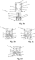
- das Aufspreizen des Einbohrtopfs beim Einstecken des Trägerteils, jeweils in einer Schnittansicht;
- Fign. 3a-3d
- das Verrasten von Einbohrtopf und Trägerteil beim Ineinanderstecken, jeweils in einer Schnittansicht;
- Fign. 4a-4c
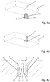
- das Befestigen des Einbohrtopfs an einem Tablar;
- Fign. 5a-5c
- das Befestigen des Trägerteils an einer Korpuswand;
- Fign. 6a-6c
- das Befestigen des Tablars an der Korpuswand mittels des Tablarverbinders von
Fig. 1 ; - Fig. 7
- eine Schnittansicht des im Tablar verankerten Tablarverbinders;
- Fig. 8
- eine zweite Ausführungsform eines erfindungsgemäßen Tablarverbinders mit einem aufspreizbaren Einbohrtopf und einem Trägerteil; und
- Fign. 9a-9c
- das Befestigen des Tablarverbinders von
Fig. 8 an einer Korpuswand. - In der folgenden Figurenbeschreibung werden für gleiche bzw. funktionsgleiche Bauteile identische Bezugszeichen verwendet.
- Der in
Fig. 1 gezeigte Tablarverbinder 1 dient zum Befestigen eines Tablars 2 (Fig. 4 ) an einer Korpuswand 3 (Fig. 5 ) und umfasst einen einstückigen Einbohrtopf 4 zum Einsetzen in eine unterseitige, randoffene Bohrung 5 des Tablars 2 und ein einstückiges Trägerteil 6 zum Befestigen in einer Bohrung 7 der Korpuswand 3. Vorzugsweise ist der Einbohrtopf 4 aus Kunststoff und das Trägerteil 6 aus Zinkdruckguss. Das Tablar 2 und die Korpuswand 3 sind beispielsweise Holzfaserplatten. - Der Einbohrtopf 4 weist einen Topfboden 8, eine stirnseitige Topföffnung 9 und in seiner Umfangswand einen zur Topföffnung 9 hin offenen Längsschlitz 10 auf, der sich bis zum Topfboden 8 erstreckt und in Richtung auf den Topfboden 8 verjüngt ist. Statt wie gezeigt geschlossen, könnte der Topfboden 8 auch offen sein. Die beiden an den Längsschlitz 10 angrenzenden Umfangswandabschnitte 11 des Einbohrtopfs 4 weisen außenseitig eine Verrippung in Form von mehreren axial hintereinander angeordneten Umfangsrippen 12 sowie an der Topföffnung 9 zwei radial nach außen vorstehende Randabschnitte 13 zur Tiefenbegrenzung auf. An den Umfangswandabschnitten 11 stehen innenseitig weiterhin zwei Rastfedern 14 ab, die mit ihren freien Enden einander zugewandt und jeweils schräg in Richtung auf den Topfboden 8 gerichtet sind.
- Das Trägerteil 6 weist einen Auflageboden 15 und einen über den Auflageboden 15 hochstehenden Befestigungsschenkel 16 auf. Oberhalb des Auflagebodens 15, aber auf der dem Auflageboden 15 abgewandten Seite des Befestigungsschenkels 16 steht am Befestigungsschenkel 16 ein Steckzapfen 17 ab, der auf seiner Oberseite mit mehreren Keilnasen 18 versehen ist. Etwa auf halber Höhe zwischen Auflageboden 15 und Steckzapfen 17 weist der Befestigungsschenkel 16 an seiner dem Steckzapfen 17 abgewandten Seite ein etwa V-förmiges Spreizelement 19 mit zwei seitlichen Spreizvorsprüngen 20 auf (
Fig. 3 ), die - gesehen in Richtung fort vom Auflageboden 15 - jeweils schräg in Richtung fort voneinander vorstehen. Wie unten noch näher beschrieben, bildet der oberhalb des Steckzapfens 17 liegende obere Wandabschnitt 16a des Befestigungsschenkels 16 eine Anschlagfläche, die gegenüber dem unterhalb des Steckzapfens 17 liegenden unteren Wandabschnitt 16b um ca. 20° abgewinkelt ist. - Der Einbohrtopf 4 mit seinem Längsschlitz 10 und das Trägerteil 6 mit seinem Befestigungsschenkel 16 sind ineinander steckbar. Wie in
Fign. 2a bis 2c gezeigt, werden beim Ineinanderstecken die beiden an den Längsschlitz 10 angrenzenden Umfangswandabschnitte 11 des Einbohrtopfs 4 durch den verjüngten Befestigungsschenkel 16 nach außen aufgespreizt. Die inFig. 2c gezeigte Steckendposition ist erreicht, wenn die Randabschnitte 13 am Auflageboden 15 anliegen. - Wie in
Fign. 3a bis 3d gezeigt, werden beim Ineinanderstecken die Rastfedern 14 durch die Spreizvorsprünge 20 elastisch nach außen ausgelenkt. In der Steckendposition sind die Spreizvorsprünge 20 und die Rastfedern 14 aneinander vorbeigeschoben, so dass die Rastfedern 14 zurückfedern und die Spreizvorsprünge 20 rastend hintergreifen, genauer gesagt in Rastmulden 21 am Spreizelement 19 formschlüssig einrasten. In der Steckendposition (Fig. 3d ) sind somit der Einbohrtopf 4 und das Trägerteil 6 miteinander verrastet. - In
Fign. 4a-4c ist die Montage des Einbohrtopfes 4 in das Tablar 2 gezeigt. Der Einbohrtopf 4 wird mit seinem zum offenen Rand der Bohrung 5 ausgerichteten Längsschlitz 10 in die Bohrung 5 (Durchmesser 12mm) von Hand eingedrückt, bis die Randabschnitte 13 an der Tablarunterseite zur Anlage kommen und dadurch die Eindrücktiefe begrenzen. In dem inFig. 4c gezeigten eingedrückten Zustand sind die Umfangsrippen 12 noch nicht in die Wandung der Bohrung 5, also in den Holzwerkstoff des Tablars 2, eingedrückt, so dass der Einbohrtopf 4 von Hand noch jederzeit durch Verdrehen ausgerichtet werden kann. - In
Fign. 5a-5c ist die Montage des Trägerteils 6 an der Korpuswand 3 gezeigt. Das Trägerteil 6 wird mit seinem Steckzapfen 17 in die Bohrung 7 (Durchmesser 5mm) der Korpuswand 3 zunächst schräg eingesteckt, bis der obere Wandabschnitt 16a an der Korpuswand 3 anliegt. Dann wird das Trägerteil 6 um ca. 20° nach unten verkippt, bis der untere Wandabschnitt 16b an der Korpuswand 3 anliegt und der Auflageboden 15 horizontal ausgerichtet ist (Fig. 5c ). Durch das Verkippen werden auch die Keilnasen 18 in die Wandung der Bohrung 7, also in den Holzwerkstoff der Korpuswand 3, eingedrückt. - In den
Fign. 6a bis 6c ist das Befestigen des Tablars 2 an der Korpuswand 3 mittels des Tablarverbinders 1 gezeigt. Das Tablar 2 wird mit seinem Einbohrtopf 4 von oben auf das in der Korpuswand 3 verankerte Trägerteil 6 eingehängt, wobei der Einbohrtopf 4 mit seinem Längsschlitz 10 auf den Befestigungsschenkel 16 des Trägerteils 6 gesteckt wird. Schräge Führungsflächen 22, 23 am Einbohrtopf 4 und am Befestigungsschenkel 16 bewirken beim Einhängen, dass der Einbohrtopf 4 in Richtung auf den Steckzapfen 17 gezogen wird und dadurch das Tablar 2 spaltfrei an der Korpuswand 3 anliegt. In der inFig. 6c gezeigten Steckendposition ist einerseits der Einbohrtopf 4 durch die Rastfedern 14 im Trägerteil 6 verrastet (verclipst). Andererseits sind, wie inFig. 7 gezeigt, die beiden Umfangswandabschnitte 11 des Einbohrtopfs 4 durch den verjüngten Befestigungsschenkel 16 nach außen aufgespreizt und dadurch die Umfangsrippen 12 in die Wandung der Bohrung 5, also in den Holzwerkstoff des Tablars 2, eingedrückt. Der Einbohrtopf 4 ist so in der Bohrung 3 fest verankert. - Vom Tablarverbinder der
Fig. 1 unterscheidet sich der inFig. 8 gezeigte Tablarverbinder 1 dadurch, dass hier das Trägerteil 6 statt eines Steckzapfens ein Durchgangsloch 24 für eine Schraube 25 aufweist. InFign. 9a-9c ist die Montage des Trägerteils 6 an der Korpuswand 3 gezeigt, indem die das Durchgangsloch 24 durchgreifende Schraube 25 in die Bohrung 7 der Korpuswand 3 eingeschraubt wird.
Claims (10)
- Verbinder (1), insbesondere Tablarverbinder, mit einem Einbohrtopf (4) zum Einsetzen in eine unterseitige, randoffene Bohrung (5) eines ersten Bauteils (2) und mit einem Trägerteil (6) zum Befestigen in einer Bohrung (7) eines zweiten Bauteils (3), wobei der Einbohrtopf (4) einen Topfboden (8), eine Topföffnung (9) und in seiner Umfangswand einen bis zur Topföffnung (8) hin offenen Längsschlitz (10) aufweist, wobei das Trägerteil (6) einen Auflageboden (15), einen über den Auflageboden (15) hochstehenden Befestigungsschenkel (16) und ein Spreizelement (19) aufweist und wobei der Einbohrtopf (4) mit seinem Längsschlitz (10) und das Trägerteil (6) mit seinem Befestigungsschenkel (11) ineinander steckbar sind,
dadurch gekennzeichnet,
dass der Einbohrtopf (4) an seinen Umfangswandabschnitten innenseitig zwei nach außen abspreizbare Rastfedern (14) aufweist, die mit ihren freien Enden einander zugewandt und jeweils schräg in Richtung auf den Topfboden (8) gerichtet sind, wobei beim Ineinanderstecken von Einbohrtopf (4) und Trägerteil (6) die Rastfedern (14) durch das Spreizelement (19) ausgelenkt werden und in der Steckendposition hinter dem Spreizelement (19) verrastet sind. - Verbinder nach Anspruch 1, dadurch gekennzeichnet, dass der Längsschlitz (10) in Richtung auf den Topfboden (8) und/oder der Befestigungsschenkel (16) in Richtung fort vom Auflageboden (15) verjüngt sind, so dass beim Ineinanderstecken von Einbohrtopf (4) und Trägerteil (6) die beiden an den Längsschlitz (10) angrenzenden Umfangswandabschnitte (11) des Einbohrtopfs (4) durch den Befestigungsschenkel (16) nach außen aufgespreizt werden.
- Verbinder nach Anspruch 1 oder 2, dadurch gekennzeichnet, dass die Umfangswandabschnitte (11) des Einbohrtopfs (4) außenseitig eine Verrippung (12) aufweisen.
- Verbinder nach einem der vorhergehenden Ansprüche, dadurch gekennzeichnet, dass am Einbohrtopf (4) und/oder am Befestigungsschenkel (16) schräg zur Steckrichtung verlaufende Führungsflächen (22, 23) vorgesehen sind, die beim Ineinanderstecken von Einbohrtopf (4) und Trägerteil (6) ein seitliches Anziehen von Einbohrtopf (4) und Trägerteil (6) quer zur Steckrichtung bewirken.
- Verbinder nach einem der vorhergehenden Ansprüche, dadurch gekennzeichnet, dass der Einbohrtopf (4) an seiner Topföffnung (9) mindestens einen radial nach außen vorstehenden Randabschnitt (13), insbesondere mehrere Randabschnitte (13), aufweist.
- Verbinder nach einem der vorhergehenden Ansprüche, dadurch gekennzeichnet, dass sich der Längsschlitz (10) bis zum Topfboden (8) erstreckt.
- Verbinder nach einem der vorhergehenden Ansprüche, dadurch gekennzeichnet, dass der Befestigungsschenkel (16) des Trägerteils (6) einen Steckzapfen (17) zum Einstecken in die Bohrung (7) des zweiten Bauteils (3) aufweist.
- Verbinder nach einem der Ansprüche 1 bis 6, dadurch gekennzeichnet, dass der Befestigungsschenkel (16) des Trägerteils (6) ein Durchgangsloch (24) für eine Schraube (25) zum Einschrauben in die Bohrung (7) des zweiten Bauteils (3) aufweist.
- Anordnung aufweisend ein erstes Bauteil (2), insbesondere Tablar, mit einer unterseitigen, randoffenen Bohrung (5), ein zweites Bauteil (3), insbesondere Korpuswand, mit einer Bohrung (7) und einen Verbinder (1) nach einem der vorhergehenden Ansprüche, wobei der Einbohrtopf (4) in die Bohrung (5) des ersten Bauteils (2) eingesetzt ist, wobei das Trägerteil (6) mit seinem Befestigungsschenkel (17) in der Bohrung (7) des zweiten Bauteils (3) befestigt ist und wobei der Einbohrtopf (4) auf den Befestigungsschenkel (16) des Trägerteils (6) unter Aufspreizen der beiden Umfangswandabschnitte (11) des Einbohrtopfs (4) und/oder unter Verrastung des Trägerteils (6) eingehängt ist.
- Anordnung nach Anspruch 9, dadurch gekennzeichnet, dass das erste und/oder das zweite Bauteil (2, 3) aus Holz oder aus einem Holzfaserstoff gebildet sind.
Priority Applications (1)
| Application Number | Priority Date | Filing Date | Title |
|---|---|---|---|
| PL16174920T PL3153720T3 (pl) | 2015-10-05 | 2016-06-17 | Łącznik do półek z puszką rozpieraną |
Applications Claiming Priority (1)
| Application Number | Priority Date | Filing Date | Title |
|---|---|---|---|
| DE202015105232.4U DE202015105232U1 (de) | 2015-10-05 | 2015-10-05 | Tablarverbinder mit aufspreizbarem Einbohrtopf |
Publications (2)
| Publication Number | Publication Date |
|---|---|
| EP3153720A1 EP3153720A1 (de) | 2017-04-12 |
| EP3153720B1 true EP3153720B1 (de) | 2019-05-22 |
Family
ID=54432227
Family Applications (1)
| Application Number | Title | Priority Date | Filing Date |
|---|---|---|---|
| EP16174920.5A Not-in-force EP3153720B1 (de) | 2015-10-05 | 2016-06-17 | Tablarverbinder mit aufspreizbarem einbohrtopf |
Country Status (4)
| Country | Link |
|---|---|
| EP (1) | EP3153720B1 (de) |
| DE (1) | DE202015105232U1 (de) |
| DK (1) | DK3153720T3 (de) |
| PL (1) | PL3153720T3 (de) |
Families Citing this family (2)
| Publication number | Priority date | Publication date | Assignee | Title |
|---|---|---|---|---|
| DE202016008513U1 (de) | 2016-03-11 | 2018-03-19 | Martin Lachner | Hülse zum Einbringen in eine Öffnung |
| IT201900009219A1 (it) * | 2019-06-17 | 2020-12-17 | Ferramenta Livenza Soc A Responsabilita Limitata | Elemento di supporto per ripiani di mobili |
Family Cites Families (6)
| Publication number | Priority date | Publication date | Assignee | Title |
|---|---|---|---|---|
| DE9407537U1 (de) * | 1994-05-06 | 1994-08-04 | Paul Hettich Gmbh & Co., 32278 Kirchlengern | Beschlag zum lösbaren Verbinden zweier Möbelteile |
| DE29611421U1 (de) * | 1996-07-01 | 1996-09-05 | Häfele GmbH & Co, 72202 Nagold | Beschlag für Sandwichplatten |
| DE20002307U1 (de) * | 2000-02-10 | 2000-04-06 | Hettich-Heinze GmbH & Co. KG, 32139 Spenge | Verbindungsbeschlag |
| DE10229300B3 (de) * | 2002-06-29 | 2004-03-25 | Werthmüller Systeme Geisa GmbH & Co.KG | Verbindungssystem für Bauteile, insbesondere für Möbelteile |
| ITPN20030037U1 (it) * | 2003-11-14 | 2005-05-15 | Livenza Ferramenta Srl | Dispositivo reggi-piano perfezionato |
| DE202007009771U1 (de) | 2007-07-13 | 2007-09-20 | Häfele GmbH & Co KG | Verbindungsbeschlag für Platten, insbesondere für Tablare |
-
2015
- 2015-10-05 DE DE202015105232.4U patent/DE202015105232U1/de not_active Expired - Lifetime
-
2016
- 2016-06-17 DK DK16174920.5T patent/DK3153720T3/da active
- 2016-06-17 PL PL16174920T patent/PL3153720T3/pl unknown
- 2016-06-17 EP EP16174920.5A patent/EP3153720B1/de not_active Not-in-force
Non-Patent Citations (1)
| Title |
|---|
| None * |
Also Published As
| Publication number | Publication date |
|---|---|
| DK3153720T3 (da) | 2019-08-26 |
| EP3153720A1 (de) | 2017-04-12 |
| DE202015105232U1 (de) | 2015-10-16 |
| PL3153720T3 (pl) | 2019-11-29 |
Similar Documents
| Publication | Publication Date | Title |
|---|---|---|
| EP3443234B1 (de) | Beschlag zum lösbaren verbinden zweier möbelteile | |
| DE102004036621B4 (de) | Spreizniet | |
| EP2808566A1 (de) | Spreizverbinder | |
| WO2020173664A1 (de) | Spreizverbinder | |
| EP2792274B1 (de) | Fachbodenträger mit zweistufiger Abstützung | |
| DE202013012442U1 (de) | Trägerkörper für einen Bremsbelag einer Scheibenbremse mit Tilgermasse zur Veränderung der Schwingung | |
| EP3401556A1 (de) | Frontblenden-verbindungsbeschlag | |
| DE202015105329U1 (de) | Dübelanordnung für eine Vorrichtung zum Verbinden zweier Möbelelemente | |
| EP3153720A1 (de) | Tablarverbinder mit aufspreizbarem einbohrtopf | |
| EP3592993B1 (de) | Spannverbinder und befestigungsanordnung mit einem solchen | |
| AT519920B1 (de) | Befestigungsvorrichtung | |
| EP4018100B1 (de) | Verbindungsbeschlag | |
| AT508384B1 (de) | Befestigungsvorrichtung für möbelbeschläge | |
| DE102011004315A1 (de) | Vorrichtung zum Einbau einer Geschirrspülmaschine in eine Einbaunische | |
| BE1028531B1 (de) | Befestigungseinrichtung, Verfahren, Anordnung und Schaltschrank | |
| DE202005007258U1 (de) | Anordnung zum Befestigen einer Fußleiste an einer Wand | |
| EP2787220A2 (de) | Befestigungselement für den Möbelbau | |
| AT508385B1 (de) | Befestigungsvorrichtung für möbelbeschläge | |
| EP3093937A1 (de) | Sockelteil für elektrische installationsgeräte | |
| DE19647209C2 (de) | Befestigungsvorrichtung aus Kunststoff | |
| DE102010016434B4 (de) | Clip zur Befestigung einer Leiste an einem Trägerteil, insbesondere an einem Kraftfahrzeug | |
| DE102013206168B3 (de) | Befestigungseinrichtung | |
| DE10227398B4 (de) | Tragring eines elektrischen Installationsgerätes | |
| DE102011053675A1 (de) | Wandbefestiger | |
| EP4715227A1 (de) | Befestigungsvorrichtung, montageeinheit, anordnung mit einer montageeinheit und verwendung einer befestigungsvorrichtung oder montageeinheit |
Legal Events
| Date | Code | Title | Description |
|---|---|---|---|
| PUAI | Public reference made under article 153(3) epc to a published international application that has entered the european phase |
Free format text: ORIGINAL CODE: 0009012 |
|
| STAA | Information on the status of an ep patent application or granted ep patent |
Free format text: STATUS: THE APPLICATION HAS BEEN PUBLISHED |
|
| AK | Designated contracting states |
Kind code of ref document: A1 Designated state(s): AL AT BE BG CH CY CZ DE DK EE ES FI FR GB GR HR HU IE IS IT LI LT LU LV MC MK MT NL NO PL PT RO RS SE SI SK SM TR |
|
| AX | Request for extension of the european patent |
Extension state: BA ME |
|
| STAA | Information on the status of an ep patent application or granted ep patent |
Free format text: STATUS: REQUEST FOR EXAMINATION WAS MADE |
|
| 17P | Request for examination filed |
Effective date: 20171012 |
|
| RBV | Designated contracting states (corrected) |
Designated state(s): AL AT BE BG CH CY CZ DE DK EE ES FI FR GB GR HR HU IE IS IT LI LT LU LV MC MK MT NL NO PL PT RO RS SE SI SK SM TR |
|
| STAA | Information on the status of an ep patent application or granted ep patent |
Free format text: STATUS: EXAMINATION IS IN PROGRESS |
|
| 17Q | First examination report despatched |
Effective date: 20180412 |
|
| GRAP | Despatch of communication of intention to grant a patent |
Free format text: ORIGINAL CODE: EPIDOSNIGR1 |
|
| STAA | Information on the status of an ep patent application or granted ep patent |
Free format text: STATUS: GRANT OF PATENT IS INTENDED |
|
| INTG | Intention to grant announced |
Effective date: 20190129 |
|
| GRAS | Grant fee paid |
Free format text: ORIGINAL CODE: EPIDOSNIGR3 |
|
| GRAA | (expected) grant |
Free format text: ORIGINAL CODE: 0009210 |
|
| STAA | Information on the status of an ep patent application or granted ep patent |
Free format text: STATUS: THE PATENT HAS BEEN GRANTED |
|
| AK | Designated contracting states |
Kind code of ref document: B1 Designated state(s): AL AT BE BG CH CY CZ DE DK EE ES FI FR GB GR HR HU IE IS IT LI LT LU LV MC MK MT NL NO PL PT RO RS SE SI SK SM TR |
|
| REG | Reference to a national code |
Ref country code: GB Ref legal event code: FG4D Free format text: NOT ENGLISH |
|
| REG | Reference to a national code |
Ref country code: CH Ref legal event code: EP |
|
| REG | Reference to a national code |
Ref country code: IE Ref legal event code: FG4D Free format text: LANGUAGE OF EP DOCUMENT: GERMAN |
|
| REG | Reference to a national code |
Ref country code: DE Ref legal event code: R096 Ref document number: 502016004756 Country of ref document: DE |
|
| REG | Reference to a national code |
Ref country code: AT Ref legal event code: REF Ref document number: 1136467 Country of ref document: AT Kind code of ref document: T Effective date: 20190615 |
|
| REG | Reference to a national code |
Ref country code: DK Ref legal event code: T3 Effective date: 20190822 |
|
| REG | Reference to a national code |
Ref country code: NL Ref legal event code: MP Effective date: 20190522 |
|
| REG | Reference to a national code |
Ref country code: LT Ref legal event code: MG4D |
|
| PG25 | Lapsed in a contracting state [announced via postgrant information from national office to epo] |
Ref country code: LT Free format text: LAPSE BECAUSE OF FAILURE TO SUBMIT A TRANSLATION OF THE DESCRIPTION OR TO PAY THE FEE WITHIN THE PRESCRIBED TIME-LIMIT Effective date: 20190522 Ref country code: FI Free format text: LAPSE BECAUSE OF FAILURE TO SUBMIT A TRANSLATION OF THE DESCRIPTION OR TO PAY THE FEE WITHIN THE PRESCRIBED TIME-LIMIT Effective date: 20190522 Ref country code: NL Free format text: LAPSE BECAUSE OF FAILURE TO SUBMIT A TRANSLATION OF THE DESCRIPTION OR TO PAY THE FEE WITHIN THE PRESCRIBED TIME-LIMIT Effective date: 20190522 Ref country code: AL Free format text: LAPSE BECAUSE OF FAILURE TO SUBMIT A TRANSLATION OF THE DESCRIPTION OR TO PAY THE FEE WITHIN THE PRESCRIBED TIME-LIMIT Effective date: 20190522 Ref country code: ES Free format text: LAPSE BECAUSE OF FAILURE TO SUBMIT A TRANSLATION OF THE DESCRIPTION OR TO PAY THE FEE WITHIN THE PRESCRIBED TIME-LIMIT Effective date: 20190522 Ref country code: SE Free format text: LAPSE BECAUSE OF FAILURE TO SUBMIT A TRANSLATION OF THE DESCRIPTION OR TO PAY THE FEE WITHIN THE PRESCRIBED TIME-LIMIT Effective date: 20190522 Ref country code: HR Free format text: LAPSE BECAUSE OF FAILURE TO SUBMIT A TRANSLATION OF THE DESCRIPTION OR TO PAY THE FEE WITHIN THE PRESCRIBED TIME-LIMIT Effective date: 20190522 Ref country code: PT Free format text: LAPSE BECAUSE OF FAILURE TO SUBMIT A TRANSLATION OF THE DESCRIPTION OR TO PAY THE FEE WITHIN THE PRESCRIBED TIME-LIMIT Effective date: 20190922 Ref country code: NO Free format text: LAPSE BECAUSE OF FAILURE TO SUBMIT A TRANSLATION OF THE DESCRIPTION OR TO PAY THE FEE WITHIN THE PRESCRIBED TIME-LIMIT Effective date: 20190822 |
|
| PG25 | Lapsed in a contracting state [announced via postgrant information from national office to epo] |
Ref country code: GR Free format text: LAPSE BECAUSE OF FAILURE TO SUBMIT A TRANSLATION OF THE DESCRIPTION OR TO PAY THE FEE WITHIN THE PRESCRIBED TIME-LIMIT Effective date: 20190823 Ref country code: LV Free format text: LAPSE BECAUSE OF FAILURE TO SUBMIT A TRANSLATION OF THE DESCRIPTION OR TO PAY THE FEE WITHIN THE PRESCRIBED TIME-LIMIT Effective date: 20190522 Ref country code: RS Free format text: LAPSE BECAUSE OF FAILURE TO SUBMIT A TRANSLATION OF THE DESCRIPTION OR TO PAY THE FEE WITHIN THE PRESCRIBED TIME-LIMIT Effective date: 20190522 Ref country code: BG Free format text: LAPSE BECAUSE OF FAILURE TO SUBMIT A TRANSLATION OF THE DESCRIPTION OR TO PAY THE FEE WITHIN THE PRESCRIBED TIME-LIMIT Effective date: 20190822 |
|
| PG25 | Lapsed in a contracting state [announced via postgrant information from national office to epo] |
Ref country code: SK Free format text: LAPSE BECAUSE OF FAILURE TO SUBMIT A TRANSLATION OF THE DESCRIPTION OR TO PAY THE FEE WITHIN THE PRESCRIBED TIME-LIMIT Effective date: 20190522 Ref country code: EE Free format text: LAPSE BECAUSE OF FAILURE TO SUBMIT A TRANSLATION OF THE DESCRIPTION OR TO PAY THE FEE WITHIN THE PRESCRIBED TIME-LIMIT Effective date: 20190522 Ref country code: CZ Free format text: LAPSE BECAUSE OF FAILURE TO SUBMIT A TRANSLATION OF THE DESCRIPTION OR TO PAY THE FEE WITHIN THE PRESCRIBED TIME-LIMIT Effective date: 20190522 Ref country code: RO Free format text: LAPSE BECAUSE OF FAILURE TO SUBMIT A TRANSLATION OF THE DESCRIPTION OR TO PAY THE FEE WITHIN THE PRESCRIBED TIME-LIMIT Effective date: 20190522 |
|
| REG | Reference to a national code |
Ref country code: CH Ref legal event code: PL |
|
| REG | Reference to a national code |
Ref country code: DE Ref legal event code: R097 Ref document number: 502016004756 Country of ref document: DE |
|
| PG25 | Lapsed in a contracting state [announced via postgrant information from national office to epo] |
Ref country code: SM Free format text: LAPSE BECAUSE OF FAILURE TO SUBMIT A TRANSLATION OF THE DESCRIPTION OR TO PAY THE FEE WITHIN THE PRESCRIBED TIME-LIMIT Effective date: 20190522 Ref country code: MC Free format text: LAPSE BECAUSE OF FAILURE TO SUBMIT A TRANSLATION OF THE DESCRIPTION OR TO PAY THE FEE WITHIN THE PRESCRIBED TIME-LIMIT Effective date: 20190522 |
|
| PLBE | No opposition filed within time limit |
Free format text: ORIGINAL CODE: 0009261 |
|
| REG | Reference to a national code |
Ref country code: BE Ref legal event code: MM Effective date: 20190630 |
|
| STAA | Information on the status of an ep patent application or granted ep patent |
Free format text: STATUS: NO OPPOSITION FILED WITHIN TIME LIMIT |
|
| PG25 | Lapsed in a contracting state [announced via postgrant information from national office to epo] |
Ref country code: TR Free format text: LAPSE BECAUSE OF FAILURE TO SUBMIT A TRANSLATION OF THE DESCRIPTION OR TO PAY THE FEE WITHIN THE PRESCRIBED TIME-LIMIT Effective date: 20190522 |
|
| 26N | No opposition filed |
Effective date: 20200225 |
|
| PG25 | Lapsed in a contracting state [announced via postgrant information from national office to epo] |
Ref country code: IE Free format text: LAPSE BECAUSE OF NON-PAYMENT OF DUE FEES Effective date: 20190617 |
|
| PG25 | Lapsed in a contracting state [announced via postgrant information from national office to epo] |
Ref country code: LI Free format text: LAPSE BECAUSE OF NON-PAYMENT OF DUE FEES Effective date: 20190630 Ref country code: BE Free format text: LAPSE BECAUSE OF NON-PAYMENT OF DUE FEES Effective date: 20190630 Ref country code: CH Free format text: LAPSE BECAUSE OF NON-PAYMENT OF DUE FEES Effective date: 20190630 Ref country code: LU Free format text: LAPSE BECAUSE OF NON-PAYMENT OF DUE FEES Effective date: 20190617 Ref country code: SI Free format text: LAPSE BECAUSE OF FAILURE TO SUBMIT A TRANSLATION OF THE DESCRIPTION OR TO PAY THE FEE WITHIN THE PRESCRIBED TIME-LIMIT Effective date: 20190522 |
|
| PG25 | Lapsed in a contracting state [announced via postgrant information from national office to epo] |
Ref country code: CY Free format text: LAPSE BECAUSE OF FAILURE TO SUBMIT A TRANSLATION OF THE DESCRIPTION OR TO PAY THE FEE WITHIN THE PRESCRIBED TIME-LIMIT Effective date: 20190522 |
|
| PG25 | Lapsed in a contracting state [announced via postgrant information from national office to epo] |
Ref country code: IS Free format text: LAPSE BECAUSE OF FAILURE TO SUBMIT A TRANSLATION OF THE DESCRIPTION OR TO PAY THE FEE WITHIN THE PRESCRIBED TIME-LIMIT Effective date: 20190922 |
|
| PG25 | Lapsed in a contracting state [announced via postgrant information from national office to epo] |
Ref country code: HU Free format text: LAPSE BECAUSE OF FAILURE TO SUBMIT A TRANSLATION OF THE DESCRIPTION OR TO PAY THE FEE WITHIN THE PRESCRIBED TIME-LIMIT; INVALID AB INITIO Effective date: 20160617 Ref country code: MT Free format text: LAPSE BECAUSE OF FAILURE TO SUBMIT A TRANSLATION OF THE DESCRIPTION OR TO PAY THE FEE WITHIN THE PRESCRIBED TIME-LIMIT Effective date: 20190522 |
|
| PG25 | Lapsed in a contracting state [announced via postgrant information from national office to epo] |
Ref country code: MK Free format text: LAPSE BECAUSE OF FAILURE TO SUBMIT A TRANSLATION OF THE DESCRIPTION OR TO PAY THE FEE WITHIN THE PRESCRIBED TIME-LIMIT Effective date: 20190522 |
|
| PGFP | Annual fee paid to national office [announced via postgrant information from national office to epo] |
Ref country code: GB Payment date: 20220623 Year of fee payment: 7 Ref country code: DK Payment date: 20220623 Year of fee payment: 7 |
|
| REG | Reference to a national code |
Ref country code: AT Ref legal event code: MM01 Ref document number: 1136467 Country of ref document: AT Kind code of ref document: T Effective date: 20210617 |
|
| PGFP | Annual fee paid to national office [announced via postgrant information from national office to epo] |
Ref country code: PL Payment date: 20220420 Year of fee payment: 7 |
|
| PGFP | Annual fee paid to national office [announced via postgrant information from national office to epo] |
Ref country code: FR Payment date: 20220620 Year of fee payment: 7 |
|
| PG25 | Lapsed in a contracting state [announced via postgrant information from national office to epo] |
Ref country code: AT Free format text: LAPSE BECAUSE OF NON-PAYMENT OF DUE FEES Effective date: 20210617 |
|
| PGFP | Annual fee paid to national office [announced via postgrant information from national office to epo] |
Ref country code: IT Payment date: 20220630 Year of fee payment: 7 Ref country code: DE Payment date: 20220628 Year of fee payment: 7 |
|
| P01 | Opt-out of the competence of the unified patent court (upc) registered |
Effective date: 20230630 |
|
| REG | Reference to a national code |
Ref country code: DE Ref legal event code: R119 Ref document number: 502016004756 Country of ref document: DE |
|
| REG | Reference to a national code |
Ref country code: DK Ref legal event code: EBP Effective date: 20230630 |
|
| GBPC | Gb: european patent ceased through non-payment of renewal fee |
Effective date: 20230617 |
|
| PG25 | Lapsed in a contracting state [announced via postgrant information from national office to epo] |
Ref country code: DE Free format text: LAPSE BECAUSE OF NON-PAYMENT OF DUE FEES Effective date: 20240103 Ref country code: GB Free format text: LAPSE BECAUSE OF NON-PAYMENT OF DUE FEES Effective date: 20230617 |
|
| PG25 | Lapsed in a contracting state [announced via postgrant information from national office to epo] |
Ref country code: FR Free format text: LAPSE BECAUSE OF NON-PAYMENT OF DUE FEES Effective date: 20230630 |
|
| PG25 | Lapsed in a contracting state [announced via postgrant information from national office to epo] |
Ref country code: DK Free format text: LAPSE BECAUSE OF NON-PAYMENT OF DUE FEES Effective date: 20230630 |
|
| PG25 | Lapsed in a contracting state [announced via postgrant information from national office to epo] |
Ref country code: IT Free format text: LAPSE BECAUSE OF NON-PAYMENT OF DUE FEES Effective date: 20230617 Ref country code: DK Free format text: LAPSE BECAUSE OF NON-PAYMENT OF DUE FEES Effective date: 20230630 |
|
| PG25 | Lapsed in a contracting state [announced via postgrant information from national office to epo] |
Ref country code: PL Free format text: LAPSE BECAUSE OF NON-PAYMENT OF DUE FEES Effective date: 20230617 |
|
| PG25 | Lapsed in a contracting state [announced via postgrant information from national office to epo] |
Ref country code: PL Free format text: LAPSE BECAUSE OF NON-PAYMENT OF DUE FEES Effective date: 20230617 |