EP3153644A2 - Schwimmbeckenreinigung mit wandkletterfunktion und verfahren dafür - Google Patents
Schwimmbeckenreinigung mit wandkletterfunktion und verfahren dafür Download PDFInfo
- Publication number
- EP3153644A2 EP3153644A2 EP16190973.4A EP16190973A EP3153644A2 EP 3153644 A2 EP3153644 A2 EP 3153644A2 EP 16190973 A EP16190973 A EP 16190973A EP 3153644 A2 EP3153644 A2 EP 3153644A2
- Authority
- EP
- European Patent Office
- Prior art keywords
- rolling mechanism
- housing
- swimming pool
- pool cleaner
- coupled
- Prior art date
- Legal status (The legal status is an assumption and is not a legal conclusion. Google has not performed a legal analysis and makes no representation as to the accuracy of the status listed.)
- Granted
Links
Images


Classifications
-
- E—FIXED CONSTRUCTIONS
- E04—BUILDING
- E04H—BUILDINGS OR LIKE STRUCTURES FOR PARTICULAR PURPOSES; SWIMMING OR SPLASH BATHS OR POOLS; MASTS; FENCING; TENTS OR CANOPIES, IN GENERAL
- E04H4/00—Swimming or splash baths or pools
- E04H4/14—Parts, details or accessories not otherwise provided for
- E04H4/16—Parts, details or accessories not otherwise provided for specially adapted for cleaning
- E04H4/1654—Self-propelled cleaners
Definitions
- the present application generally relates to a cleaning device for a swimming pool, and more specifically, to a swimming pool cleaning device that has the ability to climb side walls when the transition between the swimming pool floor and the side is sharp.
- pool cleaners Automated swimming pool cleaning devices
- pool cleaners are used for maintaining residential and commercial swimming pools in a clean and attractive condition.
- Pool cleaners have been developed for cleaning and/or dislodging settled debris from the floor and side wall surfaces of the swimming pool, thereby substantially reducing the need for manual vacumning and/or brushing of the floor and side wall surfaces of the swimming pool.
- a typical pool cleaner may include a housing and a drive member.
- the drive member may attach to the housing usually through a connection to a chassis.
- the drive member may include wheels, endless loop tracks and combinations thereof each. In the case of a belt or endless loop track, the track may wrap around the drive and/or idler wheels or rollers.
- the housing is generally coupled to a swimming pool water filtration system by a hose.
- the swimming pool water filtration system may power the drive members causing the pool cleaning device to travel about within the swimming pool to dislodge and collect settled debris.
- swimming pool surface may be made of rough pebble or smooth tiles.
- the transition between the swimming pool floor and wall could be a generous radius or a sharp angle with no transition. Without any assistance, pool cleaners can climb only at a swimming pool surface whose coefficient of friction is greater than 1. That is extremely hard to achieve especially in a wet environment where there is little to no transition between the swimming pool floor and wall.
- an automated swimming pool cleaner has a housing having an inlet formed on a bottom surface thereof.
- a drive mechanism is located within the housing.
- a first rolling mechanism is coupled to a bottom section of the housing.
- a second rolling mechanism is coupled to the bottom section of the housing.
- a third rolling mechanism is coupled to the bottom section of the housing between the first rolling mechanism and the second rolling mechanism.
- the third rolling mechanism extends lower from the housing than the first rolling mechanism and the second rolling mechanism allowing the automated swimming pool cleaner to pivot about the third rolling mechanism.
- the drive mechanism rotates at least one of the first rolling mechanism, the second rolling mechanism, or the third rolling mechanism.
- an automated swimming pool cleaner has a housing.
- a pump is located within the housing.
- An inlet is formed on a bottom surface of the housing for sucking up of dirt and debris into the housing through a vacuum created by the pump.
- a first rolling mechanism is coupled to a bottom front section of the housing.
- a second rolling mechanism is coupled to a bottom rear section of the housing.
- a third rolling mechanism is coupled to a bottom section of the housing between the first rolling mechanism and the second rolling mechanism. The third rolling mechanism extends lower from the housing than the first rolling mechanism and the second rolling mechanism to allow the automated swimming pool cleaner to pivot about the third rolling mechanism.
- a drive mechanism is located within the housing rotating at least one of the first rolling mechanism, the second rolling mechanism, or the third rolling mechanism.
- an automated swimming pool cleaner has a housing.
- a pump is located within the housing.
- An inlet is formed on a bottom surface of the housing for sucking up of dirt and debris into the housing through a vacuum created by the pump.
- a first rolling mechanism is coupled to a bottom section of the housing.
- a second rolling mechanism is coupled to the bottom section of the housing, wherein the first rolling mechanism and the second rolling mechanism are located on a first plane level on the bottom section of the housing.
- a third rolling mechanism is coupled to the bottom middle section of the housing. The third rolling mechanism is located on a second plane level on the bottom section of the housing. The second plane level is lower on the housing than the first plane level to allow the automated swimming pool cleaner to pivot about the third rolling mechanism.
- Embodiments of the exemplary system and method provide an automated swimming pool cleaner (hereinafter pool cleaner) that has enhanced wall climbing capabilities.
- the pool cleaner may climb a side wall of the swimming pool whether a transition between the swimming pool floor and wall is at a generous radius or at a sharp angle with little to no transition.
- the pool cleaner has at least one rotating element positioned between a front wheel set and a rear wheel set which may allow the pool cleaner to rock.
- the rocking ability may allow the pool cleaner to lift up a front section of the pool cleaner when the front section hits the side wall. This may allow the pool cleaner to obtain better traction in order to climb the side wall of the swimming pool.
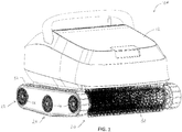
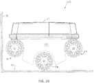
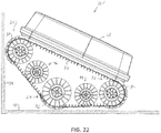
- pool cleaner 10A an automated swimming pool cleaner 10A (hereinafter pool cleaner 10A ) is shown.
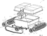
- the pool cleaner 10A has a housing 12. Located within an interior 14 of the housing 12 is a pump 16.
- the pump 16 may be used to create a vacuum. When the pump 16 is active, the pump 16 creates a vacuum that causes dirt and debris to be sucked into the housing 12 through one or more an intakes 18.
- the pool cleaner 10A may have a first rolling mechanism 20 located in a bottom area of a front section of the housing 12.
- a second rolling mechanism 22 may be located in a bottom area of a rear section of the housing 12.
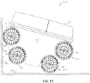
- a third rolling mechanism 24 may be located in the bottom area of the housing 12 between the first rolling mechanism 20 and the second rolling mechanism 22. While FIGs . 1-4 , show the third rolling mechanism 24 to be in the middle of the bottom area of the housing 12 , the third rolling mechanism 24 may be positioned anywhere between the first rolling mechanism 20 and the second rolling mechanism 22.
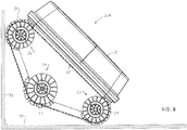
- the pool cleaner 10A is able to pivot about the third rolling mechanism 24. This may allow the pool cleaner 10A to lift up and raise the front section of the pool cleaner 10A when the front section hits the side wall of the swimming pool.
- the third rolling mechanism 24 is positioned lower on the bottom section of the housing 12 thereby allowing the pool cleaner 10A to pivot about the third rolling mechanism 24 in order to lift up and raise the front section of the pool cleaner 10A when the front section hits the side wall of the swimming pool.
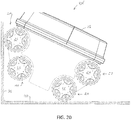
- the first rolling mechanism 20, second rolling mechanism 22 and third rolling mechanism 24 may each be formed of a pair of wheels 26, a roller 28, a combination of the pair of wheels 26 and the roller 28 or similar rolling devices.
- Brushing elements 30 may extend from an exterior surface of the roller 28. The brushing elements 30 may be used to stir up and encouraging dirt and debris to enter intakes 18 in the housing 12.
- a track 32 may be positioned around opposing ends of portions of the first rolling mechanism 20, second rolling mechanism 22 and third rolling mechanism 24. The track 32 may be used to increase the traction of the pool cleaner 10A .
- the pump 16 may be used to power a drive system 34.
- the drive system 34 may be used to rotate one or more of the first rolling mechanism 20, second rolling mechanism 22 and/or third rolling mechanism 24.
- the drive system 34 may engage and rotate a gear 36 formed on the first rolling mechanism 20, second rolling mechanism 22 and/or third rolling mechanism 24 causing the first rolling mechanism 20, second rolling mechanism 22 and/or third rolling mechanism 24 to rotate and moving the pool cleaner 10A .
- the third rolling mechanism 24 protrudes further down allowing the pool cleaner 10A to pivot about the third rolling mechanism 24.
- the third rolling mechanism 24 may be positioned lower on the bottom section of the housing 12 than the first rolling mechanism 20 and second rolling mechanism 22 thereby allowing the pool cleaner 10A to pivot about the third rolling mechanism 24.
- the first rolling mechanism 20 and second rolling mechanism 22 may be attached to the bottom area of the housing 12 on a first plane level.
- the third rolling mechanism 24 may be attached to the bottom section of the housing 12 at a second plane level wherein the second plane level would be at a lower level than the first plane level. This may allow the third rolling mechanism 24 to protrude further down from the housing 12 allowing the pool cleaner 10 to pivot about the third rolling mechanism 24.
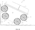
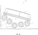
- the pool cleaner 10A may move about the floor 42 of the swimming pool.
- the pool cleaner 10A may balance about the third rolling mechanism 24.
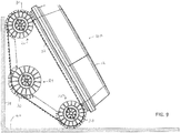
- the pool cleaner 10A pivots about the third rolling mechanism 24, lifting up and raising the front section of the pool cleaner 10A . This may allow the first rolling mechanism 20 to engage the side wall 38 while the second rolling mechanism 22 engages the floor 40 enhancing the climbing ability of the pool cleaner 10A .
- the pool cleaner 10B has a plate member 42 extending down from the housing 12.
- the plate member 42 may be used to protect the first, second and third rolling mechanisms 20, 22 and 24 respectively, as well as to provide stability by preventing the pool cleaner 10B from tipping over when engaging the side wall 38 as shown in FIG. 12 .
- the pool cleaner 10C has a first rolling mechanism 20, second rolling mechanism 22, third rolling mechanism 24 and a fourth rolling mechanism 44.
- the fourth rolling mechanism 44 may be formed of a pair of wheels 26, a roller 28, a combination of the pair of wheels 26 and the roller 28 or similar rolling devices. Brushing elements 30 may extend from an exterior surface of the roller 28 of the fourth rolling mechanism 44.
- a track 32 may be positioned around opposing ends of portions of the first rolling mechanism 20, second rolling mechanism 22, third rolling mechanism 24 and fourth rolling mechanism 44.
- the third rolling mechanism 24 and the fourth rolling mechanism 44 may be positioned between the first rolling mechanism 20 and the second rolling mechanism 22.
- the first rolling mechanism 20 and second rolling mechanism 22 may be attached to the bottom area of the housing 12 on a first plane level.
- the third rolling mechanism 24 and the fourth rolling mechanism 44 may be attached to the bottom section of the housing 12 at a second plane level wherein the second plane level would be at a lower level than the first plane level. This may allow the third and fourth rolling mechanism 22 and 24 respectively to extend further down allowing the pool cleaner 10 to pivot about the third and fourth rolling mechanisms 24 and 44.
- the pool cleaner 10C may move about the floor 40 of the swimming pool.
- the pool cleaner 10C may balance about the third and fourth rolling mechanisms 24 and 44.
- the pool cleaner 10 pivots about the third rolling mechanisms 24, lifting up and raising the front section of the pool cleaner 10C .
- This may allow the first rolling mechanism 20 to engage the side wall 38 while the third rolling mechanism 22 engages the floor 40 enhancing the climbing ability of the pool cleaner 10C .
- the second rolling mechanism 22 may engage the floor 42 which may help to prevent the pool cleaner 10C from tipping over while the first and fourth rolling mechanisms 20 and 44 engage the side wall 38 which may enhance the climbing ability of the pool cleaner 10C .
- the pool cleaner 10D has a plate member 42 extending down from the housing 12.
- the plate member 42 may be used to protect the first, second, third and fourth rolling mechanisms 20, 22, 24 and 44 respectively, as well as to provide stability by preventing the pool cleaner 10 from tipping over when engaging the side wall 38.
- the pool cleaner 10E has a plate member 42 extending down from the housing 12.
- the plate member 42 may be used to protect the first, second, third and fourth rolling mechanisms 20, 22, 24 and 44 respectively, as well as to provide stability by preventing the pool cleaner 10E from tipping over when engaging the side wall 38.
- the first, second, third and fourth rolling mechanisms 20, 22, 24 and 44 do not have any brushing elements 30.
- the pool cleaner 10F has a first rolling mechanism 20, second rolling mechanism 22, third rolling mechanism 24, fourth rolling mechanism 44 and a fifth rolling mechanism 46.
- the fifth rolling mechanism 46 may be formed of a pair of wheels 26, a roller 28, a combination of the pair of wheels 26 and the roller 28 or similar rolling devices.
- a track 32 may be positioned around opposing ends of portions of the first rolling mechanism 20, second rolling mechanism 22, third rolling mechanism 24, fourth rolling mechanism 44 and fifth rolling mechanism 46.
- the fourth rolling mechanism 44 and the fifth rolling mechanism 46 may be positioned between the first rolling mechanism 20 and the second rolling mechanism 22.
- the first rolling mechanism 20 and second rolling mechanism 22 may be attached to the bottom area of the housing 12 on a first plane level.
- the fourth rolling mechanism 44 and the fifth rolling mechanism 46 may be attached to the bottom section of the housing 12 at a second plane level wherein the second plane level would be at a lower level than the first plane level.
- the third rolling mechanism 24 may be positioned between the fourth rolling mechanism 44 and the fifth rolling mechanism 46.
- the third rolling mechanism 24 may be attached to the bottom section of the housing 12 at a third plane level wherein the third plane level would be at a lower level than the second plane level. This may allow the third 24 to extend further down allowing the pool cleaner 10F to pivot about the third rolling mechanisms 24.
- the pool cleaner 10F may move about the floor 40 of the swimming pool.
- the pool cleaner 10F may balance about the third rolling mechanisms 24.
- the pool cleaner 10F pivots about the third rolling mechanisms 24, lifting up and raising the front section of the pool cleaner 10F. This may allow the first rolling mechanism 20 to engage the side wall 38 while the third rolling mechanism 22 engages the floor 40 enhancing the climbing ability of the pool cleaner 10F.
- the second, third and fourth rolling mechanisms 22, 24 and 44 respectively may engage the floor 40 which may help to prevent the pool cleaner 10F from tipping over.
- the pool cleaner 10G has a first rolling mechanism 20, second rolling mechanism 22, third rolling mechanism 24, fourth rolling mechanism 44 and fifth rolling mechanism 46.
- no track is used around opposing ends of portions of the first rolling mechanism 20, second rolling mechanism 22, third rolling mechanism 24, fourth rolling mechanism 44 and fifth rolling mechanism 46.
- the pool cleaner 10G has a first rolling mechanism 20, second rolling mechanism 22, third rolling mechanism 24, fourth rolling mechanism 44 and fifth rolling mechanism 46.
- the first rolling mechanism 20, second rolling mechanism 22, third rolling mechanism 24, fourth rolling mechanism 44 and fifth rolling mechanism 46 do not have a track or brushing elements.
Landscapes
- Engineering & Computer Science (AREA)
- Architecture (AREA)
- Civil Engineering (AREA)
- Structural Engineering (AREA)
- Nozzles For Electric Vacuum Cleaners (AREA)
- Cleaning In General (AREA)
- Electric Vacuum Cleaner (AREA)
- Electric Suction Cleaners (AREA)
Applications Claiming Priority (1)
| Application Number | Priority Date | Filing Date | Title |
|---|---|---|---|
| US14/875,349 US10221584B2 (en) | 2015-10-05 | 2015-10-05 | Swimming pool cleaning with wall climbing capability and method therefor |
Publications (3)
| Publication Number | Publication Date |
|---|---|
| EP3153644A2 true EP3153644A2 (de) | 2017-04-12 |
| EP3153644A3 EP3153644A3 (de) | 2017-05-03 |
| EP3153644B1 EP3153644B1 (de) | 2020-04-08 |
Family
ID=57113060
Family Applications (1)
| Application Number | Title | Priority Date | Filing Date |
|---|---|---|---|
| EP16190973.4A Active EP3153644B1 (de) | 2015-10-05 | 2016-09-28 | Schwimmbeckenreinigung mit wandkletterfunktion |
Country Status (4)
| Country | Link |
|---|---|
| US (1) | US10221584B2 (de) |
| EP (1) | EP3153644B1 (de) |
| CN (1) | CN107013058B (de) |
| ES (1) | ES2804130T3 (de) |
Families Citing this family (11)
| Publication number | Priority date | Publication date | Assignee | Title |
|---|---|---|---|---|
| CN108661361A (zh) * | 2018-05-29 | 2018-10-16 | 广东工业大学 | 一种泳池清洁设备 |
| WO2021167872A1 (en) | 2020-02-19 | 2021-08-26 | Pavel Sebor | Automatic pool cleaner |
| USD1008586S1 (en) * | 2022-08-01 | 2023-12-19 | Beijing Smorobot Technology Co., Ltd | Robotic pool cleaner |
| CN115559574A (zh) * | 2022-10-08 | 2023-01-03 | 深圳市思傲拓科技有限公司 | 一种双排水管游泳池机器人及控制方法 |
| USD992844S1 (en) * | 2022-10-11 | 2023-07-18 | Shenzhen Seauto Technology Co., Ltd. | Cleaning robot |
| USD1022362S1 (en) * | 2022-11-22 | 2024-04-09 | Degrii Co., Ltd. | Swimming pool cleaner with controller |
| USD1060904S1 (en) * | 2023-10-24 | 2025-02-04 | Xingmai Innovation Technology (Suzhou) Co., Ltd. | Automatic swimming pool cleaner |
| USD1115197S1 (en) * | 2023-11-27 | 2026-02-24 | Aiper Global Pte. Ltd. | Swimming pool cleaner |
| USD1091029S1 (en) * | 2023-12-19 | 2025-08-26 | Shenzhen Seauto Technology Co., Ltd. | Underwater cleaning robot |
| USD1057329S1 (en) * | 2024-02-02 | 2025-01-07 | Shenzhen Suihai Industrial Co., Ltd. | Pool clean robot |
| CN119292268B (zh) * | 2024-09-29 | 2026-02-10 | 深圳市元鼎智能创新有限公司 | 一种水下自动清洁设备的触底检测方法及设备 |
Family Cites Families (9)
| Publication number | Priority date | Publication date | Assignee | Title |
|---|---|---|---|---|
| FR2584442B1 (fr) * | 1985-07-02 | 1988-01-08 | Puech Frederic | Appareil de nettoyage automatique d'une surface immergee |
| US5099535A (en) * | 1988-02-18 | 1992-03-31 | Daniel J. D. Chauvier | Cleaner for submerged surfaces |
| EP1402135B1 (de) * | 2001-07-03 | 2009-12-16 | Pentair Pool Products, Inc. | Untergestell für ein automatisches schwimmbeckenreinigungsgerät |
| CN2680779Y (zh) * | 2004-02-17 | 2005-02-23 | 王德良 | 泳池清底机 |
| CN201358597Y (zh) * | 2009-02-05 | 2009-12-09 | 付桂兰 | 遥控有序泳池清洁机器人 |
| US8510889B2 (en) * | 2010-10-28 | 2013-08-20 | Wing-kin HUI | Automated pool cleaning vehicle with middle roller |
| US8661594B2 (en) * | 2010-11-03 | 2014-03-04 | Multi Wisdom Limited | Cleaning apparatus for pool cleaning vehicle with endless loop track |
| CN103089040B (zh) * | 2011-11-03 | 2015-11-25 | 东莞智宝文教用品有限公司 | 可连接到潜水式自动化水池清洁机上的清洁结构 |
| US9399877B2 (en) * | 2014-11-21 | 2016-07-26 | Water Tech, LLC | Robotic pool cleaning apparatus |
-
2015
- 2015-10-05 US US14/875,349 patent/US10221584B2/en active Active
-
2016
- 2016-09-28 ES ES16190973T patent/ES2804130T3/es active Active
- 2016-09-28 EP EP16190973.4A patent/EP3153644B1/de active Active
- 2016-09-29 CN CN201610865378.7A patent/CN107013058B/zh active Active
Non-Patent Citations (1)
| Title |
|---|
| None |
Also Published As
| Publication number | Publication date |
|---|---|
| ES2804130T3 (es) | 2021-02-03 |
| EP3153644A3 (de) | 2017-05-03 |
| US20170096826A1 (en) | 2017-04-06 |
| CN107013058A (zh) | 2017-08-04 |
| CN107013058B (zh) | 2019-06-04 |
| EP3153644B1 (de) | 2020-04-08 |
| US10221584B2 (en) | 2019-03-05 |
Similar Documents
| Publication | Publication Date | Title |
|---|---|---|
| EP3153644A2 (de) | Schwimmbeckenreinigung mit wandkletterfunktion und verfahren dafür | |
| EP3301243B1 (de) | Schwimmbeckenreinigungsfahrzeug mit seitlichen aufnahmeklappen und verfahren dafür | |
| US11199016B2 (en) | Swimming pool cleaning vehicle with adjustable rollers to control water flow velocity and method therefor | |
| KR102442057B1 (ko) | 로봇 청소기 | |
| EP2447449B1 (de) | Automatisches Poolreinigungsfahrzeug mit Mittelroller | |
| AU725207B2 (en) | Swimming pool cleaner | |
| AU2022268309B2 (en) | Automatic pool cleaner | |
| US8627532B2 (en) | Pool cleaning vehicle having improved intake port | |
| US8661594B2 (en) | Cleaning apparatus for pool cleaning vehicle with endless loop track | |
| US8065771B2 (en) | Pool cleaning brush | |
| US10400467B2 (en) | Swimming pool cleaning device with obstacle clearing system | |
| US9359782B2 (en) | Automated pool cleaning vehicle with scrubbing elements | |
| EP2743429A1 (de) | Automatisches Poolreinigungsfahrzeug mit Scheuervorrichtung | |
| EP1980686A2 (de) | Schwimmbeckenreiniger mit konturierter Grundfläche | |
| US11821233B2 (en) | Automatic swimming pool cleaners especially adept at climbing and cleaning pool stairs | |
| KR102662323B1 (ko) | 로봇 청소기 | |
| CN114668350B (zh) | 行走装置及清洁设备 | |
| KR102662324B1 (ko) | 로봇 청소기 | |
| CN111920344A (zh) | 机器人越障装置 | |
| EP4045739B1 (de) | Saugreiniger fuer schwimmbecken |
Legal Events
| Date | Code | Title | Description |
|---|---|---|---|
| PUAI | Public reference made under article 153(3) epc to a published international application that has entered the european phase |
Free format text: ORIGINAL CODE: 0009012 |
|
| STAA | Information on the status of an ep patent application or granted ep patent |
Free format text: STATUS: THE APPLICATION HAS BEEN PUBLISHED |
|
| PUAL | Search report despatched |
Free format text: ORIGINAL CODE: 0009013 |
|
| AK | Designated contracting states |
Kind code of ref document: A2 Designated state(s): AL AT BE BG CH CY CZ DE DK EE ES FI FR GB GR HR HU IE IS IT LI LT LU LV MC MK MT NL NO PL PT RO RS SE SI SK SM TR |
|
| AX | Request for extension of the european patent |
Extension state: BA ME |
|
| AK | Designated contracting states |
Kind code of ref document: A3 Designated state(s): AL AT BE BG CH CY CZ DE DK EE ES FI FR GB GR HR HU IE IS IT LI LT LU LV MC MK MT NL NO PL PT RO RS SE SI SK SM TR |
|
| AX | Request for extension of the european patent |
Extension state: BA ME |
|
| RIC1 | Information provided on ipc code assigned before grant |
Ipc: E04H 4/16 20060101AFI20170327BHEP |
|
| STAA | Information on the status of an ep patent application or granted ep patent |
Free format text: STATUS: REQUEST FOR EXAMINATION WAS MADE |
|
| 17P | Request for examination filed |
Effective date: 20171103 |
|
| RBV | Designated contracting states (corrected) |
Designated state(s): AL AT BE BG CH CY CZ DE DK EE ES FI FR GB GR HR HU IE IS IT LI LT LU LV MC MK MT NL NO PL PT RO RS SE SI SK SM TR |
|
| STAA | Information on the status of an ep patent application or granted ep patent |
Free format text: STATUS: EXAMINATION IS IN PROGRESS |
|
| 17Q | First examination report despatched |
Effective date: 20190402 |
|
| GRAP | Despatch of communication of intention to grant a patent |
Free format text: ORIGINAL CODE: EPIDOSNIGR1 |
|
| STAA | Information on the status of an ep patent application or granted ep patent |
Free format text: STATUS: GRANT OF PATENT IS INTENDED |
|
| INTG | Intention to grant announced |
Effective date: 20191028 |
|
| RIN1 | Information on inventor provided before grant (corrected) |
Inventor name: HUI, WING-TAK Inventor name: HUI, ANDREW MATTHEW Inventor name: HUI, WING-KIN |
|
| GRAS | Grant fee paid |
Free format text: ORIGINAL CODE: EPIDOSNIGR3 |
|
| GRAA | (expected) grant |
Free format text: ORIGINAL CODE: 0009210 |
|
| STAA | Information on the status of an ep patent application or granted ep patent |
Free format text: STATUS: THE PATENT HAS BEEN GRANTED |
|
| RAP1 | Party data changed (applicant data changed or rights of an application transferred) |
Owner name: UPWARD SALES LIMITED |
|
| AK | Designated contracting states |
Kind code of ref document: B1 Designated state(s): AL AT BE BG CH CY CZ DE DK EE ES FI FR GB GR HR HU IE IS IT LI LT LU LV MC MK MT NL NO PL PT RO RS SE SI SK SM TR |
|
| REG | Reference to a national code |
Ref country code: CH Ref legal event code: EP Ref country code: AT Ref legal event code: REF Ref document number: 1254582 Country of ref document: AT Kind code of ref document: T Effective date: 20200415 |
|
| REG | Reference to a national code |
Ref country code: DE Ref legal event code: R096 Ref document number: 602016033425 Country of ref document: DE |
|
| REG | Reference to a national code |
Ref country code: IE Ref legal event code: FG4D |
|
| REG | Reference to a national code |
Ref country code: NL Ref legal event code: MP Effective date: 20200408 |
|
| REG | Reference to a national code |
Ref country code: LT Ref legal event code: MG4D |
|
| PG25 | Lapsed in a contracting state [announced via postgrant information from national office to epo] |
Ref country code: FI Free format text: LAPSE BECAUSE OF FAILURE TO SUBMIT A TRANSLATION OF THE DESCRIPTION OR TO PAY THE FEE WITHIN THE PRESCRIBED TIME-LIMIT Effective date: 20200408 Ref country code: GR Free format text: LAPSE BECAUSE OF FAILURE TO SUBMIT A TRANSLATION OF THE DESCRIPTION OR TO PAY THE FEE WITHIN THE PRESCRIBED TIME-LIMIT Effective date: 20200709 Ref country code: NO Free format text: LAPSE BECAUSE OF FAILURE TO SUBMIT A TRANSLATION OF THE DESCRIPTION OR TO PAY THE FEE WITHIN THE PRESCRIBED TIME-LIMIT Effective date: 20200708 Ref country code: LT Free format text: LAPSE BECAUSE OF FAILURE TO SUBMIT A TRANSLATION OF THE DESCRIPTION OR TO PAY THE FEE WITHIN THE PRESCRIBED TIME-LIMIT Effective date: 20200408 Ref country code: SE Free format text: LAPSE BECAUSE OF FAILURE TO SUBMIT A TRANSLATION OF THE DESCRIPTION OR TO PAY THE FEE WITHIN THE PRESCRIBED TIME-LIMIT Effective date: 20200408 Ref country code: NL Free format text: LAPSE BECAUSE OF FAILURE TO SUBMIT A TRANSLATION OF THE DESCRIPTION OR TO PAY THE FEE WITHIN THE PRESCRIBED TIME-LIMIT Effective date: 20200408 Ref country code: IS Free format text: LAPSE BECAUSE OF FAILURE TO SUBMIT A TRANSLATION OF THE DESCRIPTION OR TO PAY THE FEE WITHIN THE PRESCRIBED TIME-LIMIT Effective date: 20200808 Ref country code: PT Free format text: LAPSE BECAUSE OF FAILURE TO SUBMIT A TRANSLATION OF THE DESCRIPTION OR TO PAY THE FEE WITHIN THE PRESCRIBED TIME-LIMIT Effective date: 20200817 |
|
| REG | Reference to a national code |
Ref country code: AT Ref legal event code: MK05 Ref document number: 1254582 Country of ref document: AT Kind code of ref document: T Effective date: 20200408 |
|
| PG25 | Lapsed in a contracting state [announced via postgrant information from national office to epo] |
Ref country code: RS Free format text: LAPSE BECAUSE OF FAILURE TO SUBMIT A TRANSLATION OF THE DESCRIPTION OR TO PAY THE FEE WITHIN THE PRESCRIBED TIME-LIMIT Effective date: 20200408 Ref country code: BG Free format text: LAPSE BECAUSE OF FAILURE TO SUBMIT A TRANSLATION OF THE DESCRIPTION OR TO PAY THE FEE WITHIN THE PRESCRIBED TIME-LIMIT Effective date: 20200708 Ref country code: LV Free format text: LAPSE BECAUSE OF FAILURE TO SUBMIT A TRANSLATION OF THE DESCRIPTION OR TO PAY THE FEE WITHIN THE PRESCRIBED TIME-LIMIT Effective date: 20200408 Ref country code: HR Free format text: LAPSE BECAUSE OF FAILURE TO SUBMIT A TRANSLATION OF THE DESCRIPTION OR TO PAY THE FEE WITHIN THE PRESCRIBED TIME-LIMIT Effective date: 20200408 |
|
| PG25 | Lapsed in a contracting state [announced via postgrant information from national office to epo] |
Ref country code: AL Free format text: LAPSE BECAUSE OF FAILURE TO SUBMIT A TRANSLATION OF THE DESCRIPTION OR TO PAY THE FEE WITHIN THE PRESCRIBED TIME-LIMIT Effective date: 20200408 |
|
| REG | Reference to a national code |
Ref country code: DE Ref legal event code: R097 Ref document number: 602016033425 Country of ref document: DE |
|
| PG25 | Lapsed in a contracting state [announced via postgrant information from national office to epo] |
Ref country code: CZ Free format text: LAPSE BECAUSE OF FAILURE TO SUBMIT A TRANSLATION OF THE DESCRIPTION OR TO PAY THE FEE WITHIN THE PRESCRIBED TIME-LIMIT Effective date: 20200408 Ref country code: DK Free format text: LAPSE BECAUSE OF FAILURE TO SUBMIT A TRANSLATION OF THE DESCRIPTION OR TO PAY THE FEE WITHIN THE PRESCRIBED TIME-LIMIT Effective date: 20200408 Ref country code: RO Free format text: LAPSE BECAUSE OF FAILURE TO SUBMIT A TRANSLATION OF THE DESCRIPTION OR TO PAY THE FEE WITHIN THE PRESCRIBED TIME-LIMIT Effective date: 20200408 Ref country code: IT Free format text: LAPSE BECAUSE OF FAILURE TO SUBMIT A TRANSLATION OF THE DESCRIPTION OR TO PAY THE FEE WITHIN THE PRESCRIBED TIME-LIMIT Effective date: 20200408 Ref country code: SM Free format text: LAPSE BECAUSE OF FAILURE TO SUBMIT A TRANSLATION OF THE DESCRIPTION OR TO PAY THE FEE WITHIN THE PRESCRIBED TIME-LIMIT Effective date: 20200408 Ref country code: EE Free format text: LAPSE BECAUSE OF FAILURE TO SUBMIT A TRANSLATION OF THE DESCRIPTION OR TO PAY THE FEE WITHIN THE PRESCRIBED TIME-LIMIT Effective date: 20200408 Ref country code: AT Free format text: LAPSE BECAUSE OF FAILURE TO SUBMIT A TRANSLATION OF THE DESCRIPTION OR TO PAY THE FEE WITHIN THE PRESCRIBED TIME-LIMIT Effective date: 20200408 |
|
| REG | Reference to a national code |
Ref country code: ES Ref legal event code: FG2A Ref document number: 2804130 Country of ref document: ES Kind code of ref document: T3 Effective date: 20210203 |
|
| PLBE | No opposition filed within time limit |
Free format text: ORIGINAL CODE: 0009261 |
|
| STAA | Information on the status of an ep patent application or granted ep patent |
Free format text: STATUS: NO OPPOSITION FILED WITHIN TIME LIMIT |
|
| PG25 | Lapsed in a contracting state [announced via postgrant information from national office to epo] |
Ref country code: SK Free format text: LAPSE BECAUSE OF FAILURE TO SUBMIT A TRANSLATION OF THE DESCRIPTION OR TO PAY THE FEE WITHIN THE PRESCRIBED TIME-LIMIT Effective date: 20200408 Ref country code: PL Free format text: LAPSE BECAUSE OF FAILURE TO SUBMIT A TRANSLATION OF THE DESCRIPTION OR TO PAY THE FEE WITHIN THE PRESCRIBED TIME-LIMIT Effective date: 20200408 |
|
| 26N | No opposition filed |
Effective date: 20210112 |
|
| PG25 | Lapsed in a contracting state [announced via postgrant information from national office to epo] |
Ref country code: MC Free format text: LAPSE BECAUSE OF FAILURE TO SUBMIT A TRANSLATION OF THE DESCRIPTION OR TO PAY THE FEE WITHIN THE PRESCRIBED TIME-LIMIT Effective date: 20200408 |
|
| REG | Reference to a national code |
Ref country code: CH Ref legal event code: PL |
|
| GBPC | Gb: european patent ceased through non-payment of renewal fee |
Effective date: 20200928 |
|
| PG25 | Lapsed in a contracting state [announced via postgrant information from national office to epo] |
Ref country code: SI Free format text: LAPSE BECAUSE OF FAILURE TO SUBMIT A TRANSLATION OF THE DESCRIPTION OR TO PAY THE FEE WITHIN THE PRESCRIBED TIME-LIMIT Effective date: 20200408 |
|
| REG | Reference to a national code |
Ref country code: BE Ref legal event code: MM Effective date: 20200930 |
|
| PG25 | Lapsed in a contracting state [announced via postgrant information from national office to epo] |
Ref country code: LU Free format text: LAPSE BECAUSE OF NON-PAYMENT OF DUE FEES Effective date: 20200928 |
|
| PG25 | Lapsed in a contracting state [announced via postgrant information from national office to epo] |
Ref country code: BE Free format text: LAPSE BECAUSE OF NON-PAYMENT OF DUE FEES Effective date: 20200930 Ref country code: CH Free format text: LAPSE BECAUSE OF NON-PAYMENT OF DUE FEES Effective date: 20200930 Ref country code: GB Free format text: LAPSE BECAUSE OF NON-PAYMENT OF DUE FEES Effective date: 20200928 Ref country code: LI Free format text: LAPSE BECAUSE OF NON-PAYMENT OF DUE FEES Effective date: 20200930 Ref country code: IE Free format text: LAPSE BECAUSE OF NON-PAYMENT OF DUE FEES Effective date: 20200928 |
|
| PG25 | Lapsed in a contracting state [announced via postgrant information from national office to epo] |
Ref country code: TR Free format text: LAPSE BECAUSE OF FAILURE TO SUBMIT A TRANSLATION OF THE DESCRIPTION OR TO PAY THE FEE WITHIN THE PRESCRIBED TIME-LIMIT Effective date: 20200408 Ref country code: MT Free format text: LAPSE BECAUSE OF FAILURE TO SUBMIT A TRANSLATION OF THE DESCRIPTION OR TO PAY THE FEE WITHIN THE PRESCRIBED TIME-LIMIT Effective date: 20200408 Ref country code: CY Free format text: LAPSE BECAUSE OF FAILURE TO SUBMIT A TRANSLATION OF THE DESCRIPTION OR TO PAY THE FEE WITHIN THE PRESCRIBED TIME-LIMIT Effective date: 20200408 |
|
| PG25 | Lapsed in a contracting state [announced via postgrant information from national office to epo] |
Ref country code: MK Free format text: LAPSE BECAUSE OF FAILURE TO SUBMIT A TRANSLATION OF THE DESCRIPTION OR TO PAY THE FEE WITHIN THE PRESCRIBED TIME-LIMIT Effective date: 20200408 |
|
| PGFP | Annual fee paid to national office [announced via postgrant information from national office to epo] |
Ref country code: DE Payment date: 20250929 Year of fee payment: 10 |
|
| PGFP | Annual fee paid to national office [announced via postgrant information from national office to epo] |
Ref country code: FR Payment date: 20250925 Year of fee payment: 10 |
|
| PGFP | Annual fee paid to national office [announced via postgrant information from national office to epo] |
Ref country code: ES Payment date: 20251001 Year of fee payment: 10 |