EP3301243B1 - Schwimmbeckenreinigungsfahrzeug mit seitlichen aufnahmeklappen und verfahren dafür - Google Patents
Schwimmbeckenreinigungsfahrzeug mit seitlichen aufnahmeklappen und verfahren dafür Download PDFInfo
- Publication number
- EP3301243B1 EP3301243B1 EP17192527.4A EP17192527A EP3301243B1 EP 3301243 B1 EP3301243 B1 EP 3301243B1 EP 17192527 A EP17192527 A EP 17192527A EP 3301243 B1 EP3301243 B1 EP 3301243B1
- Authority
- EP
- European Patent Office
- Prior art keywords
- flap
- swimming pool
- housing
- pool cleaner
- accordance
- Prior art date
- Legal status (The legal status is an assumption and is not a legal conclusion. Google has not performed a legal analysis and makes no representation as to the accuracy of the status listed.)
- Active
Links
Images




Classifications
-
- E—FIXED CONSTRUCTIONS
- E04—BUILDING
- E04H—BUILDINGS OR LIKE STRUCTURES FOR PARTICULAR PURPOSES; SWIMMING OR SPLASH BATHS OR POOLS; MASTS; FENCING; TENTS OR CANOPIES, IN GENERAL
- E04H4/00—Swimming or splash baths or pools
- E04H4/14—Parts, details or accessories not otherwise provided for
- E04H4/16—Parts, details or accessories not otherwise provided for specially adapted for cleaning
- E04H4/1654—Self-propelled cleaners
Definitions
- the present application generally relates to a cleaning device for a swimming pool, and more specifically, to a swimming pool cleaning device that has side intake flaps which are used to increase the suction cleaning path width of the swimming pool cleaning device.
- pool cleaners are used for maintaining residential and commercial swimming pools in a clean and attractive condition. Pool cleaners have been developed for cleaning and/or dislodging settled debris from the floor and side wall surfaces of the swimming pool, thereby substantially reducing the need for manual vacuuming and/or brushing of the floor and side wall surfaces of the swimming pool.
- a typical pool cleaner may include a housing and a drive member.
- the drive member may attach to the housing usually through a connection to a chassis.
- the drive member may include wheels, endless loop tracks and combinations thereof each. In the case of a belt or endless loop track, the track may wrap around the drive and/or idler wheels or rollers.
- the drive member may also be used to create at least a partial vacuum so that water will be encourage to enter one or more intake ports formed in the housing.
- the drive member may be powered by a power source coupled to the drive member.
- the housing may be coupled to a swimming pool water filtration system by a hose.
- the swimming pool water filtration system may power the drive members causing the pool cleaning device to travel about within the swimming pool to dislodge and collect settled debris.
- a typical pool cleaner moves along the surface of the pool.
- Water may flow into the one or more intake ports.
- the water may flow through a filter bag stored within the housing and exit out the housing through an outlet port.
- the water/debris which enters the one or more inlet ports may exit out of the housing to the swimming pool water filtration system.
- a typical pool cleaner generally moves in a randomly pattern along the floor and/or walls of the swimming pool during cleaning.
- the suction cleaning path of the pool cleaner is limited to the width of pool cleaner. While smaller pool cleaners may be more maneuverable, the smaller suction cleaning path correlates to the pool cleaner needing a substantial amount of time to clean the entire pool surface.
- the present invention relates to an automated swimming pool cleaner.
- the automated swimming pool cleaner has a housing having an inlet formed on a bottom surface thereof. At least one slot is formed in a bottom side surface of the housing.
- a flap is in fluid communication with the slot, wherein the flap diverges outward from the slot and is fan shaped.
- a wheel is coupled to the flap. The wheel keeps a bottom surface of the flap a minimum distance above a floor/wall of a swimming pool.
- an interior of the flap is angled downward so that a distance above a bottom surface of the flap decreases as the flap extends outward away from the housing.
- an interior of the flap is angled downward so that a distance between a top surface of the interior of the flap and a bottom surface of the flap decreases as the flap extends away from the housing.
- an inlet channel extends from the flap.
- the inlet channel is configured to slide within the slot.
- a wheel well is formed within an interior of the flap wherein the wheel is rotatably coupled within the wheel well.
- a pair of grooves is formed within the wheel well, and an axle assembly is coupled to the wheel, the axle assembly being held within the pair of grooves.
- connecting devices secure the inlet channel within the slot.
- connecting devices secure the flap to the housing.
- Embodiments of the exemplary system and method provide an automated swimming pool cleaner (hereinafter pool cleaner) that has side intake flaps.
- pool cleaner an automated swimming pool cleaner
- the side intake flaps may be used to increase the suction cleaning path width of the pool cleaner.
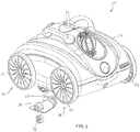
- an automated swimming pool cleaner 10 (hereinafter pool cleaner 10 ) may be seen.
- the pool cleaner 10 may have a housing 12. Located within an interior of the housing 12 may be a pump 14.
- the pump 14 may be used to create a vacuum. When the pump 14 is active, the pump 14 creates a vacuum that causes dirt and debris to be sucked into the housing 12 through one or more intakes 16.
- the pool cleaner 10 could also be coupled to a pool filtration system.
- the pool filtration system may be used to generate the vacuum within the interior of the housing 12 to suck up dirt and debris on a floor/wall of the swimming pool.
- the pool cleaner 10 may have a first rolling mechanism 18 located in a bottom area of a front section of the housing 12.
- a second rolling mechanism 20 may be located in a bottom area of a rear section of the housing 12.
- the first rolling mechanism 18 and the second rolling mechanism 20 may each be formed of a pair of wheels 22, a roller, a combination of the pair of wheels 22 and the roller or similar rolling devices.
- the pump 14 may be used to power a drive system 24.
- the drive system 24 may be used to rotate one or more of the first rolling mechanism 18 and/or second rolling mechanism 20.
- the vacuum generated by pool filtration system may be used to power the drive system 24.
- One or more rolling brushes 26 may be located in the bottom area of the housing 12 between the first rolling mechanism 18 and the second rolling mechanism 20.
- the rolling brushes 26 may be used to stir up and encourage dirt and debris to enter intakes 16 in the housing 12.
- the drive system 24 may be used to rotate the rolling brushes 26.
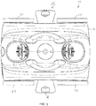
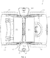
- One or more intakes 16 may be formed in a bottom section of the housing 12. In the embodiments shown in the Figs. 1-7 , the intake 16 may be formed in a bottom central area of the housing 12. The intake 16 may run along the width of the bottom section of the housing 12. When the pump 14 and/or the pool filtration system creates a vacuum within the housing 12, water as well as any dirt and/or debris may be drawn into the intake 16.
- One or more slots 28 may be formed in bottom side surfaces of the housing 12.
- the slots 28 may be in fluid communication with the interior of the housing 12.
- the slots 28 may extend into and be in fluid communication with the intake 16 which may run along the width of the bottom section of the housing 12.
- the pump 14 and/or the pool filtration system creates a vacuum within the housing 12, water as well as any dirt and/or debris may be drawn into the slots 28 and/or intake 16.
- one or more flaps 30 may be coupled to the housing 12.
- the flap 30 may be formed of a light-weight but sturdy material.
- the flaps 30 may be formed of Polyvinyl chloride (PVC) or other types of plastic.
- PVC Polyvinyl chloride
- the flap 30 may be configured to force water to go under the flap 30 before it enters the slot 28. By doing so, the water forced under the flap 30 may carry the dirt and other debris under the flap 30 and effectively increase the suction cleaning path width of the pool cleaner 10.
- the flap 30 may be configured to diverge outward from the slot 28.
- the flap 30 may be fan shaped when looking downward on the flap 30 such that a width of the flap 30 increases as the flap 30 extends further away from the housing 12 of the pool cleaner 10.
- the flap 30 has an open bottom surface exposing a hollow interior 30B of the flap 30.
- the interior 30B of the flap 30 may be angled downward.
- the interior 30B of the flap 30 may be angled downward such that a distance above the bottom surface decreases as the flap 30 extends further away from the pool cleaner 10.
- the interior 30B of the flap 30 may be wedge shaped wherein the distance between a top surface 30C of the interior 30B and the bottom surface decreases as the flap 30 extends further away from the pool cleaner 10. This wedge shape configuration may help to funnel water towards the slot 28 thereby helping to prevent any partial loss of suction within the housing 12.
- Each flap 30 may be attached to the housing 12.
- the flap 30 may have an inlet channel 30D.
- the inlet channel 30D may extend out from the flap 30.
- the inlet channel 30D may be dimensioned to be inserted into a slot 28 thereby allowing water to flow under the flap 30 and into the slot 28.
- the above is given as an example and should not be seen in a limiting manner.
- the flap 30 may be attached to the housing 12 in other manners without departing from the spirit and scope of the present invention.
- connecting devices 32 such as rivets, screws and similar devices may be used to secure the flap 30 to the housing 12.
- the connecting devices 32 may be used alone or in combination with the slot 28. As may be seen in the FIGs., the connecting devices 32 may be used to further secure the inlet channel 30D within the slot 28.
- a wheel 34 may be rotatably coupled to the flap 30.
- the wheel 34 may be used to keep the bottom surface of the flap 30 a minimum distance above the floor/wall of the swimming pool.
- a wheel well 36 may be formed in the interior 30B of the flap 30.
- the wheel well 36 may be an indentation formed in the interior 30B of the flap 30.
- the wheel well 36 may be formed in the distal end of the interior 30B of the flap 30.
- An axle assembly 38 may be used to rotatably couple the wheel 34 to the flap 30.
- the axle assembly 38 may be rotatably secured within the wheel well 36.
- a pair of grooves 40 may be formed within wheel well 36. The grooves 40 may house the axle assembly 38 and allow the axle assembly and hence the wheel 34 to rotate freely within the wheel well 36.
- the wheel 34 may keep the bottom surface of the flap 30 a minimum distance above the floor/wall of the swimming pool. Since the wheel 34 may keep the bottom surface of the flap 30 above the floor/wall of the swimming pool, water may be force to go under the flap 30 before it enters the slot 28. By doing so, the water forced under the flap 30 may carry the dirt and other debris under the flap 30 with it and effectively increase the suction cleaning path width of the pool cleaner 10. Thus, the flap 30 may improve cleaning efficiency by increasing cleaning path width but without sacrificing the suction power and/or a partial loss of suction.
- the flap 30 may allow for balanced suction through the one or more slots 28 and intakes 16.
Landscapes
- Engineering & Computer Science (AREA)
- Architecture (AREA)
- Civil Engineering (AREA)
- Structural Engineering (AREA)
- Cleaning In General (AREA)
- Cleaning By Liquid Or Steam (AREA)
- Nozzles For Electric Vacuum Cleaners (AREA)
Claims (8)
- Automatischer Schwimmbeckenreiniger (10), umfassend:ein Gehäuse (12) mit einem Einlass (16), der auf einer unteren Fläche davon gebildet ist,mindestens einen Schlitz (28), der in einer unteren Seitenfläche des Gehäuses (12) gebildet ist, dadurch gekennzeichnet, dass der automatische Schwimmbeckenreiniger (10) weiter Folgendes umfasst:eine Klappe (30), die in fluidischer Kommunikation mit dem Schlitz (28) ist, wobei die Klappe (30) nach außen vom Schlitz (28) abweicht und fächerförmig ist; undein Rad (34), das mit der Klappe (30) gekoppelt ist, wobei das Rad (34) eine unter Fläche der Klappe (30) einen minimalen Abstand über einem Boden/einer Wand eines Schwimmbeckens hält.
- Automatischer Schwimmbeckenreiniger (10) nach Anspruch 1, wobei ein Inneres (30B) der Klappe (30) nach unten gewinkelt ist, wobei ein Abstand über einer unteren Fläche der Klappe (30) abnimmt, wenn sich die Klappe (30) nach außen weg vom Gehäuse (12) erstreckt.
- Automatischer Schwimmbeckenreiniger (10) nach Anspruch 1, wobei ein Inneres (30B) der Klappe (30) nach unten gewinkelt ist, wobei ein Abstand zwischen einer oberen Fläche (30C) des Inneren (30B) der Klappe (30) und einer unteren Fläche der Klappe (30) abnimmt, wenn sich die Klappe (30) weg vom Gehäuse (12) erstreckt.
- Automatischer Schwimmbeckenreiniger (10) nach einem der Ansprüche 1 bis 3, umfassend einen Radkasten (36), der innerhalb eines Innern (30B) der Klappe (30) gebildet ist, wobei das Rad (34) drehbar mit dem Radkasten (36) gekoppelt ist.
- Automatischer Schwimmbeckenreiniger (10) nach Anspruch 4, umfassend:ein Paar Nuten (40), die innerhalb des Radkastens (36) gebildet sind; undeine Achsanordnung (38), die an das Rad (34) gekoppelt ist, wobei die Achsanordnung (38) innerhalb des Paars von Nuten (40) gehalten wird.
- Automatischer Schwimmbeckenreiniger (10) nach einem der Ansprüche 1 bis 5, umfassend einen Einlasskanal (30D), der sich von der Klappe (30) erstreckt, wobei der Einlasskanal (30D) konfiguriert ist, um innerhalb des Schlitzes (28) zu gleiten.
- Automatischer Schwimmbeckenreiniger (10) nach Anspruch 6, umfassend Verbindungsvorrichtungen (32), die den Einlasskanal (30D) innerhalb des Schitzes (28) befestigen.
- Automatischer Schwimmbeckenreiniger (10) nach einem der Ansprüche 1 bis 7, umfassend Verbindungsvorrichtungen (32), die die Klappe (30) an das Gehäuse (12) befestigen.
Applications Claiming Priority (1)
| Application Number | Priority Date | Filing Date | Title |
|---|---|---|---|
| US15/274,250 US9809990B1 (en) | 2016-09-23 | 2016-09-23 | Swimming pool cleaning vehicle with side intake flaps and method therefor |
Publications (2)
| Publication Number | Publication Date |
|---|---|
| EP3301243A1 EP3301243A1 (de) | 2018-04-04 |
| EP3301243B1 true EP3301243B1 (de) | 2019-05-01 |
Family
ID=59930278
Family Applications (1)
| Application Number | Title | Priority Date | Filing Date |
|---|---|---|---|
| EP17192527.4A Active EP3301243B1 (de) | 2016-09-23 | 2017-09-22 | Schwimmbeckenreinigungsfahrzeug mit seitlichen aufnahmeklappen und verfahren dafür |
Country Status (4)
| Country | Link |
|---|---|
| US (1) | US9809990B1 (de) |
| EP (1) | EP3301243B1 (de) |
| CN (1) | CN107663958B (de) |
| ES (1) | ES2737997T3 (de) |
Families Citing this family (18)
| Publication number | Priority date | Publication date | Assignee | Title |
|---|---|---|---|---|
| USD858917S1 (en) * | 2018-03-23 | 2019-09-03 | Compurobot Technology Company | Pool cleaner |
| USD849342S1 (en) * | 2018-03-23 | 2019-05-21 | Compurobot Technology Company | Pool cleaner |
| USD849343S1 (en) * | 2018-03-23 | 2019-05-21 | Compurobot Technology Company | Pool cleaner |
| USD876733S1 (en) * | 2018-03-23 | 2020-02-25 | Compurobot Technology Company | Water jet propulsion pool cleaner |
| USD859765S1 (en) * | 2018-03-23 | 2019-09-10 | Compurobot Technology Company | Pool cleaner |
| US10294686B1 (en) * | 2018-04-24 | 2019-05-21 | Water Tech, LLC | Rechargeable robotic pool cleaning apparatus |
| CN109025399B (zh) * | 2018-07-05 | 2020-11-06 | 宁波博尔富泳池设备有限公司 | 一种能清洁除垢的机器人 |
| US10774557B1 (en) | 2019-02-21 | 2020-09-15 | Aquatron Robotic Technology Ltd. | Pool cleaner with selective inlet control |
| CN109914873B (zh) * | 2019-03-28 | 2020-11-10 | 江苏蚨瑞盛达医疗器械有限公司 | 一种户外泳池无需排水的深潜浮泡即时清理机 |
| USD1024465S1 (en) * | 2022-04-19 | 2024-04-23 | Poolelf Smart Technology Co., Ltd. | Swimming pool cleaner |
| USD1027342S1 (en) * | 2022-04-19 | 2024-05-14 | Poolelf Smart Technology Co., Ltd. | Swimming pool cleaner robot |
| USD1083257S1 (en) * | 2022-10-14 | 2025-07-08 | Taizhou Dibiao Technology Co., Ltd. | Cleaning robot |
| USD1051524S1 (en) * | 2023-01-13 | 2024-11-12 | Weiwei Liu | Pool cleaner |
| USD1064466S1 (en) * | 2023-02-14 | 2025-02-25 | Compurobot Technology Company | Pool cleaner |
| USD1124549S1 (en) * | 2023-06-16 | 2026-04-28 | Wybotics Co., Ltd | Pool cleaning device |
| USD1079163S1 (en) * | 2023-06-28 | 2025-06-10 | Ningbo Powerful Pool Equipment Co., Ltd. | Pool cleaner |
| CN221609644U (zh) * | 2023-10-20 | 2024-08-27 | 宁波市普世达泳池用品有限公司 | 一种电动机器人 |
| USD1113017S1 (en) * | 2023-11-21 | 2026-02-10 | Hangzhou Maichi Chushi Purifying Equipment Co., Ltd. | Automatic cleaning robot for swimming pool |
Family Cites Families (15)
| Publication number | Priority date | Publication date | Assignee | Title |
|---|---|---|---|---|
| US3675261A (en) * | 1970-07-06 | 1972-07-11 | Kenneth M Burgess | Pool cleaning apparatus |
| ZA767474B (en) * | 1976-12-15 | 1978-08-30 | W Rasch | Pool cleaners |
| US5197158A (en) * | 1992-04-07 | 1993-03-30 | Philip L. Leslie | Swimming pool cleaner |
| US5725761A (en) * | 1997-02-24 | 1998-03-10 | Phillips; Harold L. | Modular filter / circulation system and traveling main drain for in-ground swimming pools |
| US5882512A (en) * | 1997-11-05 | 1999-03-16 | Baracuda International Corporation | Automatic swimming pool cleaners and associated components and systems |
| US6971136B2 (en) * | 1999-01-25 | 2005-12-06 | Aqua Products, Inc. | Cleaner with high pressure cleaning jets |
| US6412133B1 (en) * | 1999-01-25 | 2002-07-02 | Aqua Products, Inc. | Water jet reversing propulsion and directional controls for automated swimming pool cleaners |
| ES2365729T3 (es) * | 2002-01-18 | 2011-10-10 | Smartpool Incorporated | Dispositivo para la limpieza de piscinas. |
| FR2896005B1 (fr) * | 2006-01-11 | 2008-04-04 | Max Roumagnac | Robot nettoyeur de piscine |
| CN201162365Y (zh) * | 2008-02-19 | 2008-12-10 | 林海 | 一种抽吸式水底清污装置 |
| US8590090B2 (en) * | 2008-09-11 | 2013-11-26 | Aqua Products, Inc. | Adjustable intake port for submersible pool and tank cleaner |
| US9091093B2 (en) * | 2012-07-10 | 2015-07-28 | Aqua Products, Inc. | Internal backwash system for robotic swimming pool cleaner |
| CN203160757U (zh) * | 2013-01-23 | 2013-08-28 | 王建银 | 游泳池底吸污器 |
| US9856669B2 (en) * | 2014-11-24 | 2018-01-02 | Compurobot Technology Company | Advanced pool cleaner construction |
| CN204983774U (zh) * | 2015-05-27 | 2016-01-20 | 明达实业(厦门)有限公司 | 一种池底清洁器的刷子结构 |
-
2016
- 2016-09-23 US US15/274,250 patent/US9809990B1/en active Active
-
2017
- 2017-09-22 ES ES17192527T patent/ES2737997T3/es active Active
- 2017-09-22 EP EP17192527.4A patent/EP3301243B1/de active Active
- 2017-09-22 CN CN201710865592.7A patent/CN107663958B/zh active Active
Also Published As
| Publication number | Publication date |
|---|---|
| CN107663958B (zh) | 2018-10-19 |
| US9809990B1 (en) | 2017-11-07 |
| CN107663958A (zh) | 2018-02-06 |
| ES2737997T3 (es) | 2020-01-17 |
| EP3301243A1 (de) | 2018-04-04 |
Similar Documents
| Publication | Publication Date | Title |
|---|---|---|
| US9809990B1 (en) | Swimming pool cleaning vehicle with side intake flaps and method therefor | |
| US11199016B2 (en) | Swimming pool cleaning vehicle with adjustable rollers to control water flow velocity and method therefor | |
| KR102442057B1 (ko) | 로봇 청소기 | |
| US8397331B2 (en) | Cleaner apparatus for a submerged surface with a protuberance which accelerates the inlet flow | |
| US10221584B2 (en) | Swimming pool cleaning with wall climbing capability and method therefor | |
| KR102271785B1 (ko) | 로봇 진공 청소기 | |
| CN106175587B (zh) | 机器人吸尘器 | |
| EP1980687A2 (de) | Schwimmbeckensäuberungsfahrzeug mit verbessertem Einlasskanal | |
| US20160168872A1 (en) | Advanced pool cleaner construction | |
| WO2010003247A1 (en) | Pool vacuum cleaner unit | |
| EP4025106B1 (de) | Staubsaugerroboter und ein verfahren in einem staubsaugerroboter | |
| US10863878B2 (en) | System and method for improved recirculating vacuum with removable nozzle | |
| US20080295264A1 (en) | Swimming pool cleaning vehicle | |
| EP2186969B1 (de) | Schwimmbeckenreinigungsfahrzeug mit Seitenklappen und -kanälen | |
| US20170325645A1 (en) | Suction nozzle and electric vacuum cleaner including the same | |
| KR100628387B1 (ko) | 진공청소기의 흡입브러시 | |
| US8709245B2 (en) | Pool cleaning vehicle having side vents and ducts | |
| KR102662324B1 (ko) | 로봇 청소기 | |
| KR20110039638A (ko) | 흡착가이드를 구비한 로봇 청소기 |
Legal Events
| Date | Code | Title | Description |
|---|---|---|---|
| PUAI | Public reference made under article 153(3) epc to a published international application that has entered the european phase |
Free format text: ORIGINAL CODE: 0009012 |
|
| STAA | Information on the status of an ep patent application or granted ep patent |
Free format text: STATUS: THE APPLICATION HAS BEEN PUBLISHED |
|
| AK | Designated contracting states |
Kind code of ref document: A1 Designated state(s): AL AT BE BG CH CY CZ DE DK EE ES FI FR GB GR HR HU IE IS IT LI LT LU LV MC MK MT NL NO PL PT RO RS SE SI SK SM TR |
|
| AX | Request for extension of the european patent |
Extension state: BA ME |
|
| STAA | Information on the status of an ep patent application or granted ep patent |
Free format text: STATUS: REQUEST FOR EXAMINATION WAS MADE |
|
| 17P | Request for examination filed |
Effective date: 20180925 |
|
| RBV | Designated contracting states (corrected) |
Designated state(s): AL AT BE BG CH CY CZ DE DK EE ES FI FR GB GR HR HU IE IS IT LI LT LU LV MC MK MT NL NO PL PT RO RS SE SI SK SM TR |
|
| GRAP | Despatch of communication of intention to grant a patent |
Free format text: ORIGINAL CODE: EPIDOSNIGR1 |
|
| STAA | Information on the status of an ep patent application or granted ep patent |
Free format text: STATUS: GRANT OF PATENT IS INTENDED |
|
| RIC1 | Information provided on ipc code assigned before grant |
Ipc: E04H 4/16 20060101AFI20181031BHEP |
|
| INTG | Intention to grant announced |
Effective date: 20181123 |
|
| RIN1 | Information on inventor provided before grant (corrected) |
Inventor name: HUI, WING-TAK Inventor name: HUI, ANDREW MATTHEW Inventor name: HUI, WING-KIN |
|
| GRAS | Grant fee paid |
Free format text: ORIGINAL CODE: EPIDOSNIGR3 |
|
| GRAA | (expected) grant |
Free format text: ORIGINAL CODE: 0009210 |
|
| STAA | Information on the status of an ep patent application or granted ep patent |
Free format text: STATUS: THE PATENT HAS BEEN GRANTED |
|
| AK | Designated contracting states |
Kind code of ref document: B1 Designated state(s): AL AT BE BG CH CY CZ DE DK EE ES FI FR GB GR HR HU IE IS IT LI LT LU LV MC MK MT NL NO PL PT RO RS SE SI SK SM TR |
|
| REG | Reference to a national code |
Ref country code: GB Ref legal event code: FG4D |
|
| REG | Reference to a national code |
Ref country code: CH Ref legal event code: EP Ref country code: AT Ref legal event code: REF Ref document number: 1127075 Country of ref document: AT Kind code of ref document: T Effective date: 20190515 |
|
| REG | Reference to a national code |
Ref country code: DE Ref legal event code: R096 Ref document number: 602017003645 Country of ref document: DE |
|
| REG | Reference to a national code |
Ref country code: IE Ref legal event code: FG4D |
|
| REG | Reference to a national code |
Ref country code: NL Ref legal event code: MP Effective date: 20190501 |
|
| REG | Reference to a national code |
Ref country code: LT Ref legal event code: MG4D |
|
| PG25 | Lapsed in a contracting state [announced via postgrant information from national office to epo] |
Ref country code: FI Free format text: LAPSE BECAUSE OF FAILURE TO SUBMIT A TRANSLATION OF THE DESCRIPTION OR TO PAY THE FEE WITHIN THE PRESCRIBED TIME-LIMIT Effective date: 20190501 Ref country code: SE Free format text: LAPSE BECAUSE OF FAILURE TO SUBMIT A TRANSLATION OF THE DESCRIPTION OR TO PAY THE FEE WITHIN THE PRESCRIBED TIME-LIMIT Effective date: 20190501 Ref country code: PT Free format text: LAPSE BECAUSE OF FAILURE TO SUBMIT A TRANSLATION OF THE DESCRIPTION OR TO PAY THE FEE WITHIN THE PRESCRIBED TIME-LIMIT Effective date: 20190901 Ref country code: LT Free format text: LAPSE BECAUSE OF FAILURE TO SUBMIT A TRANSLATION OF THE DESCRIPTION OR TO PAY THE FEE WITHIN THE PRESCRIBED TIME-LIMIT Effective date: 20190501 Ref country code: NL Free format text: LAPSE BECAUSE OF FAILURE TO SUBMIT A TRANSLATION OF THE DESCRIPTION OR TO PAY THE FEE WITHIN THE PRESCRIBED TIME-LIMIT Effective date: 20190501 Ref country code: AL Free format text: LAPSE BECAUSE OF FAILURE TO SUBMIT A TRANSLATION OF THE DESCRIPTION OR TO PAY THE FEE WITHIN THE PRESCRIBED TIME-LIMIT Effective date: 20190501 Ref country code: NO Free format text: LAPSE BECAUSE OF FAILURE TO SUBMIT A TRANSLATION OF THE DESCRIPTION OR TO PAY THE FEE WITHIN THE PRESCRIBED TIME-LIMIT Effective date: 20190801 Ref country code: HR Free format text: LAPSE BECAUSE OF FAILURE TO SUBMIT A TRANSLATION OF THE DESCRIPTION OR TO PAY THE FEE WITHIN THE PRESCRIBED TIME-LIMIT Effective date: 20190501 |
|
| PG25 | Lapsed in a contracting state [announced via postgrant information from national office to epo] |
Ref country code: GR Free format text: LAPSE BECAUSE OF FAILURE TO SUBMIT A TRANSLATION OF THE DESCRIPTION OR TO PAY THE FEE WITHIN THE PRESCRIBED TIME-LIMIT Effective date: 20190802 Ref country code: RS Free format text: LAPSE BECAUSE OF FAILURE TO SUBMIT A TRANSLATION OF THE DESCRIPTION OR TO PAY THE FEE WITHIN THE PRESCRIBED TIME-LIMIT Effective date: 20190501 Ref country code: LV Free format text: LAPSE BECAUSE OF FAILURE TO SUBMIT A TRANSLATION OF THE DESCRIPTION OR TO PAY THE FEE WITHIN THE PRESCRIBED TIME-LIMIT Effective date: 20190501 Ref country code: BG Free format text: LAPSE BECAUSE OF FAILURE TO SUBMIT A TRANSLATION OF THE DESCRIPTION OR TO PAY THE FEE WITHIN THE PRESCRIBED TIME-LIMIT Effective date: 20190801 |
|
| REG | Reference to a national code |
Ref country code: AT Ref legal event code: MK05 Ref document number: 1127075 Country of ref document: AT Kind code of ref document: T Effective date: 20190501 |
|
| PG25 | Lapsed in a contracting state [announced via postgrant information from national office to epo] |
Ref country code: IS Free format text: LAPSE BECAUSE OF FAILURE TO SUBMIT A TRANSLATION OF THE DESCRIPTION OR TO PAY THE FEE WITHIN THE PRESCRIBED TIME-LIMIT Effective date: 20190901 |
|
| REG | Reference to a national code |
Ref country code: ES Ref legal event code: FG2A Ref document number: 2737997 Country of ref document: ES Kind code of ref document: T3 Effective date: 20200117 |
|
| PG25 | Lapsed in a contracting state [announced via postgrant information from national office to epo] |
Ref country code: CZ Free format text: LAPSE BECAUSE OF FAILURE TO SUBMIT A TRANSLATION OF THE DESCRIPTION OR TO PAY THE FEE WITHIN THE PRESCRIBED TIME-LIMIT Effective date: 20190501 Ref country code: RO Free format text: LAPSE BECAUSE OF FAILURE TO SUBMIT A TRANSLATION OF THE DESCRIPTION OR TO PAY THE FEE WITHIN THE PRESCRIBED TIME-LIMIT Effective date: 20190501 Ref country code: DK Free format text: LAPSE BECAUSE OF FAILURE TO SUBMIT A TRANSLATION OF THE DESCRIPTION OR TO PAY THE FEE WITHIN THE PRESCRIBED TIME-LIMIT Effective date: 20190501 Ref country code: AT Free format text: LAPSE BECAUSE OF FAILURE TO SUBMIT A TRANSLATION OF THE DESCRIPTION OR TO PAY THE FEE WITHIN THE PRESCRIBED TIME-LIMIT Effective date: 20190501 Ref country code: EE Free format text: LAPSE BECAUSE OF FAILURE TO SUBMIT A TRANSLATION OF THE DESCRIPTION OR TO PAY THE FEE WITHIN THE PRESCRIBED TIME-LIMIT Effective date: 20190501 Ref country code: SK Free format text: LAPSE BECAUSE OF FAILURE TO SUBMIT A TRANSLATION OF THE DESCRIPTION OR TO PAY THE FEE WITHIN THE PRESCRIBED TIME-LIMIT Effective date: 20190501 |
|
| REG | Reference to a national code |
Ref country code: DE Ref legal event code: R097 Ref document number: 602017003645 Country of ref document: DE |
|
| PG25 | Lapsed in a contracting state [announced via postgrant information from national office to epo] |
Ref country code: SM Free format text: LAPSE BECAUSE OF FAILURE TO SUBMIT A TRANSLATION OF THE DESCRIPTION OR TO PAY THE FEE WITHIN THE PRESCRIBED TIME-LIMIT Effective date: 20190501 Ref country code: IT Free format text: LAPSE BECAUSE OF FAILURE TO SUBMIT A TRANSLATION OF THE DESCRIPTION OR TO PAY THE FEE WITHIN THE PRESCRIBED TIME-LIMIT Effective date: 20190501 |
|
| PLBE | No opposition filed within time limit |
Free format text: ORIGINAL CODE: 0009261 |
|
| STAA | Information on the status of an ep patent application or granted ep patent |
Free format text: STATUS: NO OPPOSITION FILED WITHIN TIME LIMIT |
|
| PG25 | Lapsed in a contracting state [announced via postgrant information from national office to epo] |
Ref country code: TR Free format text: LAPSE BECAUSE OF FAILURE TO SUBMIT A TRANSLATION OF THE DESCRIPTION OR TO PAY THE FEE WITHIN THE PRESCRIBED TIME-LIMIT Effective date: 20190501 |
|
| 26N | No opposition filed |
Effective date: 20200204 |
|
| PG25 | Lapsed in a contracting state [announced via postgrant information from national office to epo] |
Ref country code: PL Free format text: LAPSE BECAUSE OF FAILURE TO SUBMIT A TRANSLATION OF THE DESCRIPTION OR TO PAY THE FEE WITHIN THE PRESCRIBED TIME-LIMIT Effective date: 20190501 |
|
| PG25 | Lapsed in a contracting state [announced via postgrant information from national office to epo] |
Ref country code: SI Free format text: LAPSE BECAUSE OF FAILURE TO SUBMIT A TRANSLATION OF THE DESCRIPTION OR TO PAY THE FEE WITHIN THE PRESCRIBED TIME-LIMIT Effective date: 20190501 Ref country code: MC Free format text: LAPSE BECAUSE OF FAILURE TO SUBMIT A TRANSLATION OF THE DESCRIPTION OR TO PAY THE FEE WITHIN THE PRESCRIBED TIME-LIMIT Effective date: 20190501 |
|
| PG25 | Lapsed in a contracting state [announced via postgrant information from national office to epo] |
Ref country code: IE Free format text: LAPSE BECAUSE OF NON-PAYMENT OF DUE FEES Effective date: 20190922 Ref country code: LU Free format text: LAPSE BECAUSE OF NON-PAYMENT OF DUE FEES Effective date: 20190922 |
|
| REG | Reference to a national code |
Ref country code: BE Ref legal event code: MM Effective date: 20190930 |
|
| PG25 | Lapsed in a contracting state [announced via postgrant information from national office to epo] |
Ref country code: BE Free format text: LAPSE BECAUSE OF NON-PAYMENT OF DUE FEES Effective date: 20190930 |
|
| REG | Reference to a national code |
Ref country code: DE Ref legal event code: R082 Ref document number: 602017003645 Country of ref document: DE Representative=s name: CABINET CHAILLOT, FR Ref country code: DE Ref legal event code: R081 Ref document number: 602017003645 Country of ref document: DE Owner name: HUI, WING-KIN MARTIN, HK Free format text: FORMER OWNER: PROFIT LOCK LTD., KWUN TONG, HK |
|
| REG | Reference to a national code |
Ref country code: ES Ref legal event code: PC2A Owner name: HUI WING-KIN MARTIN Effective date: 20210422 |
|
| REG | Reference to a national code |
Ref country code: CH Ref legal event code: PL |
|
| PG25 | Lapsed in a contracting state [announced via postgrant information from national office to epo] |
Ref country code: CY Free format text: LAPSE BECAUSE OF FAILURE TO SUBMIT A TRANSLATION OF THE DESCRIPTION OR TO PAY THE FEE WITHIN THE PRESCRIBED TIME-LIMIT Effective date: 20190501 |
|
| PG25 | Lapsed in a contracting state [announced via postgrant information from national office to epo] |
Ref country code: MT Free format text: LAPSE BECAUSE OF FAILURE TO SUBMIT A TRANSLATION OF THE DESCRIPTION OR TO PAY THE FEE WITHIN THE PRESCRIBED TIME-LIMIT Effective date: 20190501 Ref country code: HU Free format text: LAPSE BECAUSE OF FAILURE TO SUBMIT A TRANSLATION OF THE DESCRIPTION OR TO PAY THE FEE WITHIN THE PRESCRIBED TIME-LIMIT; INVALID AB INITIO Effective date: 20170922 |
|
| PG25 | Lapsed in a contracting state [announced via postgrant information from national office to epo] |
Ref country code: LI Free format text: LAPSE BECAUSE OF NON-PAYMENT OF DUE FEES Effective date: 20200930 Ref country code: CH Free format text: LAPSE BECAUSE OF NON-PAYMENT OF DUE FEES Effective date: 20200930 |
|
| GBPC | Gb: european patent ceased through non-payment of renewal fee |
Effective date: 20210922 |
|
| PG25 | Lapsed in a contracting state [announced via postgrant information from national office to epo] |
Ref country code: MK Free format text: LAPSE BECAUSE OF FAILURE TO SUBMIT A TRANSLATION OF THE DESCRIPTION OR TO PAY THE FEE WITHIN THE PRESCRIBED TIME-LIMIT Effective date: 20190501 |
|
| PG25 | Lapsed in a contracting state [announced via postgrant information from national office to epo] |
Ref country code: GB Free format text: LAPSE BECAUSE OF NON-PAYMENT OF DUE FEES Effective date: 20210922 |
|
| PGFP | Annual fee paid to national office [announced via postgrant information from national office to epo] |
Ref country code: DE Payment date: 20250924 Year of fee payment: 9 |
|
| PGFP | Annual fee paid to national office [announced via postgrant information from national office to epo] |
Ref country code: FR Payment date: 20250912 Year of fee payment: 9 |
|
| PGFP | Annual fee paid to national office [announced via postgrant information from national office to epo] |
Ref country code: ES Payment date: 20251006 Year of fee payment: 9 |