EP3152017B1 - Procédé permettant de faire fonctionner une installation d'usinage de panneaux, et installation d'usinage de panneaux - Google Patents
Procédé permettant de faire fonctionner une installation d'usinage de panneaux, et installation d'usinage de panneaux Download PDFInfo
- Publication number
- EP3152017B1 EP3152017B1 EP15725550.6A EP15725550A EP3152017B1 EP 3152017 B1 EP3152017 B1 EP 3152017B1 EP 15725550 A EP15725550 A EP 15725550A EP 3152017 B1 EP3152017 B1 EP 3152017B1
- Authority
- EP
- European Patent Office
- Prior art keywords
- panel
- detection device
- plate processing
- situation
- area
- Prior art date
- Legal status (The legal status is an assumption and is not a legal conclusion. Google has not performed a legal analysis and makes no representation as to the accuracy of the status listed.)
- Active
Links
- 238000012545 processing Methods 0.000 title claims description 46
- 238000000034 method Methods 0.000 title claims description 29
- 238000009434 installation Methods 0.000 title 2
- 238000001514 detection method Methods 0.000 claims description 38
- 239000000463 material Substances 0.000 claims description 20
- 230000002950 deficient Effects 0.000 claims description 13
- 230000001105 regulatory effect Effects 0.000 claims description 13
- 238000011156 evaluation Methods 0.000 claims description 8
- 230000001133 acceleration Effects 0.000 claims description 4
- 230000006978 adaptation Effects 0.000 claims description 4
- 238000004519 manufacturing process Methods 0.000 claims description 3
- 238000013024 troubleshooting Methods 0.000 claims description 3
- 238000004513 sizing Methods 0.000 description 34
- 230000000875 corresponding effect Effects 0.000 description 12
- 238000005520 cutting process Methods 0.000 description 9
- 230000033001 locomotion Effects 0.000 description 9
- 230000000712 assembly Effects 0.000 description 4
- 238000000429 assembly Methods 0.000 description 4
- 230000006870 function Effects 0.000 description 4
- 230000002452 interceptive effect Effects 0.000 description 4
- 238000002372 labelling Methods 0.000 description 4
- 238000012546 transfer Methods 0.000 description 4
- 230000001960 triggered effect Effects 0.000 description 3
- 238000011161 development Methods 0.000 description 2
- 230000018109 developmental process Effects 0.000 description 2
- 238000010586 diagram Methods 0.000 description 2
- 238000006073 displacement reaction Methods 0.000 description 2
- 230000007257 malfunction Effects 0.000 description 2
- 238000012544 monitoring process Methods 0.000 description 2
- 230000000007 visual effect Effects 0.000 description 2
- 239000002699 waste material Substances 0.000 description 2
- 230000002159 abnormal effect Effects 0.000 description 1
- 238000013475 authorization Methods 0.000 description 1
- 230000004888 barrier function Effects 0.000 description 1
- 239000000969 carrier Substances 0.000 description 1
- 230000000052 comparative effect Effects 0.000 description 1
- 238000004590 computer program Methods 0.000 description 1
- 238000012937 correction Methods 0.000 description 1
- 230000001419 dependent effect Effects 0.000 description 1
- 230000035622 drinking Effects 0.000 description 1
- 238000005259 measurement Methods 0.000 description 1
- 238000003801 milling Methods 0.000 description 1
- 238000012552 review Methods 0.000 description 1
- 239000007921 spray Substances 0.000 description 1
Images

Classifications
-
- F—MECHANICAL ENGINEERING; LIGHTING; HEATING; WEAPONS; BLASTING
- F16—ENGINEERING ELEMENTS AND UNITS; GENERAL MEASURES FOR PRODUCING AND MAINTAINING EFFECTIVE FUNCTIONING OF MACHINES OR INSTALLATIONS; THERMAL INSULATION IN GENERAL
- F16P—SAFETY DEVICES IN GENERAL; SAFETY DEVICES FOR PRESSES
- F16P3/00—Safety devices acting in conjunction with the control or operation of a machine; Control arrangements requiring the simultaneous use of two or more parts of the body
- F16P3/12—Safety devices acting in conjunction with the control or operation of a machine; Control arrangements requiring the simultaneous use of two or more parts of the body with means, e.g. feelers, which in case of the presence of a body part of a person in or near the danger zone influence the control or operation of the machine
- F16P3/14—Safety devices acting in conjunction with the control or operation of a machine; Control arrangements requiring the simultaneous use of two or more parts of the body with means, e.g. feelers, which in case of the presence of a body part of a person in or near the danger zone influence the control or operation of the machine the means being photocells or other devices sensitive without mechanical contact
- F16P3/142—Safety devices acting in conjunction with the control or operation of a machine; Control arrangements requiring the simultaneous use of two or more parts of the body with means, e.g. feelers, which in case of the presence of a body part of a person in or near the danger zone influence the control or operation of the machine the means being photocells or other devices sensitive without mechanical contact using image capturing devices
-
- B—PERFORMING OPERATIONS; TRANSPORTING
- B23—MACHINE TOOLS; METAL-WORKING NOT OTHERWISE PROVIDED FOR
- B23Q—DETAILS, COMPONENTS, OR ACCESSORIES FOR MACHINE TOOLS, e.g. ARRANGEMENTS FOR COPYING OR CONTROLLING; MACHINE TOOLS IN GENERAL CHARACTERISED BY THE CONSTRUCTION OF PARTICULAR DETAILS OR COMPONENTS; COMBINATIONS OR ASSOCIATIONS OF METAL-WORKING MACHINES, NOT DIRECTED TO A PARTICULAR RESULT
- B23Q11/00—Accessories fitted to machine tools for keeping tools or parts of the machine in good working condition or for cooling work; Safety devices specially combined with or arranged in, or specially adapted for use in connection with, machine tools
- B23Q11/0078—Safety devices protecting the operator, e.g. against accident or noise
-
- B—PERFORMING OPERATIONS; TRANSPORTING
- B23—MACHINE TOOLS; METAL-WORKING NOT OTHERWISE PROVIDED FOR
- B23Q—DETAILS, COMPONENTS, OR ACCESSORIES FOR MACHINE TOOLS, e.g. ARRANGEMENTS FOR COPYING OR CONTROLLING; MACHINE TOOLS IN GENERAL CHARACTERISED BY THE CONSTRUCTION OF PARTICULAR DETAILS OR COMPONENTS; COMBINATIONS OR ASSOCIATIONS OF METAL-WORKING MACHINES, NOT DIRECTED TO A PARTICULAR RESULT
- B23Q17/00—Arrangements for observing, indicating or measuring on machine tools
- B23Q17/24—Arrangements for observing, indicating or measuring on machine tools using optics or electromagnetic waves
- B23Q17/2409—Arrangements for indirect observation of the working space using image recording means, e.g. a camera
-
- B—PERFORMING OPERATIONS; TRANSPORTING
- B23—MACHINE TOOLS; METAL-WORKING NOT OTHERWISE PROVIDED FOR
- B23Q—DETAILS, COMPONENTS, OR ACCESSORIES FOR MACHINE TOOLS, e.g. ARRANGEMENTS FOR COPYING OR CONTROLLING; MACHINE TOOLS IN GENERAL CHARACTERISED BY THE CONSTRUCTION OF PARTICULAR DETAILS OR COMPONENTS; COMBINATIONS OR ASSOCIATIONS OF METAL-WORKING MACHINES, NOT DIRECTED TO A PARTICULAR RESULT
- B23Q17/00—Arrangements for observing, indicating or measuring on machine tools
- B23Q17/24—Arrangements for observing, indicating or measuring on machine tools using optics or electromagnetic waves
- B23Q17/2433—Detection of presence or absence
-
- B—PERFORMING OPERATIONS; TRANSPORTING
- B23—MACHINE TOOLS; METAL-WORKING NOT OTHERWISE PROVIDED FOR
- B23Q—DETAILS, COMPONENTS, OR ACCESSORIES FOR MACHINE TOOLS, e.g. ARRANGEMENTS FOR COPYING OR CONTROLLING; MACHINE TOOLS IN GENERAL CHARACTERISED BY THE CONSTRUCTION OF PARTICULAR DETAILS OR COMPONENTS; COMBINATIONS OR ASSOCIATIONS OF METAL-WORKING MACHINES, NOT DIRECTED TO A PARTICULAR RESULT
- B23Q17/00—Arrangements for observing, indicating or measuring on machine tools
- B23Q17/24—Arrangements for observing, indicating or measuring on machine tools using optics or electromagnetic waves
- B23Q17/2452—Arrangements for observing, indicating or measuring on machine tools using optics or electromagnetic waves for measuring features or for detecting a condition of machine parts, tools or workpieces
-
- B—PERFORMING OPERATIONS; TRANSPORTING
- B27—WORKING OR PRESERVING WOOD OR SIMILAR MATERIAL; NAILING OR STAPLING MACHINES IN GENERAL
- B27G—ACCESSORY MACHINES OR APPARATUS FOR WORKING WOOD OR SIMILAR MATERIALS; TOOLS FOR WORKING WOOD OR SIMILAR MATERIALS; SAFETY DEVICES FOR WOOD WORKING MACHINES OR TOOLS
- B27G21/00—Safety guards or devices specially designed for other wood-working machines auxiliary devices facilitating proper operation of said wood-working machines
-
- B—PERFORMING OPERATIONS; TRANSPORTING
- B27—WORKING OR PRESERVING WOOD OR SIMILAR MATERIAL; NAILING OR STAPLING MACHINES IN GENERAL
- B27M—WORKING OF WOOD NOT PROVIDED FOR IN SUBCLASSES B27B - B27L; MANUFACTURE OF SPECIFIC WOODEN ARTICLES
- B27M1/00—Working of wood not provided for in subclasses B27B - B27L, e.g. by stretching
- B27M1/08—Working of wood not provided for in subclasses B27B - B27L, e.g. by stretching by multi-step processes
-
- F—MECHANICAL ENGINEERING; LIGHTING; HEATING; WEAPONS; BLASTING
- F16—ENGINEERING ELEMENTS AND UNITS; GENERAL MEASURES FOR PRODUCING AND MAINTAINING EFFECTIVE FUNCTIONING OF MACHINES OR INSTALLATIONS; THERMAL INSULATION IN GENERAL
- F16P—SAFETY DEVICES IN GENERAL; SAFETY DEVICES FOR PRESSES
- F16P3/00—Safety devices acting in conjunction with the control or operation of a machine; Control arrangements requiring the simultaneous use of two or more parts of the body
- F16P3/12—Safety devices acting in conjunction with the control or operation of a machine; Control arrangements requiring the simultaneous use of two or more parts of the body with means, e.g. feelers, which in case of the presence of a body part of a person in or near the danger zone influence the control or operation of the machine
- F16P3/14—Safety devices acting in conjunction with the control or operation of a machine; Control arrangements requiring the simultaneous use of two or more parts of the body with means, e.g. feelers, which in case of the presence of a body part of a person in or near the danger zone influence the control or operation of the machine the means being photocells or other devices sensitive without mechanical contact
- F16P3/147—Safety devices acting in conjunction with the control or operation of a machine; Control arrangements requiring the simultaneous use of two or more parts of the body with means, e.g. feelers, which in case of the presence of a body part of a person in or near the danger zone influence the control or operation of the machine the means being photocells or other devices sensitive without mechanical contact using electro-magnetic technology, e.g. tags or radar
Definitions
- the invention relates to a method for operating a plate processing system according to the preamble of claim 1, as well as a plate processing system according to the preamble of the subordinate claim.
- DE 10 2009 038 120 A1 describes a panel processing system in the form of a panel dividing system for dividing large-format panels, for example for the furniture industry.
- the panel-sizing system has a program pusher that feeds panels to a dividing saw for dividing.
- An operator stands at a removal table and guides the panels to the program pusher and removes the divided panels.
- the operator can use a display and input device to control the sequence of the dividing process, for example to enter cutting plans.
- DE 10 2008 014 869 A1 discloses a panel dividing system in which a workpiece present in the area of the removal table is detected by a detection device and in which handling information is output to the operator as a function of the detected data.
- DE 10 2010 017 857 A1 relates to a 3D safety device for protecting and operating a machine. The operator can operate the machine using gestures. Another example of a panel sizing system can be found in the DE 10 2008 034 050 A1 .
- DE 10 2007 041 097 A1 discloses a device for monitoring a machine tool with a recognition unit for recognizing an application situation, in particular an unforeseen or uncontrolled movement of a workpiece. The movement is recognized on the basis of at least one distance parameter.
- the EP 1 918 629 A2 relates to a processing machine in which a camera assesses the presence of an object, for example on the basis of a target / actual comparison.
- the DE 20 2009 007 035 1 describes a processing machine with a safety scanner in which a camera also assesses the presence of an object.
- the WO 2009/155948 A1 relates to machine monitoring in which image recognition is also used in order to identify dangerous system states.
- the WO 2013/135608 A1 describes a method and a device for protecting a dangerous working area of an automated machine. In the US 2007/0085502 A1 it's about a braking system.
- the present invention has the object of creating a method of the type mentioned at the beginning with which a panel processing system can be operated particularly safely and reliably.
- the invention is characterized in that an observation area of the plate processing system is observed by means of at least one first detection device, and that by means of the first detection device, a variable which is relevant for the safe operation of the plate processing system and / or a processing process (e.g. a dividing process) is determined, the determined size is used to infer the existence of a situation relevant to the safety and reliability in the operation of the plate processing system, and an action takes place depending on the situation.
- a variable which is relevant for the safe operation of the plate processing system and / or a processing process e.g. a dividing process
- an observation area of the plate processing system is independently observed by an automatic first detection device and a situation that is currently present in or on the machine is defined by a corresponding and usually microprocessor-supported evaluation device on the basis of the determined variable.
- the evaluation device decides whether the defined situation justifies an action or even makes it necessary, and, if so, which action should take place.
- the process reliability of the panel-dividing system is improved, in particular when the interrupted program sequence is continued or when the system is started after an unplanned event or after troubleshooting.
- the operation of the system or deviations from a program sequence and / or deviations from an intended material flow can be recognized early by the detection device and the control and regulating device, and countermeasures can be initiated early. In this way, serious consequences of material flow disturbances, for example a material collision or machine damage, can be avoided, especially in systems with automatic workpiece transport.
- variable that is relevant for the safe operation of the plate processing system is at least one from the following group: presence of safety-relevant components; Damage to safety-relevant components; Presence and position of components relevant to the material flow; Damage to components relevant to the material flow; Identity, size, position, speed, direction of movement, acceleration of a workpiece; Operating noise of the plate processing system.
- presence of safety-relevant components is at least one from the following group: presence of safety-relevant components; Damage to safety-relevant components; Presence and position of components relevant to the material flow; Damage to components relevant to the material flow; Identity, size, position, speed, direction of movement, acceleration of a workpiece; Operating noise of the plate processing system.
- the observation of material flow-relevant components and workpieces is also important for such particularly safe operation.
- safety-relevant components are missing, the safety of the operator is no longer guaranteed. This can include, for example, that a barrier around the system is no longer intact, or that a slat curtain that separates a handling area from a sawing line is damaged, for example because a slat is missing.
- the first detection device detects a current position of the workpiece or workpieces in a transport and / or handling area, and positions or states of assemblies relevant for the material transport (e.g. feed device, cross transfer device , Alignment device) and compared with desired or specified positions or with the degree of processing of the current cutting plan. If necessary, the process in the panel-sizing system is adjusted and damaged workpiece or one that was removed when the fault was rectified is reproduced.
- the material transport e.g. feed device, cross transfer device , Alignment device
- the first detection device can also detect whether there is a risk that a workpiece will fall or is in such a position or orientation that there is a risk that it will be damaged if the plate processing system is operated further or that the plate processing system will be damaged in another Operation is damaged by the workpiece.
- Other parts that are not workpieces for example a drinking bottle
- the safe operation of the plate processing system are also recognized by the first detection device and a corresponding action is triggered.
- the action be at least one from the following group: starting up the system; Speed up the plant; Slowing down the plant; Stopping the system; Output of warning information; Output of an alarm; Issuing an instruction to the operator, e.g. for aligning a workpiece; Adapting a machine geometry, adapting a program sequence, e.g. disposing of a damaged workpiece and reproducing the discarded workpiece, or changing the cutting plan.
- the warning information or the alarm can for example be output acoustically by a signal or also by voice output, and / or visually by a signal light or text or symbols on a screen or via a projector or a laser display device.
- a corresponding situation can be that a person is in a restricted area or that an accident situation has been detected, or that a workpiece is located in a collision area or has not reached a desired or predetermined position, or that a waste workpiece in the area of the processing device has not been cleared up.
- the adaptation of the machine geometry can include, for example, that a removal table or stacking table is brought into a specific position. This can for example be dependent on the established identity of the person, as already mentioned above.
- the first acquisition device acquires and recognizes images and / or acquires and recognizes noises.
- the detection device can be, for example, a camera with an integrated or downstream image recognition and image evaluation function, or a microphone with an integrated or downstream noise recognition and noise evaluation function.
- Such detection devices are inexpensive and work reliably.
- the first detection device can, for example, comprise a system integrated into a control and / or regulating device of the panel dividing system for contactless locating and identification of an operator, the operator, for example, wearing a transponder and several receivers being installed on the panel processing system.
- Another development of the invention provides that the presence of the situation is checked using at least one second detection device that differs from the first detection device in terms of the functional principle, which improves the reliability of the situation detection and helps, for example, to avoid unnecessary machine stops.
- the second recording device records machine states, for example by means of information that is supplied by position sensors, limit switches, displacement sensors, power measurement devices, etc. These are usually available anyway, so that no great additional effort has to be made to implement this functionality.
- the situation can be selected from a group of predefined situations, the group comprising at least: safety device missing or defective; Plate processing system is defective; an assembly of the system is not in the required position (e.g. a feed unit or an aligner was moved manually when the error was corrected); no person authorized to operate the machine is present; a workpiece is in a feed or transport area or in a handling area in a target position and there are no disruptions in the material flow; there is a collision situation; there is an interfering object in the transport area; a recorded workpiece is damaged and must be disposed of and reproduced; a prerequisite for the continuation of an interrupted program sequence does not exist.
- the predefinition of certain situations facilitates the software implementation of the method according to the invention.
- the specified list of possible predefined situations takes into account the essential situations to be expected and relevant for the safety and reliability in the operation of the plate processing system.
- the given list of possible situations is by no means exhaustive and can include almost any number of situations that are conceivable in the operation of a plate processing system.
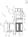
- a panel processing system in the form of a panel sizing saw carries in Figure 1 overall the reference numeral 10. It comprises a saw as a dividing device, which in Figure 1 however, is not shown. Only the dividing or sawing line is indicated by a dot-dash line with the reference symbol 12. Dividing devices with other cutting methods are also possible, for example a dividing device with a milling tool. Above the sawing line 12 there is a pressure bar 14 with a preferably automatic labeling system 15, for example with a preferably movable label printer.
- the panel sizing saw 10 specifically shown here also includes a support table 16 which is formed, for example, by a plurality of rollers (not shown). On the support table 16 are in Figure 1
- the illustrated initial configuration of the panel dividing saw 10 has several stacks of panel-shaped workpieces 18a, with FIG Figure 1 For reasons of illustration, a corresponding reference symbol is used only at one point.
- the workpieces 18a can be moved by a first feed device 20 in the feed direction (arrow 22) and also against the feed direction 22 by gripping the stack of plate-shaped workpieces 18a by first gripping devices 24, of which again only one is provided with a reference symbol for reasons of illustration .
- These gripping devices 24 are attached to a first carrier 26.
- the panel dividing saw 10 further comprises a second feed device 28 which is arranged laterally next to the first feed device 20.
- the second feed device 28 comprises a second carrier 30 on which a second gripping device 32 is attached laterally towards the support table 16.
- the two feed devices 20 and 28 together form a conveyor device 33.
- the second carrier 30 is, as will be explained in greater detail below, attached to the underside of a third carrier 34, which is extends parallel to the feed direction 22 and limits the support table 16 laterally.
- a fourth carrier 36 is present parallel to the third carrier 34 on the other side of the support table 16.
- the first carrier 26 is mounted in the manner of a portal on the upper sides of the third carrier 34 and the fourth carrier 36, whereas the second carrier 30 is mounted in the manner of a slide on the underside of the third carrier 34.
- a feed area 38 is defined transversely to the feed direction 22 by the support table 16 and the two carriers 34 and 36, in which the workpieces 18a to be moved by the feed devices 20 and 28 can be arranged.
- the feed area 38 again has a first width area 40 and a second width area 42 transversely to the feed direction 22, which in FIG Figure 1 are marked by corresponding arrows in width.
- the first width area 40 is defined in that the first gripping devices 24 are arranged in it
- the second width area 42 is defined in that the second gripping device 32 is arranged in it.
- the panel-dividing saw 10 shown has, on the side of the saw line 12 or of the pressure beam 14 facing away from the support table 16, a removal table 44 consisting of several individual tables. Again for reasons of illustration, only one of the individual tables is provided with a reference number. As will be explained in more detail below, the workpieces 18b divided by the saw can be removed from this removal table 44 by an operator 45 of the panel dividing saw 10 or fed back to the first feed device 20 and / or the second feed device 28 for further division .
- the panel dividing saw 10 specifically shown here has in the area of the support table 16 a turntable (not shown) as well as alignment stops (also not shown), among others on the Pressure bars 14, which can be moved from a lowered rest position to a raised working position and back.
- a buffer table 46 with a labeling system 48 for example with a label printer.
- a labeling system 48 for example with a label printer.
- an angular ruler 50 which extends parallel to the feed direction 22 and which is fixedly connected to the removal table 44.
- a top side 52 of the buffer table 46 is always flush with a top side 54 of the removal table 44.
- the buffer table 46 is offset relative to the removal table 44 so that the angle ruler 50 does not prevent the transport of the divided workpiece 18b.
- the buffer table 46 At its edge remote from the removal table 44, the buffer table 46 has a stop in the form of a vertically standing board-like bar, which is not shown, however.
- a roller bar instead of or in addition to the bar, a spray bar or a plurality of roller bars could be arranged.
- both the removal table 44 and the buffer table 46 and also the angle ruler 50 are or can be designed as so-called "air cushion tables". These have on their upper side a large number of air nozzles that can be closed, for example, by a ball valve. If a workpiece lies on such an air nozzle, the ball of the ball valve is pressed downwards by the weight of the workpiece so that air can flow out of the air nozzle and form an air cushion between the buffer table 46 or removal table 44 and the workpiece. By changing the air flow, the friction between the removal table 44 and the workpieces 18b and thus the speed of the workpieces 18b on the air cushion can be controlled or regulated manually or automatically.
- the panel-dividing system 10 shown only schematically, is a so-called "angular system", which consists of two individual dividing systems arranged one after the other at an angle of 90 ° to one another and in the material flow 10a and 10b, each similar to that in Figure 1 Panel dividing system 10 shown in greater detail are constructed. It will be in Figure 3 for functionally equivalent components, elements and areas the same reference numerals as in Figure 1 used, with fewer parts of the merely schematic representation being drawn.
- the reference symbols of the individual dividing system 10a are provided with the index “a”, those of the individual dividing system 10b are provided with the index “b”.
- a longitudinal division is carried out with the individual dividing system 10a, and a transverse division is carried out with the individual dividing system 10b.
- the two individual dividing systems 10a and 10b are connected to one another in a transverse transfer area 72.
- An aligning device 74 is arranged in this, which aligns the plate packs coming from the individual panel dividing system 10a before they are transported away by the individual panel dividing system 10b.
- the panel dividing saw 10 can normally work, for example, as follows: First, a comparatively large panel-shaped workpiece 18a is fed to the saw by the first feed device 20 and divided into several elongated, strip-like workpieces. This is known as a "longitudinal split". The divided strip-like workpieces are then rotated by 90 ° on the removal table 44 by an operator 45 who is standing in the area of the removal table 44 and brought into contact with the angle ruler 50.
- the two strip-shaped workpieces are pushed by the operator 45 over the sawing line 12 in the direction of the two feed devices 20 and 28 in order to be gripped by them.
- the second feed device 28 should grip the workpiece adjacent to the angular ruler 50 and the first feed device 20 should grip the other strip-shaped workpiece.
- both strip-shaped workpieces are divided transversely. This is known as "cross-division". Since the workpieces, an automated process controlled by a control and regulating device, not shown, is set in motion in which the Both feed devices 20 and 28 pull the two strip-shaped workpieces from the removal table 44 completely against the feed direction 22 over the saw line 12 onto the support table 16. There the two workpieces are brought into contact with a lateral angle ruler (not shown) present there in the area of the third carrier 34 and then fed to the saw in the feed direction 22. This feed takes place by the first feed device 20 independently of the second feed device 28, so that a different cutting pattern can be realized on one strip-shaped workpiece than on the other strip-shaped workpiece. This sectional image is realized by corresponding saw cuts along the saw line 12.
- the operator 45 can remove divided workpieces 18b, which are on the buffer table 46 and originate from a previous sawing process, from the buffer table 46 and stack them, for example, on stacking stations 56.
- the removal tables 44, the angle ruler 50, the buffer table 46 and the stacking stations 56 are all part of a handling area 58.
- various small individual workpieces 18b are now produced, which are pushed onto the removal table 44 by the feed devices 20 and 28.
- the individual workpieces 18b have a label, whereby the labeling can take place automatically before the division (by means of surface labeling, not shown) and / or during the division (by means of the automatic label printer 15) or manually after the division (by means of the label printer 48).
- a part of the workpieces 18b that arrive on the removal table 44 in this way is removed directly from the removal table 44 by the operator 45 and distributed to the stacking stations 56.
- the amount of finished workpieces 18b arriving on the removal table 44 during a unit of time is greater than the amount that the operator 45 can distribute to the destacking stations 56 during this unit of time, the operator 45 pushes them Workpieces 18b, which cannot be distributed to the stacking stations 56 in the available time unit, on the buffer table 46.
- the removal table 44 is free of divided workpieces 18b, whereas workpieces may remain on the buffer table 46.
- the method described above works not only with individual workpieces 18, but also with packages of workpieces, that is to say several workpieces lying on top of one another.
- the division process can be automated even further if, as in the embodiment of Figure 2 , two individual dividing systems 10a and 10b are connected to one another via a cross transfer area 74.
- a longitudinal division is carried out by a single dividing system 10a.
- the strip-shaped workpieces 18a divided on the individual dividing system 10a (“longitudinal saw") are transported by means of the transverse transfer area 72, aligned by the alignment device 74 and then divided in the individual dividing device 10b ("cross saw").
- the panel sizing saw 10 also includes a first detection device 61 comprising two cameras 60, which are arranged above the handling area 58, i.e. from the removal table 44 and from the buffer table 46 and from the stacking stations 56, as well as above the feed area 38.
- the field of view of the cameras 60 is on the feed table 16, the removal table 44, the buffer table 46, and the stacking stations 56 and thus not only on a partial area of the panel sizing saw 10, but basically aimed at the entire panel dividing saw 10 and the area surrounding it.
- the cameras 60 can also be arranged at other locations on the panel dividing saw 10, for example at the side, front, rear, below, on the pressure beam 14, the feed devices 20 and / or 28, or at several of these locations.
- the panel sizing saw 10 also includes a laser projector (not shown) that can project information or instructions to the operator 45 onto workpieces 18b that are on the removal table 44, the buffer table 46 or the stacking stations 56, as well as at any other point on the panel sizing saw 10 can, which can be viewed by an operator 45.
- a laser projector instead of the laser projector or in addition to the laser projector, a beamer or another device can also be used to project information. In order to avoid the risk of shadowing, several such devices can be used in different places.
- the operator 45 can wear a headset consisting of headphones and a microphone, which can be used for voice output to the operator 45 and by the operator 45 for voice input.
- a keyboard 62 is provided for the tactile input of commands, and a screen 64 with a drive (not shown) for changing the orientation and position of the screen 64 is provided to display information.
- the cameras 60 of the first acquisition device 61 acquire images.
- the first detection device 61 also includes a contactless locating system 76 (eg using RFID), which in the present case comprises several receivers 78, only one of which is symbolically represented, on the panel dividing system 10 and transponder 80 at the operator 45.
- the presence and identity of the operator 45 can also be detected and recognized by means of the positioning system 76, so that corresponding signals are sent to a control and Control device 66 can be forwarded.
- Corresponding authorizations for machine operation and / or for troubleshooting can be released in accordance with the established identity of operator 45, and certain operator-specific settings can be made automatically.
- the first detection device 61 can for example have cameras 60 with an integrated or downstream image recognition and image evaluation function.
- the panel sizing saw 10 comprises a control and regulating device 66 which receives information from numerous detection devices, for example from the cameras 60, the positioning and identity system 76, the keyboard 62 and the microphone, as well as from a large number of sensors, for example limit switches of the panel dividing saw 10.
- the control and regulating device 66 has a memory in which a computer program is stored, with which a method for operating the panel dividing saw 10 can be controlled.
- the control and regulating device 66 has an image processing and evaluation device, which also belongs to the first detection device 61 described above. Based on the signals provided by the cameras 60, this determines variables which include: the presence of safety-relevant components; Damage to safety-relevant components and / or workpieces; Presence and position of components relevant to the material flow; Damage to components relevant to the material flow; Presence, identity, size, position in a transport and / or handling area of a workpiece; Operating noise of the plate processing system.
- the panel dividing saw 10 further comprises a second detection device which is different from the first detection device 61 in terms of the functional principle, which is shown in FIG Figure 1 is only shown schematically by a circle with the reference numeral 70.
- the second detection device 70 detects the states of the panel dividing saw 10, for example by means of information supplied by position sensors, limit switches, displacement sensors, power measuring devices, etc., and supplies corresponding signals to the control and regulating device 66.
- the control and regulating device 66 determines a situation that is selected from a group of predefined situations.
- the group can include, for example, the following predefined situations: (e) A safety device of the panel sizing saw 10 missing or defective. (f) The panel sizing saw 10 is defective.
- the feed area 38 and the handling area 58 of the panel sizing saw 10 are monitored independently by the first detection device 61.
- the control and regulating device 66 selects or defines a situation which, taking into account the determined variable (s), is present with the greatest probability in or near the panel dividing saw 10. Depending on the situation, the control and regulating device 66 then decides whether the defined situation justifies an action or even makes it necessary, and, if so, which action should take place. It is possible, for example, for a specific action or a plurality or sequence of specific actions to be permanently assigned to each situation.
- Actions may include: (a) starting operation of panel sizing saw 10; (b) accelerating the operation of panel sizing saw 10; (c) slow down the operation of the Panel dividing saw 10; (d) stopping the operation of the panel dividing saw 10; (e) Output of warning information, for example via a loudspeaker or the above-mentioned projector; (f) output of an alarm, for example in the form of an acoustic warning signal or a flashing light or a display on the screen 64; (g) adapting a geometry of the panel sizing saw 10, for example adapting the working height of the removal tables 44 and / or the buffer table 46 to the size of the identified operator; (i) Issuing an instruction to the operator 45, for example for aligning a workpiece 18; (j) Adaptation of a program sequence, for example disposal of a damaged workpiece and subsequent production of the disposed workpiece.
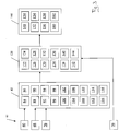
- the control and regulating device 66 determines the presence (block 84), the identity (block 86), the current position (block 88), the current speed of movement (block 90), the current direction of movement (block 92), the current movement pattern (block 94), the current acceleration (block 96) and the current noise (block 98) of the operator 45 , the presence (block 100), the identity (block 102), the current position (block 104), the current speed of movement (block 106), the current direction of movement (block 108), the current acceleration (block 110) and the current size (Block 112) of the workpiece 18 and the determined variables with stored comparison variables for certain operating situations defined as normal and certain Be defined as abnormal drive situations compared.
- the degree of processing can also be a Cutting plan are recorded or the identity of a damaged workpiece 18.
- an image comparison is used to determine whether certain safety-relevant components of the panel sizing saw 10 are present or missing (block 114) or whether certain safety-relevant components of the panel sizing saw 10 are damaged (block 116).
- the current operating noise of the panel sizing saw 10 is also recorded and compared with previously stored noise patterns that occur in normal operation and in certain operating states subject to malfunctions (block 118).
- All of the named sizes 74-118 are sizes that are relevant for the safety of a person located in the handling area 58 and / or the safe operation of the panel sizing saw 10.
- a comparison of an individual variable with a corresponding comparative variable can already be sufficient to infer the existence of a certain situation with a sufficient degree of probability (block 120).
- several values are compared with the corresponding comparison values.
- the results of the comparisons can then be weighted, for example, and probabilities for the existence of certain situations can be calculated from this. The situation with the highest probability is then selected in the subsequent block 120.
- the existence of a specific situation is then inferred from the determined variables and the comparison carried out, a predefined and stored list of possible situations being used here as an example.
- the panel sizing saw 10 is defective or is about to become defective (block 132). There is no person present (block 134).
- the workpiece 18 in the feed or transport area 38 or in the handling area 58 is in the specified target position and there are no disruptions in the flow of material (block 136).
- There is a collision situation for example a workpiece has an incorrect position or incorrect position in the transport area 38 (block 138).
- the detected workpiece 18 is damaged and must be taken care of and re-produced (block 142).
- a prerequisite for the continuation of the interrupted program sequence does not exist: a workpiece 18 and / or material flow-relevant assemblies of the panel dividing system 10 are not in the specified target position (block 144).
- the signals from second detection device 70 are used to check whether one of the above-mentioned situations actually exists.
- a defective feed device 20 may have been inferred from the cameras 60 (block 132), but the corresponding limit switches of the second detection device 70 assigned to the first feed device 20 do not confirm this.
- a query can be output to the operator via the screen 64, asking for a review of the situation.
- an action is then triggered depending on the determined situation. Again, possible actions are selected from a predefined list. If, for example, the above “normal situation” 122 is determined, the operation of the panel dividing saw can be started (“starting up the system”, block 148). If the presence of the situation 122 is also determined, the operation of the dividing saw 10 can be accelerated (block 150). If it is determined that a person is in a restricted area (situation 126), the operation the panel dividing saw 10 is slowed down (block 152) and warning information is output (block 154).
- the operation of the panel sizing saw 10 is stopped immediately ("stopping the system", block 156) and an alarm is triggered if necessary (block 158). If the situation is that a safety device of the panel sizing saw 10 is missing or defective (situation 130), warning information is also output (block 154) and, if necessary, the operation of the panel sizing system 10 is made impossible or stopped (block 156). If the panel sizing saw 10 is defective or is about to become defective, or if, for example, a workpiece is jammed somewhere (situation 132), the operation of the panel sizing saw 10 is also stopped (block 156) and a warning or error correction message or other instruction is issued the operator (block 154).
- the operator 45 can be instructed to bring a specific workpiece 18 in the panel dividing system 10 into a specific position and / or orientation.
- the height of the removal table 44 can also simply be adapted (block 160).
- the panel dividing system can be operated again (block 122) and it will determined and the cutting plan modified so that discarded workpieces 18 are reproduced (block 162).
Landscapes
- Engineering & Computer Science (AREA)
- Mechanical Engineering (AREA)
- Life Sciences & Earth Sciences (AREA)
- General Engineering & Computer Science (AREA)
- Physics & Mathematics (AREA)
- Optics & Photonics (AREA)
- Wood Science & Technology (AREA)
- Forests & Forestry (AREA)
- Radar, Positioning & Navigation (AREA)
- Remote Sensing (AREA)
- Sawing (AREA)
Claims (6)
- Procédé pour faire fonctionner une installation d'usinage de panneaux (10), selon lequel une zone d'observation (38, 58) de l'installation d'usinage de panneaux (10) est observée au moyen d'au moins un premier dispositif de détection (61), dans lequel• le premier dispositif de détection (61) détecte et reconnaît des images et/ou détecte des bruits;• une grandeur, qui est essentielle au fonctionnement en toute sécurité de l'installation d'usinage de panneaux (10), est déterminée (82) au moyen du premier dispositif de détection (61),• la présence d'une situation essentielle à la sécurité et la fiabilité pendant le fonctionnement de l'installation d'usinage de panneaux (10) est déduite (120) de la grandeur déterminée au moyen d'un dispositif d'évaluation (66), et• en fonction de la situation du dispositif d'évaluation (66), il est décidé si une action s'effectue (146) et, si oui, quelle action s'effectue,• dans lequel la grandeur qui est essentielle au fonctionnement en toute sécurité de l'installation d'usinage de panneaux (10) et est déterminée au moyen du premier dispositif de détection (61) est au moins une du groupe suivant:- la présence (114) d'éléments essentiels à la sécurité;- des détériorations (116) sur des éléments essentiels à la sécurité;- la présence et la position d'éléments essentiels au flux de matière;- des détériorations sur des éléments essentiels au flux de matière;- l'identité (102), la grandeur (112), la position (104) dans une zone de transport et/ou de manipulation, d'une pièce (18);- un bruit de fonctionnement (118) de l'installation d'usinage de panneaux (10).
- Procédé selon l'une quelconque des revendications précédentes, caractérisé en ce que l'action est au moins une du groupe suivant: le démarrage (148) de l'installation (10); l'accélération (150) de l'installation (10); le ralentissement (152) de l'installation (10); l'arrêt (156) de l'installation (10); la délivrance (154) d'une information d'avertissement ou de suppression des défaillances ou une autre instruction, par exemple pour orienter une pièce, à l'opérateur (45); l'émission (158) d'une alarme; l'adaptation (160) d'une géométrie de machine; l'adaptation (162) d'un déroulement de programme, par exemple l'élimination d'une pièce détériorée et la nouvelle production de la pièce éliminée.
- Procédé selon l'une quelconque des revendications précédentes, caractérisé en ce que la présence de la situation est vérifiée à l'aide d'au moins un deuxième dispositif de détection (70, 76) et différent du premier dispositif de détection du point de vue du principe de fonctionnement.
- Procédé selon la revendication 3, caractérisé en ce que le deuxième dispositif de détection (70) détecte des états de machine.
- Procédé selon l'une quelconque des revendications précédentes, caractérisé en ce que la situation est sélectionnée dans un groupe de situations prédéfinies, dans lequel le groupe comprend au moins:le dispositif de sécurité est absent ou endommagé (130);l'installation d'usinage de panneaux est défectueuse (132); une pièce (18) se trouve dans une zone de transport (38) ou dans une zone de manipulation (58) dans une position théorique et aucune perturbation du flux de matière n'est présente (136); une situation de collision est présente (138); un objet gênant se trouve dans la zone de transport (140); une pièce (18) détectée est détériorée et nécessite d'être éliminée et à nouveau produite (142); une condition requise pour une poursuite d'un déroulement de programme interrompu est présente ou n'est pas présente (144).
- Installation d'usinage de panneaux (10), avec au moins un premier dispositif de détection (61) pour observer une zone d'observation (38, 58) de l'installation d'usinage de panneaux (10), caractérisée en ce qu'elle présente un dispositif de commande et/ou de réglage (66), qui est programmé pour exécuter un procédé selon l'une quelconque des revendications précédentes.
Applications Claiming Priority (2)
| Application Number | Priority Date | Filing Date | Title |
|---|---|---|---|
| DE102014210612.5A DE102014210612A1 (de) | 2014-06-04 | 2014-06-04 | Verfahren zum Betreiben einerPlattenbearbeitungsanlage, sowiePlattenbearbeitungsanlage |
| PCT/EP2015/060932 WO2015185351A1 (fr) | 2014-06-04 | 2015-05-19 | Procédé permettant de faire fonctionner une installation d'usinage de panneaux, et installation d'usinage de panneaux |
Publications (2)
| Publication Number | Publication Date |
|---|---|
| EP3152017A1 EP3152017A1 (fr) | 2017-04-12 |
| EP3152017B1 true EP3152017B1 (fr) | 2020-10-07 |
Family
ID=53274510
Family Applications (1)
| Application Number | Title | Priority Date | Filing Date |
|---|---|---|---|
| EP15725550.6A Active EP3152017B1 (fr) | 2014-06-04 | 2015-05-19 | Procédé permettant de faire fonctionner une installation d'usinage de panneaux, et installation d'usinage de panneaux |
Country Status (4)
| Country | Link |
|---|---|
| EP (1) | EP3152017B1 (fr) |
| CN (1) | CN106470797B (fr) |
| DE (1) | DE102014210612A1 (fr) |
| WO (1) | WO2015185351A1 (fr) |
Families Citing this family (14)
| Publication number | Priority date | Publication date | Assignee | Title |
|---|---|---|---|---|
| DE102016104663A1 (de) * | 2016-03-14 | 2017-09-14 | Holzma Plattenaufteiltechnik Gmbh | Plattenbearbeitungsanlage sowie Verfahren zum Aufteilen von mindestens einem Werkstück mit einer Plattenbearbeitungsanlage |
| CN107962456B (zh) * | 2016-10-19 | 2019-11-12 | 电子科技大学中山学院 | 一种新型数控机床多电机轴线对齐检测装置 |
| DE102017113788A1 (de) * | 2017-06-21 | 2018-12-27 | Holz-Her Gmbh | Sägevorrichtung |
| DE102017007605A1 (de) * | 2017-08-10 | 2019-02-14 | Michael Weinig Ag | Verfahren zum Auftrennen länglicher Werkstücke sowie Bearbeitungsmaschine zur Durchführung eines solchen Verfahrens |
| DE102017121956A1 (de) * | 2017-09-21 | 2019-03-21 | Homag Plattenaufteiltechnik Gmbh | Verfahren zum Bearbeiten von Werkstücken, Computerprogrammprodukt, sowie Werkstückbearbeitungsanlage |
| EP3488984A1 (fr) * | 2017-11-24 | 2019-05-29 | SCM Group S.p.A. | Machine pour l'usinage de pièces faites de bois ou equivalent et equipees d'un systeme de detection de presence d'un operateur, et methode d'utilisation |
| EP4245448A3 (fr) * | 2018-10-05 | 2023-11-22 | IMA Schelling Austria GmbH | Installation de division de plaques |
| CN111553179B (zh) * | 2019-02-12 | 2023-05-05 | 阿里巴巴集团控股有限公司 | 服装质检状态、动作状态确定方法和装置以及电子设备 |
| DE102019130154B4 (de) * | 2019-11-08 | 2023-12-21 | TRUMPF Werkzeugmaschinen SE + Co. KG | Verfahren zum visuellen Unterstützen eines Handhabungsvorgangs und Flachbettwerkzeugmaschine |
| IT201900021108A1 (it) * | 2019-11-13 | 2021-05-13 | Gamma System S R L | Sistema di sicurezza per un macchinario industriale |
| CN114986632A (zh) * | 2021-03-01 | 2022-09-02 | 楠镕电机有限公司 | 加工机的人体界定的安全辨识系统 |
| IT202100027398A1 (it) * | 2021-10-26 | 2023-04-26 | Scm Group Spa | Centro di lavoro perfezionato e metodo di funzionamento relativo. |
| CN114986621B (zh) * | 2022-05-07 | 2023-02-24 | 深圳市雨滴科技有限公司 | 一种板材自动切割机及其切割方法 |
| EP4338909A1 (fr) * | 2022-09-15 | 2024-03-20 | SCM Group S.p.A. | Méthode améliorée de découpage d'un panneau et système de découpage correspondant |
Citations (2)
| Publication number | Priority date | Publication date | Assignee | Title |
|---|---|---|---|---|
| US20070085502A1 (en) * | 2005-10-13 | 2007-04-19 | Cargill, Incorporated | Braking system and method |
| WO2013135608A1 (fr) * | 2012-03-16 | 2013-09-19 | Pilz Gmbh & Co. Kg | Procédé et dispositif destinés sécuriser une zone de travail dangereuse d'une machine à fonctionnement automatique. |
Family Cites Families (16)
| Publication number | Priority date | Publication date | Assignee | Title |
|---|---|---|---|---|
| ITMI20011046A1 (it) * | 2001-05-18 | 2002-11-18 | C M L S R L | Impianto atto a rilevare le irregolarita' dimensionali di tavole ottenute mediante sezionamento di tronchi allo scopo di memorizzare e di ot |
| JP4186663B2 (ja) * | 2003-03-20 | 2008-11-26 | 日立工機株式会社 | 卓上丸鋸 |
| US7163038B2 (en) * | 2004-03-01 | 2007-01-16 | Globe Machine Manufacturing Company | Systems and methods for end squaring and dividing elongated materials |
| DE102004043514A1 (de) * | 2004-09-08 | 2006-03-09 | Sick Ag | Verfahren und Vorrichtung zum Steuern einer sicherheitsrelevanten Funktion einer Maschine |
| CN101511531A (zh) * | 2006-09-04 | 2009-08-19 | 罗伯特·博世有限公司 | 机床监测装置 |
| DE102007041097A1 (de) * | 2006-09-04 | 2008-03-06 | Robert Bosch Gmbh | Werkzeugmaschinenüberwachungsvorrichtung |
| DE102006052017B4 (de) * | 2006-11-03 | 2009-03-05 | Homag Holzbearbeitungssysteme Ag | Bearbeitungsmaschine |
| DE102008014869A1 (de) | 2008-03-18 | 2009-09-24 | Holzma Plattenaufteiltechnik Gmbh | Verfahren zum Betreiben einer Plattenaufteilanlage |
| CN102099614A (zh) * | 2008-06-26 | 2011-06-15 | Abb股份公司 | 防备机器人危险事件的人安全保护系统 |
| DE102008032160B9 (de) * | 2008-07-08 | 2010-09-23 | Holzma Plattenaufteiltechnik Gmbh | Verfahren zum Aufteilen plattenförmiger Werkstücke, sowie Plattenaufteilanlage |
| DE102008034050A1 (de) | 2008-07-22 | 2010-01-28 | Holzma Plattenaufteiltechnik Gmbh | Verfahren zum Aufteilen großformatiger plattenförmiger Werkstücke, sowie Plattenaufteilanlage |
| CN101825780B (zh) * | 2009-03-05 | 2011-08-24 | 北京京东方光电科技有限公司 | 液晶面板周边残材检出和去除的装置及其方法 |
| DE202009007035U1 (de) * | 2009-05-15 | 2010-10-14 | Homag Holzbearbeitungssysteme Ag | Bearbeitungsmaschine mit Sicherheitsscanner |
| DE102009038120A1 (de) | 2009-08-17 | 2011-02-24 | Holzma Plattenaufteiltechnik Gmbh | Plattenaufteilanlage |
| DE102010017857B4 (de) | 2010-04-22 | 2019-08-08 | Sick Ag | 3D-Sicherheitsvorrichtung und Verfahren zur Absicherung und Bedienung mindestens einer Maschine |
| CN201736304U (zh) * | 2010-07-21 | 2011-02-09 | 湖州世友世家木业有限公司 | 一种复合地板切割机 |
-
2014
- 2014-06-04 DE DE102014210612.5A patent/DE102014210612A1/de not_active Ceased
-
2015
- 2015-05-19 WO PCT/EP2015/060932 patent/WO2015185351A1/fr active Application Filing
- 2015-05-19 CN CN201580033688.6A patent/CN106470797B/zh active Active
- 2015-05-19 EP EP15725550.6A patent/EP3152017B1/fr active Active
Patent Citations (2)
| Publication number | Priority date | Publication date | Assignee | Title |
|---|---|---|---|---|
| US20070085502A1 (en) * | 2005-10-13 | 2007-04-19 | Cargill, Incorporated | Braking system and method |
| WO2013135608A1 (fr) * | 2012-03-16 | 2013-09-19 | Pilz Gmbh & Co. Kg | Procédé et dispositif destinés sécuriser une zone de travail dangereuse d'une machine à fonctionnement automatique. |
Also Published As
| Publication number | Publication date |
|---|---|
| DE102014210612A1 (de) | 2015-12-17 |
| EP3152017A1 (fr) | 2017-04-12 |
| CN106470797B (zh) | 2020-10-13 |
| CN106470797A (zh) | 2017-03-01 |
| WO2015185351A1 (fr) | 2015-12-10 |
Similar Documents
| Publication | Publication Date | Title |
|---|---|---|
| EP3152017B1 (fr) | Procédé permettant de faire fonctionner une installation d'usinage de panneaux, et installation d'usinage de panneaux | |
| WO2015135686A1 (fr) | Procédé servant à faire fonctionner une installation d'usinage de panneaux | |
| EP1561066B1 (fr) | Dispositif de securite pour machine, en particulier pour une presse a plier | |
| EP3104998B1 (fr) | Procédé pour opérer un dispositif de découpe de plaques, et dispositif de découpe de plaques pour la mise en oeuvre d'un tel procédé | |
| EP2253417B1 (fr) | Machine de traitement dotée d'un scanner de sécurité | |
| DE19653953A1 (de) | Verfahren und Vorrichtung zum Entpalettieren von Artikeln | |
| DE102008021671A1 (de) | Verfahren und Vorrichtung zur Überwachung eines Manipulators | |
| EP3427111B1 (fr) | Procédé de fonctionnement d'une machine de chaîne de production ainsi que machine de chaîne de production | |
| DE102004058472A1 (de) | Sicherheitseinrichtung und Verfahren zum Bestimmen eines Nachlaufweges bei einer Maschine | |
| EP2644962A1 (fr) | Dispositif de déformation et procédé de fonctionnement dýun dispositif de déformation | |
| DE10143505A1 (de) | Sicherungsverfahren und optoelektronischer Sensor | |
| EP1599693B1 (fr) | Procede de securite et detecteur opto-electronique | |
| AT520726B1 (de) | Verfahren zur Überwachung einer Fertigungsanlage sowie Fertigungsanlage mit einem Sicherheitssystem | |
| EP3037227B1 (fr) | Procédé et dispositif d'usinage de pièces en forme de plaques | |
| WO2017089205A1 (fr) | Procédé d'usinage d'une pièce de forme plate, et installation de division de plaques destinée à la mise en oeuvre du procédé | |
| EP2660019B1 (fr) | Installation de traitement de produits empilés en forme de feuilles en utilisant une machine à découper | |
| EP2527067B1 (fr) | Dispositif de séparation pour le sciage d'au moins une pièce en forme de plaque ou de block. | |
| WO2004078626A1 (fr) | Dispositif de securite loge dans la console d'une machine de traitement de feuilles | |
| DE102010011786A1 (de) | Verfahren und Sicherheitsvorrichtung zur Steuerung und Absicherung einer Maschine | |
| EP3867560B1 (fr) | Procédé servant à adapter une fonction de protection pendant un fonctionnement d'une machine en générant une zone de fenêtre non surveillée avec des systèmes de protection sans séparation, et dispositif de protection | |
| DE202010009017U1 (de) | Vorrichtung zur Trennung von Befestigungsstellen, die zwei Ränder einer Schnittlinie in einem Kartonzuschnitt verbinden | |
| WO2021094444A1 (fr) | Machine à cintrer et procédé d'usinage d'une pièce à usiner au moyen d'une machine à cintrer | |
| DE202024101553U1 (de) | Holzverarbeitungsanlage | |
| DE102022100050A1 (de) | Vorrichtung zum Bearbeiten von, insbesondere plattenförmigen, Werkstücken aus Holz oder Holzersatzstoffen sowie Verfahren zum Betrieb einer solchen Vorrichtung | |
| EP1710648A2 (fr) | Dispositif et méthode de surveillance d'un procédé de fabrication |
Legal Events
| Date | Code | Title | Description |
|---|---|---|---|
| STAA | Information on the status of an ep patent application or granted ep patent |
Free format text: STATUS: THE INTERNATIONAL PUBLICATION HAS BEEN MADE |
|
| PUAI | Public reference made under article 153(3) epc to a published international application that has entered the european phase |
Free format text: ORIGINAL CODE: 0009012 |
|
| STAA | Information on the status of an ep patent application or granted ep patent |
Free format text: STATUS: REQUEST FOR EXAMINATION WAS MADE |
|
| 17P | Request for examination filed |
Effective date: 20161228 |
|
| AK | Designated contracting states |
Kind code of ref document: A1 Designated state(s): AL AT BE BG CH CY CZ DE DK EE ES FI FR GB GR HR HU IE IS IT LI LT LU LV MC MK MT NL NO PL PT RO RS SE SI SK SM TR |
|
| AX | Request for extension of the european patent |
Extension state: BA ME |
|
| DAV | Request for validation of the european patent (deleted) | ||
| DAX | Request for extension of the european patent (deleted) | ||
| STAA | Information on the status of an ep patent application or granted ep patent |
Free format text: STATUS: EXAMINATION IS IN PROGRESS |
|
| RAP1 | Party data changed (applicant data changed or rights of an application transferred) |
Owner name: HOMAG PLATTENAUFTEILTECHNIK GMBH |
|
| 17Q | First examination report despatched |
Effective date: 20180102 |
|
| REG | Reference to a national code |
Ref country code: DE Ref legal event code: R079 Ref document number: 502015013604 Country of ref document: DE Free format text: PREVIOUS MAIN CLASS: B27G0021000000 Ipc: B27M0001080000 |
|
| GRAP | Despatch of communication of intention to grant a patent |
Free format text: ORIGINAL CODE: EPIDOSNIGR1 |
|
| STAA | Information on the status of an ep patent application or granted ep patent |
Free format text: STATUS: GRANT OF PATENT IS INTENDED |
|
| RIC1 | Information provided on ipc code assigned before grant |
Ipc: B27G 21/00 20060101ALI20200325BHEP Ipc: B23Q 11/00 20060101ALI20200325BHEP Ipc: B27M 1/08 20060101AFI20200325BHEP Ipc: B23Q 17/24 20060101ALI20200325BHEP Ipc: F16P 3/14 20060101ALI20200325BHEP |
|
| INTG | Intention to grant announced |
Effective date: 20200421 |
|
| GRAS | Grant fee paid |
Free format text: ORIGINAL CODE: EPIDOSNIGR3 |
|
| GRAA | (expected) grant |
Free format text: ORIGINAL CODE: 0009210 |
|
| STAA | Information on the status of an ep patent application or granted ep patent |
Free format text: STATUS: THE PATENT HAS BEEN GRANTED |
|
| AK | Designated contracting states |
Kind code of ref document: B1 Designated state(s): AL AT BE BG CH CY CZ DE DK EE ES FI FR GB GR HR HU IE IS IT LI LT LU LV MC MK MT NL NO PL PT RO RS SE SI SK SM TR |
|
| REG | Reference to a national code |
Ref country code: GB Ref legal event code: FG4D Free format text: NOT ENGLISH |
|
| REG | Reference to a national code |
Ref country code: CH Ref legal event code: EP Ref country code: AT Ref legal event code: REF Ref document number: 1320650 Country of ref document: AT Kind code of ref document: T Effective date: 20201015 |
|
| REG | Reference to a national code |
Ref country code: IE Ref legal event code: FG4D Free format text: LANGUAGE OF EP DOCUMENT: GERMAN |
|
| REG | Reference to a national code |
Ref country code: DE Ref legal event code: R096 Ref document number: 502015013604 Country of ref document: DE |
|
| REG | Reference to a national code |
Ref country code: NL Ref legal event code: MP Effective date: 20201007 |
|
| PG25 | Lapsed in a contracting state [announced via postgrant information from national office to epo] |
Ref country code: GR Free format text: LAPSE BECAUSE OF FAILURE TO SUBMIT A TRANSLATION OF THE DESCRIPTION OR TO PAY THE FEE WITHIN THE PRESCRIBED TIME-LIMIT Effective date: 20210108 Ref country code: FI Free format text: LAPSE BECAUSE OF FAILURE TO SUBMIT A TRANSLATION OF THE DESCRIPTION OR TO PAY THE FEE WITHIN THE PRESCRIBED TIME-LIMIT Effective date: 20201007 Ref country code: RS Free format text: LAPSE BECAUSE OF FAILURE TO SUBMIT A TRANSLATION OF THE DESCRIPTION OR TO PAY THE FEE WITHIN THE PRESCRIBED TIME-LIMIT Effective date: 20201007 Ref country code: PT Free format text: LAPSE BECAUSE OF FAILURE TO SUBMIT A TRANSLATION OF THE DESCRIPTION OR TO PAY THE FEE WITHIN THE PRESCRIBED TIME-LIMIT Effective date: 20210208 Ref country code: NO Free format text: LAPSE BECAUSE OF FAILURE TO SUBMIT A TRANSLATION OF THE DESCRIPTION OR TO PAY THE FEE WITHIN THE PRESCRIBED TIME-LIMIT Effective date: 20210107 Ref country code: NL Free format text: LAPSE BECAUSE OF FAILURE TO SUBMIT A TRANSLATION OF THE DESCRIPTION OR TO PAY THE FEE WITHIN THE PRESCRIBED TIME-LIMIT Effective date: 20201007 |
|
| REG | Reference to a national code |
Ref country code: LT Ref legal event code: MG4D |
|
| PG25 | Lapsed in a contracting state [announced via postgrant information from national office to epo] |
Ref country code: ES Free format text: LAPSE BECAUSE OF FAILURE TO SUBMIT A TRANSLATION OF THE DESCRIPTION OR TO PAY THE FEE WITHIN THE PRESCRIBED TIME-LIMIT Effective date: 20201007 Ref country code: BG Free format text: LAPSE BECAUSE OF FAILURE TO SUBMIT A TRANSLATION OF THE DESCRIPTION OR TO PAY THE FEE WITHIN THE PRESCRIBED TIME-LIMIT Effective date: 20210107 Ref country code: IS Free format text: LAPSE BECAUSE OF FAILURE TO SUBMIT A TRANSLATION OF THE DESCRIPTION OR TO PAY THE FEE WITHIN THE PRESCRIBED TIME-LIMIT Effective date: 20210207 Ref country code: SE Free format text: LAPSE BECAUSE OF FAILURE TO SUBMIT A TRANSLATION OF THE DESCRIPTION OR TO PAY THE FEE WITHIN THE PRESCRIBED TIME-LIMIT Effective date: 20201007 Ref country code: PL Free format text: LAPSE BECAUSE OF FAILURE TO SUBMIT A TRANSLATION OF THE DESCRIPTION OR TO PAY THE FEE WITHIN THE PRESCRIBED TIME-LIMIT Effective date: 20201007 Ref country code: LV Free format text: LAPSE BECAUSE OF FAILURE TO SUBMIT A TRANSLATION OF THE DESCRIPTION OR TO PAY THE FEE WITHIN THE PRESCRIBED TIME-LIMIT Effective date: 20201007 |
|
| PG25 | Lapsed in a contracting state [announced via postgrant information from national office to epo] |
Ref country code: HR Free format text: LAPSE BECAUSE OF FAILURE TO SUBMIT A TRANSLATION OF THE DESCRIPTION OR TO PAY THE FEE WITHIN THE PRESCRIBED TIME-LIMIT Effective date: 20201007 |
|
| REG | Reference to a national code |
Ref country code: DE Ref legal event code: R097 Ref document number: 502015013604 Country of ref document: DE |
|
| PG25 | Lapsed in a contracting state [announced via postgrant information from national office to epo] |
Ref country code: LT Free format text: LAPSE BECAUSE OF FAILURE TO SUBMIT A TRANSLATION OF THE DESCRIPTION OR TO PAY THE FEE WITHIN THE PRESCRIBED TIME-LIMIT Effective date: 20201007 Ref country code: SK Free format text: LAPSE BECAUSE OF FAILURE TO SUBMIT A TRANSLATION OF THE DESCRIPTION OR TO PAY THE FEE WITHIN THE PRESCRIBED TIME-LIMIT Effective date: 20201007 Ref country code: RO Free format text: LAPSE BECAUSE OF FAILURE TO SUBMIT A TRANSLATION OF THE DESCRIPTION OR TO PAY THE FEE WITHIN THE PRESCRIBED TIME-LIMIT Effective date: 20201007 Ref country code: EE Free format text: LAPSE BECAUSE OF FAILURE TO SUBMIT A TRANSLATION OF THE DESCRIPTION OR TO PAY THE FEE WITHIN THE PRESCRIBED TIME-LIMIT Effective date: 20201007 Ref country code: CZ Free format text: LAPSE BECAUSE OF FAILURE TO SUBMIT A TRANSLATION OF THE DESCRIPTION OR TO PAY THE FEE WITHIN THE PRESCRIBED TIME-LIMIT Effective date: 20201007 Ref country code: SM Free format text: LAPSE BECAUSE OF FAILURE TO SUBMIT A TRANSLATION OF THE DESCRIPTION OR TO PAY THE FEE WITHIN THE PRESCRIBED TIME-LIMIT Effective date: 20201007 |
|
| PLBE | No opposition filed within time limit |
Free format text: ORIGINAL CODE: 0009261 |
|
| STAA | Information on the status of an ep patent application or granted ep patent |
Free format text: STATUS: NO OPPOSITION FILED WITHIN TIME LIMIT |
|
| PG25 | Lapsed in a contracting state [announced via postgrant information from national office to epo] |
Ref country code: DK Free format text: LAPSE BECAUSE OF FAILURE TO SUBMIT A TRANSLATION OF THE DESCRIPTION OR TO PAY THE FEE WITHIN THE PRESCRIBED TIME-LIMIT Effective date: 20201007 |
|
| 26N | No opposition filed |
Effective date: 20210708 |
|
| PG25 | Lapsed in a contracting state [announced via postgrant information from national office to epo] |
Ref country code: AL Free format text: LAPSE BECAUSE OF FAILURE TO SUBMIT A TRANSLATION OF THE DESCRIPTION OR TO PAY THE FEE WITHIN THE PRESCRIBED TIME-LIMIT Effective date: 20201007 |
|
| PG25 | Lapsed in a contracting state [announced via postgrant information from national office to epo] |
Ref country code: SI Free format text: LAPSE BECAUSE OF FAILURE TO SUBMIT A TRANSLATION OF THE DESCRIPTION OR TO PAY THE FEE WITHIN THE PRESCRIBED TIME-LIMIT Effective date: 20201007 |
|
| REG | Reference to a national code |
Ref country code: CH Ref legal event code: PL |
|
| GBPC | Gb: european patent ceased through non-payment of renewal fee |
Effective date: 20210519 |
|
| PG25 | Lapsed in a contracting state [announced via postgrant information from national office to epo] |
Ref country code: CH Free format text: LAPSE BECAUSE OF NON-PAYMENT OF DUE FEES Effective date: 20210531 Ref country code: MC Free format text: LAPSE BECAUSE OF FAILURE TO SUBMIT A TRANSLATION OF THE DESCRIPTION OR TO PAY THE FEE WITHIN THE PRESCRIBED TIME-LIMIT Effective date: 20201007 Ref country code: LU Free format text: LAPSE BECAUSE OF NON-PAYMENT OF DUE FEES Effective date: 20210519 Ref country code: LI Free format text: LAPSE BECAUSE OF NON-PAYMENT OF DUE FEES Effective date: 20210531 |
|
| REG | Reference to a national code |
Ref country code: BE Ref legal event code: MM Effective date: 20210531 |
|
| PG25 | Lapsed in a contracting state [announced via postgrant information from national office to epo] |
Ref country code: IE Free format text: LAPSE BECAUSE OF NON-PAYMENT OF DUE FEES Effective date: 20210519 Ref country code: GB Free format text: LAPSE BECAUSE OF NON-PAYMENT OF DUE FEES Effective date: 20210519 |
|
| PG25 | Lapsed in a contracting state [announced via postgrant information from national office to epo] |
Ref country code: IS Free format text: LAPSE BECAUSE OF FAILURE TO SUBMIT A TRANSLATION OF THE DESCRIPTION OR TO PAY THE FEE WITHIN THE PRESCRIBED TIME-LIMIT Effective date: 20210207 Ref country code: FR Free format text: LAPSE BECAUSE OF NON-PAYMENT OF DUE FEES Effective date: 20210531 |
|
| PG25 | Lapsed in a contracting state [announced via postgrant information from national office to epo] |
Ref country code: BE Free format text: LAPSE BECAUSE OF NON-PAYMENT OF DUE FEES Effective date: 20210531 |
|
| PG25 | Lapsed in a contracting state [announced via postgrant information from national office to epo] |
Ref country code: HU Free format text: LAPSE BECAUSE OF FAILURE TO SUBMIT A TRANSLATION OF THE DESCRIPTION OR TO PAY THE FEE WITHIN THE PRESCRIBED TIME-LIMIT; INVALID AB INITIO Effective date: 20150519 |
|
| PG25 | Lapsed in a contracting state [announced via postgrant information from national office to epo] |
Ref country code: CY Free format text: LAPSE BECAUSE OF FAILURE TO SUBMIT A TRANSLATION OF THE DESCRIPTION OR TO PAY THE FEE WITHIN THE PRESCRIBED TIME-LIMIT Effective date: 20201007 |
|
| P01 | Opt-out of the competence of the unified patent court (upc) registered |
Effective date: 20230529 |
|
| PGFP | Annual fee paid to national office [announced via postgrant information from national office to epo] |
Ref country code: IT Payment date: 20230531 Year of fee payment: 9 |
|
| PGFP | Annual fee paid to national office [announced via postgrant information from national office to epo] |
Ref country code: AT Payment date: 20230516 Year of fee payment: 9 |
|
| PGFP | Annual fee paid to national office [announced via postgrant information from national office to epo] |
Ref country code: DE Payment date: 20230724 Year of fee payment: 9 |
|
| PG25 | Lapsed in a contracting state [announced via postgrant information from national office to epo] |
Ref country code: MK Free format text: LAPSE BECAUSE OF FAILURE TO SUBMIT A TRANSLATION OF THE DESCRIPTION OR TO PAY THE FEE WITHIN THE PRESCRIBED TIME-LIMIT Effective date: 20201007 |