EP3151606B1 - Positionnement d'emplacement pour têtes radio distantes (trd) ayant la même identité de cellule physique (pci) - Google Patents
Positionnement d'emplacement pour têtes radio distantes (trd) ayant la même identité de cellule physique (pci) Download PDFInfo
- Publication number
- EP3151606B1 EP3151606B1 EP16199799.4A EP16199799A EP3151606B1 EP 3151606 B1 EP3151606 B1 EP 3151606B1 EP 16199799 A EP16199799 A EP 16199799A EP 3151606 B1 EP3151606 B1 EP 3151606B1
- Authority
- EP
- European Patent Office
- Prior art keywords
- enodeb
- remote radio
- reference signal
- enodebs
- prs
- Prior art date
- Legal status (The legal status is an assumption and is not a legal conclusion. Google has not performed a legal analysis and makes no representation as to the accuracy of the status listed.)
- Active
Links
- 230000005540 biological transmission Effects 0.000 claims description 67
- 238000000034 method Methods 0.000 claims description 42
- 238000004891 communication Methods 0.000 claims description 34
- 238000004590 computer program Methods 0.000 claims description 9
- 230000011664 signaling Effects 0.000 claims description 6
- 230000015654 memory Effects 0.000 description 21
- 230000006870 function Effects 0.000 description 15
- 238000012545 processing Methods 0.000 description 15
- 238000005259 measurement Methods 0.000 description 14
- 238000010586 diagram Methods 0.000 description 13
- 238000005516 engineering process Methods 0.000 description 11
- 238000013461 design Methods 0.000 description 7
- 238000007726 management method Methods 0.000 description 7
- 230000008569 process Effects 0.000 description 7
- 238000000638 solvent extraction Methods 0.000 description 7
- 230000008901 benefit Effects 0.000 description 6
- 230000001360 synchronised effect Effects 0.000 description 6
- 230000003044 adaptive effect Effects 0.000 description 5
- 230000030279 gene silencing Effects 0.000 description 4
- 230000002452 interceptive effect Effects 0.000 description 4
- 125000004122 cyclic group Chemical group 0.000 description 3
- 230000008520 organization Effects 0.000 description 3
- 238000013459 approach Methods 0.000 description 2
- 230000008859 change Effects 0.000 description 2
- 230000001934 delay Effects 0.000 description 2
- 230000001419 dependent effect Effects 0.000 description 2
- 238000001514 detection method Methods 0.000 description 2
- 239000000835 fiber Substances 0.000 description 2
- 230000007774 longterm Effects 0.000 description 2
- 238000010295 mobile communication Methods 0.000 description 2
- 230000003287 optical effect Effects 0.000 description 2
- 230000002829 reductive effect Effects 0.000 description 2
- 238000013468 resource allocation Methods 0.000 description 2
- 230000008054 signal transmission Effects 0.000 description 2
- 230000003595 spectral effect Effects 0.000 description 2
- 230000003068 static effect Effects 0.000 description 2
- 241000760358 Enodes Species 0.000 description 1
- 230000004308 accommodation Effects 0.000 description 1
- 230000001413 cellular effect Effects 0.000 description 1
- 238000010276 construction Methods 0.000 description 1
- 230000003247 decreasing effect Effects 0.000 description 1
- 230000003111 delayed effect Effects 0.000 description 1
- 230000003292 diminished effect Effects 0.000 description 1
- 238000013507 mapping Methods 0.000 description 1
- 230000007246 mechanism Effects 0.000 description 1
- 238000012986 modification Methods 0.000 description 1
- 230000004048 modification Effects 0.000 description 1
- 238000005457 optimization Methods 0.000 description 1
- 238000005192 partition Methods 0.000 description 1
- 230000002093 peripheral effect Effects 0.000 description 1
- 238000012827 research and development Methods 0.000 description 1
- 230000002441 reversible effect Effects 0.000 description 1
- 238000012546 transfer Methods 0.000 description 1
- 238000011144 upstream manufacturing Methods 0.000 description 1
Images


Classifications
-
- H—ELECTRICITY
- H04—ELECTRIC COMMUNICATION TECHNIQUE
- H04W—WIRELESS COMMUNICATION NETWORKS
- H04W64/00—Locating users or terminals or network equipment for network management purposes, e.g. mobility management
-
- H—ELECTRICITY
- H04—ELECTRIC COMMUNICATION TECHNIQUE
- H04L—TRANSMISSION OF DIGITAL INFORMATION, e.g. TELEGRAPHIC COMMUNICATION
- H04L5/00—Arrangements affording multiple use of the transmission path
- H04L5/003—Arrangements for allocating sub-channels of the transmission path
- H04L5/0048—Allocation of pilot signals, i.e. of signals known to the receiver
-
- H—ELECTRICITY
- H04—ELECTRIC COMMUNICATION TECHNIQUE
- H04W—WIRELESS COMMUNICATION NETWORKS
- H04W24/00—Supervisory, monitoring or testing arrangements
- H04W24/02—Arrangements for optimising operational condition
-
- H—ELECTRICITY
- H04—ELECTRIC COMMUNICATION TECHNIQUE
- H04W—WIRELESS COMMUNICATION NETWORKS
- H04W72/00—Local resource management
- H04W72/04—Wireless resource allocation
- H04W72/044—Wireless resource allocation based on the type of the allocated resource
- H04W72/0446—Resources in time domain, e.g. slots or frames
-
- H—ELECTRICITY
- H04—ELECTRIC COMMUNICATION TECHNIQUE
- H04W—WIRELESS COMMUNICATION NETWORKS
- H04W72/00—Local resource management
- H04W72/20—Control channels or signalling for resource management
-
- G—PHYSICS
- G01—MEASURING; TESTING
- G01S—RADIO DIRECTION-FINDING; RADIO NAVIGATION; DETERMINING DISTANCE OR VELOCITY BY USE OF RADIO WAVES; LOCATING OR PRESENCE-DETECTING BY USE OF THE REFLECTION OR RERADIATION OF RADIO WAVES; ANALOGOUS ARRANGEMENTS USING OTHER WAVES
- G01S1/00—Beacons or beacon systems transmitting signals having a characteristic or characteristics capable of being detected by non-directional receivers and defining directions, positions, or position lines fixed relatively to the beacon transmitters; Receivers co-operating therewith
- G01S1/02—Beacons or beacon systems transmitting signals having a characteristic or characteristics capable of being detected by non-directional receivers and defining directions, positions, or position lines fixed relatively to the beacon transmitters; Receivers co-operating therewith using radio waves
- G01S1/08—Systems for determining direction or position line
- G01S1/20—Systems for determining direction or position line using a comparison of transit time of synchronised signals transmitted from non-directional antennas or antenna systems spaced apart, i.e. path-difference systems
-
- H—ELECTRICITY
- H04—ELECTRIC COMMUNICATION TECHNIQUE
- H04W—WIRELESS COMMUNICATION NETWORKS
- H04W72/00—Local resource management
- H04W72/20—Control channels or signalling for resource management
- H04W72/23—Control channels or signalling for resource management in the downlink direction of a wireless link, i.e. towards a terminal
-
- H—ELECTRICITY
- H04—ELECTRIC COMMUNICATION TECHNIQUE
- H04W—WIRELESS COMMUNICATION NETWORKS
- H04W88/00—Devices specially adapted for wireless communication networks, e.g. terminals, base stations or access point devices
- H04W88/08—Access point devices
- H04W88/085—Access point devices with remote components
Definitions
- aspects of the present disclosure relate generally to wireless communication systems, and more particularly to configuring remote radio heads.
- Wireless communication networks are widely deployed to provide various communication services such as voice, video, packet data, messaging, broadcast, etc. These wireless networks may be multiple-access networks capable of supporting multiple users by sharing the available network resources.
- a wireless communication network may include a number of base stations that can support communication for a number of user equipments (UEs).
- UEs user equipments
- a UE may communicate with a base station via the downlink and uplink.
- the downlink (or forward link) refers to the communication link from the base station to the UE
- the uplink (or reverse link) refers to the communication link from the UE to the base station.
- a base station may transmit data and control information on the downlink to a UE and/or may receive data and control information on the uplink from the UE.
- a transmission from the base station may encounter interference due to transmissions from neighbor base stations or from other wireless radio frequency (RF) transmitters.
- RF radio frequency
- a transmission from the UE may encounter interference from uplink transmissions of other UEs communicating with the neighbor base stations or from other wireless RF transmitters. This interference may degrade performance on both the downlink and uplink.
- the method includes generating a unique position location reference signal (PRS) for a remote radio head.
- the PRS is generated based a virtual cell ID of the remote radio head.
- the unique position location reference signal is then transmitted.
- the apparatus includes means for generating a unique position location reference signal (PRS) for a remote radio head based on a virtual cell ID of the remote radio head. Also included is means for transmitting the unique position location reference signal.
- PRS unique position location reference signal
- Another aspect discloses a computer-program product, according to claim 7.
- CDMA Code Division Multiple Access
- TDMA Time Division Multiple Access
- FDMA Frequency Division Multiple Access
- OFDMA Orthogonal Frequency Division Multiple Access
- SC-FDMA Single-Carrier Frequency Division Multiple Access
- UTRA Universal Terrestrial Radio Access
- TIA's Telecommunications Industry Association's
- WCDMA Wideband CDMA
- the CDMA2000® technology includes the IS-2000, IS-95 and IS-856 standards from the Electronics Industry Alliance (EIA) and TIA.
- a TDMA network may implement a radio technology, such as Global System for Mobile Communications (GSM).
- GSM Global System for Mobile Communications
- An OFDMA network may implement a radio technology, such as Evolved UTRA (E-UTRA), Ultra Mobile Broadband (UMB), IEEE 802.11 (Wi-Fi), IEEE 802.16 (WiMAX), IEEE 802.20, Flash-OFDMA, and the like.
- E-UTRA Evolved UTRA
- UMB Ultra Mobile Broadband
- Wi-Fi Wi-Fi
- WiMAX IEEE 802.16
- IEEE 802.20 Flash-OFDMA
- the UTRA and E-UTRA technologies are part of Universal Mobile Telecommunication System (UMTS).
- UMTS Universal Mobile Telecommunication System
- 3GPP Long Term Evolution (LTE) and LTE-Advanced (LTE-A) are newer releases of the
- LTE Long Term Evolution
- LTE-A Long Term Evolution Advanced
- GSM Global System for Mobile communications
- 3GPP Third Generation Partnership Project 2
- LTE/-A LTE/-A
- FIGURE 1 shows a wireless communication network 100, which may be an LTE-A network, with configurable remote radio heads.
- the wireless network 100 includes a number of evolved node Bs (eNodeBs) 110 and other network entities.
- An eNodeB may be a station that communicates with the UEs and may also be referred to as a base station, a node B, an access point, and the like.
- Each eNodeB 110 may provide communication coverage for a particular geographic area.
- the term "cell" can refer to this particular geographic coverage area of an eNodeB and/or an eNodeB subsystem serving the coverage area, depending on the context in which the term is used.
- An eNodeB may provide communication coverage for a macro cell, a pico cell, a femto cell, and/or other types of cell.
- a macro cell generally covers a relatively large geographic area (e.g., several kilometers in radius) and may allow unrestricted access by UEs with service subscriptions with the network provider.
- a pico cell would generally cover a relatively smaller geographic area and may allow unrestricted access by UEs with service subscriptions with the network provider.
- a femto cell would also generally cover a relatively small geographic area (e.g., a home) and, in addition to unrestricted access, may also provide restricted access by UEs having an association with the femto cell (e.g., UEs in a closed subscriber group (CSG), UEs for users in the home, and the like).
- An eNodeB for a macro cell may be referred to as a macro eNodeB.
- An eNodeB for a pico cell may be referred to as a pico eNodeB.
- an eNodeB for a femto cell may be referred to as a femto eNodeB or a home eNodeB.
- the eNodeBs 110a, 110b and 110c are macro eNodeBs for the macro cells 102a, 102b and 102c, respectively.
- the eNodeB 110x is a pico eNodeB for a pico cell 102x.
- the eNodeBs 110y and 110z are femto eNodeBs for the femto cells 102y and 102z, respectively.
- An eNodeB may support one or multiple (e.g., two, three, four, and the like) cells.
- the wireless network 100 may also include relay stations.
- a relay station is a station that receives a transmission of data and/or other information from an upstream station (e.g., an eNodeB, UE, etc.) and sends a transmission of the data and/or other information to a downstream station (e.g., a UE or an eNodeB).
- a relay station may also be a UE that relays transmissions for other UEs.
- a relay station 110r may communicate with the eNodeB 110a and a UE 120r in order to facilitate communication between the eNodeB 110a and the UE 120r.
- a relay station may also be referred to as a relay eNodeB, a relay, etc.
- the wireless network 100 may be a heterogeneous network that includes eNodeBs of different types, e.g., macro eNodeBs, pico eNodeBs, femto eNodeBs, relays, etc. These different types of eNodeBs may have different transmit power levels, different coverage areas, and different impact on interference in the wireless network 100. For example, macro eNodeBs may have a high transmit power level (e.g., 20 Watts) whereas pico eNodeBs, femto eNodeBs and relays may have a lower transmit power level (e.g., 1 Watt).
- macro eNodeBs may have a high transmit power level (e.g., 20 Watts)
- pico eNodeBs, femto eNodeBs and relays may have a lower transmit power level (e.g., 1 Watt).
- the wireless network 100 may support synchronous or asynchronous operation.
- the eNodeBs may have similar frame timing, and transmissions from different eNodeBs may be approximately aligned in time.
- the eNodeBs may have different frame timing, and transmissions from different eNodeBs may not be aligned in time.
- the techniques described herein may be used for either synchronous or asynchronous operations.
- the wireless network 100 may support Frequency Division Duplex (FDD) or Time Division Duplex (TDD) modes of operation.
- FDD Frequency Division Duplex
- TDD Time Division Duplex
- the techniques described herein may be used for FDD or TDD mode of operation.
- a network controller 130 may couple to a set of eNodeBs 110 and provide coordination and control for these eNodeBs 110.
- the network controller 130 may communicate with the eNodeBs 110 via a backhaul.
- the eNodeBs 110 may also communicate with one another, e.g., directly or indirectly via a wireless backhaul or a wireline backhaul.
- the UEs 120 are dispersed throughout the wireless network 100, and each UE may be stationary or mobile.
- a UE may also be referred to as a terminal, a user terminal, a mobile station, a subscriber unit, a station, or the like.
- a UE may be a cellular phone (e.g., a smart phone), a personal digital assistant (PDA), a wireless modem, a wireless communication device, a handheld device, a laptop computer, a cordless phone, a wireless local loop (WLL) station, a tablet, a netbook, a smart book, or the like.
- PDA personal digital assistant
- a UE may be able to communicate with macro eNodeBs, pico eNodeBs, femto eNodeBs, relays, and the like.
- a solid line with double arrows indicates desired transmissions between a UE and a serving eNodeB, which is an eNodeB designated to serve the UE on the downlink and/or uplink.
- a dashed line with double arrows indicates interfering transmissions between a UE and an eNodeB.
- LTE utilizes orthogonal frequency division multiplexing (OFDM) on the downlink and single-carrier frequency division multiplexing (SC-FDM) on the uplink.
- OFDM and SC-FDM partition the system bandwidth into multiple (K) orthogonal subcarriers, which are also commonly referred to as tones, bins, or the like.
- K orthogonal subcarriers
- Each subcarrier may be modulated with data.
- modulation symbols are sent in the frequency domain with OFDM and in the time domain with SC-FDM.
- the spacing between adjacent subcarriers may be fixed, and the total number of subcarriers (K) may be dependent on the system bandwidth.
- the spacing of the subcarriers may be 15 kHz and the minimum resource allocation (called a 'resource block') may be 12 subcarriers (or 180 kHz). Consequently, the nominal FFT size may be equal to 128, 256, 512, 1024 or 2048 for a corresponding system bandwidth of 1.25, 2.5, 5, 10 or 20 megahertz (MHz), respectively.
- the system bandwidth may also be partitioned into sub-bands. For example, a sub-band may cover 1.08 MHz (i.e., 6 resource blocks), and there may be 1, 2, 4, 8 or 16 sub-bands for a corresponding system bandwidth of 1.25, 2.5, 5, 10, 15 or 20 MHz, respectively.
- FIGURE 2 shows a downlink FDD frame structure used in LTE.
- the transmission timeline for the downlink may be partitioned into units of radio frames.
- Each radio frame may have a predetermined duration (e.g., 10 milliseconds (ms)) and may be partitioned into 10 subframes with indices of 0 through 9.
- Each subframe may include two slots.
- Each radio frame may thus include 20 slots with indices of 0 through 19.
- Each slot may include L symbol periods, e.g., 7 symbol periods for a normal cyclic prefix (as shown in FIGURE 2 ) or 6 symbol periods for an extended cyclic prefix.
- the 2L symbol periods in each subframe may be assigned indices of 0 through 2L-1.
- the available time frequency resources may be partitioned into resource blocks.
- Each resource block may cover N subcarriers (e.g., 12 subcarriers) in one slot.
- an eNodeB may send a primary synchronization signal (PSC or PSS) and a secondary synchronization signal (SSC or SSS) for each cell in the eNodeB.
- PSC or PSS primary synchronization signal
- SSC or SSS secondary synchronization signal
- the primary and secondary synchronization signals may be sent in symbol periods 6 and 5, respectively, in each of subframes 0 and 5 of each radio frame with the normal cyclic prefix, as shown in FIGURE 2 .
- the synchronization signals may be used by UEs for cell detection and acquisition.
- the eNodeB may send a Physical Broadcast Channel (PBCH) in symbol periods 0 to 3 in slot 1 of subframe 0.
- PBCH Physical Broadcast Channel
- the eNodeB may send a Physical Control Format Indicator Channel (PCFICH) in the first symbol period of each subframe, as seen in FIGURE 2 .
- the eNodeB may send a Physical HARQ Indicator Channel (PHICH) and a Physical Downlink Control Channel (PDCCH) in the first M symbol periods of each subframe.
- the PDCCH and PHICH are also included in the first three symbol periods in the example shown in FIGURE 2 .
- the PHICH may carry information to support hybrid automatic repeat request (HARQ).
- the PDCCH may carry information on uplink and downlink resource allocation for UEs and power control information for uplink channels.
- the eNodeB may send a Physical Downlink Shared Channel (PDSCH) in the remaining symbol periods of each subframe.
- the PDSCH may carry data for UEs scheduled for data transmission on the downlink.
- the eNodeB may send the PSC, SSC and PBCH in the center 1.08 MHz of the system bandwidth used by the eNodeB.
- the eNodeB may send the PCFICH and PHICH across the entire system bandwidth in each symbol period in which these channels are sent.
- the eNodeB may send the PDCCH to groups of UEs in certain portions of the system bandwidth.
- the eNodeB may send the PDSCH to groups of UEs in specific portions of the system bandwidth.
- the eNodeB may send the PSC, SSC, PBCH, PCFICH and PHICH in a broadcast manner to all UEs, may send the PDCCH in a unicast manner to specific UEs, and may also send the PDSCH in a unicast manner to specific UEs.
- a number of resource elements may be available in each symbol period. Each resource element may cover one subcarrier in one symbol period and may be used to send one modulation symbol, which may be a real or complex value.
- the resource elements not used for a reference signal in each symbol period may be arranged into resource element groups (REGs). Each REG may include four resource elements in one symbol period.
- the PCFICH may occupy four REGs, which may be spaced approximately equally across frequency, in symbol period 0.
- the PHICH may occupy three REGs, which may be spread across frequency, in one or more configurable symbol periods. For example, the three REGs for the PHICH may all belong in symbol period 0 or may be spread in symbol periods 0, 1 and 2.
- the PDCCH may occupy 9, 18, 36 or 72 REGs, which may be selected from the available REGs, in the first M symbol periods. Only certain combinations of REGs may be allowed for the PDCCH.
- a UE may know the specific REGs used for the PHICH and the PCFICH.
- the UE may search different combinations of REGs for the PDCCH.
- the number of combinations to search is typically less than the number of allowed combinations for all UEs in the PDCCH.
- An eNodeB may send the PDCCH to the UE in any of the combinations that the UE will search.
- a UE may be within the coverage of multiple eNodeBs.
- One of these eNodeBs may be selected to serve the UE.
- the serving eNodeB may be selected based on various criteria such as received power, path loss, signal-to-noise ratio (SNR), etc.
- FIGURE 3 is a block diagram conceptually illustrating an exemplary FDD and TDD (non-special subframe only) subframe structure in uplink long term evolution (LTE) communications.
- the available resource blocks (RBs) for the uplink may be partitioned into a data section and a control section.
- the control section may be formed at the two edges of the system bandwidth and may have a configurable size.
- the resource blocks in the control section may be assigned to UEs for transmission of control information.
- the data section may include all resource blocks not included in the control section.
- the design in FIGURE 3 results in the data section including contiguous subcarriers, which may allow a single UE to be assigned all of the contiguous subcarriers in the data section.
- a UE may be assigned resource blocks in the control section to transmit control information to an eNodeB.
- the UE may also be assigned resource blocks in the data section to transmit data to the eNode B.
- the UE may transmit control information in a Physical Uplink Control Channel (PUCCH) on the assigned resource blocks in the control section.
- the UE may transmit only data or both data and control information in a Physical Uplink Shared Channel (PUSCH) on the assigned resource blocks in the data section.
- An uplink transmission may span both slots of a subframe and may hop across frequency as shown in FIGURE 3 .
- parallel channels may be transmitted on the UL resources. For example, a control and a data channel, parallel control channels, and parallel data channels may be transmitted by a UE.
- the PSC primary synchronization carrier
- SSC secondary synchronization carrier
- CRS common reference signal
- PBCH Physical channels and Modulation
- E-UTRA Evolved Universal Terrestrial Radio Access
- FIGURE 4 shows a block diagram of a design of a base station/eNodeB 110 and a UE 120, which may be one of the base stations/eNodeBs and one of the UEs in FIGURE 1 .
- the base station 110 may be the macro eNodeB 110c in FIGURE 1
- the UE 120 may be the UE 120y.
- the base station 110 may also be a base station of some other type, such as a remote radio head (RRH), pico eNodeB 110x or femto eNodeB 110y.
- the base station 110 may be equipped with antennas 434a through 434t, and the UE 120 may be equipped with antennas 452a through 452r.
- RRH remote radio head
- a transmit processor 420 may receive data from a data source 412 and control information from a controller/processor 440.
- the control information may be for the PBCH, PCFICH, PHICH, PDCCH, etc.
- the data may be for the PDSCH, etc.
- the processor 420 may process (e.g., encode and symbol map) the data and control information to obtain data symbols and control symbols, respectively.
- the processor 420 may also generate reference symbols, e.g., for the PSS, SSS, and cell-specific reference signal.
- a transmit (TX) multiple-input multiple-output (MIMO) processor 430 may perform spatial processing (e.g., precoding) on the data symbols, the control symbols, and/or the reference symbols, if applicable, and may provide output symbol streams to the modulators (MODs) 432a through 432t.
- Each modulator 432 may process a respective output symbol stream (e.g., for OFDM, etc.) to obtain an output sample stream.
- Each modulator 432 may further process (e.g., convert to analog, amplify, filter, and upconvert) the output sample stream to obtain a downlink signal.
- Downlink signals from modulators 432a through 432t may be transmitted via the antennas 434a through 434t, respectively.
- the antennas 452a through 452r may receive the downlink signals from the base station 110 and may provide received signals to the demodulators (DEMODs) 454a through 454r, respectively.
- Each demodulator 454 may condition (e.g., filter, amplify, downconvert, and digitize) a respective received signal to obtain input samples.
- Each demodulator 454 may further process the input samples (e.g., for OFDM, etc.) to obtain received symbols.
- a MIMO detector 456 may obtain received symbols from all the demodulators 454a through 454r, perform MIMO detection on the received symbols if applicable, and provide detected symbols.
- a receive processor 458 may process (e.g., demodulate, deinterleave, and decode) the detected symbols, provide decoded data for the UE 120 to a data sink 460, and provide decoded control information to a controller/processor 480.
- a transmit processor 464 may receive and process data (e.g., for the PUSCH) from a data source 462 and control information (e.g., for the PUCCH) from the controller/processor 480.
- the processor 464 may also generate reference symbols for a reference signal.
- the symbols from the transmit processor 464 may be precoded by a TX MIMO processor 466 if applicable, further processed by the modulators 454a through 454r (e.g., for SC-FDM, etc.), and transmitted to the base station 110.
- the uplink signals from the UE 120 may be received by the antennas 434, processed by the demodulators 432, detected by a MIMO detector 436 if applicable, and further processed by a receive processor 438 to obtain decoded data and control information sent by the UE 120.
- the processor 438 may provide the decoded data to a data sink 439 and the decoded control information to the controller/processor 440.
- the base station 110 can send messages to other base stations, for example, over an X2 interface 441.
- the controllers/processors 440 and 480 may direct the operation at the base station 110 and the UE 120, respectively.
- the processor 440/480 and/or other processors and modules at the base station 110/ UE 120 may perform or direct the execution of the functional blocks illustrated in method flow chart FIGURES 6A and 6B , and/or other processes for the techniques described herein.
- the memories 442 and 482 may store data and program codes for the base station 110 and the UE 120, respectively.
- a scheduler 444 may schedule UEs for data transmission on the downlink and/or uplink.
- Wireless networks may have eNodeBs of different power classes.
- three power classes may be defined, in decreasing power class, as macro eNodeBs, pico eNodeBs, and femto eNodeBs.
- Networks featuring such different power class eNodeBs may be referred to as heterogeneous networks.
- the power spectral density (PSD) of the macro eNodeB may be larger than the PSD of the pico eNodeB and the femto eNodeB (victim eNodeBs) creating large amounts of interference with the pico eNodeB and the femto eNodeB.
- Protected subframes may be used to reduce or minimize interference with the pico eNodeBs and femto eNodeBs. That is, a protected subframe may be scheduled for the victim eNodeB to correspond with a prohibited subframe on the aggressor eNodeB.
- the heterogeneous wireless network 100 uses the diverse set of eNodeBs 110 (i.e., macro eNodeBs, pico eNodeBs, femto eNodeBs, and relays) to improve the spectral efficiency of the system per unit area.
- the macro eNodeBs 110a-c are usually carefully planned and placed by the provider of the wireless network 100.
- the macro eNodeBs 110a-c generally transmit at high power levels (e.g., 5 W - 40 W).
- the pico eNodeB 110x and the relay 110r which generally transmit at substantially lower power levels (e.g., 100 mW - 2 W), may be deployed in a relatively unplanned manner to eliminate coverage holes in the coverage area provided by the macro eNodeBs 110a-c and improve capacity in the hot spots.
- the femto eNodeBs 110y-z which are typically deployed independently from the wireless network 100 may, nonetheless, be incorporated into the coverage area of the wireless network 100 either as a potential access point to the wireless network 100, if authorized by their administrator(s), or at least as an active and aware eNodeB that may communicate with the other eNodeBs 110 of the wireless network 100 to perform resource coordination and coordination of interference management.
- the femto eNodeBs 110y-z typically also transmit at substantially lower power levels (e.g., 100 mW - 2 W) than the macro eNodeBs 110a-c.
- each UE In operation of a heterogeneous network, such as the wireless network 100, each UE is usually served by the eNodeB 110 with the better signal quality, while the unwanted signals received from the other eNodeBs 110 are treated as interference. While such operational principals can lead to significantly sub-optimal performance, gains in network performance are realized in the wireless network 100 by using intelligent resource coordination among the eNodeBs 110, better server selection strategies, and more advanced techniques for efficient interference management.
- a pico eNodeB such as the pico eNodeB 110x, is characterized by a substantially lower transmit power when compared with a macro eNodeB, such as the macro eNodeBs 110a-c.
- a pico eNodeB will also usually be placed around a network, such as the wireless network 100, in an ad hoc manner. Because of this unplanned deployment, wireless networks with pico eNodeB placements, such as the wireless network 100, can be expected to have large areas with low signal to interference conditions, which can make for a more challenging RF environment for control channel transmissions to UEs on the edge of a coverage area or cell (a "cell-edge" UE).
- the potentially large disparity (e.g., approximately 20 dB) between the transmit power levels of the macro eNodeBs 1 10a-c and the pico eNodeB 110x implies that, in a mixed deployment, the downlink coverage area of the pico eNodeB 110x will be much smaller than that of the macro eNodeBs 110a-c.
- the signal strength of the uplink signal is governed by the UE, and, thus, will be similar when received by any type of the eNodeBs 110.
- uplink handoff boundaries will be determined based on channel gains. This can lead to a mismatch between downlink handover boundaries and uplink handover boundaries. Without additional network accommodations, the mismatch would make the server selection or the association of UE to eNodeB more difficult in the wireless network 100 than in a macro eNodeB-only homogeneous network, where the downlink and uplink handover boundaries are more closely matched.
- the wireless network 100 will attempt to actively balance the load between the macro eNodeBs 1 10a-c and the pico eNodeB 110x by expanding the coverage area of the pico eNodeB 110x. This concept is referred to as range extension.
- the wireless network 100 achieves this range extension by changing the manner in which server selection is determined. Instead of basing server selection on downlink received signal strength, selection is based more on the quality of the downlink signal. In one such quality-based determination, server selection may be based on determining the eNodeB that offers the minimum path loss to the UE. Additionally, the wireless network 100 provides a fixed partitioning of resources equally between the macro eNodeBs 110a-c and the pico eNodeB 110x. However, even with this active balancing of load, downlink interference from the macro eNodeBs 1 10a-c should be mitigated for the UEs served by the pico eNodeBs, such as the pico eNodeB 110x. This can be accomplished by various methods, including interference cancellation at the UE, resource coordination among the eNodeBs 110, or the like.
- the pico eNodeB 110x engages in control channel and data channel interference coordination with the dominant interfering ones of the macro eNodeBs 1 10a-c.
- Many different techniques for interference coordination may be employed to manage interference. For example, inter-cell interference coordination (ICIC) may be used to reduce interference from cells in co-channel deployment.
- ICIC inter-cell interference coordination
- One ICIC mechanism is adaptive resource partitioning.
- Adaptive resource partitioning assigns subframes to certain eNodeBs. In subframes assigned to a first eNodeB, neighbor eNodeBs do not transmit. Thus, interference experienced by a UE served by the first eNodeB is reduced. Subframe assignment may be performed on both the uplink and downlink channels.
- subframes may be allocated between three classes of subframes: protected subframes (U subframes), prohibited subframes (N subframes), and common subframes (C subframes).
- Protected subframes are assigned to a first eNodeB for use exclusively by the first eNodeB.
- Protected subframes may also be referred to as "clean" subframes based on the lack of interference from neighboring eNodeBs.
- Prohibited subframes are subframes assigned to a neighbor eNodeB, and the first eNodeB is prohibited from transmitting data during the prohibited subframes.
- a prohibited subframe of the first eNodeB may correspond to a protected subframe of a second interfering eNodeB.
- the first eNodeB is the only eNodeB transmitting data during the first eNodeB's protected subframe.
- Common subframes may be used for data transmission by multiple eNodeBs.
- Common subframes may also be referred to as "unclean" subframes because of the possibility of interference from other eNodeBs.
- At least one protected subframe is statically assigned per period. In some cases only one protected subframe is statically assigned. For example, if a period is 8 milliseconds, one protected subframe may be statically assigned to an eNodeB during every 8 milliseconds. Other subframes may be dynamically allocated.
- Adaptive resource partitioning information allows the non-statically assigned subframes to be dynamically allocated. Any of protected, prohibited, or common subframes may be dynamically allocated (AU, AN, AC subframes, respectively).
- the dynamic assignments may change quickly, such as, for example, every one hundred milliseconds or less.
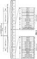
- FIGURE 5 is a block diagram illustrating TDM partitioning in a heterogeneous network according to one aspect of the disclosure.
- a first row of blocks illustrate sub frame assignments for a femto eNodeB
- a second row of blocks illustrate sub frame assignments for a macro eNodeB.
- Each of the eNodeBs has a static protected sub frame during which the other eNodeB has a static prohibited sub frame.
- the femto eNodeB has a protected sub frame (U sub frame) in sub frame 0 corresponding to a prohibited sub frame (N sub frame) in sub frame 0.
- the macro eNodeB has a protected sub frame (U sub frame) in sub frame 7 corresponding to a prohibited sub frame (N sub frame) in sub frame 7.
- Sub frames 1-6 are dynamically assigned as either protected sub frames (AU), prohibited sub frames (AN), and common sub frames (AC).
- the dynamically assigned subframes (AU/AN/AC) are referred to herein collectively as "X" subframes.
- both the femto eNodeB and the macro eNodeB may transmit data.
- Protected sub frames have reduced interference and a high channel quality because aggressor eNodeBs are prohibited from transmitting.
- Prohibited sub frames (such as N/AN sub frames) have no data transmission to allow victim eNodeBs to transmit data with low interference levels.
- Common sub frames (such as C/AC sub frames) have a channel quality dependent on the number of neighbor eNodeBs transmitting data. For example, if neighbor eNodeBs are transmitting data on the common sub frames, the channel quality of the common sub frames may be lower than the protected sub frames. Channel quality on common sub frames may also be lower for extended boundary area (EBA) UEs strongly affected by aggressor eNodeBs.
- EBA extended boundary area
- An EBA UE may belong to a first eNodeB but also be located in the coverage area of a second eNodeB.
- a UE communicating with a macro eNodeB that is near the range limit of a femto eNodeB coverage is an EBA UE.
- Another example interference management scheme that may be employed in LTE/-A is the slowly-adaptive interference management.
- resources are negotiated and allocated over time scales that are much larger than the scheduling intervals.
- the goal of the scheme is to find a combination of transmit powers for all of the transmitting eNodeBs and UEs over all of the time or frequency resources that maximizes the total utility of the network.
- "Utility" may be defined as a function of user data rates, delays of quality of service (QoS) flows, and fairness metrics.
- QoS quality of service
- Such an algorithm can be computed by a central entity that has access to all of the information used for solving the optimization and has control over all of the transmitting entities, such as, for example, the network controller 130 ( FIG. 1 ).
- This central entity may not always be practical or even desirable. Therefore, in alternative aspects a distributed algorithm may be used that makes resource usage decisions based on the channel information from a certain set of nodes.
- the slowly-adaptive interference algorithm may be deployed either using a central entity or by distributing the algorithm over various sets of nodes/entities in the network.
- a UE may operate in a dominant interference scenario in which the UE may observe high interference from one or more interfering eNodeBs.
- a dominant interference scenario may occur due to restricted association.
- the UE 120y may be close to the femto eNodeB 110y and may have high received power for the eNodeB 110y.
- the UE 120y may not be able to access the femto eNodeB 110y due to restricted association and may then connect to the macro eNodeB 110c (as shown in FIG. 1 ) or to the femto eNodeB 110z also with lower received power (not shown in FIG.
- the UE 120y may then observe high interference from the femto eNodeB 110y on the downlink and may also cause high interference to the eNodeB 110y on the uplink.
- the eNodeB 110c and the femto eNodeB 110y may communicate over the backhaul to negotiate resources.
- the femto eNodeB 110y agrees to cease transmission on one of its channel resources, such that the UE 120y will not experience as much interference from the femto eNodeB 110y as it communicates with the eNodeB 110c over that same channel.
- timing delays of downlink signals may also be observed by the UEs, even in synchronous systems, because of the differing distances between the UEs and the multiple eNodeBs.
- the eNodeBs in a synchronous system are presumptively synchronized across the system. However, for example, considering a UE that is a distance of 5 km from the macro eNodeB, the propagation delay of any downlink signals received from that macro eNodeB would be delayed approximately 16.67 ⁇ s (5 km ⁇ 3 x 10⁸, i.e., the speed of light, 'c'). Comparing that downlink signal from the macro eNodeB to the downlink signal from a much closer femto eNodeB, the timing difference could approach the level of a time tracking loop (TTL) error.
- TTL time tracking loop
- Interference cancellation often uses cross correlation properties between a combination of multiple versions of the same signal. By combining multiple copies of the same signal, interference may be more easily identified because, while there will likely be interference on each copy of the signal, it will likely not be in the same location. Using the cross correlation of the combined signals, the actual signal portion may be determined and distinguished from the interference, thus, allowing the interference to be canceled.
- a position location server may rely on a UE to detect a time difference between signals received from various macro base stations. The UE reports the detected time difference back to the position location server. The location server then compiles the received data and through triangulation determines the location of the UE.
- One example system includes one or more remote radio head (RRH), which is similar to a base station of a pico cell, and one or more macro eNodeB (eNodeB), which is a base station of a macro cell.
- RRH remote radio head
- eNodeB macro eNodeB
- the remote radio heads and macro eNodeB have the same physical cell ID (PCI).
- a position reference signal is generated based on or derived from the physical cell ID of the transmitting node (e.g. RRH, pico cell, or macro eNodeB).
- the resulting position reference signals (PRSs) transmitted from the remote radio heads and macro cells is the same, then determining the position location of the UE may be affected. For example, if the UE is far from the eNodeB, but close to the remote radio head, the UE reports back the position reference signal from the eNodeB, which is the same as the position reference signal from the remote radio head. Consequently, the location server will interpret the information incorrectly, as though the UE is near the eNodeB.
- the present disclosure helps prevent different nodes from transmitting the same position reference signal (PRS).
- the position location reference signal (PRS) transmissions from the remote radio head are silenced.
- the remote radio head does not transmit the position reference signal.
- Silencing the position reference signal transmission does not involve any input from the network side.
- Advantages of this solution include easy scaling at the location server and not having to re-plan position reference signal re-use.
- all nodes with the same position reference signal, except the highest power node may be silenced. For example, in aspects where the eNodeB has the highest power, the lower powered remote radio heads are silenced. In some aspects, only nodes considered low power nodes (e.g., RRHs, pico cells and femto cells), with the same position reference signal are silenced.
- a new identification is assigned to each remote radio head.
- a new virtual identification is assigned to each remote radio head and eNodeB.
- the virtual ID not the PCI (physical cell ID)
- PCI physical cell ID
- an identifier such as the cell global identification (CGI) of each remote radio head and eNodeB may be used to generate the position reference signal.
- the cell global identification (CGI) may also be referred to as a global cell identification (GCI).
- GCI global cell identification
- Using the cell global identification (CGI) to generate the position reference signal provides a known location for the remote radio head, which again may increase accuracy for determining position location. Additionally reuse is coordinated and CGIs are provided that do not collide with existing IDs.
- the location server may configure the remote radio heads in different macro cells to avoid CGI collision.
- the UE may be informed of the position reference signal configuration of at least one macro cell and one or more remote radio heads. Thus, the UEs are aware of which cells to measure.
- the UEs that are close to a neighboring macro cell may also be informed of the position reference signal configurations of neighboring macros cells.
- a schedule or pattern is mapped that illustrates when each of the nodes is broadcasting a position reference signal.
- the UE is informed of this mapping function and the position of the UE can then be calculated because the UE knows from which node the position reference signal was transmitted, even though the position reference signal itself may not identify (or explicitly reveal) which node transmitted the signal.
- the UE location can be determined even if the nodes are transmitting the same position reference signal, because not all the nodes are transmitting the position reference signals at the same time.
- uplink transmission are used for location determinations.
- the reference time signal difference may be measured at each node for triangulation based on sounding reference signals (SRSs), physical uplink control channel (PUCCH) transmissions or physical uplink shared channel (PUSCH) transmissions.
- SRSs sounding reference signals
- PUCCH physical uplink control channel
- PUSCH physical uplink shared channel
- the macro cell and associated remote radio head location is known by the location server.
- the position location based on uplink data may be merged with downlink measurements when the remote radio head position reference signal transmissions are silenced or when the position reference signal is derived from a unique virtual ID or the assigned cell global identification (CGI).
- CGI cell global identification
- FIGURES 6A-6C are block diagrams illustrating methods for configuring remote radio heads.
- FIGURE 6A provides a method 601 where multiple remote radio heads (RRHs) are configured.
- the RRHs are configured to prevent position reference signal (PRS) transmissions on the same subframes where a macro eNodeB transmits PRS.
- PRS position reference signal
- the RRHs having the same physical cell ID (PCI) as a macro eNodeB, and a lower power than the macro eNodeB, are configured. Transmissions may be prevented by silencing the PRS transmissions or by configuring the RRHs not to transmit PRS.
- the remote radio heads communicate in accordance with the configuration.
- a method 602 is illustrated.
- the remote radio heads (RRHs) are configured.
- the RRHs receive uplink transmissions from a UE (user equipment).
- the position location of a UE is determined based on received signal time difference (RSTD) measurements of the uplink transmissions at the RRHs and macro eNodeB.
- RSTD received signal time difference
- a method 603 is provided.
- a unique position location reference signal PRS
- RRH remote radio head
- CGIs unique cell global identifications
- FIGURES 7 - 9 are diagrams illustrating an example of a hardware implementation for an apparatus 700, 800, 900 employing a processing system 714, 814, 914.
- the processing system 714, 814, 914 may be implemented with a bus architecture, represented generally by the bus 724, 824, 924.
- the bus 724, 824, 924 may include any number of interconnecting buses and bridges depending on the specific application of the processing system 714, 814, 914 and the overall design constraints.
- the bus 724, 824, 924 links together various circuits including one or more processors and/or hardware modules, represented by the processor 708, 808, 908, the modules 702, 704, 802, 804, 902, 904 and the computer-readable medium 706, 806, 906.
- the bus 724, 824, 924 may also link various other circuits such as timing sources, peripherals, voltage regulators, and power management circuits, which are well known in the art, and therefore, will not be described any further.
- the apparatus includes a processing system 714, 814, 914 coupled to a transceiver 710, 810, 910.
- the transceiver 710, 810, 910 is coupled to one or more antennas 720, 820, 920.
- the transceiver 710, 810, 910 enables communicating with various other apparatus over a transmission medium.
- the processing system 714, 814, 914 includes a processor 708, 808, 908 coupled to a computer-readable medium 706, 806, 906.
- the processor 708, 808, 908 is responsible for general processing, including the execution of software stored on the computer-readable medium 706, 806, 906.
- the software when executed by the processor 708, 808, 908 causes the processing system 714, 814, 914 to perform the various functions described for any particular apparatus.
- the computer-readable medium 706, 806, 906 may also be used for storing data that is manipulated by the processor 708, 808, 908 when executing software.
- the processing system of FIGURE 7 includes a configuring module 702 and a communicating module 704.
- the configuring module can configure remote radio heads (RRHs), each having the same physical cell ID as a macro eNodeB, to prevent position location reference signal (PRS) transmissions on the subframes where a macro eNodeB is transmitting PRS.
- the communicating module can cause the remote radio heads to communicate in accordance with the configuration.
- the modules may be software modules running in the processor 708, resident/stored in the computer readable medium 706, one or more hardware modules coupled to the processor 708, or some combination thereof.
- the processing system 714 may be a component of the eNodeB 110, 110x, 110y, and may include the memory 442, the transmit processor 420, the receive processor 438, the modulators/demodulators 432a-t, the antenna 434a-t, and/or the controller/processor 440.
- the processing system of FIGURE 8 includes a configuring module 802, a receiving module 804 and a determining module 806.
- the configuring module can configure a plurality of remote radio heads (RRHs).
- the receiving module can receive uplink transmissions from a user equipment.
- the determining module can determine a position location of the UE.
- the modules may be software modules running in the processor 808, resident/stored in the computer readable medium 806, one or more hardware modules coupled to the processor 808, or some combination thereof.
- the processing system 814 may be a component of the eNodeB 110, 1 10x, 110y, and may include the memory 442, the transmit processor 420, the receive processor 438, the modulators/demodulators 432a-t, the antenna 434a-t, and/or the controller/processor 440.
- the processing system of FIGURE 9 includes a generating module 902 and a transmitting module 904.
- the generating module can generate a unique position location reference signal (PRS) for a remote radio head (RRH) based on a virtual cell ID or unique cell global identifications (CGIs) of the remote radio head.
- the transmitting module can cause the remote radio head to transmit the unique position location signal.
- the modules may be software modules running in the processor 908, resident/stored in the computer readable medium 906, one or more hardware modules coupled to the processor 908, or some combination thereof.
- the processing system 914 may be a component of the eNodeB 110, 110x, 110y, and may include the memory 442, the transmit processor 420, the receive processor 438, the modulators/demodulators 432a-t, the antenna 434a-t, and/or the controller/processor 440.
- an eNodeB 110 configures a remote radio head for wireless communication and includes a means for configuring.
- the configuring means may be the transmit processor 420, the modulators 432a-t, the antenna 434a-t, the controller/processor 440, and/or the memory 442 configured to perform the functions recited by the configuring means.
- the eNodeB 110 is also configured to include a means for communicating.
- the communicating means may be the transmit processor 420, the modulators 432a-t, the antenna 434a-t, the controller/processor 440, the memory 442 and/or the receive processor 438 configured to perform the functions recited by the communicating means.
- the aforementioned means may be any module or any apparatus configured to perform the functions recited by the aforementioned means.
- a base station 110 (e.g., a remote radio head) includes a means for configuring.
- the configuring means may be the transmit processor 420, the modulators 432a-t, the antenna 434a-t, the controller/processor 440, and/or the memory 442 configured to perform the functions recited by the configuring means.
- the eNodeB 110 is also configured to include a means for receiving.
- the receiving means may be the antenna 434a-t, the demodulators 432a-t, the MIMO detector 436, the receive processor 438, the controller/processor 440 and/or the memory 442 configured to perform the functions recited by the receiving means.
- the aforementioned means may be any module or any apparatus configured to perform the functions recited by the aforementioned means.
- a base station 110 (e.g., a remote radio head) includes a means for generating.
- the generating means may be the controller/processor 440, and/or the memory 442 configured to perform the functions recited by the configuring means.
- the base station 110 is also configured to include a means for transmitting.
- the transmitting means may be the transmit processor 420, the modulators 432a-t, the antenna 434a-t, the controller/processor 440, and/or the memory 442 configured to perform the functions recited by the communicating means.
- the aforementioned means may be any module or any apparatus configured to perform the functions recited by the aforementioned means.
- DSP digital signal processor
- ASIC application specific integrated circuit
- FPGA field programmable gate array
- a general-purpose processor may be a microprocessor, but in the alternative, the processor may be any conventional processor, controller, microcontroller, or state machine.
- a processor may also be implemented as a combination of computing devices, e.g., a combination of a DSP and a microprocessor, a plurality of microprocessors, one or more microprocessors in conjunction with a DSP core, or any other such configuration.
- a software module may reside in RAM memory, flash memory, ROM memory, EPROM memory, EEPROM memory, registers, hard disk, a removable disk, a CD-ROM, or any other form of storage medium known in the art.
- An exemplary storage medium is coupled to the processor such that the processor can read information from, and write information to, the storage medium.
- the storage medium may be integral to the processor.
- the processor and the storage medium may reside in an ASIC.
- the ASIC may reside in a user terminal.
- the processor and the storage medium may reside as discrete components in a user terminal.
- the functions described may be implemented in hardware, software, firmware, or any combination thereof. If implemented in software, the functions may be stored on or transmitted over as one or more instructions or code on a computer-readable medium.
- Computer-readable media includes both computer storage media and communication media including any medium that facilitates transfer of a computer program from one place to another.
- a storage media may be any available media that can be accessed by a general purpose or special purpose computer.
- such computer-readable media can comprise RAM, ROM, EEPROM, CD-ROM or other optical disk storage, magnetic disk storage or other magnetic storage devices, or any other medium that can be used to carry or store desired program code means in the form of instructions or data structures and that can be accessed by a general-purpose or special-purpose computer, or a general-purpose or special-purpose processor. Also, any connection is properly termed a computer-readable medium.
- Disk and disc includes compact disc (CD), laser disc, optical disc, digital versatile disc (DVD), floppy disk and blu-ray disc where disks usually reproduce data magnetically, while discs reproduce data optically with lasers. Combinations of the above should also be included within the scope of computer-readable media.
- a method of wireless communication comprising configuring a plurality of remote radio heads (RRHs), each having a same physical cell identity (PCI) as a macro eNodeB, to prevent position location reference signal (PRS) transmissions on subframes where the macro eNodeB transmits PRS and communicating in accordance with the configuration.
- configuring a plurality of remote radio heads may comprise configuring no PRS transmissions at the remote radio heads.
- configuring a plurality of remote heads may comprise silencing PRS transmissions at the remote radio heads.
- the method may also comprise configuring a PRS (position reference signal) transmission pattern at the remote radio heads different from a macro eNodeB PRS transmission pattern.
- a method of wireless communication comprising configuring a plurality of remote radio heads (RRHs), receiving uplink transmissions from a user equipment (UE) and determining a position location of the UE based on received signal time difference (RSTD) measurements of the received uplink transmissions at the RRHs and macro eNodeB.
- the method may further comprise combining the RSTD measurements of the received uplink transmissions at the RRHs and macro eNodeB with measurements from the UE, in which the UE measurements are based on RSTD of position location reference signal (PRS) transmissions.
- PRS position location reference signal
- the measurements from the UE may be based on RRHs that have been configured to silence PRS transmissions on subframes where a macro eNodeB transmits PRS.
- a method of wireless communication comprising generating a unique position location reference signal (PRS) for a remote radio head based on at least one of a virtual cell ID or unique cell global identification (CGI) of the remote radio head and transmitting the unique position location reference signal.
- the method may comprise signaling to a user equipment (UE) that the position location reference signal is based on at least one of the cell global identification or the virtual cell ID.
- the method may comprise signaling to a user equipment (UE), a position reference signal configuration of a plurality of remote radio heads in neighboring cells when the UE is near a serving cell boundary.
- the method may also comprise receiving uplink transmissions from a user equipment (UE) and determining a position location of the UE based on the received uplink transmissions.
- an apparatus for wireless communication comprising a memory and at least one processor coupled to the memory, the at least one processor being configured to configure a plurality of remote radio heads (RRHs), each having a same physical cell identity (PCI) as a macro eNodeB, to prevent position location reference signal (PRS) transmissions on subframes where the macro eNodeB transmits PRS and to communicate in accordance with the configuration.
- the processor may configure the plurality of remote radio heads by configuring no PRS transmissions at the remote radio heads.
- the processor may configure the plurality of remote heads by silencing PRS transmissions at the remote radio heads.
- the processor may configure a PRS (position reference signal) transmission pattern at the remote radio heads different from a macro eNodeB PRS transmission pattern.
- an apparatus for wireless communication comprising a memory and at least one processor coupled to the memory, the at least one processor being configured to configure a plurality of remote radio heads (RRHs), to receive uplink transmissions from a user equipment (UE) and to determine a position location of the UE based on received signal time difference (RSTD) measurements of the received uplink transmissions at the RRHs and macro eNodeB.
- the processor may further be configured to combine the RSTD measurements of the received uplink transmissions at the RRHs and macro eNodeB with measurements from the UE, in which the UE measurements are based on RSTD of position location reference signal (PRS) transmissions.
- PRS position location reference signal
- the measurements from the UE may be based on RRHs that have been configured to silence PRS transmissions on sub frames where a macro eNodeB transmits PRS.
- an apparatus for wireless communication comprising a memory and at least one processor coupled to the memory, the at least one processor being configured to generate a unique position location reference signal (PRS) for a remote radio head based on at least one of a virtual cell ID or unique cell global identification (CGI) of the remote radio head and to transmit the unique position location reference signal.
- the processor may be configured to signal to a user equipment (UE) that the position location reference signal is based on at least one of the cell global identification or the virtual cell ID.
- the processor may be configured to signal to a user equipment (UE), a position reference signal configuration of a plurality of remote radio heads in neighboring cells when the UE is near a serving cell boundary.
- the processor may be configured to receive uplink transmissions from a user equipment (UE) and to determine a position location of the UE based on the received uplink transmissions.
- a computer program product for wireless communication in a wireless network comprising a non-transitory computer-readable medium having non-transitory program code recorded thereon, the program code comprising program code to configure a plurality of remote radio heads (RRHs), each having a same physical cell identity (PCI) as a macro eNodeB, to prevent position location reference signal (PRS) transmissions on subframes where the macro eNodeB transmits PRS and program code to communicate in accordance with the configuration.
- RRHs remote radio heads
- PCI physical cell identity
- PRS position location reference signal
- a computer program product for wireless communication in a wireless network comprising a non-transitory computer-readable medium having non-transitory program code recorded thereon, the program code comprising program code to configure a plurality of remote radio heads (RRHs), program code to receive uplink transmissions from a user equipment (UE) and program code to determine a position location of the UE based on received signal time difference (RSTD) measurements of the received uplink transmissions at the RRHs and macro eNodeB.
- RRHs remote radio heads
- UE user equipment
- RSTD received signal time difference
- a computer program product for wireless communication in a wireless network comprising a non-transitory computer-readable medium having non-transitory program code recorded thereon, the program code comprising program code to generate a unique position location reference signal (PRS) for a remote radio head based on at least one of a virtual cell ID or unique cell global identification (CGI) of the remote radio head and program code to transmit the unique position location reference signal.
- PRS unique position location reference signal
- CGI unique cell global identification
- an apparatus for wireless communication comprising means for configuring a plurality of remote radio heads (RRHs), each having a same physical cell identity (PCI) as a macro eNodeB, to prevent position location reference signal (PRS) transmissions on subframes where the macro eNodeB transmits PRS and means for communicating in accordance with the configuration.
- RRHs remote radio heads
- PCI physical cell identity
- PRS position location reference signal
- an apparatus for wireless communication comprising means for configuring a plurality of remote radio heads (RRHs), means for receiving uplink transmissions from a user equipment (UE) and means for determining a position location of the UE based on received signal time difference (RSTD) measurements of the received uplink transmissions at the RRHs and macro eNodeB.
- RRHs remote radio heads
- UE user equipment
- RSTD received signal time difference
- an apparatus for wireless communication comprising means for generating a unique position location reference signal (PRS) for a remote radio head based on at least one of a virtual cell ID or unique cell global identification (CGI) of the remote radio head and means for transmitting the unique position location reference signal.
- PRS unique position location reference signal
- CGI unique cell global identification
Landscapes
- Engineering & Computer Science (AREA)
- Signal Processing (AREA)
- Computer Networks & Wireless Communication (AREA)
- Mobile Radio Communication Systems (AREA)
- Physics & Mathematics (AREA)
- General Physics & Mathematics (AREA)
- Radar, Positioning & Navigation (AREA)
- Remote Sensing (AREA)
Claims (7)
- Procédé de communication sans fil, le procédé étant effectué par un macro eNodeB (110a, 110b, 110C) et comprenant :la génération (630) d'un signal de référence de localisation de position, PRS, unique pour une tête radio distante, RRH, ayant une même identité de cellule physique, PCI, que le macro eNodeB (110a, 110b, 110c), le PRS unique étant basé sur un ID de cellule virtuelle de la tête radio distante ;la configuration de la RRH pour transmettre (632) le PRS unique à un équipement utilisateur, UE, (120) ; etle fait de signaler à l'UE (120) que le signal de référence de localisation de position est basé sur l'ID de cellule virtuelle.
- Procédé selon la revendication 1, comprenant en outre :
le fait de signaler à l'UE (120), une configuration de signal de référence de position d'une pluralité de têtes radio distantes dans des cellules voisines lorsque l'UE (120) est près d'une frontière de cellule de desserte. - Procédé selon la revendication 1, comprenant en outre :la réception de transmissions de liaison montante de l'UE (120) ; etla détermination d'une localisation de position de l'UE (120) sur la base des transmissions de liaison montante reçues.
- Appareil pour une communication sans fil, dans lequel l'appareil est un macro eNodeB (110a, 110b, 110c), l'appareil comprenant :des moyens pour générer un signal de référence de localisation de position, PRS, unique pour une tête radio distante, RRH, ayant une même identité de cellule physique, PCI, que le macro eNodeB (110a, 110b, 110c), le PRS unique basé sur un ID de cellule virtuelle de la tête radio distante ; des moyens pour configurer la RRH pour transmettre le PRS unique à un équipement utilisateur, UE (120) ; etdes moyens pour signaler à l'UE (120) que le signal de référence de localisation de position est basé sur l'ID de cellule virtuelle.
- Appareil selon la revendication 4, comprenant en outre :
des moyens pour signaler à l'UE (120), une configuration de signal de référence de position d'une pluralité de têtes radio distantes dans des cellules voisines lorsque l'UE (120) est près d'une frontière de cellule de desserte. - Appareil selon la revendication 4, comprenant en outre :des moyens pour recevoir une transmission de liaison montante de l'UE (120) ; etdes moyens pour déterminer une localisation de position de l'UE (120) sur la base des transmissions de liaison montante reçues.
- Produit de programme informatique, comprenant :
un support lisible par ordinateur sur lequel est enregistré un code de programme, le code de programme amenant un ordinateur à effectuer un procédé selon l'une quelconque des revendications 1 à 3 lorsqu'il est exécuté.
Applications Claiming Priority (4)
| Application Number | Priority Date | Filing Date | Title |
|---|---|---|---|
| US201161445489P | 2011-02-22 | 2011-02-22 | |
| US13/401,696 US9258718B2 (en) | 2011-02-22 | 2012-02-21 | Positioning location for remote radio heads (RRH) with same physical cell identity (PCI) |
| PCT/US2012/026023 WO2012116007A1 (fr) | 2011-02-22 | 2012-02-22 | Localisation de position pour des architectures remote radio head (rrh) avec le même identifiant de cellule physique (pci) |
| EP12706417.8A EP2679062A1 (fr) | 2011-02-22 | 2012-02-22 | Localisation de position pour des architectures remote radio head (rrh) avec le même identifiant de cellule physique (pci) |
Related Parent Applications (1)
| Application Number | Title | Priority Date | Filing Date |
|---|---|---|---|
| EP12706417.8A Division EP2679062A1 (fr) | 2011-02-22 | 2012-02-22 | Localisation de position pour des architectures remote radio head (rrh) avec le même identifiant de cellule physique (pci) |
Publications (2)
| Publication Number | Publication Date |
|---|---|
| EP3151606A1 EP3151606A1 (fr) | 2017-04-05 |
| EP3151606B1 true EP3151606B1 (fr) | 2019-08-07 |
Family
ID=45771951
Family Applications (2)
| Application Number | Title | Priority Date | Filing Date |
|---|---|---|---|
| EP12706417.8A Withdrawn EP2679062A1 (fr) | 2011-02-22 | 2012-02-22 | Localisation de position pour des architectures remote radio head (rrh) avec le même identifiant de cellule physique (pci) |
| EP16199799.4A Active EP3151606B1 (fr) | 2011-02-22 | 2012-02-22 | Positionnement d'emplacement pour têtes radio distantes (trd) ayant la même identité de cellule physique (pci) |
Family Applications Before (1)
| Application Number | Title | Priority Date | Filing Date |
|---|---|---|---|
| EP12706417.8A Withdrawn EP2679062A1 (fr) | 2011-02-22 | 2012-02-22 | Localisation de position pour des architectures remote radio head (rrh) avec le même identifiant de cellule physique (pci) |
Country Status (6)
| Country | Link |
|---|---|
| US (4) | US9258718B2 (fr) |
| EP (2) | EP2679062A1 (fr) |
| JP (4) | JP2014509147A (fr) |
| KR (1) | KR101601855B1 (fr) |
| CN (3) | CN105979536B (fr) |
| WO (1) | WO2012116007A1 (fr) |
Families Citing this family (54)
| Publication number | Priority date | Publication date | Assignee | Title |
|---|---|---|---|---|
| CN103563270A (zh) * | 2011-02-11 | 2014-02-05 | 韩国电子通信研究院 | 使用多传送和接收点的无线通信系统 |
| US9258718B2 (en) | 2011-02-22 | 2016-02-09 | Qualcomm Incorporated | Positioning location for remote radio heads (RRH) with same physical cell identity (PCI) |
| WO2013036060A1 (fr) * | 2011-09-09 | 2013-03-14 | 엘지전자 주식회사 | Procédé et appareil pour détecter les positions de terminaux dans un système à nœuds multiples |
| US9294875B2 (en) * | 2011-09-30 | 2016-03-22 | Electronics And Telecommunications Research Institute | Method for determining position of terminal in cellular mobile communication system |
| WO2013172588A1 (fr) * | 2012-05-14 | 2013-11-21 | 엘지전자 주식회사 | Procédé de mesure de position dans un système de communication sans fil |
| US8838119B2 (en) | 2012-06-26 | 2014-09-16 | Futurewei Technologies, Inc. | Method and system for dynamic cell configuration |
| KR101235204B1 (ko) | 2012-09-28 | 2013-02-20 | 주식회사 엘지유플러스 | 무선 통신 시스템에서 원격 무선 헤드 식별자를 이용한 위치측정 방법 및 이를 위한 시스템 |
| KR101222617B1 (ko) | 2012-09-28 | 2013-01-16 | 주식회사 엘지유플러스 | 무선 통신 시스템에서 벤더 식별자를 이용한 적응적 위치측정 방법 및 이를 위한 시스템 |
| EP2907351A4 (fr) * | 2012-10-10 | 2016-06-15 | Ericsson Telefon Ab L M | Méthode et noeud pour le positionnement dans une cellule combinée |
| US9651653B2 (en) * | 2012-12-24 | 2017-05-16 | Qualcomm Incorporated | Positioning reference signal (PRS) generation for multiple transmit antenna systems |
| WO2014109782A1 (fr) | 2013-01-14 | 2014-07-17 | Andrew Llc | Système intercepteur pour caractériser des données numériques dans un système de télécommunication |
| US20150180627A1 (en) * | 2013-01-17 | 2015-06-25 | Telefonaktiebolaget L M Ericsson (Publ) | Resource scheduling for downlink transmissions |
| US9319916B2 (en) | 2013-03-15 | 2016-04-19 | Isco International, Llc | Method and appartus for signal interference processing |
| WO2015099582A1 (fr) * | 2013-12-23 | 2015-07-02 | Telefonaktiebolaget L M Ericsson (Publ) | Déterminer une position d'un dispositif sans fil à l'aide de dispositifs radio de tête distants ayant plusieurs dispositifs d'antennes |
| US9774429B2 (en) | 2014-03-12 | 2017-09-26 | Qualcomm Incorporated | Techniques for transmitting positioning reference signals in an unlicensed radio frequency spectrum band |
| EP3113555B1 (fr) | 2014-03-17 | 2019-05-08 | Huawei Technologies Co., Ltd. | Procédé et dispositif de localisation |
| CN109946647B (zh) * | 2014-03-19 | 2020-07-07 | 华为技术有限公司 | 一种定位装置及方法 |
| US10135586B2 (en) | 2014-03-20 | 2018-11-20 | Intel IP Corporation | Reference signal enhancement for shared cell |
| WO2015156714A1 (fr) * | 2014-04-09 | 2015-10-15 | Telefonaktiebolaget L M Ericsson (Publ) | Détermination de la position d'un dispositif sans fil à l'aide de dispositifs têtes radio distantes |
| WO2015178830A1 (fr) * | 2014-05-20 | 2015-11-26 | Telefonaktiebolaget L M Ericsson (Publ) | Procédés et appareils de positionnement dans des cellules réseau ayant une pluralité de points de transmission |
| JP6368161B2 (ja) * | 2014-06-18 | 2018-08-01 | 株式会社Nttドコモ | 情報処理システム及び情報処理方法 |
| CN106461748A (zh) | 2014-06-25 | 2017-02-22 | 英特尔公司 | 长期演进协作多点通信系统中的用户设备定位 |
| WO2016032200A2 (fr) * | 2014-08-28 | 2016-03-03 | 엘지전자(주) | Procédé permettant d'effectuer un positionnement dans un système de communication sans fil, et dispositif associé |
| US10341980B2 (en) * | 2014-08-28 | 2019-07-02 | Lg Electronics Inc. | Method for receiving reference signal in wireless communication system and device for same |
| EP3192315B1 (fr) * | 2014-09-10 | 2023-06-14 | Telefonaktiebolaget LM Ericsson (publ) | Détermination de la position d'un dispositif sans fil |
| CN105830509B (zh) * | 2014-09-16 | 2019-10-18 | 华为技术有限公司 | 移动终端定位方法、基站以及节点 |
| CN105992339B (zh) * | 2015-03-06 | 2019-10-11 | 上海诺基亚贝尔股份有限公司 | 一种在室内通信系统中用于实施otdoa的方法及装置 |
| US9641984B2 (en) * | 2015-06-05 | 2017-05-02 | Qualcomm Incorporated | Support of OTDOA positioning using ambiguous cells |
| CA2995679A1 (fr) | 2015-08-14 | 2017-02-23 | Telefonaktiebolaget Lm Ericsson (Publ) | Procedes et appareils de positionnement sur la base d'une retroaction de caracteristique de fonction de correlation de signal |
| US9906911B2 (en) | 2015-09-04 | 2018-02-27 | Telefonaktiebolaget L M Ericsson (Publ) | Systems and methods for UE positioning in a distributed antenna wireless system |
| WO2017037518A1 (fr) * | 2015-09-04 | 2017-03-09 | Telefonaktiebolaget Lm Ericsson (Publ) | Positionnement d'ue basé sur la synchronisation dans un environnement de cellule partagée |
| CN106507471A (zh) * | 2015-09-07 | 2017-03-15 | 北京信威通信技术股份有限公司 | 无线通信系统中的定位增强方法、装置及系统 |
| CN106507472A (zh) * | 2015-09-07 | 2017-03-15 | 北京信威通信技术股份有限公司 | 一种无线通信系统中的定位方法 |
| WO2017061915A1 (fr) * | 2015-10-08 | 2017-04-13 | Telefonaktiebolaget Lm Ericsson (Publ) | Combinaison de signaux radio de liaison montante |
| US9706391B2 (en) | 2015-10-08 | 2017-07-11 | At&T Intellectual Property I, L.P. | Initiating signaling in mobile management entity pools using workflows |
| CN106851550B (zh) | 2015-12-04 | 2020-02-14 | 华为技术有限公司 | 一种定位终端的方法以及基带单元 |
| US10608919B2 (en) | 2016-02-19 | 2020-03-31 | Commscope Technologies Llc | Passive intermodulation (PIM) testing in distributed base transceiver station architecture |
| WO2017194675A1 (fr) * | 2016-05-13 | 2017-11-16 | Telefonaktiebolaget Lm Ericsson (Publ) | Procédés, équipement d'utilisateur, émetteur radio et nœud de réseau pour gérer des signaux de référence de positionnement |
| CA3024175A1 (fr) | 2016-06-01 | 2017-12-07 | Isco International, Llc | Procede et appareil aptes a executer un conditionnement de signal afin d'attenuer une interference detectee dans un systeme de communication |
| US11122535B2 (en) * | 2016-07-15 | 2021-09-14 | Qualcomm Incorporated | Techniques for locating devices using narrowband positioning reference signals |
| US10609582B2 (en) | 2016-09-08 | 2020-03-31 | Commscope Technologies Llc | Interference detection and identification in wireless network from RF or digitized signal |
| US11234206B2 (en) | 2016-09-30 | 2022-01-25 | Telefonaktiebolaget Lm Ericsson (Publ) | Wireless device, a core network node and methods therein |
| US10298279B2 (en) | 2017-04-05 | 2019-05-21 | Isco International, Llc | Method and apparatus for increasing performance of communication paths for communication nodes |
| US10631367B2 (en) | 2017-04-14 | 2020-04-21 | Verizon Patent And Licensing Inc. | Virtualized equipment for multi-network and cross cell utilization |
| US10470079B2 (en) * | 2017-04-14 | 2019-11-05 | Verizon Patent And Licensing Inc. | Systems and method for cross cell aggregation using virtualized equipment |
| US10812121B2 (en) | 2017-08-09 | 2020-10-20 | Isco International, Llc | Method and apparatus for detecting and analyzing passive intermodulation interference in a communication system |
| US10284313B2 (en) | 2017-08-09 | 2019-05-07 | Isco International, Llc | Method and apparatus for monitoring, detecting, testing, diagnosing and/or mitigating interference in a communication system |
| CN109640336B (zh) * | 2017-09-30 | 2020-09-11 | 上海华为技术有限公司 | 一种射频头端定位方法及射频头端定位系统和计算机介质 |
| WO2020060119A1 (fr) * | 2018-09-21 | 2020-03-26 | 엘지전자 주식회사 | Procédé de localisation d'un terminal dans un système de communication sans fil et dispositif afférent |
| US11412392B2 (en) | 2019-05-29 | 2022-08-09 | Commscope Technologies Llc | Distributed relay node |
| US20210344469A1 (en) * | 2020-05-04 | 2021-11-04 | Qualcomm Incorporated | Estimating features of a radio frequency band based on an inter-band reference signal |
| US11382027B2 (en) * | 2020-08-17 | 2022-07-05 | Qualcomm Incorporated | Layer 2 remote radio head configuration |
| US11445470B2 (en) * | 2021-02-02 | 2022-09-13 | Qualcomm Incorporated | Position measurement in presence of MBSFN signals |
| US11317370B1 (en) * | 2021-02-26 | 2022-04-26 | Qualcomm Incorporated | Interference avoidance for ranging and positioning of distributed devices |
Family Cites Families (33)
| Publication number | Priority date | Publication date | Assignee | Title |
|---|---|---|---|---|
| US6289280B1 (en) | 1999-12-10 | 2001-09-11 | Qualcomm Incorporated | Method and apparatus for determining an algebraic solution to GPS terrestrial hybrid location system equations |
| US7130642B2 (en) | 2003-03-03 | 2006-10-31 | Qualcomm Incorporated | Method and apparatus for performing position determination in a wireless communication network with repeaters |
| US8437288B2 (en) | 2006-03-07 | 2013-05-07 | Qualcomm Incorporated | Network selection by wireless terminals |
| US8666428B2 (en) * | 2008-01-29 | 2014-03-04 | Alcatel Lucent | Method to support user location in in-structure coverage systems |
| JP2009246733A (ja) | 2008-03-31 | 2009-10-22 | Brother Ind Ltd | 基地局及び測位システム |
| US8442069B2 (en) | 2008-04-14 | 2013-05-14 | Qualcomm Incorporated | System and method to enable uplink control for restricted association networks |
| CN102057294B (zh) * | 2008-06-06 | 2014-03-26 | 上海贝尔股份有限公司 | 用于分布式天线系统中室内无线定位的设备和方法 |
| CN101621844A (zh) * | 2008-06-30 | 2010-01-06 | 华为技术有限公司 | 定位方法、装置和系统 |
| US8982851B2 (en) * | 2009-01-06 | 2015-03-17 | Qualcomm Incorporated | Hearability improvements for reference signals |
| US7940740B2 (en) * | 2009-02-03 | 2011-05-10 | Motorola Mobility, Inc. | Apparatus and method for communicating and processing a positioning reference signal based on identifier associated with a base station |
| KR101476205B1 (ko) | 2009-03-17 | 2014-12-24 | 엘지전자 주식회사 | 무선 통신 시스템에서 위치 기반 서비스를 위한 참조 신호 송신 방법 및 이를 위한 장치 |
| US8730925B2 (en) * | 2009-04-09 | 2014-05-20 | Motorola Mobility Llc | Method and apparatus for generating reference signals for accurate time-difference of arrival estimation |
| US9002354B2 (en) | 2009-06-12 | 2015-04-07 | Google Technology Holdings, LLC | Interference control, SINR optimization and signaling enhancements to improve the performance of OTDOA measurements |
| EP3206447A1 (fr) | 2009-06-24 | 2017-08-16 | IDTP Holdings, Inc. | Procédés et agencements dans un système de télécommunications pour assister la localisation |
| CN101616360B (zh) * | 2009-07-24 | 2012-05-09 | 中兴通讯股份有限公司 | 一种定位参考信号的发送方法及系统 |
| WO2011020008A2 (fr) * | 2009-08-13 | 2011-02-17 | Interdigital Patent Holdings, Inc. | Procédé et appareil pour la prise en charge de mesures de positionnement |
| JP5055329B2 (ja) * | 2009-08-17 | 2012-10-24 | 株式会社エヌ・ティ・ティ・ドコモ | 無線基地局及び移動局 |
| US8248997B2 (en) * | 2009-08-17 | 2012-08-21 | Nokia Corporation | Apparatus and method for positioning a wireless user equipment |
| US20110124347A1 (en) | 2009-09-15 | 2011-05-26 | Byron Hua Chen | Method And Apparatus for UE Positioning in LTE Networks |
| KR20110037430A (ko) * | 2009-10-06 | 2011-04-13 | 주식회사 팬택 | 무선통신 시스템에서 신호 전송방법 및 그 송신장치, 이에 대응하는 수신장치 |
| US8600398B2 (en) * | 2009-11-03 | 2013-12-03 | Telefonaktiebolaget Lm Ericsson (Publ) | Method, apparatus and system for defining positioning configuration in a wireless network |
| US20110176440A1 (en) | 2010-01-15 | 2011-07-21 | Motorola-Mobility, Inc. | Restrictions on autonomous muting to enable time difference of arrival measurements |
| KR101700956B1 (ko) | 2010-01-29 | 2017-01-31 | 삼성전자주식회사 | 통신 시스템에서 단말의 위치를 식별하는 방법 및 장치 |
| CN101820580A (zh) * | 2010-02-08 | 2010-09-01 | 刘涛 | 一种特殊位置区域未知移动台的识别和定位方法 |
| US20110230144A1 (en) * | 2010-03-17 | 2011-09-22 | Iana Siomina | Method and Apparatus for Muting Signaling in a Wireless Communication Network |
| RU2556241C2 (ru) * | 2010-05-03 | 2015-07-10 | Телефонактиеболагет Л М Эрикссон (Пабл) | Способ и устройство для измерений позиционирования в системах передачи с множественными антеннами |
| EP2604079A2 (fr) * | 2010-08-11 | 2013-06-19 | Telefonaktiebolaget LM Ericsson (publ) | Procédés pour fournir un groupage cellulaire de positionnement, et réseaux et dispositifs connexes |
| US9344248B2 (en) * | 2010-11-12 | 2016-05-17 | Google Technology Holdings LLC | Positioning reference signal assistance data signaling for enhanced interference coordination in a wireless communication network |
| CN103563270A (zh) | 2011-02-11 | 2014-02-05 | 韩国电子通信研究院 | 使用多传送和接收点的无线通信系统 |
| US9258718B2 (en) | 2011-02-22 | 2016-02-09 | Qualcomm Incorporated | Positioning location for remote radio heads (RRH) with same physical cell identity (PCI) |
| WO2012142436A1 (fr) * | 2011-04-13 | 2012-10-18 | Interdigital Patent Holdings, Inc. | Procédé et appareil pour la découverte de petites cellules dans les réseaux hétérogènes |
| EP3091367B1 (fr) * | 2011-08-03 | 2019-10-09 | PoLTE Corporation | Atténuation multivoies dans la télémétrie et suivi d'objets utilisant une technologie rf d'atténuation réduite |
| US9237417B2 (en) | 2013-02-07 | 2016-01-12 | Qualcomm Incorporated | Terrestrial positioning system calibration |
-
2012
- 2012-02-21 US US13/401,696 patent/US9258718B2/en active Active
- 2012-02-22 EP EP12706417.8A patent/EP2679062A1/fr not_active Withdrawn
- 2012-02-22 CN CN201610262140.5A patent/CN105979536B/zh active Active
- 2012-02-22 JP JP2013554683A patent/JP2014509147A/ja not_active Withdrawn
- 2012-02-22 KR KR1020137024659A patent/KR101601855B1/ko active IP Right Grant
- 2012-02-22 CN CN201610262315.2A patent/CN105848184B/zh active Active
- 2012-02-22 WO PCT/US2012/026023 patent/WO2012116007A1/fr active Application Filing
- 2012-02-22 EP EP16199799.4A patent/EP3151606B1/fr active Active
- 2012-02-22 CN CN201280010037.1A patent/CN103404213B/zh active Active
-
2015
- 2015-07-09 JP JP2015137605A patent/JP5992579B2/ja active Active
- 2015-11-12 US US14/940,086 patent/US9521646B2/en active Active
- 2015-12-29 US US14/983,152 patent/US9615348B2/en not_active Expired - Fee Related
-
2016
- 2016-11-01 JP JP2016214180A patent/JP6328727B2/ja active Active
- 2016-11-01 JP JP2016214181A patent/JP6333919B2/ja active Active
- 2016-11-04 US US15/344,354 patent/US9844020B2/en active Active
Non-Patent Citations (1)
| Title |
|---|
| None * |
Also Published As
| Publication number | Publication date |
|---|---|
| US9615348B2 (en) | 2017-04-04 |
| WO2012116007A1 (fr) | 2012-08-30 |
| EP2679062A1 (fr) | 2014-01-01 |
| JP2017050881A (ja) | 2017-03-09 |
| JP2014509147A (ja) | 2014-04-10 |
| KR20130135922A (ko) | 2013-12-11 |
| EP3151606A1 (fr) | 2017-04-05 |
| US20170079003A1 (en) | 2017-03-16 |
| CN105979536A (zh) | 2016-09-28 |
| US9844020B2 (en) | 2017-12-12 |
| JP2017050880A (ja) | 2017-03-09 |
| CN105848184A (zh) | 2016-08-10 |
| KR101601855B1 (ko) | 2016-03-09 |
| US20160072616A1 (en) | 2016-03-10 |
| US9521646B2 (en) | 2016-12-13 |
| CN105848184B (zh) | 2020-05-05 |
| JP5992579B2 (ja) | 2016-09-14 |
| CN103404213A (zh) | 2013-11-20 |
| US9258718B2 (en) | 2016-02-09 |
| CN105979536B (zh) | 2021-02-26 |
| CN103404213B (zh) | 2017-04-26 |
| JP2016001879A (ja) | 2016-01-07 |
| JP6333919B2 (ja) | 2018-05-30 |
| US20160112983A1 (en) | 2016-04-21 |
| US20130051317A1 (en) | 2013-02-28 |
| JP6328727B2 (ja) | 2018-05-23 |
Similar Documents
| Publication | Publication Date | Title |
|---|---|---|
| US9844020B2 (en) | Positioning location for transmitters with same physical cell identity (PCI) | |
| EP2599249B1 (fr) | Signalisation de couche physique d'un enodeb pour un équipement utilisateur dans un système de communications sans fil | |
| EP2559282B1 (fr) | Détermination d'une défaillance de liaison radio avec une meilleure coordination et une meilleure suppression des interférences | |
| EP2559180B1 (fr) | Période silencieuse coordonnée avec configuration de signal de référence de sondage | |
| EP2856826B1 (fr) | Atténuation d'interférences lors d'un déploiement lte asymétrique | |
| EP2777188B1 (fr) | Capacité incrémentale de suppression d'interférences et signalisation | |
| EP2586256B1 (fr) | Mesures d'utilisation des ressources pour réseaux hétérogènes | |
| EP2764743B1 (fr) | Gestion de ressource de liaison montante de pucch en transmission multipoint coordonnée (comp) | |
| EP3130093B1 (fr) | Annulation d'interférences | |
| US9628214B2 (en) | Handling mismatch of control spans between serving cell and interfering cells for control and data channel interference cancellation | |
| WO2013120265A1 (fr) | Régulation de puissance srs pour la planification coordonnée dans des réseaux hétérogènes tdd |
Legal Events
| Date | Code | Title | Description |
|---|---|---|---|
| PUAI | Public reference made under article 153(3) epc to a published international application that has entered the european phase |
Free format text: ORIGINAL CODE: 0009012 |
|
| STAA | Information on the status of an ep patent application or granted ep patent |
Free format text: STATUS: REQUEST FOR EXAMINATION WAS MADE |
|
| 17P | Request for examination filed |
Effective date: 20161121 |
|
| AC | Divisional application: reference to earlier application |
Ref document number: 2679062 Country of ref document: EP Kind code of ref document: P |
|
| AK | Designated contracting states |
Kind code of ref document: A1 Designated state(s): AL AT BE BG CH CY CZ DE DK EE ES FI FR GB GR HR HU IE IS IT LI LT LU LV MC MK MT NL NO PL PT RO RS SE SI SK SM TR |
|
| STAA | Information on the status of an ep patent application or granted ep patent |
Free format text: STATUS: EXAMINATION IS IN PROGRESS |
|
| 17Q | First examination report despatched |
Effective date: 20180404 |
|
| REG | Reference to a national code |
Ref country code: DE Ref legal event code: R079 Ref document number: 602012062862 Country of ref document: DE Free format text: PREVIOUS MAIN CLASS: H04W0024020000 Ipc: H04W0064000000 |
|
| GRAP | Despatch of communication of intention to grant a patent |
Free format text: ORIGINAL CODE: EPIDOSNIGR1 |
|
| STAA | Information on the status of an ep patent application or granted ep patent |
Free format text: STATUS: GRANT OF PATENT IS INTENDED |
|
| RIC1 | Information provided on ipc code assigned before grant |
Ipc: H04W 64/00 20090101AFI20190227BHEP Ipc: G01S 1/20 20060101ALN20190227BHEP Ipc: H04W 88/08 20090101ALN20190227BHEP |
|
| INTG | Intention to grant announced |
Effective date: 20190325 |
|
| GRAS | Grant fee paid |
Free format text: ORIGINAL CODE: EPIDOSNIGR3 |
|
| GRAA | (expected) grant |
Free format text: ORIGINAL CODE: 0009210 |
|
| STAA | Information on the status of an ep patent application or granted ep patent |
Free format text: STATUS: THE PATENT HAS BEEN GRANTED |
|
| AC | Divisional application: reference to earlier application |
Ref document number: 2679062 Country of ref document: EP Kind code of ref document: P |
|
| AK | Designated contracting states |
Kind code of ref document: B1 Designated state(s): AL AT BE BG CH CY CZ DE DK EE ES FI FR GB GR HR HU IE IS IT LI LT LU LV MC MK MT NL NO PL PT RO RS SE SI SK SM TR |
|
| REG | Reference to a national code |
Ref country code: GB Ref legal event code: FG4D |
|
| REG | Reference to a national code |
Ref country code: CH Ref legal event code: EP Ref country code: AT Ref legal event code: REF Ref document number: 1165817 Country of ref document: AT Kind code of ref document: T Effective date: 20190815 |
|
| REG | Reference to a national code |
Ref country code: DE Ref legal event code: R096 Ref document number: 602012062862 Country of ref document: DE |
|
| REG | Reference to a national code |
Ref country code: IE Ref legal event code: FG4D |
|
| REG | Reference to a national code |
Ref country code: NL Ref legal event code: MP Effective date: 20190807 |
|
| REG | Reference to a national code |
Ref country code: LT Ref legal event code: MG4D |
|
| PG25 | Lapsed in a contracting state [announced via postgrant information from national office to epo] |
Ref country code: FI Free format text: LAPSE BECAUSE OF FAILURE TO SUBMIT A TRANSLATION OF THE DESCRIPTION OR TO PAY THE FEE WITHIN THE PRESCRIBED TIME-LIMIT Effective date: 20190807 Ref country code: LT Free format text: LAPSE BECAUSE OF FAILURE TO SUBMIT A TRANSLATION OF THE DESCRIPTION OR TO PAY THE FEE WITHIN THE PRESCRIBED TIME-LIMIT Effective date: 20190807 Ref country code: BG Free format text: LAPSE BECAUSE OF FAILURE TO SUBMIT A TRANSLATION OF THE DESCRIPTION OR TO PAY THE FEE WITHIN THE PRESCRIBED TIME-LIMIT Effective date: 20191107 Ref country code: NO Free format text: LAPSE BECAUSE OF FAILURE TO SUBMIT A TRANSLATION OF THE DESCRIPTION OR TO PAY THE FEE WITHIN THE PRESCRIBED TIME-LIMIT Effective date: 20191107 Ref country code: NL Free format text: LAPSE BECAUSE OF FAILURE TO SUBMIT A TRANSLATION OF THE DESCRIPTION OR TO PAY THE FEE WITHIN THE PRESCRIBED TIME-LIMIT Effective date: 20190807 Ref country code: PT Free format text: LAPSE BECAUSE OF FAILURE TO SUBMIT A TRANSLATION OF THE DESCRIPTION OR TO PAY THE FEE WITHIN THE PRESCRIBED TIME-LIMIT Effective date: 20191209 Ref country code: SE Free format text: LAPSE BECAUSE OF FAILURE TO SUBMIT A TRANSLATION OF THE DESCRIPTION OR TO PAY THE FEE WITHIN THE PRESCRIBED TIME-LIMIT Effective date: 20190807 Ref country code: HR Free format text: LAPSE BECAUSE OF FAILURE TO SUBMIT A TRANSLATION OF THE DESCRIPTION OR TO PAY THE FEE WITHIN THE PRESCRIBED TIME-LIMIT Effective date: 20190807 |
|
| REG | Reference to a national code |
Ref country code: AT Ref legal event code: MK05 Ref document number: 1165817 Country of ref document: AT Kind code of ref document: T Effective date: 20190807 |
|
| PG25 | Lapsed in a contracting state [announced via postgrant information from national office to epo] |
Ref country code: GR Free format text: LAPSE BECAUSE OF FAILURE TO SUBMIT A TRANSLATION OF THE DESCRIPTION OR TO PAY THE FEE WITHIN THE PRESCRIBED TIME-LIMIT Effective date: 20191108 Ref country code: IS Free format text: LAPSE BECAUSE OF FAILURE TO SUBMIT A TRANSLATION OF THE DESCRIPTION OR TO PAY THE FEE WITHIN THE PRESCRIBED TIME-LIMIT Effective date: 20191207 Ref country code: RS Free format text: LAPSE BECAUSE OF FAILURE TO SUBMIT A TRANSLATION OF THE DESCRIPTION OR TO PAY THE FEE WITHIN THE PRESCRIBED TIME-LIMIT Effective date: 20190807 Ref country code: AL Free format text: LAPSE BECAUSE OF FAILURE TO SUBMIT A TRANSLATION OF THE DESCRIPTION OR TO PAY THE FEE WITHIN THE PRESCRIBED TIME-LIMIT Effective date: 20190807 Ref country code: LV Free format text: LAPSE BECAUSE OF FAILURE TO SUBMIT A TRANSLATION OF THE DESCRIPTION OR TO PAY THE FEE WITHIN THE PRESCRIBED TIME-LIMIT Effective date: 20190807 Ref country code: ES Free format text: LAPSE BECAUSE OF FAILURE TO SUBMIT A TRANSLATION OF THE DESCRIPTION OR TO PAY THE FEE WITHIN THE PRESCRIBED TIME-LIMIT Effective date: 20190807 |
|
| PG25 | Lapsed in a contracting state [announced via postgrant information from national office to epo] |
Ref country code: TR Free format text: LAPSE BECAUSE OF FAILURE TO SUBMIT A TRANSLATION OF THE DESCRIPTION OR TO PAY THE FEE WITHIN THE PRESCRIBED TIME-LIMIT Effective date: 20190807 |
|
| PG25 | Lapsed in a contracting state [announced via postgrant information from national office to epo] |
Ref country code: PL Free format text: LAPSE BECAUSE OF FAILURE TO SUBMIT A TRANSLATION OF THE DESCRIPTION OR TO PAY THE FEE WITHIN THE PRESCRIBED TIME-LIMIT Effective date: 20190807 Ref country code: DK Free format text: LAPSE BECAUSE OF FAILURE TO SUBMIT A TRANSLATION OF THE DESCRIPTION OR TO PAY THE FEE WITHIN THE PRESCRIBED TIME-LIMIT Effective date: 20190807 Ref country code: AT Free format text: LAPSE BECAUSE OF FAILURE TO SUBMIT A TRANSLATION OF THE DESCRIPTION OR TO PAY THE FEE WITHIN THE PRESCRIBED TIME-LIMIT Effective date: 20190807 Ref country code: EE Free format text: LAPSE BECAUSE OF FAILURE TO SUBMIT A TRANSLATION OF THE DESCRIPTION OR TO PAY THE FEE WITHIN THE PRESCRIBED TIME-LIMIT Effective date: 20190807 Ref country code: IT Free format text: LAPSE BECAUSE OF FAILURE TO SUBMIT A TRANSLATION OF THE DESCRIPTION OR TO PAY THE FEE WITHIN THE PRESCRIBED TIME-LIMIT Effective date: 20190807 Ref country code: RO Free format text: LAPSE BECAUSE OF FAILURE TO SUBMIT A TRANSLATION OF THE DESCRIPTION OR TO PAY THE FEE WITHIN THE PRESCRIBED TIME-LIMIT Effective date: 20190807 |
|
| PG25 | Lapsed in a contracting state [announced via postgrant information from national office to epo] |
Ref country code: IS Free format text: LAPSE BECAUSE OF FAILURE TO SUBMIT A TRANSLATION OF THE DESCRIPTION OR TO PAY THE FEE WITHIN THE PRESCRIBED TIME-LIMIT Effective date: 20200224 Ref country code: SM Free format text: LAPSE BECAUSE OF FAILURE TO SUBMIT A TRANSLATION OF THE DESCRIPTION OR TO PAY THE FEE WITHIN THE PRESCRIBED TIME-LIMIT Effective date: 20190807 Ref country code: SK Free format text: LAPSE BECAUSE OF FAILURE TO SUBMIT A TRANSLATION OF THE DESCRIPTION OR TO PAY THE FEE WITHIN THE PRESCRIBED TIME-LIMIT Effective date: 20190807 Ref country code: CZ Free format text: LAPSE BECAUSE OF FAILURE TO SUBMIT A TRANSLATION OF THE DESCRIPTION OR TO PAY THE FEE WITHIN THE PRESCRIBED TIME-LIMIT Effective date: 20190807 |
|
| REG | Reference to a national code |
Ref country code: DE Ref legal event code: R097 Ref document number: 602012062862 Country of ref document: DE |
|
| PLBE | No opposition filed within time limit |
Free format text: ORIGINAL CODE: 0009261 |
|
| STAA | Information on the status of an ep patent application or granted ep patent |
Free format text: STATUS: NO OPPOSITION FILED WITHIN TIME LIMIT |
|
| PG2D | Information on lapse in contracting state deleted |
Ref country code: IS |
|
| 26N | No opposition filed |
Effective date: 20200603 |
|
| PG25 | Lapsed in a contracting state [announced via postgrant information from national office to epo] |
Ref country code: SI Free format text: LAPSE BECAUSE OF FAILURE TO SUBMIT A TRANSLATION OF THE DESCRIPTION OR TO PAY THE FEE WITHIN THE PRESCRIBED TIME-LIMIT Effective date: 20190807 |
|
| REG | Reference to a national code |
Ref country code: CH Ref legal event code: PL |
|
| REG | Reference to a national code |
Ref country code: BE Ref legal event code: MM Effective date: 20200229 |
|
| PG25 | Lapsed in a contracting state [announced via postgrant information from national office to epo] |
Ref country code: MC Free format text: LAPSE BECAUSE OF FAILURE TO SUBMIT A TRANSLATION OF THE DESCRIPTION OR TO PAY THE FEE WITHIN THE PRESCRIBED TIME-LIMIT Effective date: 20190807 Ref country code: LU Free format text: LAPSE BECAUSE OF NON-PAYMENT OF DUE FEES Effective date: 20200222 |
|
| PG25 | Lapsed in a contracting state [announced via postgrant information from national office to epo] |
Ref country code: LI Free format text: LAPSE BECAUSE OF NON-PAYMENT OF DUE FEES Effective date: 20200229 Ref country code: CH Free format text: LAPSE BECAUSE OF NON-PAYMENT OF DUE FEES Effective date: 20200229 |
|
| PG25 | Lapsed in a contracting state [announced via postgrant information from national office to epo] |
Ref country code: IE Free format text: LAPSE BECAUSE OF NON-PAYMENT OF DUE FEES Effective date: 20200222 |
|
| PG25 | Lapsed in a contracting state [announced via postgrant information from national office to epo] |
Ref country code: BE Free format text: LAPSE BECAUSE OF NON-PAYMENT OF DUE FEES Effective date: 20200229 |
|
| PG25 | Lapsed in a contracting state [announced via postgrant information from national office to epo] |
Ref country code: MT Free format text: LAPSE BECAUSE OF FAILURE TO SUBMIT A TRANSLATION OF THE DESCRIPTION OR TO PAY THE FEE WITHIN THE PRESCRIBED TIME-LIMIT Effective date: 20190807 Ref country code: CY Free format text: LAPSE BECAUSE OF FAILURE TO SUBMIT A TRANSLATION OF THE DESCRIPTION OR TO PAY THE FEE WITHIN THE PRESCRIBED TIME-LIMIT Effective date: 20190807 |
|
| PG25 | Lapsed in a contracting state [announced via postgrant information from national office to epo] |
Ref country code: MK Free format text: LAPSE BECAUSE OF FAILURE TO SUBMIT A TRANSLATION OF THE DESCRIPTION OR TO PAY THE FEE WITHIN THE PRESCRIBED TIME-LIMIT Effective date: 20190807 |
|
| PGFP | Annual fee paid to national office [announced via postgrant information from national office to epo] |
Ref country code: FR Payment date: 20230109 Year of fee payment: 12 |
|
| PGFP | Annual fee paid to national office [announced via postgrant information from national office to epo] |
Ref country code: GB Payment date: 20230111 Year of fee payment: 12 Ref country code: DE Payment date: 20230111 Year of fee payment: 12 |
|
| PGFP | Annual fee paid to national office [announced via postgrant information from national office to epo] |
Ref country code: DE Payment date: 20231228 Year of fee payment: 13 Ref country code: GB Payment date: 20240111 Year of fee payment: 13 |