EP3150855A1 - Open-type compressor - Google Patents
Open-type compressor Download PDFInfo
- Publication number
- EP3150855A1 EP3150855A1 EP15829255.7A EP15829255A EP3150855A1 EP 3150855 A1 EP3150855 A1 EP 3150855A1 EP 15829255 A EP15829255 A EP 15829255A EP 3150855 A1 EP3150855 A1 EP 3150855A1
- Authority
- EP
- European Patent Office
- Prior art keywords
- oil supply
- supply passage
- drive shaft
- axial
- direction oil
- Prior art date
- Legal status (The legal status is an assumption and is not a legal conclusion. Google has not performed a legal analysis and makes no representation as to the accuracy of the status listed.)
- Granted
Links
Images


Classifications
-
- F—MECHANICAL ENGINEERING; LIGHTING; HEATING; WEAPONS; BLASTING
- F04—POSITIVE - DISPLACEMENT MACHINES FOR LIQUIDS; PUMPS FOR LIQUIDS OR ELASTIC FLUIDS
- F04B—POSITIVE-DISPLACEMENT MACHINES FOR LIQUIDS; PUMPS
- F04B27/00—Multi-cylinder pumps specially adapted for elastic fluids and characterised by number or arrangement of cylinders
- F04B27/08—Multi-cylinder pumps specially adapted for elastic fluids and characterised by number or arrangement of cylinders having cylinders coaxial with, or parallel or inclined to, main shaft axis
- F04B27/10—Multi-cylinder pumps specially adapted for elastic fluids and characterised by number or arrangement of cylinders having cylinders coaxial with, or parallel or inclined to, main shaft axis having stationary cylinders
- F04B27/1036—Component parts, details, e.g. sealings, lubrication
- F04B27/109—Lubrication
-
- F—MECHANICAL ENGINEERING; LIGHTING; HEATING; WEAPONS; BLASTING
- F04—POSITIVE - DISPLACEMENT MACHINES FOR LIQUIDS; PUMPS FOR LIQUIDS OR ELASTIC FLUIDS
- F04B—POSITIVE-DISPLACEMENT MACHINES FOR LIQUIDS; PUMPS
- F04B39/00—Component parts, details, or accessories, of pumps or pumping systems specially adapted for elastic fluids, not otherwise provided for in, or of interest apart from, groups F04B25/00 - F04B37/00
- F04B39/02—Lubrication
-
- F—MECHANICAL ENGINEERING; LIGHTING; HEATING; WEAPONS; BLASTING
- F04—POSITIVE - DISPLACEMENT MACHINES FOR LIQUIDS; PUMPS FOR LIQUIDS OR ELASTIC FLUIDS
- F04C—ROTARY-PISTON, OR OSCILLATING-PISTON, POSITIVE-DISPLACEMENT MACHINES FOR LIQUIDS; ROTARY-PISTON, OR OSCILLATING-PISTON, POSITIVE-DISPLACEMENT PUMPS
- F04C29/00—Component parts, details or accessories of pumps or pumping installations, not provided for in groups F04C18/00 - F04C28/00
- F04C29/02—Lubrication; Lubricant separation
Definitions
- the present invention relates to an open-type compressor which is provided on an outer circumference of a drive shaft and can supply oil which is pumped up by an oil supply pump driven by the drive shaft to a sliding part through an oil supply passage which is pierced inside the drive shaft along an axial direction.
- a centrifugal-type oil supply pump, a displacement-type oil supply pump, or the like is provided on the end of a drive shaft, a lubricant which fills a sealed vessel is pumped up by the oil supply pump, and the oil is supplied to a sliding part through an oil supply passage which is pierced inside the drive shaft along the axial direction.
- Patent Document 2 discloses a forcible oil-supply type compressor in which the oil supply passage pierced inside the drive shaft along the axial direction is provided so as to be offset with respect to the axis by a predetermined dimension and oil supply performance is improved using a centrifugal force.
- the present invention is made in consideration of the above-described circumstances, and an object thereof is to provide an open-type compressor in which a decrease in the oil supply amount due to an increase of the flow-path pressure loss can be prevented particularly in the high rotational speed range, and reliability with respect to lubrication performance can be improved.
- an open-type compressor including: a drive shaft which is rotatably supported inside a housing and includes one end which protrudes outside the housing; an oil supply pump which is provided on an outer circumferential section of the drive shaft and is driven by rotation of the drive shaft; a pump chamber which is formed around the drive shaft and into which oil pumped up by the oil supply pump is discharged; an axial-direction oil supply passage which is pierced inside the drive shaft along the direction of an axis of the axial-direction oil supply passage, and through which oil from the pump chamber is supplied to a sliding part; and a radial-direction oil supply passage which is provided in the drive shaft and through which oil in the pump chamber is introduced to the axial-direction oil supply passage, in which the axial-direction oil supply passage is provided at a position which is decentered by a predetermined dimension with respect to the axis of the drive shaft, and the radial-direction oil supply passage is provided on a side toward
- the axial-direction oil supply passage which is pierced inside the drive shaft is provided at the position decentered by a predetermined dimension with respect to the axis of the drive shaft, and the radial-direction oil supply passage through which oil in the pump chamber pumped up by the oil supply pump is introduced to the axial-direction oil supply passage is provided in the direction in which the axial-direction oil supply passage is decentered.
- the passage length of the radial-direction oil supply passage decreases as the axial-direction oil supply passage is decentered and the radial-direction oil supply passage is provided on the decentered side, and it is possible to decrease flow-path pressure loss due to a centrifugal force generated in an inlet portion of the radial-direction oil supply passage. That is, the passage length of the radial-direction oil supply passage becomes the radius of the drive shaft if the axial-direction oil supply passage is not decentered.
- the passage length can be shorter than the radius of the drive shaft, and it is possible to decrease the flow-path pressure loss according to the decrease in the passage length.
- the axial-direction oil supply passage is decentered by the predetermined dimension, and it is possible to increase oil supply performance with respect to the sliding part using centrifugal pump effects acting on the oil in the axial-direction oil supply passage.
- the radial-direction oil supply passage may be provided at a position at which a passage length is shortest on the axis in the decentered direction.
- the passage length of the radial-direction oil supply passage can be decreased by the degree corresponding to the decentered dimension of the axial-direction oil supply passage, and the passage length becomes the shortest length. Therefore, it is possible to minimize the flow-path pressure loss due to the centrifugal force generated in the inlet portion of the radial-direction oil supply passage. Accordingly, it is possible to improve the oil supply amount in the high rotational speed range and to further improve the oil supply performance.
- a passage diameter of the axial-direction oil supply passage may be greater than a passage diameter of the radial-direction oil supply passage.
- the passage diameter of the axial-direction oil supply passage is greater than the passage diameter of the radial-direction oil supply passage, it is possible to easily obtain centrifugal pump effects due to decentering and to decrease the flow-path pressure loss in the passage.
- the radial-direction oil supply passage and the axial-direction oil supply passage such that these communicate with each other such that steps, burrs, and the like do not occur, it is possible to prevent flow-path pressure loss from occurring in the connection portion between the radial-direction oil supply passage and the axial-direction oil supply passage, and it is possible to prevent the oil supply amount from decreasing in the high rotational speed range and to improve the oil supply performance.
- the passage length of the radial-direction oil supply passage decreases as the axial-direction oil supply passage is decentered and the radial-direction oil supply passage is provided on the decentered side, and it is possible to decrease flow-path pressure loss due to a centrifugal force generated in the inlet portion of the radial-direction oil supply passage.
- the axial-direction oil supply passage is decentered by the predetermined dimension, and it is possible to increase oil supply performance with respect to the sliding part using centrifugal pump effects acting on the oil in the axial-direction oil supply passage, according to synergistic effects between the decreasement in the flow-path pressure loss in the radial-direction oil supply passage and the improvement of oil supply performance in the axial-direction oil supply passage, it is possible to prevent the oil supply amount from decreasing particularly in a high rotational speed range, and it is possible to increase reliability with respect to lubrication performance.
- Fig. 1 is a longitudinal sectional view of an open-type compressor according to the embodiment of the present invention
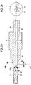
- Fig. 2A is a sectional view of a drive shaft
- Fig. 2B is a right-side view of the drive shaft
- Figs. 3 and 4 are sectional views taken along line a-a of Fig. 2A .
- the open-type compressor 1 includes a tubular housing 2 in which a bottomed front housing 3 and a bottomed rear housing 4 are integrally connected to each other by a bolt 5.
- a bearing member 6 is fixed and installed to the opening end side in the housing 2 on the front housing 3 side by a bolt 7, and a drive shaft 9 is rotatably supported by a radial bearing portion 6A of the bearing member 6 and a rolling bearing 8 which is installed in the front housing 3.
- One end of the drive shaft 9 penetrates the front housing 3 and protrudes outside the front housing 3, and driving power from an external drive source such as an engine is input to the protrusion portion of the drive shaft 9 via a pulley 10 and an electromagnetic clutch 11.
- the pulley 10 is rotatably supported to an outer circumference of a flange member 13, which is fixed and installed to the front end surface of the front housing 3 by a bolt 12, via a rolling bearing 14, and a coil assembly 15 of the electromagnetic clutch 11 is incorporated into the pulley 10.
- an armature assembly 16 of the electromagnetic clutch 11 is assembled to the external protrusion end of the drive shaft 9 by a bolt 17 via a boss portion so as to face the pulley 10.
- a mechanical seal 18 for hermetically sealing the penetration portion of the drive shaft 9 is installed on the inner circumference of the flange member 13.
- a compression mechanism 19 is incorporated into the rear housing 4 side of the housing 2.
- the compression mechanism 19 is a scroll compression mechanism 19 which includes a pair of fixed scroll 20 and orbiting scroll 21.
- the pair of fixed scroll 20 and orbiting scroll 21 engage with each other so as to be deviated by a phase of 180°, multiple compression chambers 22 are formed between both scrolls 20 and 21, and the scroll compression mechanism 19 is known.
- the fixed scroll 20 is fastened and fixed to the bearing member 6 by a bolt 23, and a discharge cavity 26 is formed between the back face of the end plate of the fixed scroll and the inner surface of the rear housing 4.
- a discharge port 24 which discharges compressed gas into the discharge cavity 26 and a discharge valve 25 which opens and closes the discharge port 24 are provided on the end plate of the fixed scroll 20.
- a discharge port 27 through which compressed gas which has been discharged into the discharge cavity 26 is discharged to the outside is open to the rear housing 4, and a discharge pipe configuring a refrigerating cycle can be connected to the rear housing 4.
- the orbiting scroll 21 has a boss portion 28 on the back face of the end plate of the orbiting scroll 21, a crank pin 9A provided on the inner end side of the drive shaft 9 is connected to the boss portion 28 via a drive bush 29 and a turning bearing 30, and the orbiting scroll 21 is pivotally driven via the crank pin 9A by the rotation of the drive shaft 9.
- the back face of the end plate of the orbiting scroll 21 is supported by a thrust bearing 31 provided in the bearing member 6, the rotation of the orbiting scroll 21 is prevented by a known rotation prevention mechanism 32 including an oldham link, a pin ring, or the like which is interposed between the back plate of the end plate and the bearing member 6, and the orbiting scroll 21 is driven so as to be pivotally revolved with respect to the fixed scroll 20.
- the compression mechanism 19 is a so-called stepped scroll compression mechanism 19 in which a step portion which changes a lap height is provided in spiral directions of the fixed scroll 20 and the orbiting scroll 21, the outer circumferential side lap height is higher than the inner circumferential side lap height, gas can be compressed not only in the circumferential direction but also in the axial direction, and a three-dimensional compression can be realized.
- the present invention is not limited to this.
- the inside of the front housing 3 is filled with a lubricant having a required amount, the lower space inside the front housing 3 becomes an oil sump 35, and oil is collected in the oil sump 35.
- the oil in the oil sump 35 is suctioned to an oil supply pump 37 via an intake passage 36.
- the oil supply pump 37 is a known a rotary-type displacement pump in which a decentered portion 9B ( Fig. 2 ) is formed on the outer circumferential section of the drive shaft 9 penetrating the front end surface of the front housing 3, and a rotor 38 which is rotated so as to be decentered in the cylinder formed between the front end surface of the front housing 3 and the end surface of the flange member 13 is fitted to the decentered portion 9B.
- the oil which is pumped up from the oil sump 35 by the oil supply pump 37 is discharged into a pump chamber 39 which is formed between the decentered portion 9B around the drive shaft 9 and the mechanical seal 18.
- the oil pumped to the pump chamber 39 is supplied to a sliding part such as the radial bearing portion 6A, the drive bush 29, the turning bearing 30, or the thrust bearing 31, a sliding part such as the mechanical seal 18, or the like through a radial-direction oil supply passage 40 and an axial-direction oil supply passage 41 which are provided inside the drive shaft 9.
- the axial-direction oil supply passage 41 which is provided along the axis L of the drive shaft 9 is inside the drive shaft 9 at a position decentered to an axis L of the drive shaft 9 by a predetermined dimension (decentered dimension) ⁇ h.
- the radial-direction oil supply passage 40 through which the oil inside the pump chamber 39 is introduced to the axial-direction oil supply passage 41 is provided in the decentered direction of the axial-direction oil supply passage 41.
- the radial-direction oil supply passage 40 is provided at the position at which a passage length h1 thereof is shortest on the axis in the decentered direction.
- a radial-direction oil supply passage 40A may be provided in a direction which has a predetermined angle with respect to the axis in the decentered direction.
- a passage length h2 of the radial-direction oil supply passage 40A can be shorter than the passage length h with which the axial-direction oil supply passage 41 is provided on the axis L of the drive shaft 9, and in this case, the passage h2 satisfies that h1 ⁇ h2 ⁇ h.
- the radial-direction oil supply passage through which the oil in the pump chamber 39 is introduced to the axial-direction oil supply passage 41 is not limited to be positioned on the axis in the decentered direction, the radial-direction oil supply passage is provided on the decentered side of the axial-direction oil supply passage 41, and the passage length of the radial-direction oil supply passage can be shorter than that when the axial-direction oil supply passage 41 is provided on the axis L of the drive shaft 9.
- the axial-direction oil supply passage 41 is a blind hole which is pierced along the axis L from one end of the crank pin 9A.
- the radial-direction oil supply passages 40 and 40A are hole which are provided to be radially perpendicular in the vicinity of the tip portion of the blind hole, and it is necessary to prevent steps, burrs, or the like generating flow-path pressure loss from occurring in the intersection portion (connection portion) between the axial-direction oil supply passage 41 and the radial-direction oil supply passages 40 and 40A.
- a passage diameter d1 of the axial-direction oil supply passage 41 to be greater than a passage diameter d2 of each of the radial-direction oil supply passages 40 and 40A (d1 > d2), it is possible to easily obtain centrifugal pump effect due to decentering in the axial-direction oil supply passage 41 and to decrease the flow-path pressure loss in the passage, and both passages 40 and 40A, and 41 can be processed to communicate with each other such that steps, burrs, and the like do not occur in the connection portion between both passages 40 an 40A, and 41.
- the orbiting scroll 21 of the scroll compression mechanism 19 is driven so as to be pivotally revolved around the fixed scroll 20
- low-pressure gas suctioned from the intake port 33 into the intake cavity 34 is suctioned into the compression chamber 22 and is compressed so as to be high-pressure gas
- the high-pressure gas is discharged from the discharge port 24 into the discharge cavity 26 and discharged from the discharge port 27 to the refrigerating cycle.
- a lubricant in the oil sump 35 is suctioned via the intake passage 36 by the oil supply pump 37 driven by the rotation of the drive shaft 9, and is pumped to the pump chamber 39.
- the oil pumped into the pump chamber 39 lubricates the sliding part of the mechanical seal 18, is introduced into the axial-direction oil supply passage 41 via the radial-direction oil supply passages 40 and 40A, and is supplied to the sliding part such as the radial bearing portion 6A, the drive bush 29, the turning bearing 30, or the thrust bearing 31 through the axial-direction oil supply passage 41 so as to lubricate the sliding part.
- the oil which has lubricated the sliding part is collected in the oil sump 35 which is the bottom portion of the housing 2 and is recirculated.
- the axial-direction oil supply passage 41 is provided at the position which is decentered to the axis L of the drive shaft 9 by the predetermined dimension ⁇ h, and the radial-direction oil supply passages 40 and 40A through which the oil in the pump chamber 39 is introduced to the axial-direction oil supply passage 41 is introduced are provided on the decentered side of the axial-direction oil supply passage 41. Accordingly, the passage lengths h1 and h2 can be shorter than those in the case where the axial-direction oil supply passage 41 is provided on the axis L of the drive shaft 9 (h1 ⁇ h2 ⁇ h).
- the passage lengths h1 and h2 of the radial-direction oil supply passages 40 and 40A can be shortened by the dimension ⁇ h by which the axial-direction oil supply passage 41 is decentered, and it is possible to decrease the flow-path pressure loss due to the centrifugal force generated in the inlet portions of the radial-direction oil supply passages 40 and 40A.
- the axial-direction oil supply passage 41 is decentered by the predetermined dimension ⁇ h, it is possible to increase oil supply performance with respect to the sliding part using centrifugal pump effects acting on the oil in the axial-direction oil supply passage 41.
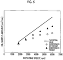
- Fig. 5 is a graph showing oil supply characteristics in the case where the forcible oil-supply type compressor is adopted, in which a horizontal axis indicates a rotating speed (rpm) of the drive shaft 9 and a vertical axis indicates an oil supply amount (cm 3 /min).
- a horizontal axis indicates a rotating speed (rpm) of the drive shaft 9
- a vertical axis indicates an oil supply amount (cm 3 /min).
- the axial-direction oil supply passage 41 is provided so as to be decentered to the axis L
- the radial-direction oil supply passages 40 and 40A are provided on the decentered side, and the passage lengths h1 and h2 are shortened, the oil supply amount is improved in the high rotational speed range as shown by plots ⁇ and can approach the theoretical value.
- the radial-direction oil supply passage 40 is provided at the position at which the passage length h1 is shortest on the axis in the decentered direction. Accordingly, the passage length h1 of the radial-direction oil supply passage 40 can be decreased by the degree corresponding to the decentered dimension ⁇ h of the axial-direction oil supply passage 41, and the passage length h1 becomes the shortest length. Therefore, it is possible to minimize the flow-path pressure loss due to the centrifugal force generated in the inlet portion of the radial-direction oil supply passage 40. Accordingly, it is possible to improve the oil supply amount in the high rotational speed range and to further improve the oil supply performance.
- the open-type compressor 1 according to the present embodiment is applied to an open-type scroll compressor 1 which adopts the forcible oil-supply type compressor which is operated at a high speed of 3600 rpm or more, it is possible to improve lubrication performance.
- the present invention is not limited to the invention according to the present embodiment, and may be appropriately modified.
- the open-type compressor 1 the example in which the scroll type compressor is applied is described.
- other-type compressors for example, a rotary open-type compressor, a swash plate open-type compressor, a reciprocating open-type compressor, or the like may be similarly applied.
- the present invention is not limited to this, and other type oil supply pumps such as a screw type pump may be applied.
Landscapes
- Engineering & Computer Science (AREA)
- Mechanical Engineering (AREA)
- General Engineering & Computer Science (AREA)
- Applications Or Details Of Rotary Compressors (AREA)
- Compressor (AREA)
- Rotary Pumps (AREA)
Abstract
Description
- The present invention relates to an open-type compressor which is provided on an outer circumference of a drive shaft and can supply oil which is pumped up by an oil supply pump driven by the drive shaft to a sliding part through an oil supply passage which is pierced inside the drive shaft along an axial direction.
- In a horizontally laid open-type compressor in which one end of a drive shaft rotatably supported inside a housing via a bearing protrudes outside the housing and which is driven by driving power from the outside, in a case where a forcible oil-supply type compressor which pumps a lubricant in an oil sump by an oil supply pump and supplies the oil to a sliding part such as a bearing so as to lubricate the sliding part is adopted, as described in Patent Document 1, the oil supply pump which is driven by the drive shaft is provided on the outer circumference of the drive shaft, and oil pumped up by the oil supply pump is supplied to the sliding part through an oil supply passage which is pierced inside the drive shaft along the axial direction.
- In a case of a closed-type compressor, in both a vertically laid closed-type compressor and a horizontally laid closed-type compressor, in general, a centrifugal-type oil supply pump, a displacement-type oil supply pump, or the like is provided on the end of a drive shaft, a lubricant which fills a sealed vessel is pumped up by the oil supply pump, and the oil is supplied to a sliding part through an oil supply passage which is pierced inside the drive shaft along the axial direction. Regarding forcible oil-supply type compressors, Patent Document 2 discloses a forcible oil-supply type compressor in which the oil supply passage pierced inside the drive shaft along the axial direction is provided so as to be offset with respect to the axis by a predetermined dimension and oil supply performance is improved using a centrifugal force.
-
- [PTL 1]
Japanese Unexamined Patent Application Publication No. 2005-282446 - [PTL 2]
Japanese Unexamined Patent Application Publication No. 8-219063 - As described above, in the case where a forcible oil-supply type compressor is adopted, when the compressor is a closed-type compressor, external driving power is not required, and the oil supply passage can be pierced in the axial direction in a state where one end of the drive shaft is an open end. Accordingly, it is possible to increase a rotating speed or a centrifugal force of the oil supply pump in proportion to the rotating speed of the drive shaft without it being easily influenced by the centrifugal force. Therefore, since an oil supply amount increases and oil supply performance can be improved, significant problems do not occur in the closed-type compressor. However, in a case of an open-type compressor, external driving power is required, and it is difficult to set one end of the drive shaft to an open end. Accordingly, it is necessary to temporarily discharge oil pumped up by the oil supply pump to a pump chamber formed around the drive shaft, and to supply the oil to an oil supply passage which is pierced in the axial direction through an oil supply passage which is provided from the pump chamber to the drive shaft in a radial direction.
- Therefore, it is not possible to prevent pressure loss due to a centrifugal force from occurring in an inlet portion of the oil supply passage which is structurally pierced in the radial direction. Since the flow-path pressure loss is likely to increase as the rotating speed of the drive shaft increases, in a case where an axial-direction oil supply passage is provided on the axis of the drive shaft (decentering is not present), as shown in
Fig. 3 , the oil supply amount decreases particularly in a high rotational speed range. - The present invention is made in consideration of the above-described circumstances, and an object thereof is to provide an open-type compressor in which a decrease in the oil supply amount due to an increase of the flow-path pressure loss can be prevented particularly in the high rotational speed range, and reliability with respect to lubrication performance can be improved.
- According to a first aspect of the present invention, there is provided an open-type compressor, including: a drive shaft which is rotatably supported inside a housing and includes one end which protrudes outside the housing; an oil supply pump which is provided on an outer circumferential section of the drive shaft and is driven by rotation of the drive shaft; a pump chamber which is formed around the drive shaft and into which oil pumped up by the oil supply pump is discharged; an axial-direction oil supply passage which is pierced inside the drive shaft along the direction of an axis of the axial-direction oil supply passage, and through which oil from the pump chamber is supplied to a sliding part; and a radial-direction oil supply passage which is provided in the drive shaft and through which oil in the pump chamber is introduced to the axial-direction oil supply passage, in which the axial-direction oil supply passage is provided at a position which is decentered by a predetermined dimension with respect to the axis of the drive shaft, and the radial-direction oil supply passage is provided on a side toward which the axial-direction oil supply passage is decentered.
- According to the first aspect, the axial-direction oil supply passage which is pierced inside the drive shaft is provided at the position decentered by a predetermined dimension with respect to the axis of the drive shaft, and the radial-direction oil supply passage through which oil in the pump chamber pumped up by the oil supply pump is introduced to the axial-direction oil supply passage is provided in the direction in which the axial-direction oil supply passage is decentered. Accordingly, the passage length of the radial-direction oil supply passage decreases as the axial-direction oil supply passage is decentered and the radial-direction oil supply passage is provided on the decentered side, and it is possible to decrease flow-path pressure loss due to a centrifugal force generated in an inlet portion of the radial-direction oil supply passage. That is, the passage length of the radial-direction oil supply passage becomes the radius of the drive shaft if the axial-direction oil supply passage is not decentered. However, in the case where the radial-direction oil supply passage is provided on the side toward which the axial-direction oil supply passage is decentered, the passage length can be shorter than the radius of the drive shaft, and it is possible to decrease the flow-path pressure loss according to the decrease in the passage length. In addition, the axial-direction oil supply passage is decentered by the predetermined dimension, and it is possible to increase oil supply performance with respect to the sliding part using centrifugal pump effects acting on the oil in the axial-direction oil supply passage. Therefore, according to synergistic effects between the decreasement in the flow-path pressure loss in the radial-direction oil supply passage and the improvement in oil supply performance in the axial-direction oil supply passage, it is possible to prevent the oil supply amount from decreasing particularly in a high rotational speed range, and it is possible to increase reliability with respect to lubrication performance.
- In the open-type compressor of the first aspect of the present invention, the radial-direction oil supply passage may be provided at a position at which a passage length is shortest on the axis in the decentered direction.
- According to the first aspect of the present invention, since the radial-direction oil supply passage is provided at the position at which the passage length is shortest on the axis in the decentered direction, the passage length of the radial-direction oil supply passage can be decreased by the degree corresponding to the decentered dimension of the axial-direction oil supply passage, and the passage length becomes the shortest length. Therefore, it is possible to minimize the flow-path pressure loss due to the centrifugal force generated in the inlet portion of the radial-direction oil supply passage. Accordingly, it is possible to improve the oil supply amount in the high rotational speed range and to further improve the oil supply performance.
- In the above-described open-type compressors of the first aspect of the present invention, a passage diameter of the axial-direction oil supply passage may be greater than a passage diameter of the radial-direction oil supply passage.
- According to the first aspect, since the passage diameter of the axial-direction oil supply passage is greater than the passage diameter of the radial-direction oil supply passage, it is possible to easily obtain centrifugal pump effects due to decentering and to decrease the flow-path pressure loss in the passage. In addition, by processing a connection between the radial-direction oil supply passage and the axial-direction oil supply passage such that these communicate with each other such that steps, burrs, and the like do not occur, it is possible to prevent flow-path pressure loss from occurring in the connection portion between the radial-direction oil supply passage and the axial-direction oil supply passage, and it is possible to prevent the oil supply amount from decreasing in the high rotational speed range and to improve the oil supply performance.
- According to the present invention, the passage length of the radial-direction oil supply passage decreases as the axial-direction oil supply passage is decentered and the radial-direction oil supply passage is provided on the decentered side, and it is possible to decrease flow-path pressure loss due to a centrifugal force generated in the inlet portion of the radial-direction oil supply passage. In addition, since the axial-direction oil supply passage is decentered by the predetermined dimension, and it is possible to increase oil supply performance with respect to the sliding part using centrifugal pump effects acting on the oil in the axial-direction oil supply passage, according to synergistic effects between the decreasement in the flow-path pressure loss in the radial-direction oil supply passage and the improvement of oil supply performance in the axial-direction oil supply passage, it is possible to prevent the oil supply amount from decreasing particularly in a high rotational speed range, and it is possible to increase reliability with respect to lubrication performance.
-
-
Fig. 1 is a longitudinal sectional view of an open-type compressor according to an embodiment of the present invention. -
Fig. 2A is a sectional view of a drive shaft in the open-type compressor, andFig. 2B is a right-side view of the drive shaft. -
Fig. 3 is a sectional view taken along line a-a ofFig. 2A . -
Fig. 4 is a sectional view corresponding toFig. 3 of a modification example of a radial-direction oil supply passage provided in the drive shaft. -
Fig. 5 is a graph showing oil supply characteristics in the open-type compressor. - Hereinafter, an embodiment of the present invention will be described with reference to
Figs. 1 to 5 . -
Fig. 1 is a longitudinal sectional view of an open-type compressor according to the embodiment of the present invention,Fig. 2A is a sectional view of a drive shaft,Fig. 2B is a right-side view of the drive shaft, andFigs. 3 and 4 are sectional views taken along line a-a ofFig. 2A . - The open-type compressor 1 includes a tubular housing 2 in which a bottomed front housing 3 and a bottomed
rear housing 4 are integrally connected to each other by a bolt 5. - A bearing member 6 is fixed and installed to the opening end side in the housing 2 on the front housing 3 side by a bolt 7, and a
drive shaft 9 is rotatably supported by a radial bearingportion 6A of the bearing member 6 and a rollingbearing 8 which is installed in the front housing 3. One end of thedrive shaft 9 penetrates the front housing 3 and protrudes outside the front housing 3, and driving power from an external drive source such as an engine is input to the protrusion portion of thedrive shaft 9 via apulley 10 and anelectromagnetic clutch 11. - The
pulley 10 is rotatably supported to an outer circumference of aflange member 13, which is fixed and installed to the front end surface of the front housing 3 by abolt 12, via a rollingbearing 14, and acoil assembly 15 of theelectromagnetic clutch 11 is incorporated into thepulley 10. In addition, anarmature assembly 16 of theelectromagnetic clutch 11 is assembled to the external protrusion end of thedrive shaft 9 by abolt 17 via a boss portion so as to face thepulley 10. In addition, amechanical seal 18 for hermetically sealing the penetration portion of thedrive shaft 9 is installed on the inner circumference of theflange member 13. - A
compression mechanism 19 is incorporated into therear housing 4 side of the housing 2. Here, thecompression mechanism 19 is ascroll compression mechanism 19 which includes a pair offixed scroll 20 and orbitingscroll 21. In thescroll compression mechanism 19, the pair offixed scroll 20 and orbitingscroll 21 engage with each other so as to be deviated by a phase of 180°,multiple compression chambers 22 are formed between bothscrolls scroll compression mechanism 19 is known. - The
fixed scroll 20 is fastened and fixed to the bearing member 6 by abolt 23, and adischarge cavity 26 is formed between the back face of the end plate of the fixed scroll and the inner surface of therear housing 4. Adischarge port 24 which discharges compressed gas into thedischarge cavity 26 and adischarge valve 25 which opens and closes thedischarge port 24 are provided on the end plate of thefixed scroll 20. In addition, adischarge port 27 through which compressed gas which has been discharged into thedischarge cavity 26 is discharged to the outside is open to therear housing 4, and a discharge pipe configuring a refrigerating cycle can be connected to therear housing 4. - The orbiting
scroll 21 has aboss portion 28 on the back face of the end plate of theorbiting scroll 21, acrank pin 9A provided on the inner end side of thedrive shaft 9 is connected to theboss portion 28 via adrive bush 29 and a turning bearing 30, and the orbitingscroll 21 is pivotally driven via thecrank pin 9A by the rotation of thedrive shaft 9. In addition, the back face of the end plate of the orbitingscroll 21 is supported by a thrust bearing 31 provided in the bearing member 6, the rotation of the orbitingscroll 21 is prevented by a knownrotation prevention mechanism 32 including an oldham link, a pin ring, or the like which is interposed between the back plate of the end plate and the bearing member 6, and theorbiting scroll 21 is driven so as to be pivotally revolved with respect to thefixed scroll 20. - An
intake port 33 which is connected to an intake pipe on the refrigerating cycle side is provided on the outer circumference on the front end side of therear housing 4, and the compressed gas entering from theintake port 33 into anintake cavity 34 is suctioned to thecompression chamber 22 of thescroll compression mechanism 19 so as to be compressed. In the present embodiment, thecompression mechanism 19 is a so-called steppedscroll compression mechanism 19 in which a step portion which changes a lap height is provided in spiral directions of the fixedscroll 20 and the orbitingscroll 21, the outer circumferential side lap height is higher than the inner circumferential side lap height, gas can be compressed not only in the circumferential direction but also in the axial direction, and a three-dimensional compression can be realized. However, the present invention is not limited to this. - Meanwhile, the inside of the front housing 3 is filled with a lubricant having a required amount, the lower space inside the front housing 3 becomes an
oil sump 35, and oil is collected in theoil sump 35. The oil in theoil sump 35 is suctioned to anoil supply pump 37 via anintake passage 36. - The
oil supply pump 37 is a known a rotary-type displacement pump in which a decenteredportion 9B (Fig. 2 ) is formed on the outer circumferential section of thedrive shaft 9 penetrating the front end surface of the front housing 3, and arotor 38 which is rotated so as to be decentered in the cylinder formed between the front end surface of the front housing 3 and the end surface of theflange member 13 is fitted to the decenteredportion 9B. - The oil which is pumped up from the
oil sump 35 by theoil supply pump 37 is discharged into apump chamber 39 which is formed between thedecentered portion 9B around thedrive shaft 9 and themechanical seal 18. The oil pumped to thepump chamber 39 is supplied to a sliding part such as theradial bearing portion 6A, thedrive bush 29, the turningbearing 30, or thethrust bearing 31, a sliding part such as themechanical seal 18, or the like through a radial-directionoil supply passage 40 and an axial-directionoil supply passage 41 which are provided inside thedrive shaft 9. - As shown in
Figs. 2 and3 , the axial-directionoil supply passage 41 which is provided along the axis L of thedrive shaft 9 is inside thedrive shaft 9 at a position decentered to an axis L of thedrive shaft 9 by a predetermined dimension (decentered dimension) Δh. In addition, the radial-directionoil supply passage 40 through which the oil inside thepump chamber 39 is introduced to the axial-directionoil supply passage 41 is provided in the decentered direction of the axial-directionoil supply passage 41. In the present embodiment, the radial-directionoil supply passage 40 is provided at the position at which a passage length h1 thereof is shortest on the axis in the decentered direction. Accordingly, compared to a passage length h with which the axial-directionoil supply passage 41 is provided on the axis L of thedrive shaft 9, the passage length h1 of the radial-directionoil supply passage 40 can be shortened by Δh (Δh = h - h1). - However, the present invention is not limited to the above-described case where the radial-direction
oil supply passage 40 is provided on the axis of the decentered direction and the passage length h1 is shortest. That is, as shown inFig. 4 , a radial-directionoil supply passage 40A may be provided in a direction which has a predetermined angle with respect to the axis in the decentered direction. According to this configuration, a passage length h2 of the radial-directionoil supply passage 40A can be shorter than the passage length h with which the axial-directionoil supply passage 41 is provided on the axis L of thedrive shaft 9, and in this case, the passage h2 satisfies that h1 < h2 < h. That is, the radial-direction oil supply passage through which the oil in thepump chamber 39 is introduced to the axial-directionoil supply passage 41 is not limited to be positioned on the axis in the decentered direction, the radial-direction oil supply passage is provided on the decentered side of the axial-directionoil supply passage 41, and the passage length of the radial-direction oil supply passage can be shorter than that when the axial-directionoil supply passage 41 is provided on the axis L of thedrive shaft 9. - In addition, as described above, according to the case where the axial-direction
oil supply passage 41 and the radial-directionoil supply passages oil supply passage 41 is a blind hole which is pierced along the axis L from one end of thecrank pin 9A. Meanwhile, the radial-directionoil supply passages oil supply passage 41 and the radial-directionoil supply passages oil supply passage 41 to be greater than a passage diameter d2 of each of the radial-directionoil supply passages oil supply passage 41 and to decrease the flow-path pressure loss in the passage, and bothpassages passages 40 an 40A, and 41. - According to the above-described configuration, the following effects of the present embodiment are exerted.
- In the open-type compressor 1, if the
electromagnetic clutch 11 is turned on, the driving power input from the external drive source via thepulley 10 is transmitted to thedrive shaft 9, and thedrive shaft 9 is rotationally driven. Accordingly, the orbitingscroll 21 of thescroll compression mechanism 19 is driven so as to be pivotally revolved around the fixedscroll 20, low-pressure gas suctioned from theintake port 33 into theintake cavity 34 is suctioned into thecompression chamber 22 and is compressed so as to be high-pressure gas, and the high-pressure gas is discharged from thedischarge port 24 into thedischarge cavity 26 and discharged from thedischarge port 27 to the refrigerating cycle. - During this, a lubricant in the
oil sump 35 is suctioned via theintake passage 36 by theoil supply pump 37 driven by the rotation of thedrive shaft 9, and is pumped to thepump chamber 39. The oil pumped into thepump chamber 39 lubricates the sliding part of themechanical seal 18, is introduced into the axial-directionoil supply passage 41 via the radial-directionoil supply passages radial bearing portion 6A, thedrive bush 29, the turningbearing 30, or the thrust bearing 31 through the axial-directionoil supply passage 41 so as to lubricate the sliding part. The oil which has lubricated the sliding part is collected in theoil sump 35 which is the bottom portion of the housing 2 and is recirculated. - Here, in the present embodiment, the axial-direction
oil supply passage 41 is provided at the position which is decentered to the axis L of thedrive shaft 9 by the predetermined dimension Δh, and the radial-directionoil supply passages pump chamber 39 is introduced to the axial-directionoil supply passage 41 is introduced are provided on the decentered side of the axial-directionoil supply passage 41. Accordingly, the passage lengths h1 and h2 can be shorter than those in the case where the axial-directionoil supply passage 41 is provided on the axis L of the drive shaft 9 (h1 < h2 < h). - Accordingly, the passage lengths h1 and h2 of the radial-direction
oil supply passages oil supply passage 41 is decentered, and it is possible to decrease the flow-path pressure loss due to the centrifugal force generated in the inlet portions of the radial-directionoil supply passages oil supply passage 41 is decentered by the predetermined dimension Δh, it is possible to increase oil supply performance with respect to the sliding part using centrifugal pump effects acting on the oil in the axial-directionoil supply passage 41. -
Fig. 5 is a graph showing oil supply characteristics in the case where the forcible oil-supply type compressor is adopted, in which a horizontal axis indicates a rotating speed (rpm) of thedrive shaft 9 and a vertical axis indicates an oil supply amount (cm3/min). With respect to a theoretical value indicated by a solid line, since the passage length h of the radial-direction oil supply passage is lengthened in the case where the axial-directionoil supply passage 41 is provided on the axis L, the oil supply amount with respect to the theoretical value decreases in a high rotational speed range as shown by plots. Like the present embodiment, in the case the axial-directionoil supply passage 41 is provided so as to be decentered to the axis L, the radial-directionoil supply passages - Therefore, in the present embodiment, according to synergistic effects between the decreasement in the flow-path pressure loss in the radial-direction
oil supply passages oil supply passage 41, it is possible to prevent the oil supply amount from decreasing in the high rotational speed range, and it is possible to increase reliability with respect to lubrication performance. - Particularly, the radial-direction
oil supply passage 40 is provided at the position at which the passage length h1 is shortest on the axis in the decentered direction. Accordingly, the passage length h1 of the radial-directionoil supply passage 40 can be decreased by the degree corresponding to the decentered dimension Δh of the axial-directionoil supply passage 41, and the passage length h1 becomes the shortest length. Therefore, it is possible to minimize the flow-path pressure loss due to the centrifugal force generated in the inlet portion of the radial-directionoil supply passage 40. Accordingly, it is possible to improve the oil supply amount in the high rotational speed range and to further improve the oil supply performance. - In addition, in the radial-direction
oil supply passages oil supply passage 41, since the passage diameter d1 of the axial-directionoil supply passage 41 is greater than the passage diameter d2 of each of the radial-directionoil supply passages oil supply passage 41 and to decrease the flow-path pressure loss in the passage. In addition, by processing a connection between the radial-directionoil supply passages oil supply passage 41 so as to communicate with each other such that steps, burrs, and the like do not occur, it is possible to prevent the flow-path pressure loss from occurring in the connection portion between the radial-directionoil supply passages oil supply passage 41, and it is possible to prevent the oil supply amount from decreasing in the high rotational speed range due to synergistic effects and to improve the oil supply performance. - Particularly, in a case where the open-type compressor 1 according to the present embodiment is applied to an open-type scroll compressor 1 which adopts the forcible oil-supply type compressor which is operated at a high speed of 3600 rpm or more, it is possible to improve lubrication performance.
- In addition, the present invention is not limited to the invention according to the present embodiment, and may be appropriately modified. For example, in the above-described embodiment, as an example of the open-type compressor 1, the example in which the scroll type compressor is applied is described. However, other-type compressors, for example, a rotary open-type compressor, a swash plate open-type compressor, a reciprocating open-type compressor, or the like may be similarly applied.
- In addition, in the above-described embodiment, the example in which the rotary displacement-type pump is applied as the
oil supply pump 37 is described. However, the present invention is not limited to this, and other type oil supply pumps such as a screw type pump may be applied. -
- 1: open-type compressor
- 2: housing
- 9: drive shaft
- 37: oil supply pump
- 39: pump chamber
- 40, 40A: radial-direction oil supply passage
- 41: axial-direction oil supply passage
- L: axis of drive shaft
- Δh: decentered dimension
- h1, h2: passage length of radial-direction oil supply passage
- d1: passage diameter of axial-direction oil supply passage
- d2: passage diameter of radial-direction oil supply passage
Claims (3)
- An open-type compressor, comprising:a drive shaft which is rotatably supported inside a housing and includes one end which protrudes outside the housing;an oil supply pump which is provided on an outer circumferential section of the drive shaft and is driven by rotation of the drive shaft;a pump chamber which is formed around the drive shaft and from which oil pumped up by the oil supply pump is discharged;an axial-direction oil supply passage which is pierced inside the drive shaft along the direction of an axis of the axial-direction oil supply passage, and through which oil from the pump chamber is supplied to a sliding part; anda radial-direction oil supply passage which is provided in the drive shaft and through which oil in the pump chamber is introduced to the axial-direction oil supply passage,wherein the axial-direction oil supply passage is provided at a position which is decentered by a predetermined dimension with respect to the axis of the drive shaft, andwherein the radial-direction oil supply passage is provided on a side toward which the axial-direction oil supply passage is decentered.
- The open-type compressor according to claim 1,
wherein the radial-direction oil supply passage is provided at a position at which a passage length is shortest on the axis in the decentered direction. - The open-type compressor according to claim 1,
wherein a passage diameter of the axial-direction oil supply passage is greater than a passage diameter of the radial-direction oil supply passage.
Applications Claiming Priority (2)
| Application Number | Priority Date | Filing Date | Title |
|---|---|---|---|
| JP2014162441A JP6462265B2 (en) | 2014-08-08 | 2014-08-08 | Open type compressor |
| PCT/JP2015/072069 WO2016021590A1 (en) | 2014-08-08 | 2015-08-04 | Open-type compressor |
Publications (3)
| Publication Number | Publication Date |
|---|---|
| EP3150855A1 true EP3150855A1 (en) | 2017-04-05 |
| EP3150855A4 EP3150855A4 (en) | 2017-06-28 |
| EP3150855B1 EP3150855B1 (en) | 2020-04-22 |
Family
ID=55263852
Family Applications (1)
| Application Number | Title | Priority Date | Filing Date |
|---|---|---|---|
| EP15829255.7A Active EP3150855B1 (en) | 2014-08-08 | 2015-08-04 | Open-type compressor |
Country Status (6)
| Country | Link |
|---|---|
| EP (1) | EP3150855B1 (en) |
| JP (1) | JP6462265B2 (en) |
| KR (2) | KR20180112091A (en) |
| CN (1) | CN106662093A (en) |
| AU (1) | AU2015300143B2 (en) |
| WO (1) | WO2016021590A1 (en) |
Family Cites Families (7)
| Publication number | Priority date | Publication date | Assignee | Title |
|---|---|---|---|---|
| JPH04279792A (en) * | 1991-03-08 | 1992-10-05 | Toshiba Corp | Fluid compressor |
| JPH05149277A (en) * | 1991-11-26 | 1993-06-15 | Mitsubishi Heavy Ind Ltd | Horizontal type closed scroll compressor |
| JPH08219063A (en) | 1995-02-13 | 1996-08-27 | Daikin Ind Ltd | Lubricating oil supply structure for rotating shaft |
| CN2688935Y (en) * | 2004-01-21 | 2005-03-30 | 柳州高新区浦发汽车空调有限公司 | Volumetric vortex fluid compressor |
| JP4301985B2 (en) * | 2004-03-29 | 2009-07-22 | 三菱重工業株式会社 | Scroll compressor |
| JP2012097577A (en) * | 2010-10-29 | 2012-05-24 | Daikin Industries Ltd | Compressor |
| CN202520559U (en) * | 2012-03-14 | 2012-11-07 | 广东美芝精密制造有限公司 | Crankshaft structure of rolling rotor compressor |
-
2014
- 2014-08-08 JP JP2014162441A patent/JP6462265B2/en active Active
-
2015
- 2015-08-04 AU AU2015300143A patent/AU2015300143B2/en active Active
- 2015-08-04 CN CN201580033419.XA patent/CN106662093A/en active Pending
- 2015-08-04 EP EP15829255.7A patent/EP3150855B1/en active Active
- 2015-08-04 KR KR1020187028281A patent/KR20180112091A/en not_active Withdrawn
- 2015-08-04 WO PCT/JP2015/072069 patent/WO2016021590A1/en not_active Ceased
- 2015-08-04 KR KR1020167036107A patent/KR102096139B1/en active Active
Also Published As
| Publication number | Publication date |
|---|---|
| KR20170010406A (en) | 2017-01-31 |
| WO2016021590A1 (en) | 2016-02-11 |
| EP3150855A4 (en) | 2017-06-28 |
| JP2016037922A (en) | 2016-03-22 |
| KR20180112091A (en) | 2018-10-11 |
| AU2015300143A1 (en) | 2017-01-19 |
| JP6462265B2 (en) | 2019-01-30 |
| CN106662093A (en) | 2017-05-10 |
| AU2015300143B2 (en) | 2018-05-10 |
| KR102096139B1 (en) | 2020-04-01 |
| EP3150855B1 (en) | 2020-04-22 |
Similar Documents
| Publication | Publication Date | Title |
|---|---|---|
| EP2863059B1 (en) | Scroll compression device | |
| EP2913531B1 (en) | Scroll compressor with balance weight | |
| US8747088B2 (en) | Open drive scroll compressor with lubrication system | |
| WO2012144067A1 (en) | Scroll compressor | |
| US20140023538A1 (en) | Vane rotary compressor | |
| JP6554926B2 (en) | Scroll compressor | |
| CN108350869B (en) | Fluid machinery | |
| JP2008240597A (en) | Variable crank mechanism and scroll fluid machine equipped with variable crank mechanism | |
| JP2012219654A (en) | Rotary fluid machine | |
| US9322403B2 (en) | Compressor | |
| EP2918773A1 (en) | Rotary compressor | |
| EP3388673A1 (en) | Scroll compressor | |
| EP3150855B1 (en) | Open-type compressor | |
| WO2016125228A1 (en) | Compressor | |
| JP6906887B2 (en) | Scroll fluid machine | |
| JP2013060899A (en) | Compressor | |
| JP6207828B2 (en) | Scroll compressor | |
| JP5999922B2 (en) | Scroll compressor | |
| EP2960513B1 (en) | Hermetic compressor | |
| EP3315781B1 (en) | Open type compressor | |
| US12018685B2 (en) | Scroll compressor provided with an hydrostatic lower bearing arrangement | |
| JP5764715B2 (en) | Scroll compressor | |
| JP2019056336A (en) | Scroll type fluid machine |
Legal Events
| Date | Code | Title | Description |
|---|---|---|---|
| STAA | Information on the status of an ep patent application or granted ep patent |
Free format text: STATUS: THE INTERNATIONAL PUBLICATION HAS BEEN MADE |
|
| PUAI | Public reference made under article 153(3) epc to a published international application that has entered the european phase |
Free format text: ORIGINAL CODE: 0009012 |
|
| STAA | Information on the status of an ep patent application or granted ep patent |
Free format text: STATUS: REQUEST FOR EXAMINATION WAS MADE |
|
| 17P | Request for examination filed |
Effective date: 20161226 |
|
| AK | Designated contracting states |
Kind code of ref document: A1 Designated state(s): AL AT BE BG CH CY CZ DE DK EE ES FI FR GB GR HR HU IE IS IT LI LT LU LV MC MK MT NL NO PL PT RO RS SE SI SK SM TR |
|
| AX | Request for extension of the european patent |
Extension state: BA ME |
|
| A4 | Supplementary search report drawn up and despatched |
Effective date: 20170530 |
|
| RIC1 | Information provided on ipc code assigned before grant |
Ipc: F04B 27/10 20060101ALI20170523BHEP Ipc: F04C 29/02 20060101ALI20170523BHEP Ipc: F04B 39/02 20060101AFI20170523BHEP |
|
| DAV | Request for validation of the european patent (deleted) | ||
| DAX | Request for extension of the european patent (deleted) | ||
| GRAP | Despatch of communication of intention to grant a patent |
Free format text: ORIGINAL CODE: EPIDOSNIGR1 |
|
| STAA | Information on the status of an ep patent application or granted ep patent |
Free format text: STATUS: GRANT OF PATENT IS INTENDED |
|
| INTG | Intention to grant announced |
Effective date: 20191128 |
|
| GRAS | Grant fee paid |
Free format text: ORIGINAL CODE: EPIDOSNIGR3 |
|
| GRAA | (expected) grant |
Free format text: ORIGINAL CODE: 0009210 |
|
| STAA | Information on the status of an ep patent application or granted ep patent |
Free format text: STATUS: THE PATENT HAS BEEN GRANTED |
|
| AK | Designated contracting states |
Kind code of ref document: B1 Designated state(s): AL AT BE BG CH CY CZ DE DK EE ES FI FR GB GR HR HU IE IS IT LI LT LU LV MC MK MT NL NO PL PT RO RS SE SI SK SM TR |
|
| REG | Reference to a national code |
Ref country code: CH Ref legal event code: EP |
|
| REG | Reference to a national code |
Ref country code: DE Ref legal event code: R096 Ref document number: 602015051331 Country of ref document: DE |
|
| REG | Reference to a national code |
Ref country code: IE Ref legal event code: FG4D |
|
| REG | Reference to a national code |
Ref country code: AT Ref legal event code: REF Ref document number: 1260448 Country of ref document: AT Kind code of ref document: T Effective date: 20200515 |
|
| REG | Reference to a national code |
Ref country code: LT Ref legal event code: MG4D |
|
| REG | Reference to a national code |
Ref country code: NL Ref legal event code: MP Effective date: 20200422 |
|
| PG25 | Lapsed in a contracting state [announced via postgrant information from national office to epo] |
Ref country code: IS Free format text: LAPSE BECAUSE OF FAILURE TO SUBMIT A TRANSLATION OF THE DESCRIPTION OR TO PAY THE FEE WITHIN THE PRESCRIBED TIME-LIMIT Effective date: 20200822 Ref country code: NO Free format text: LAPSE BECAUSE OF FAILURE TO SUBMIT A TRANSLATION OF THE DESCRIPTION OR TO PAY THE FEE WITHIN THE PRESCRIBED TIME-LIMIT Effective date: 20200722 Ref country code: GR Free format text: LAPSE BECAUSE OF FAILURE TO SUBMIT A TRANSLATION OF THE DESCRIPTION OR TO PAY THE FEE WITHIN THE PRESCRIBED TIME-LIMIT Effective date: 20200723 Ref country code: LT Free format text: LAPSE BECAUSE OF FAILURE TO SUBMIT A TRANSLATION OF THE DESCRIPTION OR TO PAY THE FEE WITHIN THE PRESCRIBED TIME-LIMIT Effective date: 20200422 Ref country code: SE Free format text: LAPSE BECAUSE OF FAILURE TO SUBMIT A TRANSLATION OF THE DESCRIPTION OR TO PAY THE FEE WITHIN THE PRESCRIBED TIME-LIMIT Effective date: 20200422 Ref country code: NL Free format text: LAPSE BECAUSE OF FAILURE TO SUBMIT A TRANSLATION OF THE DESCRIPTION OR TO PAY THE FEE WITHIN THE PRESCRIBED TIME-LIMIT Effective date: 20200422 Ref country code: PT Free format text: LAPSE BECAUSE OF FAILURE TO SUBMIT A TRANSLATION OF THE DESCRIPTION OR TO PAY THE FEE WITHIN THE PRESCRIBED TIME-LIMIT Effective date: 20200824 Ref country code: FI Free format text: LAPSE BECAUSE OF FAILURE TO SUBMIT A TRANSLATION OF THE DESCRIPTION OR TO PAY THE FEE WITHIN THE PRESCRIBED TIME-LIMIT Effective date: 20200422 |
|
| REG | Reference to a national code |
Ref country code: AT Ref legal event code: MK05 Ref document number: 1260448 Country of ref document: AT Kind code of ref document: T Effective date: 20200422 |
|
| PG25 | Lapsed in a contracting state [announced via postgrant information from national office to epo] |
Ref country code: HR Free format text: LAPSE BECAUSE OF FAILURE TO SUBMIT A TRANSLATION OF THE DESCRIPTION OR TO PAY THE FEE WITHIN THE PRESCRIBED TIME-LIMIT Effective date: 20200422 Ref country code: LV Free format text: LAPSE BECAUSE OF FAILURE TO SUBMIT A TRANSLATION OF THE DESCRIPTION OR TO PAY THE FEE WITHIN THE PRESCRIBED TIME-LIMIT Effective date: 20200422 Ref country code: RS Free format text: LAPSE BECAUSE OF FAILURE TO SUBMIT A TRANSLATION OF THE DESCRIPTION OR TO PAY THE FEE WITHIN THE PRESCRIBED TIME-LIMIT Effective date: 20200422 Ref country code: BG Free format text: LAPSE BECAUSE OF FAILURE TO SUBMIT A TRANSLATION OF THE DESCRIPTION OR TO PAY THE FEE WITHIN THE PRESCRIBED TIME-LIMIT Effective date: 20200722 |
|
| PG25 | Lapsed in a contracting state [announced via postgrant information from national office to epo] |
Ref country code: AL Free format text: LAPSE BECAUSE OF FAILURE TO SUBMIT A TRANSLATION OF THE DESCRIPTION OR TO PAY THE FEE WITHIN THE PRESCRIBED TIME-LIMIT Effective date: 20200422 |
|
| REG | Reference to a national code |
Ref country code: DE Ref legal event code: R097 Ref document number: 602015051331 Country of ref document: DE |
|
| PG25 | Lapsed in a contracting state [announced via postgrant information from national office to epo] |
Ref country code: DK Free format text: LAPSE BECAUSE OF FAILURE TO SUBMIT A TRANSLATION OF THE DESCRIPTION OR TO PAY THE FEE WITHIN THE PRESCRIBED TIME-LIMIT Effective date: 20200422 Ref country code: ES Free format text: LAPSE BECAUSE OF FAILURE TO SUBMIT A TRANSLATION OF THE DESCRIPTION OR TO PAY THE FEE WITHIN THE PRESCRIBED TIME-LIMIT Effective date: 20200422 Ref country code: RO Free format text: LAPSE BECAUSE OF FAILURE TO SUBMIT A TRANSLATION OF THE DESCRIPTION OR TO PAY THE FEE WITHIN THE PRESCRIBED TIME-LIMIT Effective date: 20200422 Ref country code: CZ Free format text: LAPSE BECAUSE OF FAILURE TO SUBMIT A TRANSLATION OF THE DESCRIPTION OR TO PAY THE FEE WITHIN THE PRESCRIBED TIME-LIMIT Effective date: 20200422 Ref country code: IT Free format text: LAPSE BECAUSE OF FAILURE TO SUBMIT A TRANSLATION OF THE DESCRIPTION OR TO PAY THE FEE WITHIN THE PRESCRIBED TIME-LIMIT Effective date: 20200422 Ref country code: SM Free format text: LAPSE BECAUSE OF FAILURE TO SUBMIT A TRANSLATION OF THE DESCRIPTION OR TO PAY THE FEE WITHIN THE PRESCRIBED TIME-LIMIT Effective date: 20200422 Ref country code: AT Free format text: LAPSE BECAUSE OF FAILURE TO SUBMIT A TRANSLATION OF THE DESCRIPTION OR TO PAY THE FEE WITHIN THE PRESCRIBED TIME-LIMIT Effective date: 20200422 Ref country code: EE Free format text: LAPSE BECAUSE OF FAILURE TO SUBMIT A TRANSLATION OF THE DESCRIPTION OR TO PAY THE FEE WITHIN THE PRESCRIBED TIME-LIMIT Effective date: 20200422 |
|
| PG25 | Lapsed in a contracting state [announced via postgrant information from national office to epo] |
Ref country code: PL Free format text: LAPSE BECAUSE OF FAILURE TO SUBMIT A TRANSLATION OF THE DESCRIPTION OR TO PAY THE FEE WITHIN THE PRESCRIBED TIME-LIMIT Effective date: 20200422 Ref country code: SK Free format text: LAPSE BECAUSE OF FAILURE TO SUBMIT A TRANSLATION OF THE DESCRIPTION OR TO PAY THE FEE WITHIN THE PRESCRIBED TIME-LIMIT Effective date: 20200422 |
|
| PLBE | No opposition filed within time limit |
Free format text: ORIGINAL CODE: 0009261 |
|
| STAA | Information on the status of an ep patent application or granted ep patent |
Free format text: STATUS: NO OPPOSITION FILED WITHIN TIME LIMIT |
|
| 26N | No opposition filed |
Effective date: 20210125 |
|
| PG25 | Lapsed in a contracting state [announced via postgrant information from national office to epo] |
Ref country code: MC Free format text: LAPSE BECAUSE OF FAILURE TO SUBMIT A TRANSLATION OF THE DESCRIPTION OR TO PAY THE FEE WITHIN THE PRESCRIBED TIME-LIMIT Effective date: 20200422 |
|
| REG | Reference to a national code |
Ref country code: CH Ref legal event code: PL |
|
| PG25 | Lapsed in a contracting state [announced via postgrant information from national office to epo] |
Ref country code: LU Free format text: LAPSE BECAUSE OF NON-PAYMENT OF DUE FEES Effective date: 20200804 Ref country code: LI Free format text: LAPSE BECAUSE OF NON-PAYMENT OF DUE FEES Effective date: 20200831 Ref country code: CH Free format text: LAPSE BECAUSE OF NON-PAYMENT OF DUE FEES Effective date: 20200831 |
|
| REG | Reference to a national code |
Ref country code: BE Ref legal event code: MM Effective date: 20200831 |
|
| PG25 | Lapsed in a contracting state [announced via postgrant information from national office to epo] |
Ref country code: SI Free format text: LAPSE BECAUSE OF FAILURE TO SUBMIT A TRANSLATION OF THE DESCRIPTION OR TO PAY THE FEE WITHIN THE PRESCRIBED TIME-LIMIT Effective date: 20200422 |
|
| PG25 | Lapsed in a contracting state [announced via postgrant information from national office to epo] |
Ref country code: BE Free format text: LAPSE BECAUSE OF NON-PAYMENT OF DUE FEES Effective date: 20200831 Ref country code: IE Free format text: LAPSE BECAUSE OF NON-PAYMENT OF DUE FEES Effective date: 20200804 |
|
| PG25 | Lapsed in a contracting state [announced via postgrant information from national office to epo] |
Ref country code: TR Free format text: LAPSE BECAUSE OF FAILURE TO SUBMIT A TRANSLATION OF THE DESCRIPTION OR TO PAY THE FEE WITHIN THE PRESCRIBED TIME-LIMIT Effective date: 20200422 Ref country code: MT Free format text: LAPSE BECAUSE OF FAILURE TO SUBMIT A TRANSLATION OF THE DESCRIPTION OR TO PAY THE FEE WITHIN THE PRESCRIBED TIME-LIMIT Effective date: 20200422 Ref country code: CY Free format text: LAPSE BECAUSE OF FAILURE TO SUBMIT A TRANSLATION OF THE DESCRIPTION OR TO PAY THE FEE WITHIN THE PRESCRIBED TIME-LIMIT Effective date: 20200422 |
|
| PG25 | Lapsed in a contracting state [announced via postgrant information from national office to epo] |
Ref country code: MK Free format text: LAPSE BECAUSE OF FAILURE TO SUBMIT A TRANSLATION OF THE DESCRIPTION OR TO PAY THE FEE WITHIN THE PRESCRIBED TIME-LIMIT Effective date: 20200422 |
|
| REG | Reference to a national code |
Ref country code: DE Ref legal event code: R082 Ref document number: 602015051331 Country of ref document: DE Representative=s name: CBDL PATENTANWAELTE GBR, DE Ref country code: DE Ref legal event code: R082 Ref document number: 602015051331 Country of ref document: DE Representative=s name: CBDL PATENTANWAELTE EGBR, DE |
|
| PGFP | Annual fee paid to national office [announced via postgrant information from national office to epo] |
Ref country code: DE Payment date: 20250702 Year of fee payment: 11 |
|
| PGFP | Annual fee paid to national office [announced via postgrant information from national office to epo] |
Ref country code: GB Payment date: 20250703 Year of fee payment: 11 |
|
| PGFP | Annual fee paid to national office [announced via postgrant information from national office to epo] |
Ref country code: FR Payment date: 20250703 Year of fee payment: 11 |