JP4301985B2 - Scroll compressor - Google Patents
Scroll compressor Download PDFInfo
- Publication number
- JP4301985B2 JP4301985B2 JP2004096979A JP2004096979A JP4301985B2 JP 4301985 B2 JP4301985 B2 JP 4301985B2 JP 2004096979 A JP2004096979 A JP 2004096979A JP 2004096979 A JP2004096979 A JP 2004096979A JP 4301985 B2 JP4301985 B2 JP 4301985B2
- Authority
- JP
- Japan
- Prior art keywords
- oil
- lubricating oil
- bearing
- housing
- scroll
- Prior art date
- Legal status (The legal status is an assumption and is not a legal conclusion. Google has not performed a legal analysis and makes no representation as to the accuracy of the status listed.)
- Expired - Lifetime
Links
- 239000003921 oil Substances 0.000 claims description 124
- 239000010687 lubricating oil Substances 0.000 claims description 110
- 238000005096 rolling process Methods 0.000 claims description 21
- 238000007789 sealing Methods 0.000 claims description 4
- 239000000314 lubricant Substances 0.000 claims 1
- 239000003507 refrigerant Substances 0.000 description 35
- 230000007423 decrease Effects 0.000 description 18
- 230000006835 compression Effects 0.000 description 17
- 238000007906 compression Methods 0.000 description 17
- 238000005461 lubrication Methods 0.000 description 3
- 230000000694 effects Effects 0.000 description 2
- 230000002093 peripheral effect Effects 0.000 description 2
- 238000005057 refrigeration Methods 0.000 description 2
- 239000002826 coolant Substances 0.000 description 1
- 230000001771 impaired effect Effects 0.000 description 1
- 238000011084 recovery Methods 0.000 description 1
Images


Description
本発明は、たとえば空気調和装置等の冷媒圧縮機などに使用されているスクロール圧縮機に関するものである。 The present invention relates to a scroll compressor used in a refrigerant compressor such as an air conditioner.
スクロール圧縮機は、空気調和装置や冷凍機等において、冷媒圧縮機として広く使用されている。このようなスクロール圧縮機には、例えば特許文献1に示すものがある。
このスクロール圧縮機は、密閉されたハウジング内に設けられた相互にかみ合う固定スクロールと旋回スクロールとを有するスクロール圧縮機構を備えている。このスクロール圧縮機構を駆動する回転軸が、ハウジング内部に設けられた第一軸受とハウジング部に設けられた第二軸受とにより軸支され、ハウジング外へ突出して設けられている。この回転軸は、第二軸受の外側においてメカニカルシールによりハウジングとの間でシールされている。そして、第一軸受と第二軸受との間に潤滑油供給用の油ポンプ機構が設けられている。
回転軸は、ハウジングの外に設けられた駆動源により駆動されて回転することで、旋回スクロールを駆動する。旋回スクロールが駆動されることにより、固定スクロールとの間で冷媒を吸入し、圧縮して吐出する。
このとき、回転軸の回転により油ポンプ機構が作動して、第一軸受と第二軸受との間に形成された油溜りに潤滑油を供給して、さらに回転軸の内部の油通路をとおして旋回スクロールの駆動部等に供給している。旋回スクロールの駆動部等を潤滑した潤滑油は、ハウジング内の低圧部に戻り、再び油ポンプ機構で循環供給される。
この低圧部に溜まる潤滑油は、吸入された冷媒によりスクロール圧縮機構内に運ばれて、該機構内の摺動部の潤滑を行う。このため、圧縮された高圧の冷媒ガスには、潤滑油が含有されているので、熱交換器に送られると、油の存在により熱交換効率が低下したり、熱交換器の信頼性が損なわれたりする不具合がある。そのため、スクロール圧縮機から熱交換器に送られる冷媒ガスに含まれる油含有率を低減することが求められている。
Scroll compressors are widely used as refrigerant compressors in air conditioners and refrigerators. An example of such a scroll compressor is disclosed in
The scroll compressor includes a scroll compression mechanism having a fixed scroll and an orbiting scroll which are provided in a hermetically sealed housing and mesh with each other. A rotary shaft for driving the scroll compression mechanism is pivotally supported by a first bearing provided inside the housing and a second bearing provided in the housing portion, and is provided so as to protrude outside the housing. The rotating shaft is sealed between the housing and the housing by a mechanical seal outside the second bearing. An oil pump mechanism for supplying lubricating oil is provided between the first bearing and the second bearing.
The rotating shaft is driven by a drive source provided outside the housing and rotates to drive the orbiting scroll. When the orbiting scroll is driven, the refrigerant is sucked into the fixed scroll, compressed, and discharged.
At this time, the oil pump mechanism is actuated by the rotation of the rotating shaft, the lubricating oil is supplied to the oil sump formed between the first bearing and the second bearing, and the oil passage inside the rotating shaft is further opened. And it supplies to the drive part of a turning scroll. The lubricating oil that has lubricated the drive part of the orbiting scroll returns to the low pressure part in the housing and is circulated and supplied again by the oil pump mechanism.
The lubricating oil that accumulates in the low-pressure part is carried into the scroll compression mechanism by the sucked refrigerant, and lubricates the sliding part in the mechanism. For this reason, since the compressed high-pressure refrigerant gas contains lubricating oil, if it is sent to the heat exchanger, the heat exchange efficiency is reduced due to the presence of the oil, or the reliability of the heat exchanger is impaired. There is a problem that is. Therefore, it is required to reduce the oil content contained in the refrigerant gas sent from the scroll compressor to the heat exchanger.
ところで、特許文献1に示されるスクロール圧縮機では、第二軸受としてすべり軸受を採用しているので、第二軸受に対して潤滑油を供給する必要がある。また、メカニカルシールは第二軸受から洩れる潤滑油で潤滑されるように構成されているので、第二軸受から洩れる潤滑油の量が何かの要因で少しでも減少するとメカニカルシールは潤滑不良となり、冷媒の洩れ、焼付き等の不具合が生じることになる。このため、第二軸受から洩れる量が減少するような事態が起きても、メカニカルシールでの潤滑不良が生じないようにするために潤滑油の供給量を増加させる必要があった。
このように、特許文献1に示されるものは、供給される潤滑油の量が多いので、スクロール圧縮機構へ運ばれる潤滑油の量は多くなる。このため、スクロール圧縮機から吐出される冷媒に含まれる油含有率が増加するという問題があった。
また、潤滑油を供給するためには、第一軸受と第二軸受との間に形成された油溜りの圧力を維持する必要があるので、回転軸とハウジングとの間をOリング等で封止することがよく行われていた。このようにすると、部品数が増加してコスト増となるし、接触損失による回転軸の駆動力低下により圧縮効率が低減するという問題があった。
By the way, in the scroll compressor shown by
Thus, since what is shown by
Further, in order to supply the lubricating oil, it is necessary to maintain the pressure of the oil sump formed between the first bearing and the second bearing, and therefore the space between the rotating shaft and the housing is sealed with an O-ring or the like. It was often done to stop. If it does in this way, the number of parts will increase and cost will increase, and there has been a problem that compression efficiency decreases due to a decrease in driving force of the rotating shaft due to contact loss.
本発明は、上記問題点に鑑み、不必要に余分な給油をしなくても十分な潤滑を行え、これにより吐出される冷媒中の油含有率を低減させ熱効率の低下を防止できるスクロール圧縮機を提供することを目的とする。 In view of the above problems, the present invention provides a scroll compressor that can perform sufficient lubrication without unnecessarily extra oil supply, thereby reducing the oil content in the refrigerant discharged and preventing a decrease in thermal efficiency. The purpose is to provide.
上記課題を解決するために、本発明は以下の手段を採用する。
すなわち、本発明にかかるスクロール圧縮機は、密閉されたハウジング内に設けられた第一軸受と、該第一軸受と前記ハウジングに設けられた第二軸受とによってそれぞれ回転自在に軸支されるとともに、前記ハウジングの外部で駆動源に接続される回転軸と、前記第一軸受および第二軸受よりも前記駆動源側の回転軸に設けられたメカニカルシールと、前記駆動源に対して反対側位置で、前記ハウジング内に固定支持された固定スクロールと、前記第一軸受に支持され、前記固定スクロールとかみ合わされた状態で旋回駆動される旋回スクロールと、を具備するスクロール圧縮機において、前記第二軸受は、ころがり軸受とされ、該ころがり軸受の前記駆動源側に、前記ころがり軸受側への潤滑油の流入を封止する潤滑油シール部を設け、該潤滑油シール部と前記メカニカルシールとの間に潤滑油を供給し、前記旋回スクロールの駆動部および前記第一軸受へ前記回転軸の内部を通って潤滑油を供給する油供給手段を設けたことを特徴とする。
In order to solve the above problems, the present invention employs the following means.
That is, the scroll compressor according to the present invention is rotatably supported by a first bearing provided in a sealed housing and the first bearing and a second bearing provided in the housing. A rotating shaft connected to a driving source outside the housing; a mechanical seal provided on the rotating shaft closer to the driving source than the first bearing and the second bearing; and a position opposite to the driving source In the scroll compressor, comprising: a fixed scroll fixedly supported in the housing; and a revolving scroll supported by the first bearing and driven to rotate in a state of being engaged with the fixed scroll. bearing is a rolling bearing, to the driving source side of the rolling bearing, is provided a lubricating oil seal unit for sealing the flow of lubricating oil to the rolling bearing side, Supplying lubricating oil between the lubricating oil seal portion and the mechanical seal, the provision of the oil supply means for supplying lubricating oil through the interior of the rotary shaft to the drive unit and the first bearing of said orbiting scroll It is characterized by.
第二軸受が給油を必要としないころがり軸受としているので、ころがり軸受とメカニカルシールとの間に、潤滑油シール部を設けて潤滑油がころがり軸受の方へ流れるのを封止した。そして、油供給手段により潤滑油シール部とメカニカルシールとの間に潤滑油を供給することとした。これにより、メカニカルシールには直接潤滑油が供給されることになるので、メカニカルシールを十分潤滑することができ、かつ冷却することができる。このため、従来のように間接的な給油のために余分な給油を行う必要がなくなるので、不必要な潤滑油量の増加を防止できる。これにより、冷媒に混合する潤滑油量の不必要な増加がなくなるので、熱効率の低下を防止できる。 Since the second bearing is a rolling bearing that does not require oil supply, a lubricating oil seal portion is provided between the rolling bearing and the mechanical seal to seal the lubricating oil from flowing toward the rolling bearing. Then, the lubricating oil is supplied between the lubricating oil seal portion and the mechanical seal by the oil supply means. Thereby, since lubricating oil is directly supplied to the mechanical seal, the mechanical seal can be sufficiently lubricated and cooled. For this reason, it is not necessary to perform extra oil supply for indirect oil supply as in the prior art, and therefore an unnecessary increase in the amount of lubricating oil can be prevented. This eliminates an unnecessary increase in the amount of lubricating oil mixed with the refrigerant, thereby preventing a decrease in thermal efficiency.
また、本発明にかかるスクロール圧縮機では、前記潤滑油シール部は、前記回転軸と前記ハウジングとの間に設けられた油膜シールを形成する微小隙間部により構成されたことを特徴とする。 In the scroll compressor according to the present invention, the lubricating oil seal portion is constituted by a minute gap portion that forms an oil film seal provided between the rotating shaft and the housing.
このように、回転軸とハウジングとの間に設けられた微小隙間により油膜シールを形成し潤滑油を封止して供給のための油圧を維持するようにしているので、従来において広く採用されていたOリング等に比べて接触損失による効率低下を防止でき、かつ部品数削減に伴い安価とできる。 In this way, an oil film seal is formed by a minute gap provided between the rotating shaft and the housing, and the lubricating oil is sealed to maintain the hydraulic pressure for supply. Compared with an O-ring or the like, it is possible to prevent a decrease in efficiency due to contact loss and to reduce the cost as the number of parts is reduced.
さらに、本発明にかかるスクロール圧縮機では、前記油供給手段は、前記回転軸により駆動される油ポンプで構成されていることを特徴とする。 Furthermore, in the scroll compressor according to the present invention, the oil supply means is constituted by an oil pump driven by the rotating shaft.
このように、油供給手段として回転軸により駆動される油ポンプを採用しているので、回転軸が回転し始めると潤滑油の供給が強制的に行われることになる。また、高速運転になり回転軸の回転が上がると、それに伴い油ポンプの潤滑油供給量が増加することになる。
したがって、スクロール圧縮機は起動時から高速運転時まで潤滑油がスムーズに供給されるので、各部において潤滑油不足による焼付きを防止できる。
As described above, since the oil pump driven by the rotating shaft is employed as the oil supplying means, the lubricating oil is forcibly supplied when the rotating shaft starts to rotate. Further, when the rotation of the rotating shaft is increased due to high speed operation, the amount of lubricating oil supplied to the oil pump increases accordingly.
Therefore, since the scroll compressor is smoothly supplied with the lubricating oil from the start to the high speed operation, seizure due to the lack of lubricating oil can be prevented in each part.
また、本発明にかかるスクロール圧縮機では、前記ハウジング内に形成される低圧空間部に下方から接続される油タンクを設け、前記油ポンプは、前記油タンクから潤滑油を供給することを特徴とする。 In the scroll compressor according to the present invention, an oil tank connected from below is provided in a low-pressure space formed in the housing, and the oil pump supplies lubricating oil from the oil tank. To do.
このように、油ポンプの潤滑油供給源である油タンクは、ハウジング内に形成される低圧空間部に下方から接続されているので、運転時に油ポンプが油タンクから潤滑油を吸いだして油タンク内が低圧になると、低圧空間部に蓄積される潤滑油は油タンクの方に移動して回収される。
したがって、運転時に低圧空間部に蓄積される潤滑油量が少なくなるので、固定スクロールと旋回スクロールとで形成される圧縮室に吸引される冷媒とともに吸込まれる油量が減少する。このため、冷媒に混合され、融解されて、スクロール圧縮機より外部に吐出される潤滑油量を少なくすることができるので、冷媒中の潤滑油循環量が多くなって冷凍能力を低下させることを防止できる。
なお、「低圧空間部」とは、冷媒の吐出圧力に対して低圧に維持されている空間のことである。
In this way, the oil tank that is the oil supply source of the oil pump is connected to the low pressure space formed in the housing from below, so that the oil pump draws out the lubricating oil from the oil tank during operation. When the inside of the tank becomes low pressure, the lubricating oil accumulated in the low pressure space moves to the oil tank and is recovered.
Therefore, since the amount of lubricating oil accumulated in the low pressure space during operation is reduced, the amount of oil sucked together with the refrigerant sucked into the compression chamber formed by the fixed scroll and the orbiting scroll is reduced. For this reason, the amount of lubricating oil mixed and melted in the refrigerant and discharged to the outside from the scroll compressor can be reduced, so that the amount of lubricating oil circulating in the refrigerant increases and the refrigeration capacity decreases. Can be prevented.
The “low-pressure space” is a space that is maintained at a low pressure relative to the refrigerant discharge pressure.
さらに、本発明にかかるスクロール圧縮機では、前記油供給手段は、外部の潤滑油源との間で生じる差圧を利用して供給するように構成されていることを特徴とする。 Furthermore, the scroll compressor according to the present invention is characterized in that the oil supply means is configured to supply using a differential pressure generated between the oil supply means and an external lubricating oil source.
このように、油供給手段は、外部の潤滑油源との間で生じる差圧を利用して供給するように構成されているので、スクロール圧縮機内の構造が簡素化でき、安価に製造できる。 In this way, the oil supply means is configured to supply by utilizing the differential pressure generated between the external lubricating oil source, so that the structure in the scroll compressor can be simplified and can be manufactured at low cost.
請求項1に記載の発明によれば、メカニカルシールには直接潤滑油が供給されることになるので、不必要な潤滑油量の増加を防止できる。これにより、冷媒に混合する潤滑油量の不必要な増加がなくなるので、熱効率の低下を防止できる。 According to the first aspect of the present invention, since lubricating oil is directly supplied to the mechanical seal, an unnecessary increase in the amount of lubricating oil can be prevented. This eliminates an unnecessary increase in the amount of lubricating oil mixed with the refrigerant, thereby preventing a decrease in thermal efficiency.
請求項2に記載の発明によれば、回転軸とハウジングとの間に設けられた微小隙間により油膜シールを形成し潤滑油を封止して供給のための油圧を維持するようにしているので、従来において広く採用されていたOリング等に比べて接触損失による効率低下を防止でき、かつ部品数削減に伴い安価とできる。 According to the second aspect of the present invention, the oil film seal is formed by the minute gap provided between the rotating shaft and the housing, and the lubricating oil is sealed to maintain the hydraulic pressure for supply. Compared with an O-ring or the like that has been widely used in the past, it is possible to prevent a decrease in efficiency due to contact loss, and to reduce the cost as the number of parts is reduced.
請求項3に記載の発明によれば、油供給手段として回転軸により駆動される油ポンプを採用しているので、スクロール圧縮機は起動時から高速運転時まで潤滑油がスムーズに供給され、各部において潤滑油不足による焼付きを防止できる。
According to the invention described in
請求項4に記載の発明によれば、油ポンプの潤滑油供給源である油タンクは、ハウジング内に形成される低圧空間部に下方から接続されているので、冷媒中の潤滑油循環量が多くなって冷凍能力を低下させることを防止できる。 According to the fourth aspect of the present invention, since the oil tank that is the lubricating oil supply source of the oil pump is connected to the low-pressure space formed in the housing from below, the amount of lubricating oil circulating in the refrigerant is reduced. It can be prevented that the refrigerating capacity is lowered due to increase.
請求項5に記載の発明によれば、油供給手段は、外部の潤滑油源との間で生じる差圧を利用して供給するように構成されているので、スクロール圧縮機内の構造が簡素化でき、安価に製造できる。 According to the fifth aspect of the present invention, the oil supply means is configured to supply using the differential pressure generated between the external lubricating oil source, so the structure in the scroll compressor is simplified. Can be manufactured at low cost.
以下に、本発明にかかる実施形態について、図面を参照して説明する。
[第一実施形態]
以下、本発明の第一実施形態について、図1を用いて説明する。
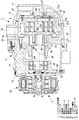
図1は、本発明を適用する空気調和装置の冷媒圧縮機に使用されるスクロール圧縮機1の全体構造を示す縦断面図である。
スクロール圧縮機1には、左右に延設された有底筒形状のハウジング3と、ハウジング内部に設けられたスクロール圧縮機構5と、スクロール圧縮機構5を駆動する駆動機構7とが設けられている。
Embodiments according to the present invention will be described below with reference to the drawings.
[First embodiment]
Hereinafter, a first embodiment of the present invention will be described with reference to FIG.
FIG. 1 is a longitudinal sectional view showing the overall structure of a
The
ハウジング3には、リアハウジング9と、フロントハウジング11と駆動部ハウジング13とが設けられている。フロントハウジング11の後部にリアハウジング9がボルトで固定されて密閉空間を形成している。駆動部ハウジング13は鍔付きの略円筒形状をしており、鍔部14がフロントハウジング11の前壁部12にボルトで固定されている。
リアハウジング9の上部には、冷媒の吸入ポート15が穿設されている。また、リアハウジング9の後端部には、冷媒の吐出ポート17が穿設されている。
ハウジング3内におけるフロントハウジング11の後端に、主軸受(第一軸受)19が固定されている。
The
A
A main bearing (first bearing) 19 is fixed to the rear end of the
スクロール圧縮機構5には、主軸受19に固定された固定スクロール21と、主軸受19と固定スクロール21との間にスラスト軸受を介して公転旋回運動が可能に支持された旋回スクロール23と、旋回スクロール23の外面に設けられ旋回スクロール23の公転旋回運動を許容しながらその自転を阻止する周知のオルダムリンク機構25とが設けられている。
The
固定スクロール21は、固定側端板21aと、固定側端板21aの内面に前方に向けて立設された渦巻き状の固定側渦巻体21bと、固定側端板21aの周縁部に形成された円筒状の周壁部21cとを備えている。固定スクロール端板21a中心近傍には、吐出通路27の吐出口を開閉する吐出弁29および吐出弁29の動きを規制する吐出弁リテーナ31が設けられている。
The fixed
旋回スクロール23は、上述した固定側端板21aに対向状態に配された旋回側端板23aと、旋回側端板23aの内面に後方に向けて立設されて固定側渦巻体21bと噛み合わされた渦巻き状の旋回側渦巻体23bとを備えている。旋回側端板23aには、その前面に円筒形状のボス33が軸線を同じくして立設されている。
固定側渦巻体21bおよび旋回側渦巻体23bの先端面にはチップシールが嵌装されている。
The orbiting
A tip seal is fitted to the distal end surfaces of the fixed-
固定スクロール21と旋回スクロール23とは、互いに所定の距離だけ偏心した状態で、固定側渦巻体21bと旋回側渦巻体23bとの互いの側面が複数個所で線接触するように180度の位相差をもって噛み合わされている。また、この状態で、固定側渦巻体21bの先端面および旋回側渦巻体23bのチップシールがそれぞれ旋回側端板23a及び固定側端板21aの内面に密接されている。これにより、固定側渦巻体21bと旋回側渦巻体23bの中心に対して点対称の位置関係となる複数個所に密閉空間となる圧縮室Pが形成される。
The fixed
固定スクロール21と旋回スクロール23との間に、吸入ポート15に接続される吸入室16が設けられている。そして、リアハウジング9と固定スクロール21の外周とで形成される低圧空間部22が吸入室16と連通されて、低圧雰囲気とされている。
なお、旋回スクロール23は、周知のオルダムリンク機構25によって、主軸受19および主軸受19に固定された固定スクロール21に対して、自転が阻止された状態で公転旋回運動可能に構成されている。
A
The orbiting
旋回スクロール23と主軸受19との間には、ボス33の回りに背圧室35が設けられている。
また、ブッシュ47の外周には、一体に回転するバランスウェイト37が嵌装されている。
A
A
駆動機構7には、旋回スクロール23を駆動する回転軸39と、電磁クラッチ(駆動源)43とが備えられている。
回転軸39は、その軸線がハウジング3の軸線に略沿うように水平方向に延設されている。回転軸39は、後方に行くに従い径が大きくなる多段円筒形状をしており、後端部が主軸受19、中間部分がフロントハウジング11に取り付けられたころがり軸受(第二軸受)41にそれぞれ軸支されている。回転軸39の後端には、軸線から所定量偏心された偏心ピン45が突出状態に設けられている。
偏心ピン45は、ボス33の貫通孔に挿入され、偏心ブッシュ47および旋回軸受49を介してボス33を回転可能に支持している。
The
The
The
ころがり軸受41よりも前方の回転軸39には、駆動部ハウジング13との間に、ハウジング3内部空間をシールするメカニカルシール51が設けられている。
電磁クラッチ43は、駆動部ハウジング13の外周に回転可能に取り付けられ、図示しないエンジンによりベルト駆動されるように構成されている。電磁クラッチ43と回転軸39の前端部とは連結されており、電磁クラッチ43の投入により回転軸39が回転駆動される。
A
The
ころがり軸受41の前方に、ころがり軸受41と隣接して、フロントハウジング11と回転軸39との間に微小隙間部(潤滑油シール部)53が設けられている。微小隙間部53は、油膜シールを形成してころがり軸受41の方へ潤滑油が流入するのを阻害するように構成されている。微小隙間部53の隙間は、使用する際の回転速度、潤滑油の種類および温度等の条件により、いずれの場合でも油膜シールが形成される大きさ、例えば、100μmとする。
A minute gap portion (lubricating oil seal portion) 53 is provided between the
微小隙間部53とメカニカルシール51とで油溜り55が画成されている。
微小隙間部53の前側で、駆動部ハウジング13すぐ後に位置する回転軸39には、油ポンプ57が取り付けられている。油ポンプ57の吸引部とハウジング3内部の下部とを連通する吸引連通孔59が設けられている。油ポンプ57は、回転軸39の回動に伴い作動し、ハウジング3内の下部に貯留した潤滑油を吸引連通孔59経由で吸引し、油溜り55に吐出する。そして、回転軸39の内部に設けられた油孔61を通って主軸受19および旋回軸受49へ供給する。
An
An
以上説明した、本実施形態にかかるスクロール圧縮機1の動作について説明する。
電磁クラッチ43を投入すると、回転軸39が回転する。回転軸39の回転により旋回スクロール23はオルダムリンク機構25によって自転を阻止されつつ公転旋回運動を行う。そして、吸入ポート15より冷媒ガスを吸入室16に導入すると固定側渦巻体21bと旋回側渦巻体23bとで形成される圧縮室Pが順次移動することにより圧縮が行われる。圧縮された高圧の冷媒ガスは、吐出通路27を通って、吐出弁29を開いて吐出ポート17より吐出される。吐出ポート17から吐出された高圧の冷媒ガスは空気調和装置の熱交換器に送られる。
The operation of the
When the
このとき、回転軸39の回転に伴い油ポンプ57が作動して、ハウジング3内の下部に貯留している潤滑油を吸引連通孔59から吸引し、加圧して、微小隙間部53とメカニカルシール51とで画成される油溜り55に供給する。そして、加圧され高圧になった潤滑油は圧力差を利用して、油孔61を通って後方へ運ばれ、主軸受19の軸支部および旋回スクロール23のボス33の軸支部を潤滑する。
油ポンプ57は、回転軸39が回転すれば作動するので、始動時から強制的に潤滑油が供給される。また、油ポンプ57は、回転軸39の回転速度に比例して潤滑油の供給量が変化するので、高速運転時には、潤滑油の供給量が増加する。このため、始動時から高速運転時まで必要な潤滑油量を状況に応じて供給できるので、主軸受19や旋回軸受49において焼付け等の不具合が生じることはない。
At this time, the
Since the
そして、油溜り55の前端部を構成するメカニカルシール51は、下流側へ送られる潤滑油の経路を構成していることになる。したがって、メカニカルシール51には常時潤滑油が直接に供給されていることになるので、メカニカルシール51は十分に潤滑されるとともに冷却される。このため、従来の間接給油のように、不必要な潤滑油量の増加をなくせるので、吸入ポート15から吸入される冷媒により圧縮室Pに運ばれる潤滑油量がこの分だけ少なくなる。これに伴い、吐出ポート17から熱交換器へ吐出される高圧の冷媒ガスに含有される油分が減少するので、熱交換器での熱効率の低下を防止できる。
And the
また、油溜り55の後端部は、微小隙間部53により生じる油膜シールにて封止しているので、回転軸39に対して接触するのは油だけである。このため、従来広く採用されていたOリング等の回転軸39に接触するシールに比べて接触により生じる動力損失が少ないので、この分だけ効率低下を防止できる。さらに、シールのために余分な部品がない分、安価に製造できる。
Further, since the rear end portion of the
以下、本実施形態の作用・効果について説明する。
本実施形態にかかるスクロール圧縮機によれば、回転軸39のフロントハウジング11への軸支が給油を必要としないころがり軸受41としているので、ころがり軸受41とメカニカルシール51との間に、微小隙間部53を設けて潤滑油がころがり軸受41の方へ流れるのを封止した。そして、油ポンプにより微小隙間部53とメカニカルシール51との間に潤滑油を供給することとした。これにより、メカニカルシール51には直接潤滑油が供給されることになるので、メカニカルシール51を十分潤滑することができ、かつ冷却することができる。このため、従来のように間接的な給油のために余分な給油を行う必要がなくなるので、不必要な潤滑油量の増加を防止できる。これにより、冷媒に混合する潤滑油量の不必要な増加がなくなるので、熱効率の低下を防止できる。
Hereinafter, the operation and effect of the present embodiment will be described.
According to the scroll compressor according to the present embodiment, since the shaft support of the
また、本実施形態にかかるスクロール圧縮機によれば、回転軸39とフロントハウジング11との間に設けられた微小隙間部53により油膜シールを形成し潤滑油を封止して供給のための油圧を維持するようにしているので、従来において広く採用されていたOリング等に比べて接触損失による効率低下を防止でき、かつ部品数削減に伴い安価とできる。
Further, according to the scroll compressor according to the present embodiment, an oil film seal is formed by the
さらに、本実施形態にかかるスクロール圧縮機によれば、油供給手段として回転軸により駆動される油ポンプ57を採用しているので、回転軸39が回転し始めると潤滑油の供給が強制的に行われることになる。また、高速運転になり回転軸39の回転が上がると、それに伴い油ポンプ57の潤滑油供給量が増加することになる。
したがって、スクロール圧縮機1は起動時から高速運転時まで潤滑油がスムーズに供給されるので、各部において潤滑油不足による焼付きを防止できる。
Furthermore, according to the scroll compressor according to the present embodiment, the
Therefore, since the
なお、本実施形態では、油ポンプ57の吸引部とハウジング3内部の下部とを連通する吸引連通孔59を設けて、潤滑油の供給源を油ポンプ57に近い位置にあるハウジング3内部の下部としたが、本発明はこれに限定されるものではない。例えば、図2に示すように、ハウジング3の下部にボンベ型の油タンク63を取り付け、油タンク63の前端に設けた供給配管65を吸引連通孔59に接続する。そして、油タンク63の後端に設けた油回収管67をリアハウジング9と固定スクロール21とで形成される低圧空間部に接続する。
このようにすると、油ポンプ57の潤滑油供給源である油タンク63は、ハウジング内に形成される低圧空間部22に下方から接続されているので、運転時に油ポンプ57が油タンク63から供給配管65および吸引連通孔59を経由して潤滑油を吸いだして油タンク63内の油量が低下すると、低圧空間部22に蓄積される潤滑油は油タンク63の方に移動して回収される。
したがって、運転時に低圧空間部22に蓄積される潤滑油量が少なくなるので、固定スクロール21と旋回スクロール23とで形成される圧縮室Pに吸引される冷媒とともに吸込まれる余分な潤滑油量が減少する。このため、冷媒に混合され、融解されて、スクロール圧縮機1より外部に吐出される潤滑油量を少なくすることができるので、冷媒中の潤滑油循環量が多くなって冷凍能力を低下させることを防止できる。
In the present embodiment, a
In this case, the
Accordingly, the amount of lubricating oil accumulated in the
[第二実施形態]
次に、本発明の第二実施形態について、図3を用いて説明する。
本実施形態におけるスクロール圧縮機1は、油供給手段の構成が前述した第1実施形態のものと異なる。その他の構成要素については前述した第一実施形態のものと同じであるので、ここではそれら構成要素についての説明は省略する。
なお、前述した第一実施形態と同一の部材には同一の符号を付している。
[Second Embodiment]
Next, a second embodiment of the present invention will be described with reference to FIG.
The
In addition, the same code | symbol is attached | subjected to the member same as 1st embodiment mentioned above.
フロントハウジング11の前端下部には、凹所69が設けられている。フロントハウジング11において油溜り55と凹所69との間に、供給連通孔71が設けられている。凹所69に開口している供給連通孔71には、図示しない潤滑油供給源から潤滑油を供給する供給配管73が接続されている。供給配管73では絞りを調節して潤滑油を高圧にしてハウジング3内部の被潤滑部との差圧で供給するように構成されている。
A
以上説明した、本実施形態にかかるスクロール圧縮機1の動作について説明する。
電磁クラッチ43を投入すると、回転軸39が回転する。回転軸39の回転により旋回スクロール23はオルダムリンク機構25によって自転を阻止されつつ公転旋回運動を行う。そして、吸入ポート15より冷媒ガスを吸入室16に導入すると固定側渦巻体21bと旋回側渦巻体23bとで形成される圧縮室Pが順次移動することにより圧縮が行われる。圧縮された高圧の冷媒ガスは、吐出通路27を通って、吐出弁29を開いて吐出ポート17より吐出される。吐出ポート17から吐出された高圧の冷媒ガスは空気調和装置の熱交換器に送られる。
The operation of the
When the
スクロール圧縮機1の始動時、潤滑油供給源から高圧にされた潤滑油を供給配管73から供給連通孔71を介して、微小隙間部53とメカニカルシール51とで画成される油溜り55に供給する。そして、供給された高圧の潤滑油は圧力差を利用して、油孔61を通って後方へ運ばれ、主軸受19の軸支部および旋回スクロール23のボス33の軸支部を潤滑する。
このように、スクロール圧縮機1側では、供給連通孔71を設けるだけでよいので、構造が簡素化され、安価に製造できる。
When the
As described above, since only the
そして、油溜り55の前端部を構成するメカニカルシール51は、下流側へ送られる潤滑油の経路を構成していることになる。したがって、メカニカルシール51には常時潤滑油が直接に供給されていることになるので、メカニカルシール51は十分に潤滑されるとともに冷却される。このため、従来の間接給油のように、不必要な潤滑油量の増加をなくせるので、吸入ポート15から吸入される冷媒により圧縮室Pに運ばれる潤滑油量がこの分だけ少なくなる。これに伴い、吐出ポート17から熱交換器へ吐出される高圧の冷媒ガスに含有される油分が減少するので、熱交換器での熱効率の低下を防止できる。
And the
また、油溜り55の後端部は、微小隙間部53により生じる油膜シールにて封止しているので、回転軸39に対して接触するのは油だけである。このため、従来広く採用されていたOリング等の回転軸39に接触するシールに比べて接触により生じる動力損失が少ないので、この分だけ効率低下を防止できる。さらに、シールのために余分な部品がない分、安価に製造できる。
Further, since the rear end portion of the
以下、本実施形態の作用・効果について説明する。
本実施形態にかかるスクロール圧縮機1によれば、回転軸39のフロントハウジング11への軸支が給油を必要としないころがり軸受41としているので、ころがり軸受41とメカニカルシール51との間に、微小隙間部53を設けて潤滑油がころがり軸受41の方へ流れるのを封止した。そして、油ポンプにより微小隙間部53とメカニカルシール51との間に潤滑油を供給することとした。これにより、メカニカルシール51には直接潤滑油が供給されることになるので、メカニカルシール51を十分潤滑することができ、かつ冷却することができる。このため、従来のように間接的な給油のために余分な給油を行う必要がなくなるので、不必要な潤滑油量の増加を防止できる。これにより、冷媒に混合する潤滑油量の不必要な増加がなくなるので、熱効率の低下を防止できる。
Hereinafter, the operation and effect of the present embodiment will be described.
According to the
また、本実施形態にかかるスクロール圧縮機によれば、回転軸39とフロントハウジング11との間に設けられた微小隙間部53により油膜シールを形成し潤滑油を封止して供給のための油圧を維持するようにしているので、従来において広く採用されていたOリング等に比べて接触損失による効率低下を防止でき、かつ部品数削減に伴い安価とできる。
Further, according to the scroll compressor according to the present embodiment, an oil film seal is formed by the
このように、油供給手段は、外部の潤滑油源との間で生じる差圧を利用して供給するように構成されているので、スクロール圧縮機1内の構造が簡素化でき、安価に製造できる。
In this way, the oil supply means is configured to supply by utilizing the differential pressure generated between the external lubricating oil source, so the structure in the
なお、本実施形態では、潤滑油の供給源と被潤滑部との間の差圧のみを利用して潤滑油を供給しているが、本発明はこれに限定されるものではない。例えば、図4に示すように、回転軸39に油ポンプ75を追加して設けてもよい。そして、油ポンプ75の吸引部はハウジング3内部の下部に連通し、同部に貯留する潤滑油が吸引されるよう構成されている。なお、油ポンプ75の吸引部に接続される潤滑油源としては、図2に示す油タンク63でもよいし、低圧であるまったく別の容器でもよい。
このようにすると、差圧による給油と油ポンプによる給油とが併せて行われることになるので、それぞれの給油量を低減することができる。このため、差圧給油機構および油ポンプ75それぞれの構造を簡素化できる。また、相互に機能を補完できる。
例えば、低負荷運転時などの差圧が小さい時でも油ポンプ75が作動して必要な潤滑油量を確保できる。
また、油ポンプ75による潤滑油の供給量に見合う分だけ、差圧による潤滑油の供給量を低減できる。このため、例えば、差圧による給油を固定絞りとし、低差圧時に必要な給油量となるよう設定した場合でも、高差圧時に給油量過多となる影響を低減できる。したがって、構造が簡単で、操作が不要となる固定絞りとしても、給油量の増加により冷媒へ混入する潤滑油量が増加して熱効率が低下するのを防止できる。
In this embodiment, the lubricating oil is supplied using only the differential pressure between the lubricating oil supply source and the portion to be lubricated, but the present invention is not limited to this. For example, as shown in FIG. 4, an
If it does in this way, since oil supply by differential pressure and oil supply by an oil pump will be performed collectively, each oil supply amount can be reduced. For this reason, the structures of the differential pressure oil supply mechanism and the
For example, even when the differential pressure is small, such as during low-load operation, the
Further, the amount of lubricating oil supplied by the differential pressure can be reduced by an amount corresponding to the amount of lubricating oil supplied by the
1 スクロール圧縮機
3 ハウジング
19 主軸受
21 固定スクロール
22 低圧空間部
23 旋回スクロール
39 回転軸
41 ころがり軸受
51 メカニカルシール
57 油ポンプ
63 油タンク
DESCRIPTION OF
Claims (5)
該第一軸受と前記ハウジングに設けられた第二軸受とによってそれぞれ回転自在に軸支されるとともに、前記ハウジングの外部で駆動源に接続される回転軸と、
前記第一軸受および第二軸受よりも前記駆動源側の回転軸に設けられたメカニカルシールと、
前記駆動源に対して反対側位置で、前記ハウジング内に固定支持された固定スクロールと、
前記第一軸受に支持され、前記固定スクロールとかみ合わされた状態で旋回駆動される旋回スクロールと、を具備するスクロール圧縮機において、
前記第二軸受は、ころがり軸受とされ、
該ころがり軸受の前記駆動源側に、前記ころがり軸受側への潤滑油の流入を封止する潤滑油シール部を設け、
該潤滑油シール部と前記メカニカルシールとの間に潤滑油を供給し、前記旋回スクロールの駆動部および前記第一軸受へ前記回転軸の内部を通って潤滑油を供給する油供給手段を設けたことを特徴とするスクロール圧縮機。 A first bearing provided in a sealed housing;
A rotary shaft rotatably supported by the first bearing and a second bearing provided in the housing, and connected to a drive source outside the housing;
A mechanical seal provided on the rotary shaft closer to the drive source than the first bearing and the second bearing;
A fixed scroll fixedly supported in the housing at a position opposite to the drive source;
A scroll compressor supported by the first bearing and orbiting scroll driven in a state of being engaged with the fixed scroll;
The second bearing is a rolling bearing,
To the driving power source side of the rolling bearing, it is provided a lubricating oil seal unit for sealing the flow of lubricating oil to the rolling bearing side,
Oil supply means is provided for supplying lubricating oil between the lubricating oil seal portion and the mechanical seal, and supplying the lubricating oil to the drive portion of the orbiting scroll and the first bearing through the inside of the rotary shaft . A scroll compressor characterized by that.
前記油ポンプは、前記油タンクから潤滑油を供給することを特徴とする請求項3に記載されたスクロール圧縮機。 An oil tank connected from below to a low pressure space formed in the housing is provided,
The scroll compressor according to claim 3, wherein the oil pump supplies lubricating oil from the oil tank.
Priority Applications (1)
| Application Number | Priority Date | Filing Date | Title |
|---|---|---|---|
| JP2004096979A JP4301985B2 (en) | 2004-03-29 | 2004-03-29 | Scroll compressor |
Applications Claiming Priority (1)
| Application Number | Priority Date | Filing Date | Title |
|---|---|---|---|
| JP2004096979A JP4301985B2 (en) | 2004-03-29 | 2004-03-29 | Scroll compressor |
Publications (2)
| Publication Number | Publication Date |
|---|---|
| JP2005282446A JP2005282446A (en) | 2005-10-13 |
| JP4301985B2 true JP4301985B2 (en) | 2009-07-22 |
Family
ID=35181123
Family Applications (1)
| Application Number | Title | Priority Date | Filing Date |
|---|---|---|---|
| JP2004096979A Expired - Lifetime JP4301985B2 (en) | 2004-03-29 | 2004-03-29 | Scroll compressor |
Country Status (1)
| Country | Link |
|---|---|
| JP (1) | JP4301985B2 (en) |
Families Citing this family (2)
| Publication number | Priority date | Publication date | Assignee | Title |
|---|---|---|---|---|
| JP6462265B2 (en) | 2014-08-08 | 2019-01-30 | 三菱重工業株式会社 | Open type compressor |
| JP7052563B2 (en) * | 2018-05-28 | 2022-04-12 | 株式会社デンソー | Compressor |
-
2004
- 2004-03-29 JP JP2004096979A patent/JP4301985B2/en not_active Expired - Lifetime
Also Published As
| Publication number | Publication date |
|---|---|
| JP2005282446A (en) | 2005-10-13 |
Similar Documents
| Publication | Publication Date | Title |
|---|---|---|
| EP2131040B1 (en) | Motor-driven scroll type compressor | |
| JP2513444B2 (en) | High pressure rotary compressor | |
| JP5178668B2 (en) | Scroll compressor | |
| US5277564A (en) | Closed type scroll compressor with spherical slide bearing for the oil tube | |
| KR20000048095A (en) | Scroll compressor | |
| JPH11141483A (en) | Electric gas compressor | |
| EP1464840A1 (en) | Scroll compressor | |
| US8128388B2 (en) | Scroll-type expansion machine | |
| JP2007085297A (en) | Scroll compressor | |
| JP4301985B2 (en) | Scroll compressor | |
| JP4258132B2 (en) | Rotary multistage compressor | |
| JP3045961B2 (en) | Scroll gas compression | |
| CN213981182U (en) | Movable scroll assembly and scroll compressor comprising same | |
| JP2006307753A (en) | Scroll expander | |
| JP2007162679A (en) | Fluid machine | |
| JP2006083867A (en) | Scroll compressor | |
| JP2006037896A (en) | Scroll compressor | |
| JP5285339B2 (en) | Scroll compressor | |
| JP2006214335A (en) | Scroll compressor | |
| JP3988524B2 (en) | Hermetic compressor | |
| JP3585661B2 (en) | Rotary compressor and refrigeration apparatus equipped with the compressor | |
| WO2020261558A1 (en) | Scroll compressor and refrigeration cycle device | |
| JP2001304152A (en) | Scroll compressor | |
| JP4486224B2 (en) | Scroll compressor | |
| JP2017172484A (en) | Scroll compressor |
Legal Events
| Date | Code | Title | Description |
|---|---|---|---|
| A621 | Written request for application examination |
Free format text: JAPANESE INTERMEDIATE CODE: A621 Effective date: 20061214 |
|
| A131 | Notification of reasons for refusal |
Free format text: JAPANESE INTERMEDIATE CODE: A131 Effective date: 20081118 |
|
| A977 | Report on retrieval |
Free format text: JAPANESE INTERMEDIATE CODE: A971007 Effective date: 20081120 |
|
| A521 | Written amendment |
Free format text: JAPANESE INTERMEDIATE CODE: A523 Effective date: 20090119 |
|
| TRDD | Decision of grant or rejection written | ||
| A01 | Written decision to grant a patent or to grant a registration (utility model) |
Free format text: JAPANESE INTERMEDIATE CODE: A01 Effective date: 20090407 |
|
| A01 | Written decision to grant a patent or to grant a registration (utility model) |
Free format text: JAPANESE INTERMEDIATE CODE: A01 |
|
| A61 | First payment of annual fees (during grant procedure) |
Free format text: JAPANESE INTERMEDIATE CODE: A61 Effective date: 20090421 |
|
| FPAY | Renewal fee payment (event date is renewal date of database) |
Free format text: PAYMENT UNTIL: 20120501 Year of fee payment: 3 |
|
| R151 | Written notification of patent or utility model registration |
Ref document number: 4301985 Country of ref document: JP Free format text: JAPANESE INTERMEDIATE CODE: R151 |
|
| FPAY | Renewal fee payment (event date is renewal date of database) |
Free format text: PAYMENT UNTIL: 20120501 Year of fee payment: 3 |
|
| FPAY | Renewal fee payment (event date is renewal date of database) |
Free format text: PAYMENT UNTIL: 20130501 Year of fee payment: 4 |
|
| FPAY | Renewal fee payment (event date is renewal date of database) |
Free format text: PAYMENT UNTIL: 20140501 Year of fee payment: 5 |
|
| R250 | Receipt of annual fees |
Free format text: JAPANESE INTERMEDIATE CODE: R250 |
|
| S111 | Request for change of ownership or part of ownership |
Free format text: JAPANESE INTERMEDIATE CODE: R313111 |
|
| R350 | Written notification of registration of transfer |
Free format text: JAPANESE INTERMEDIATE CODE: R350 |