EP3150853B2 - Dosierpumpe, insbesondere brennstoffdosierpumpe für ein fahrzeugheizgerät - Google Patents
Dosierpumpe, insbesondere brennstoffdosierpumpe für ein fahrzeugheizgerät Download PDFInfo
- Publication number
- EP3150853B2 EP3150853B2 EP16190711.8A EP16190711A EP3150853B2 EP 3150853 B2 EP3150853 B2 EP 3150853B2 EP 16190711 A EP16190711 A EP 16190711A EP 3150853 B2 EP3150853 B2 EP 3150853B2
- Authority
- EP
- European Patent Office
- Prior art keywords
- pump
- pump piston
- piston
- housing
- fluid
- Prior art date
- Legal status (The legal status is an assumption and is not a legal conclusion. Google has not performed a legal analysis and makes no representation as to the accuracy of the status listed.)
- Active
Links
- 239000000446 fuel Substances 0.000 title claims description 13
- 239000012530 fluid Substances 0.000 claims description 44
- 239000012781 shape memory material Substances 0.000 claims description 16
- 230000009471 action Effects 0.000 claims description 10
- 230000005540 biological transmission Effects 0.000 claims description 7
- 229910045601 alloy Inorganic materials 0.000 claims description 3
- 239000000956 alloy Substances 0.000 claims description 3
- 230000008878 coupling Effects 0.000 claims description 2
- 238000010168 coupling process Methods 0.000 claims description 2
- 238000005859 coupling reaction Methods 0.000 claims description 2
- 229910001285 shape-memory alloy Inorganic materials 0.000 claims 1
- 230000008859 change Effects 0.000 description 9
- 230000003993 interaction Effects 0.000 description 7
- 238000002485 combustion reaction Methods 0.000 description 5
- 230000000694 effects Effects 0.000 description 5
- 230000005284 excitation Effects 0.000 description 3
- 239000007788 liquid Substances 0.000 description 3
- 230000000149 penetrating effect Effects 0.000 description 3
- 239000002828 fuel tank Substances 0.000 description 2
- 238000004519 manufacturing process Methods 0.000 description 2
- 230000000737 periodic effect Effects 0.000 description 2
- 210000000746 body region Anatomy 0.000 description 1
- 238000010276 construction Methods 0.000 description 1
- 230000007423 decrease Effects 0.000 description 1
- 238000006073 displacement reaction Methods 0.000 description 1
- 230000006870 function Effects 0.000 description 1
- 230000005283 ground state Effects 0.000 description 1
- 229910001004 magnetic alloy Inorganic materials 0.000 description 1
- 239000000696 magnetic material Substances 0.000 description 1
- 239000007769 metal material Substances 0.000 description 1
- 238000005086 pumping Methods 0.000 description 1
- 230000004044 response Effects 0.000 description 1
- 230000007704 transition Effects 0.000 description 1
Images

Classifications
-
- F—MECHANICAL ENGINEERING; LIGHTING; HEATING; WEAPONS; BLASTING
- F04—POSITIVE - DISPLACEMENT MACHINES FOR LIQUIDS; PUMPS FOR LIQUIDS OR ELASTIC FLUIDS
- F04B—POSITIVE-DISPLACEMENT MACHINES FOR LIQUIDS; PUMPS
- F04B17/00—Pumps characterised by combination with, or adaptation to, specific driving engines or motors
- F04B17/03—Pumps characterised by combination with, or adaptation to, specific driving engines or motors driven by electric motors
- F04B17/04—Pumps characterised by combination with, or adaptation to, specific driving engines or motors driven by electric motors using solenoids
- F04B17/042—Pumps characterised by combination with, or adaptation to, specific driving engines or motors driven by electric motors using solenoids the solenoid motor being separated from the fluid flow
-
- F—MECHANICAL ENGINEERING; LIGHTING; HEATING; WEAPONS; BLASTING
- F04—POSITIVE - DISPLACEMENT MACHINES FOR LIQUIDS; PUMPS FOR LIQUIDS OR ELASTIC FLUIDS
- F04B—POSITIVE-DISPLACEMENT MACHINES FOR LIQUIDS; PUMPS
- F04B13/00—Pumps specially modified to deliver fixed or variable measured quantities
-
- F—MECHANICAL ENGINEERING; LIGHTING; HEATING; WEAPONS; BLASTING
- F04—POSITIVE - DISPLACEMENT MACHINES FOR LIQUIDS; PUMPS FOR LIQUIDS OR ELASTIC FLUIDS
- F04B—POSITIVE-DISPLACEMENT MACHINES FOR LIQUIDS; PUMPS
- F04B17/00—Pumps characterised by combination with, or adaptation to, specific driving engines or motors
- F04B17/03—Pumps characterised by combination with, or adaptation to, specific driving engines or motors driven by electric motors
- F04B17/04—Pumps characterised by combination with, or adaptation to, specific driving engines or motors driven by electric motors using solenoids
-
- F—MECHANICAL ENGINEERING; LIGHTING; HEATING; WEAPONS; BLASTING
- F04—POSITIVE - DISPLACEMENT MACHINES FOR LIQUIDS; PUMPS FOR LIQUIDS OR ELASTIC FLUIDS
- F04B—POSITIVE-DISPLACEMENT MACHINES FOR LIQUIDS; PUMPS
- F04B53/00—Component parts, details or accessories not provided for in, or of interest apart from, groups F04B1/00 - F04B23/00 or F04B39/00 - F04B47/00
- F04B53/10—Valves; Arrangement of valves
- F04B53/12—Valves; Arrangement of valves arranged in or on pistons
- F04B53/125—Reciprocating valves
- F04B53/126—Ball valves
-
- H—ELECTRICITY
- H10—SEMICONDUCTOR DEVICES; ELECTRIC SOLID-STATE DEVICES NOT OTHERWISE PROVIDED FOR
- H10N—ELECTRIC SOLID-STATE DEVICES NOT OTHERWISE PROVIDED FOR
- H10N35/00—Magnetostrictive devices
-
- H—ELECTRICITY
- H10—SEMICONDUCTOR DEVICES; ELECTRIC SOLID-STATE DEVICES NOT OTHERWISE PROVIDED FOR
- H10N—ELECTRIC SOLID-STATE DEVICES NOT OTHERWISE PROVIDED FOR
- H10N35/00—Magnetostrictive devices
- H10N35/80—Constructional details
- H10N35/85—Magnetostrictive active materials
-
- F—MECHANICAL ENGINEERING; LIGHTING; HEATING; WEAPONS; BLASTING
- F23—COMBUSTION APPARATUS; COMBUSTION PROCESSES
- F23K—FEEDING FUEL TO COMBUSTION APPARATUS
- F23K2300/00—Pretreatment and supply of liquid fuel
- F23K2300/20—Supply line arrangements
- F23K2300/201—Pumps
Definitions
- the present invention relates to a metering pump, in particular a fuel metering pump for a vehicle heater, comprising a pump piston that can be moved back and forth in a pump chamber for ejecting and receiving fluid and a drive arrangement for the pump piston, according to the preamble of claim 1.
- a metering pump is known from WO-A-99/45631 famous.
- a metering pump for delivering fuel to the combustion chamber of a fuel-powered vehicle heater is known.
- a pump piston which can be moved back and forth in its longitudinal direction in order to receive fuel to be delivered in a pump chamber and to eject fuel received in the pump chamber from the pump chamber, is fixedly connected to an armature.
- the armature or the pump piston is surrounded by a coil which generates a magnetic field when excited. Through interaction with the magnetic field, a force is exerted on the armature, which acts on it and thus on the pump piston in the direction of ejecting fuel from the pump chamber.
- the pump piston When the excitation of the coil is terminated and thus the generation of the magnetic field is terminated, the pump piston is moved together with the armature by a return spring acting as a return element in the direction out of the pump chamber. During its reciprocating movement, the pump piston moves between two stops, which are associated with respective elastic elements, in order to dampen the stop of the pump piston in both end positions of the reciprocating movement.
- a pump is known through which liquid fuel can be conveyed to a combustion chamber of a vehicle heater.
- This pump includes a tubular pump body made of magnetic shape memory material. When a magnetic field is generated, the pump body made of magnetic shape memory material is deformed by interaction with it. The volume enclosed by the tubular pump body is changed by the deformation. This change in volume, which occurs alternately when the excitation is excited or when it is ended, can be used to convey the liquid fuel in the direction of a combustion chamber.
- the DE 10 2010 010 801 B4 discloses an actuator having a drive element made of magnetic shape memory material.
- a magnetic field can be generated by a coil device surrounding the drive element.
- the driving element made of magnetic shape memory material changes its length and thereby displaces a plunger.
- a metering pump in particular a fuel metering pump for a vehicle heater, comprising a pump piston that can be moved back and forth in a pump chamber for ejecting and receiving fluid and a drive arrangement for the pump piston.
- the drive arrangement comprises at least one drive element constructed with magnetic shape memory material.
- the present invention uses the effect that a body made of magnetic shape memory material, namely a drive element, changes its shape as a result of the interaction with a magnetic field.
- this change in shape can be used to generate a force that moves a pump piston.
- the pumping effect is achieved by the back and forth movement of a pump piston in a pump chamber and the drive element made of magnetic shape memory material is only used to generate a driving force for the pump piston, must be based on a complex shape, for example a hollow body design, in which at least one Drive element are not respected.
- the occurrence of impact noises at the respective dead centers of movement can be avoided since on the one hand the movement of the pump piston can be slowed down when approaching a respective dead center of movement by correspondingly varying the magnetic field acting on the at least one drive element.
- a direct impact contact of the pump piston with its movement-limiting components can be practically completely avoided during a respective reversal of movement.
- the shape memory magnetic material may comprise a shape memory magnetic alloy. In terms of the achievable change in shape or volume, this has proven to be particularly advantageous Proven use of a NiMnGa alloy.
- the drive arrangement comprises a magnetic field generating unit, preferably with an electrically excitable coil arrangement, for generating a magnetic field acting on the at least one drive element.
- the at least one drive element acts on the pump piston in a first direction of application, with the at least one drive element preferably acting on the pump piston in the direction of ejecting fluid from the pump chamber when acted upon in the first direction of application.
- the drive arrangement comprises a restoring element for acting on the pump piston in a second acting direction that is essentially opposite to the first acting direction, with the restoring element preferably acting on the pump piston in the direction of receiving fluid in the pump chamber when acted upon in the second acting direction.
- the restoring element is the at least one drive element for restoring the at least one drive element into a basic state to be assumed when the magnetic field is not generated, i.e. a magnetic field-free state assigned.
- both the pump piston and the drive element are reset by one and the same component or one and the same assembly.
- this restoring effect can be achieved in that the restoring element comprises a restoring spring.
- the at least one drive element is arranged in a drive element housing providing a fluid inlet channel.
- the pump piston can be moved back and forth in a pump piston housing in the direction of a pump longitudinal axis.
- the drive element housing and the pump piston housing provide a through opening for a transmission element that couples the at least one drive element to the pump piston for drive force transmission and for the passage of fluid.
- a pump chamber housing providing the pump chamber be provided on the pump piston housing.
- the pump chamber housing can also be used to support a restoring element that acts on the pump piston.
- a fluid passage channel penetrating the pump piston can be provided in order to introduce fluid to be pumped into the pump chamber.
- a defined direction of flow for the fluid to be delivered by the back and forth movement of the pump piston can be achieved by providing an inlet check valve in the pump piston and/or by providing an outlet check valve in a pump chamber housing.
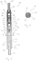
- the Figures 1 and 2 show a metering pump, generally designated 10, which can be used, for example, to convey liquid fuel from a fuel tank in the direction of a combustion chamber of a fuel-operated motor vehicle heater.
- the metering pump 10 includes a pump housing, generally designated 12 and composed of several parts.
- An inlet end area 14 of the pump housing 12 is provided with an inlet connector 16 to which, for example, a hose line leading to a fuel tank can be connected.
- An outlet connector 20 is provided on an outlet end region 18, to which a hose line leading, for example, to a combustion chamber can be connected.
- the pump housing 12 comprises a drive element housing 22 which is elongated in the direction of a pump longitudinal axis L and which provides the inlet end area 14 and also the inlet connector 16 .
- a fluid inlet channel 24 penetrating the drive element housing 22 completely in the direction of the longitudinal axis L of the pump is provided.
- this fluid inlet channel has a step-like extension 26, on which a drive element 28 made of magnetic shape memory material, e.g. B. a NiMnGa alloy supported.
- the drive element 28 forms an essential part of a drive arrangement generally designated 30 .
- the drive element 28 is constructed essentially like a plate, so that on both sides of the same a flow volume of the fluid inlet channel 24 is provided and the fluid to be delivered, for example fuel, can flow through the drive element housing 22 while flowing around the drive element 28.
- the drive element housing 22 is firmly and fluid-tightly connected to a pump piston housing 34, which is likewise elongated in the direction of the pump longitudinal axis L.
- a pump piston, generally designated 36 is accommodated in the pump piston housing 34 in such a way that it can be moved in the direction of the longitudinal axis L of the pump.
- a contact attachment 40 for the pump piston 36 is provided on the end area 38 of the pump piston housing 34 which is close to the end area 32 of the drive element housing 22 or is connected thereto.
- a through opening 42 is provided in contact shoulder 40 or in end region 38 of pump piston housing 34, which, together with axially open end region 32 of drive element housing 22, allows fluid to flow from fluid inlet channel 24 into pump piston housing 34 on the one hand, and allows a drive element 28 to pass through on the other with the pump piston 36 for driving force transmission coupling transmission member 44 allows.
- the pump piston 36 is constructed with two piston parts 46, 48 which are inserted into one another and are firmly connected to one another.
- the piston part 46 has in its area facing the contact shoulder 40 a plate-like end section 50 which, when the pump piston 36 rests on the contact shoulder 40, closes the passage opening 42 against the passage of fluid.
- a valve seat 60 for example conical, for an inlet non-return valve, generally designated 62, is provided in a central body region 58 of the piston part 46 connected to the plate-like end region 50, for example via three webs 52, 54, 56.
- a valve seat 60 for example conical, for an inlet non-return valve, generally designated 62, is provided in a central body region 58 of the piston part 46 connected to the plate-like end region 50, for example via three webs 52, 54, 56.
- a valve seat 60 for example conical, for an inlet non-return valve, generally designated 62, is provided in 62.
- the piston part 48 of the pump piston 36 engages in a pump chamber 72 formed in a pump chamber housing 70 .
- the volume of the pump chamber 72 that can be filled with fluid is reduced. Due to the increasing fluid pressure in the pump chamber 72 and in a fluid passage duct 74 penetrating the pump piston 36 essentially in the direction of the pump longitudinal axis L, the inlet check valve 62 is subjected to an even greater load in the direction of its closed position, so that the fluid contained in the pump chamber 72 can only flow via a Outlet check valve 76 can escape from the pump chamber 72 and flow out via the outlet port 20 .
- the outlet non-return valve 76 comprises a valve seat 78 formed in the pump chamber housing 70 and a valve element 82, which is pressed against this valve seat 78 by a valve spring 80 and is embodied, for example, as a ball nozzle part 84 used in a fluid-tight manner.
- the pump piston 36 in the representation of 1 down Moves the pump piston 36 in the representation of 1 down, the volume of the pump chamber 72 that can be filled with fluid increases.
- the valve element 64 of the inlet check valve 62 can lift off its valve seat 60, so that fluid can flow out of the fluid inlet channel 24 or out of the interior volume area of the pump piston housing 34 into the fluid passage channel 74 of the pump piston 36 and thus can also reach the area of the pump chamber 72 .
- the outlet non-return valve 76 prevents fluid that has already been discharged from the pump chamber 72 from flowing back via the outlet connector 20 .
- the previously mentioned drive arrangement 30 is provided with its drive element 28 made of magnetic shape memory material.
- the drive assembly 30 further includes an in 4 magnetic field generation arrangement 86 shown in principle. This can, for example, comprise a coil arrangement 90 guided around a yoke 88 made of metal material. When the coil arrangement 90 is excited, a magnetic field M is generated between the two opposite poles 92, 94 of the yoke 88. This magnetic field M extends essentially orthogonally to the pump longitudinal axis L and also orthogonally to the plate-like drive element 28.
- the drive element 28 made of magnetic shape memory material changes its shape, so that this, like this, represents the transition from the state without a magnetic field 1 to that representing the state with a magnetic field figure 3 shows, its shape, especially its length, changes. As the length increases, the width of the drive element 28 decreases. In this way, a change in length of the drive element 28 of up to approximately 10% can be achieved.
- This change in length of the drive element 28 when the magnetic field M is generated by the magnetic field generating arrangement 86 is used to bring about a corresponding displacement of the pump piston 36 .
- a driving force is transmitted to the piston part 46 of the pump piston 36 by the, for example, pin-like or bolt-like transmission element 44 .
- the pump piston is displaced against the restoring effect of a restoring spring 94 on piston part 46 on the one hand and on pump chamber housing 70 on the other hand and surrounding piston part 48 Pump chamber 72 and is thus applied in the direction of receiving fluid to be pumped in the pump chamber 72.
- the restoring spring 94 forms a second restoring element 98 through which a restoring force is exerted on the drive element 28 via the pump piston 36 or the piston part 46 and the transmission element 44 .
- This is necessary because although the drive element 28 made of magnetic shape-memory material changes its shape or length when it is exposed to the magnetic field M, it does not automatically return to its previously assumed and, for example, in 1 shown ground state can return. This requires the action of an external force, which is generated in the exemplary embodiment shown by the restoring spring 94 in its function as the second restoring element 98 .
- a corresponding alternating back and forth movement of the pump piston can be brought about, on the one hand under the action of the magnetic field M generated by means of the magnetic field generating arrangement 86 and on the other hand by the action of the return spring 94 .
- the work cycles performed per unit of time ie, for example, per second, and thus also the ejected volume of the fluid to be conveyed can be set.
- the volume of the pump chamber 72 can be used to the maximum extent if the pump piston 36 is moved back and forth between its two maximum end positions that can be assumed during this back and forth movement. On the one hand, this is an end position in which the piston part 46 rests on the contact shoulder 40, and on the other hand it is an end position in which the return spring 94 is compressed to the maximum extent or, if necessary, the piston part 48 abuts against a bottom region of the pump chamber 72.
- the extent of the change in shape or length of the drive element 28 can also be set in a simple manner by appropriately adjusting the field strength of the magnetic field M, so that the pump piston 36 does not necessarily have to move between these two maximum end positions - Is moved back and forth, but only performs a shorter movement with each stroke and correspondingly only a smaller volume of fluid is ejected from the pump chamber 72.
- the frequency of the reciprocating movement is an influence on the amount of fluid to be pumped, but it can also be influenced in particular by the extent of the stroke, i.e. the amplitude of the reciprocating movement, the pumped volume to be influenced.
- a drive element 28 made of magnetic shape memory material allows an operating frequency in the kHz range. If the amplitude is set correspondingly low, a very small volume of the fluid to be pumped can also be ejected with each work cycle.
- the defined generation of the magnetic field M also enables a gradual deceleration of the pump piston 36 when approaching a respective end position, so that a striking of the pump piston 36 leading to perceptible vibrations or noises can be avoided.
Landscapes
- Engineering & Computer Science (AREA)
- Mechanical Engineering (AREA)
- General Engineering & Computer Science (AREA)
- Physics & Mathematics (AREA)
- Fluid Mechanics (AREA)
- Electromagnetic Pumps, Or The Like (AREA)
- Reciprocating Pumps (AREA)
Description
- Die vorliegende Erfindung betrifft eine Dosierpumpe, insbesondere Brennstoffdosierpumpe für ein Fahrzeugheizgerät, umfassend einen in einer Pumpenkammer zum Ausstoßen und Aufnehmen von Fluid hin- und herbewegbaren Pumpenkolben und eine Antriebsanordnung für den Pumpenkolben, gemäß dem Oberbegriff des Anspruchs 1. Eine derartige Dosierpumpe ist aus der
WO-A-99/45631 - Aus der
DE 10 2011 004 362 A1 ist eine Dosierpumpe zum Fördern von Brennstoff zur Brennkammer eines brennstoffbetriebenen Fahrzeugheizgeräts bekannt. Ein zum Aufnehmen von zu förderndem Brennstoff in einer Pumpenkammer und zum Ausstoßen von in der Pumpenkammer aufgenommenem Brennstoff aus der Pumpenkammer in seiner Längsrichtung hin- und herbewegbarer Pumpenkolben ist mit einem Anker fest verbunden. Der Anker bzw. der Pumpenkolben ist umgeben von einer Spule, welche bei Erregung ein Magnetfeld erzeugt. Durch Wechselwirkung mit dem Magnetfeld wird auf den Anker eine Kraft ausgeübt, welche diesen und damit den Pumpenkolben in Richtung Ausstoßen von Brennstoff aus der Pumpenkammer beaufschlagt. Bei Beendigung der Erregung der Spule und somit Beendigung der Erzeugung des Magnetfelds wird der Pumpenkolben zusammen mit dem Anker durch eine als Rückstellelement wirksame Rückstellfeder in Richtung aus der Pumpenkammer heraus bewegt. Bei seiner Hin- und Herbewegung bewegt sich der Pumpenkolben zwischen zwei Anschlägen, welchen jeweilige elastische Elemente zugeordnet sind, um in beiden Endpositionen der Hin- und Herbewegung den Anschlag des Pumpenkolbens zu dämpfen. - Aus der
DE 10 2013 221 744 A1 ist eine Pumpe bekannt, durch welche flüssiger Brennstoff zu einer Brennkammer eines Fahrzeugheizgeräts gefördert werden kann. Diese Pumpe umfasst einen röhrenartigen Pumpenkörper aus magnetischem Formgedächtnismaterial. Bei Erzeugung eines Magnetfeldes wird durch Wechselwirkung mit diesem der Pumpenkörper aus magnetischem Formgedächtnismaterial verformt. Durch die Verformung wird das von dem rohrartigen Pumpenkörper umschlossene Volumen verändert. Diese bei Erregung bzw. Beenden der Erregung alternierend auftretende Volumenänderung kann dazu genutzt werden, den flüssigen Brennstoff in Richtung zu einer Brennkammer zu fördern. - Die
DE 10 2010 010 801 B4 offenbart einen Aktuator mit einem Antriebselement aus magnetischem Formgedächtnismaterial. Durch eine das Antriebselement umgebende Spulenvorrichtung kann ein Magnetfeld erzeugt werden. In Reaktion auf die Erzeugung des Magnetfeldes ändert das Antriebselement aus magnetischem Formgedächtnismaterial seine Länge und verschiebt dadurch einen Stößel. - Es ist die Aufgabe der vorliegenden Erfindung, eine kostengünstig aufzubauende Dosierpumpe bereitzustellen, mit welcher eine verbesserte Dosierbarkeit des geförderten Mediums erreicht wird und die Entstehung von Anschlaggeräuschen bei der Bewegung eines Pumpenkolbens vermieden wird.
- Erfindungsgemäß wird diese Aufgabe gelöst durch eine Dosierpumpe, insbesondere Brennstoffdosierpumpe für ein Fahrzeugheizgerät, umfassend einen in einer Pumpenkammer zum Ausstoßen und Aufnehmen von Fluid hin- und herbewegbaren Pumpenkolben und eine Antriebsanordnung für den Pumpenkolben.
- Dabei ist weiter vorgesehen, dass die Antriebsanordnung wenigstens ein mit magnetischem Formgedächtnismaterial aufgebautes Antriebselement umfasst.
- Die vorliegende Erfindung nutzt einerseits den Effekt, dass durch die Wechselwirkung mit einem Magnetfeld ein aus magnetischem Formgedächtnismaterial aufgebauter Körper, nämlich ein Antriebselement, seine Form ändert. Diese Formänderung kann bei dem erfindungsgemäßen Aufbau dazu genutzt werden, eine einen Pumpenkolben bewegende Kraft zu erzeugen. Da, anders als bei dem aus der
DE 10 2013 221 744 A1 bekannten Aufbau, die Pumpwirkung durch die Hin- und Herbewegung eines Pumpenkolbens in einer Pumpenkammer erreicht wird und das Antriebselement aus magnetischem Formgedächtnismaterial lediglich zur Erzeugung einer Antriebskraft für den Pumpenkolben genutzt wird, muss auf eine komplexe Formgebung, beispielsweise Ausgestaltung als Hohlkörper, bei dem wenigstens einen Antriebselement nicht geachtet werden. Dieses kann mit vergleichsweise einfacher Gestalt bereitgestellt werden, was einerseits dessen Herstellungsvorgang vereinfacht, andererseits deutlich verminderte Herstellungskosten mit sich bringt. Da durch die Wechselwirkung mit einem Magnetfeld die Formänderung des aus magnetischem Formgedächtnismaterial aufgebauten Antriebselements sehr präzise einstellbar ist, nämlich durch Vorgabe der Magnetfeldstärke, kann entsprechend präzise auch das Ausmaß des durch das wenigstens eine Antriebselement bewegten Pumpenkolbens eingestellt werden. Somit besteht nicht nur die Möglichkeit, durch die Frequenz der Hin- und Herbewegung das Volumen des geförderten Mediums zu beeinflussen, sondern auch durch das Ausmaß, also die Amplitude der Hin- und Herbewegung. Insbesondere kann damit das Auftreten von Anschlaggeräuschen an den jeweiligen Bewegungstotpunkten vermieden werden, da einerseits durch entsprechende Variation des auf das wenigstens eine Antriebselement einwirkenden Magnetfeldes die Bewegung des Pumpenkolbens bei Annäherung an einen jeweiligen Bewegungstotpunkt verlangsamt werden kann. Andererseits kann ein unmittelbarer Anschlagkontakt des Pumpenkolbens mit dessen Bewegung begrenzenden Bauteilen bei einer jeweiligen Bewegungsumkehr praktisch vollständig vermieden werden. - Das magnetische Formgedächtnismaterial kann eine magnetische Formgedächtnislegierung umfassen. Als hinsichtlich der erreichbaren Form- bzw. Volumenänderung besonders vorteilhaft hat sich hier der Einsatz einer NiMnGa-Legierung erwiesen.
- Um eine Formänderung des wenigstens einen Antriebselements und somit eine Bewegung des Pumpenkolbens erzielen zu können, wird vorgeschlagen, dass die Antriebsanordnung eine Magnetfelderzeugungseinheit, vorzugsweise mit einer elektrisch erregbaren Spulenanordnung, zur Erzeugung eines auf das wenigstens eine Antriebselement einwirkenden Magnetfeldes umfasst.
- Das wenigstens eine Antriebselement beaufschlagt bei erzeugtem Magnetfeld den Pumpenkolben in einer ersten Beaufschlagungsrichtung, wobei vorzugsweise bei Beaufschlagung in der ersten Beaufschlagungsrichtung das wenigstens eine Antriebselement den Pumpenkolben in Richtung Ausstoßen von Fluid aus der Pumpenkammer beaufschlagt.
- Durch die Wechselwirkung eines Antriebselements mit einem Magnetfeld kann eine Formänderung und damit eine Antriebskraft in einer Richtung erzeugt werden. Um den Pumpenkolben wieder zurückzubewegen, umfasst die Antriebsanordnung ein Rückstellelement zur Beaufschlagung des Pumpenkolbens in einer der ersten Beaufschlagungsrichtung im Wesentlichen entgegengesetzten zweiten Beaufschlagungsrichtung, wobei vorzugsweise bei Beaufschlagung in der zweiten Beaufschlagungsrichtung das Rückstellelement den Pumpenkolben in Richtung Aufnehmen von Fluid in der Pumpenkammer beaufschlagt.
- Da durch die Wechselwirkung mit einem Magnetfeld das wenigstens eine Antriebselement aus magnetischem Formgedächtnismaterial nur in einer Richtung verformt werden kann, ist erfindungsgemäß das Rückstellelement dem wenigstens einen Antriebselement zum Zurückstellen des wenigstens einen Antriebselements in einen bei nicht erzeugtem Magnetfeld, also einem magnetfeldfreien Zustand, einzunehmenden Grundzustand zugeordnet ist. Somit wird durch ein- und dasselbe Bauteil bzw. ein- und dieselbe Baugruppe eine Rückstellung sowohl des Pumpenkolbens, als auch des Antriebselements bewirkt. Beispielsweise kann diese Rückstellwirkung dadurch erreicht werden, dass das Rückstellelement eine Rückstellfeder umfasst.
- Um das zu fördernde Medium bzw. Fluid, also beispielsweise Brennstoff, in Richtung zur Pumpenkammer leiten zu können, ist das wenigstens eine Antriebselement in einem einen Fluideinlasskanal bereitstellenden Antriebselementengehäuse angeordnet ist.
- Der Pumpenkolben ist in einem Pumpenkolbengehäuse in Richtung einer Pumpenlängsachse hin- und herbewegbar. Um dabei das Einleiten von über den Fluideinlasskanal zugeführtem Fluid in die Pumpenkammer zu erleichtern, stellen das Antriebselementengehäuse und das Pumpenkolbengehäuse eine Durchgangsöffnung für ein das wenigstens eine Antriebselement mit dem Pumpenkolben zur Antriebskraftübertragung koppelndes Übertragungsorgan und für den Durchtritt von Fluid bereit.
- Um in einfacher Weise einerseits ein Gehäuse für den Pumpenkolben, andererseits ein die Pumpenkammer bereitstellendes Gehäuse vorsehen zu können, wird vorgeschlagen, dass an dem Pumpenkolbengehäuse ein die Pumpenkammer bereitstellendes Pumpenkammergehäuse vorgesehen ist. Das Pumpenkammergehäuse kann dabei auch genutzt werden, um ein den Pumpenkolben beaufschlagendes Rückstellelement abzustützen.
- Zum Einleiten von zu förderndem Fluid in die Pumpenkammer kann gemäß einem besonders vorteilhaften Aspekt in dem Pumpenkolben ein diesen durchsetzender Fluiddurchtrittskanal vorgesehen sein.
- Eine definierte Strömungsrichtung für das durch die Hin- und Herbewegung des Pumpenkolbens zu fördernde Fluid kann dadurch erreicht werden, dass in dem Pumpenkolben ein Einlass-Rückschlagventil vorgesehen ist, oder/und dass in einem Pumpenkammergehäuse ein Auslass-Rückschlagventil vorgesehen ist.
- Die vorliegende Erfindung wird nachfolgend mit Bezug auf die beiliegenden Figuren detailliert beschrieben. Es zeigt:
- Fig. 1
- eine Längsschnittansicht einer Dosierpumpe mit einem in einer ersten Endstellung positioniertem Pumpenkolben;
- Fig. 2
- eine Querschnittansicht der in
Fig. 1 dargestellten Dosierpumpe, geschnitten längs einer Linie II-II inFig. 1 ; - Fig. 3
- eine der
Fig. 1 entsprechende Darstellung bei in einer zweiten Endstellung positioniertem Pumpenkolben; - Fig. 4
- eine Querschnittdarstellung mit der Dosierpumpe der
Fig. 3 , geschnitten längs einer Linie IV-IV inFig. 3 ; - Fig. 5
- eine Querschnittdarstellung des Pumpenkolbens der Dosierpumpe der
Fig. 3 , geschnitten längs einer Linie V-V inFig. 3 . - Die
Fig. 1 und 2 zeigen eine allgemein mit 10 bezeichnete Dosierpumpe, welche beispielsweise dazu eingesetzt werden kann, flüssigen Brennstoff aus einem Brennstofftank in Richtung zu einer Brennkammer eines brennstoffbetriebenen Kraftfahrzeugheizgerätes zu fördern. Die Dosierpumpe 10 umfasst ein allgemein mit 12 bezeichnetes und aus mehreren Teilen zusammengesetztes Pumpengehäuse. An einem Einlassendbereich 14 des Pumpengehäuses 12 ist ein Einlassstutzen 16 vorgesehen, an welchen beispielsweise eine zu einem Brennstofftank führende Schlauchleitung angeschlossen werden kann. An einem Auslassendbereich 18 ist ein Auslassstutzen 20 vorgesehen, an welchen eine beispielsweise zu einer Brennkammer führende Schlauchleitung angeschlossen werden kann. - Das Pumpengehäuse 12 umfasst ein in Richtung einer Pumpenlängsachse L langgestrecktes Antriebselementengehäuse 22, welches den Einlassendbereich 14 und auch den Einlassstutzen 16 bereitstellt. Im Antriebselementengehäuse 22 ist ein dieses vollständig in Richtung der Pumpenlängsachse L durchsetzender Fluideinlasskanal 24 vorgesehen. Dieser Fluideinlasskanal weist im Bereich des Einlassendbereichs 14 eine stufenartige Erweiterung 26 auf, an welcher ein in Richtung der Pumpenlängsachse L langgestrecktes Antriebselement 28 aus magnetischem Formgedächtnismaterial, z. B. einer NiMnGa-Legierung, abgestützt ist. Das Antriebselement 28 bildet einen wesentlichen Bestandteil einer allgemein mit 30 bezeichneten Antriebsanordnung. Wie in
Fig. 2 zu erkennen, ist das Antriebselement 28 im Wesentlichen plattenartig aufgebaut, so dass beidseits desselben ein Durchströmvolumen des Fluideinlasskanals 24 bereitgestellt ist und das zu fördernde Fluid, also beispielsweise Brennstoff, durch das Antriebselementengehäuse 22 unter Umströmung des Antriebselements 28 hindurchströmen kann. - An seinem vom Einlassendbereich 14 entfernten Endbereich 32 ist das Antriebselementengehäuse 22 mit einem gleichermaßen in Richtung der Pumpenlängsachse L langgestreckten Pumpenkolbengehäuse 34 fest und fluiddicht verbunden. In dem Pumpenkolbengehäuse 34 ist ein allgemein mit 36 bezeichneter Pumpenkolben so aufgenommen, dass er in Richtung der Pumpenlängsachse L bewegbar ist. An dem dem Endbereich 32 des Antriebselementengehäuses 22 nahe liegenden bzw. damit verbundenen Endbereich 38 des Pumpenkolbengehäuses 34 ist ein Anlageansatz 40 für den Pumpenkolben 36 vorgesehen. Im Anlageansatz 40 bzw. im Endbereich 38 des Pumpenkolbengehäuses 34 ist eine Durchgangsöffnung 42 vorgesehen, welche zusammen mit dem axial offenen Endbereich 32 des Antriebselementengehäuses 22 einerseits das Einströmen von Fluid aus dem Fluideinlasskanal 24 in das Pumpenkolbengehäuse 34 ermöglicht, andererseits den Hindurchtritt eines das Antriebselement 28 mit dem Pumpenkolben 36 zur Antriebskraftübertragung koppelnden Übertragungsorgans 44 ermöglicht.
- Der Pumpenkolben 36 ist mit zwei ineinander eingesetzten und miteinander fest verbundenen Kolbenteilen 46, 48 aufgebaut. Das Kolbenteil 46 weist in seinem dem Anlageansatz 40 zugewandt liegenden Bereich einen plattenartigen Endabschnitt 50 auf, der bei an dem Anlageansatz 40 aufliegendem Pumpenkolben 36 die Durchgangsöffnung 42 gegen den Durchtritt von Fluid abschließt. In einem mit dem plattenartigen Endbereich 50, beispielsweise über drei Stege 52, 54, 56 verbunden zentralen Körperbereich 58 des Kolbenteils 46 ist ein beispielsweise konischer Ventilsitz 60 für ein allgemein mit 62 bezeichnetes Einlass-Rückschlagventil vorgesehen. Dieses umfasst ein beispielsweise als Kugel ausgebildetes Ventilelement 64, das durch eine Ventilfeder 66 auf den Ventilsitz 60 zu vorgespannt ist. Dabei stützt sich die Ventilfeder 66 an dem in das Kolbenteil 46 eingesetzten und damit fest verbundenen Kolbenteil 48 ab.
- Mit seinem vom Kolbenteil 46 abgewandt liegenden Endbereich 68 greift das Kolbenteil 48 des Pumpenkolbens 36 in eine in einem Pumpenkammergehäuse 70 ausgebildete Pumpenkammer 72 ein. Bei Bewegung des Pumpenkolbens 36 in
Fig. 1 nach oben, also in Richtung auf den Auslassendbereich 18 des Pumpengehäuses 12 zu, wird das mit Fluid belegbare Volumen der Pumpenkammer 72 verringert. Aufgrund des ansteigenden Fluiddrucks in der Pumpenkammer 72 und in einem den Pumpenkolben 36 im Wesentlichen in Richtung der Pumpenlängsachse L durchsetzenden Fluiddurchtrittskanal 74 wird das Einlass-Rückschlagventil 62 noch verstärkt in Richtung seiner Schließstellung belastet, so dass das in der Pumpenkammer 72 enthaltene Fluid nur über ein Auslass-Rückschlagventil 76 aus der Pumpenkammer 72 entweichen und über den Auslassstutzen 20 abströmen kann. Das Auslassrückschlagventil 76 umfasst einen im Pumpenkammergehäuse 70 ausgebildeten Ventilsitz 78 und ein durch eine Ventilfeder 80 gegen diesen Ventilsitz 78 gepresstes, beispielsweise als Kugel ausgebildetes Ventilelement 82. Dabei stützt sich die Ventilfeder 80 an einem den Auslassstutzen 20 des Pumpengehäuses 12 bereitstellenden und in das Pumpenkammergehäuse 78 fluiddicht eingesetzten Stutzenteil 84 ab. - Bewegt sich der Pumpenkolben 36 in der Darstellung der
Fig. 1 nach unten, so nimmt das mit Fluid belegbare Volumen der Pumpenkammer 72 zu. Bei dieser Bewegung des Pumpenkolbens 36 kann, unterstützt durch den im Fluideinlasskanal 24 vorherrschenden Fluiddruck, das Ventilelement 64 des Einlassrückschlagventils 62 von seinem Ventilsitz 60 abheben, so dass Fluid aus dem Fluideinlasskanal 24 bzw. aus dem Innenvolumenbereich des Pumpenkolbengehäuses 34 in den Fluiddurchtrittskanal 74 des Pumpenkolbens 36 und somit auch in den Bereich der Pumpenkammer 72 gelangen kann. Ein Rückströmen von bereits aus der Pumpenkammer 72 ausgestoßenem Fluid über den Auslassstutzen 20 ist durch das Auslassrückschlagventil 76 verhindert. - Um diese Hin- und Herbewegung des Pumpenkolbens 36 zum Aufnehmen von Fluid in der Pumpenkammer 72 und zum Ausstoßen von Fluid aus der Pumpenkammer 72 zu bewirken, ist die bereits angesprochene Antriebsanordnung 30 mit ihrem Antriebselement 28 aus magnetischem Formgedächtnismaterial vorgesehen. Die Antriebsanordnung 30 umfasst ferner eine in
Fig. 4 in prinzipartiger Weise dargestellte Magnetfelderzeugungsanordnung 86. Diese kann beispielsweise eine um ein Joch 88 aus Metallmaterial geführte Spulenanordnung 90 umfassen. Bei Erregung der Spulenanordnung 90 wird ein Magnetfeld M zwischen den beiden einander gegenüberliegenden Polen 92, 94 des Jochs 88 generiert. Dieses Magnetfeld M erstreckt sich im Wesentlichen orthogonal zur Pumpenlängsachse L und auch orthogonal zu dem plattenartig ausgebildeten Antriebselement 28. Durch die Wechselwirkung mit dem Magnetfeld M ändert das Antriebselement 28 aus magnetischem Formgedächtnismaterial seine Form, so dass dieses, wie dies der Übergang von der den Zustand ohne Magnetfeld darstellendenFig. 1 zu der den Zustand mit Magnetfeld darstellendenFigur 3 zeigt, seine Form, insbesondere seine Länge, ändert. Mit Zunahme der Länge nimmt die Breite des Antriebselements 28 ab. Auf diese Art und Weise kann eine Längenänderung des Antriebselements 28 von bis zu etwa 10% erreicht werden. - Diese Längenänderung des Antriebselements 28 bei Erzeugung des Magnetfelds M durch die Magnetfelderzeugungsanordnung 86 wird genutzt, um eine entsprechende Verschiebung des Pumpenkolbens 36 hervorzurufen. Insbesondere wird dabei eine Antriebskraft durch das beispielsweise stift- oder bolzenartige Übertragungsorgan 44 auf das Kolbenteil 46 des Pumpenkolbens 36 übertragen. Dabei verschiebt sich der Pumpenkolben entgegen der Rückstellwirkung einer am Kolbenteil 46 einerseits und am Pumpenkammergehäuse 70 andererseits und dabei das Kolbenteil 48 umgebenden Rückstellfeder 94. Diese beispielsweise als Schraubendruckfeder ausgebildete Rückstellfeder 94 bildet somit ein erstes Rückstellelement 96, durch welches der Pumpenkolben 36 in Richtung aus der Pumpenkammer 72 und somit in Richtung Aufnehmen von zu förderndem Fluid in der Pumpenkammer 72 beaufschlagt wird. Gleichzeitig bildet die Rückstellfeder 94 ein zweites Rückstellelement 98, durch welches über den Pumpenkolben 36 bzw. das Kolbenteil 46 und das Übertragungsglied 44 eine Rückstellkraft auf das Antriebselement 28 ausgeübt wird. Dies ist erforderlich, da das Antriebselement 28 aus magnetischem Formgedächtnismaterial zwar seine Form bzw. Länge ändert, wenn dieses dem Magnetfeld M ausgesetzt wird, bei Beendigung der Erzeugung des Magnetfelds M jedoch nicht selbsttätig in seinen zuvor eingenommenen und beispielsweise in
Fig. 1 dargestellten Grundzustand zurückkehren kann. Hierzu ist eine externe Krafteinwirkung erforderlich, die im dargestellten Ausgestaltungsbeispiel durch die Rückstellfeder 94 in seiner Funktion als zweites Rückstellelement 98 generiert wird. - Durch das alternierende bzw. periodische Erregen der Magnetfelderzeugungsanordnung 86 bzw. Spulenanordnung 90 und das entsprechend periodische Erzeugen des Magnetfelds M, also das Alternieren zwischen einem Zustand mit Magnetfeld und einem Zustand ohne Magnetfeld bzw. einem Zustand mit stärkerem Magnetfeld und einem Zustand mit schwächerem Magnetfeld, kann eine entsprechende alternierende Hin- und Herbewegung des Pumpenkolbens, einerseits unter Beaufschlagung durch das vermittels der Magnetfelderzeugungsanordnung 86 generierte Magnetfeld M und andererseits durch die Beaufschlagung vermittels der Rückstellfeder 94 hervorgerufen werden. Durch das Einstellen der Periode der Hin- und Herbewegung können die pro Zeiteinheit, also beispielsweise pro Sekunde ausgeführten Arbeitstakte und somit auch das ausgestoßene Volumen des zu fördernden Fluids eingestellt werden. Dabei kann das Volumen der Pumpenkammer 72 in maximalem Ausmaß genutzt werden, wenn bei dieser Hin- und Herbewegung der Pumpenkolben 36 zwischen seinen beiden maximal einnehmbaren Endstellungen hin- und herbewegt wird. Dies ist einerseits eine Endstellung, in welcher das Kolbenteil 46 am Anlageansatz 40 aufliegt, und ist andererseits eine Endstellung, in welcher die Rückstellfeder 94 in maximalem Ausmaß komprimiert ist oder ggf. das Kolbenteil 48 an einem Bodenbereich der Pumpenkammer 72 anstößt.
- Bei Einsatz der erfindungsgemäß vorgesehenen Antriebsanordnung 30 kann jedoch auch in einfacher Art und Weise durch entsprechende Einstellung der Feldstärke des Magnetfelds M das Ausmaß der Form- bzw. Längenänderung des Antriebselements 28 eingestellt werden, so dass nicht notwendigerweise der Pumpenkolben 36 zwischen diesen beiden maximalen Endstellungen hin- und herbewegt wird, sondern bei jedem Hub nur eine kürzere Bewegung ausführt und entsprechend auch nur ein kleineres Volumen von Fluid aus der Pumpenkammer 72 ausgestoßen wird. Somit wird nicht bzw. nicht nur durch das Einstellen der Frequenz der Hin- und Herbewegung ein Einfluss auf die Menge des zu fördernden Fluids genommen, sondern es kann insbesondere auch durch das Ausmaß des Hubs, also die Amplitude der Hin- und Herbewegung das geförderte Volumen beeinflusst werden. Dies ermöglicht es, auch sehr kleine Volumina des zu fördernden Fluids mit hoher Präzision als nahezu kontinuierlichen Strom auszustoßen. Beispielsweise kann mit vergleichsweise hoher Frequenz gearbeitet werden. Der Einsatz eines Antriebselements 28 aus magnetischem Formgedächtnismaterial gestattet eine Arbeitsfrequenz im kHz-Bereich. Wenn dabei die Amplitude entsprechend gering eingestellt wird, kann auch ein sehr kleines Volumen des zu fördernden Fluids bei jedem Arbeitstakt ausgestoßen werden. Insbesondere ermöglicht die definierte Erzeugung des Magnetfelds M auch ein allmähliches Verzögern des Pumpenkolbens 36 bei Annäherung an eine jeweilige Endstellung, so dass ein zu wahrnehmbaren Vibrationen bzw. Geräuschen führendes Anschlagen des Pumpenkolbens 36 vermieden werden kann.
Claims (10)
- Dosierpumpe, insbesondere Brennstoffdosierpumpe für ein Fahrzeugheizgerät, umfassend einen in einer Pumpenkammer (72) zum Ausstoßen und Aufnehmen von Fluid hin- und herbewegbaren Pumpenkolben (36) und eine Antriebsanordnung (30) für den Pumpenkolben (36), wobei die Antriebsanordnung (30) wenigstens ein mit magnetischem Formgedächtnismaterial aufgebautes Antriebselement (28) umfasst, wobei das wenigstens eine Antriebselement (28) bei erzeugtem Magnetfeld (M) den Pumpenkolben (36) in einer ersten Beaufschlagungsrichtung beaufschlagt,
dadurch gekennzeichnet,- dass die Antriebsanordnung (30) ein dem wenigsten einen Antriebselement (28) zum Zurückstellen des wenigstens einen Antriebselements (28) in einen bei nicht erzeugtem Magnetfeld (M) einzunehmenden Grundzustand zugeordnetes und den Pumpenkolben (36) in einer der ersten Beaufschlagungsrichtung im Wesentlichen entgegengesetzten zweiten Beaufschlagungsrichtung beaufschlagendes Rückstellelement (96, 98) umfasst,- dass das wenigstens eine Antriebselement (28) in einem einen Fluideinlasskanal (24) bereitstellenden Antriebselementengehäuse (22) angeordnet ist,- dass der Pumpenkolben (36) in einem Pumpenkolbengehäuse (34) in Richtung einer Pumpenlängsachse (L) hin- und herbewegbar ist, und- dass das Antriebselementengehäuse (22) und das Pumpenkolbengehäuse (38) eine Durchgangsöffnung (42) für ein das wenigstens eine Antriebselement (28) mit dem Pumpenkolben (36) zur Antriebskraftübertragung koppelndes Übertragungsorgan (44) und für den Durchtritt von Fluid bereitstellen. - Dosierpumpe nach Anspruch 1, dadurch gekennzeichnet, dass das magnetische Formgedächtnismaterial eine magnetische Formgedächtnislegierung, vorzugsweise NiMnGa-Legierung, umfasst.
- Dosierpumpe nach Anspruch 1 oder 2, dadurch gekennzeichnet, dass die Antriebsanordnung (30) eine Magnetfelderzeugungseinheit (86), vorzugsweise mit einer elektrisch erregbaren Spulenanordnung (90), zur Erzeugung eines auf das wenigstens eine Antriebselement (28) einwirkenden Magnetfeldes (M) umfasst.
- Dosierpumpe nach Anspruch 3, dadurch gekennzeichnet, dass bei Beaufschlagung in der ersten Beaufschlagungsrichtung das wenigstens eine Antriebselement (28) den Pumpenkolben (36) in Richtung Ausstoßen von Fluid aus der Pumpenkammer (72) beaufschlagt.
- Dosierpumpe nach Anspruch 4, dadurch gekennzeichnet, dass bei Beaufschlagung in der zweiten Beaufschlagungsrichtung das Rückstellelement (96, 98) den Pumpenkolben (36) in Richtung Aufnehmen von Fluid in der Pumpenkammer (72) beaufschlagt.
- Dosierpumpe nach einem der vorangehenden Ansprüche, dadurch gekennzeichnet, dass das Rückstellelement (96, 98) eine Rückstellfeder (94) umfasst.
- Dosierpumpe nach einem der Ansprüche 1-6, dadurch gekennzeichnet, dass an dem Pumpenkolbengehäuse (34) ein die Pumpenkammer (72) bereitstellendes Pumpenkammergehäuse (70) vorgesehen ist.
- Dosierpumpe nach Anspruch 7, dadurch gekennzeichnet, dass an dem Pumpenkammergehäuse (70) das den Pumpenkolben (36) beaufschlagende Rückstellelement (96, 98) abgestützt ist.
- Dosierpumpe nach einem der Ansprüche 1-8, dadurch gekennzeichnet, dass in dem Pumpenkolben (36) ein diesen durchsetzender Fluiddurchtrittskanal (74) vorgesehen ist.
- Dosierpumpe nach einem der Ansprüche 1-9, dadurch gekennzeichnet, dass in dem Pumpenkolben (36) ein Einlass-Rückschlagventil (62) vorgesehen ist, oder/und dass in einem Pumpenkammergehäuse (70) ein Auslass-Rückschlagventil (76) vorgesehen ist.
Applications Claiming Priority (1)
| Application Number | Priority Date | Filing Date | Title |
|---|---|---|---|
| DE102015116783.2A DE102015116783A1 (de) | 2015-10-02 | 2015-10-02 | Dosierpumpe, insbesondere Brennstoffdosierpumpe für ein Fahrzeugheizgerät |
Publications (3)
| Publication Number | Publication Date |
|---|---|
| EP3150853A1 EP3150853A1 (de) | 2017-04-05 |
| EP3150853B1 EP3150853B1 (de) | 2018-03-21 |
| EP3150853B2 true EP3150853B2 (de) | 2022-03-09 |
Family
ID=57003422
Family Applications (1)
| Application Number | Title | Priority Date | Filing Date |
|---|---|---|---|
| EP16190711.8A Active EP3150853B2 (de) | 2015-10-02 | 2016-09-27 | Dosierpumpe, insbesondere brennstoffdosierpumpe für ein fahrzeugheizgerät |
Country Status (5)
| Country | Link |
|---|---|
| US (1) | US10480497B2 (de) |
| EP (1) | EP3150853B2 (de) |
| CN (1) | CN106560620B (de) |
| DE (1) | DE102015116783A1 (de) |
| RU (1) | RU2668051C2 (de) |
Families Citing this family (3)
| Publication number | Priority date | Publication date | Assignee | Title |
|---|---|---|---|---|
| DE102018114166A1 (de) | 2018-06-13 | 2019-12-19 | Eto Magnetic Gmbh | Verdrängungspumpenvorrichtung |
| DE102018120950B4 (de) * | 2018-08-28 | 2022-07-14 | Eberspächer Climate Control Systems GmbH | Dosierpumpe |
| US12119149B2 (en) | 2019-10-22 | 2024-10-15 | Toyota Motor Engineering & Manufacturing North America, Inc. | Fluid transport systems comprising a magnetic shape memory pipe |
Citations (6)
| Publication number | Priority date | Publication date | Assignee | Title |
|---|---|---|---|---|
| EP0316164A1 (de) † | 1987-11-10 | 1989-05-17 | Her Majesty The Queen In Right Of New Zealand | Flüssigkeitspumpe mit veränderbarem Förderstrom |
| WO1999045631A2 (en) † | 1998-03-03 | 1999-09-10 | Adaptamat, Adaptive Materials Technology Oy | Actuators and apparatus |
| EP0997953B1 (de) † | 1995-07-11 | 2004-01-14 | Adaptive Materials Technology Oy | Antrieb zum Erzeugen von Bewegung und Kraft durch Kontrolle der Doppelstruktur eines Materials |
| US6886331B2 (en) † | 2001-12-12 | 2005-05-03 | Energen, Inc. | Magnetohydraulic motor |
| DE102004034231B4 (de) † | 2004-07-15 | 2006-07-13 | J. Eberspächer GmbH & Co. KG | Dosierpumpe |
| DE19856917B4 (de) † | 1998-12-10 | 2008-06-05 | Robert Bosch Gmbh | Pumpenaggregat |
Family Cites Families (21)
| Publication number | Priority date | Publication date | Assignee | Title |
|---|---|---|---|---|
| US5868375A (en) * | 1995-10-11 | 1999-02-09 | Marotta Scientific Controls, Inc. | Magnetostrictively actuated valve |
| JP3828971B2 (ja) * | 1996-12-19 | 2006-10-04 | 曙ブレーキ工業株式会社 | 容積型ポンプ |
| DE19914065A1 (de) * | 1999-03-27 | 2000-09-28 | Bosch Gmbh Robert | Kolbenpumpe |
| JP2001280215A (ja) * | 2000-03-30 | 2001-10-10 | Toshiba Corp | マグネティックシェープメモリー式燃料噴射弁 |
| JP3500125B2 (ja) * | 2001-02-14 | 2004-02-23 | 株式会社ミツトヨ | 弾性体の振動検出システム |
| US7993108B2 (en) * | 2002-10-09 | 2011-08-09 | Abbott Diabetes Care Inc. | Variable volume, shape memory actuated insulin dispensing pump |
| US6803846B2 (en) * | 2002-10-23 | 2004-10-12 | Honda Motor Co., Ltd. | Actuator |
| DE10301093A1 (de) * | 2003-01-14 | 2004-07-22 | J. Eberspächer GmbH & Co. KG | Dosierpumpeinrichtung für ein Fahrzeugheizgerät |
| US7688168B2 (en) * | 2003-02-27 | 2010-03-30 | University Of Washington | Actuators based on ferromagnetic shape memory alloy composites |
| WO2004078367A1 (en) * | 2003-03-03 | 2004-09-16 | Adaptive Materials Technology Oy | A damping and actuating apparatus comprising magnetostrictive material, a vibration dampening device and use of said apparatus |
| DE102004002245A1 (de) * | 2004-01-15 | 2005-08-11 | J. Eberspächer GmbH & Co. KG | Dosierpumpe |
| DE102005041210A1 (de) * | 2005-08-31 | 2007-03-01 | Robert Bosch Gmbh | Vorrichtung mit einem Formgedächtniselement |
| DE102008055609B4 (de) * | 2008-11-03 | 2011-12-29 | Thomas Magnete Gmbh | Hubkolbenpumpe |
| DE102010010801B4 (de) * | 2010-03-09 | 2013-02-21 | Eto Magnetic Gmbh | Aktuator |
| CN101839268B (zh) * | 2010-05-27 | 2012-09-05 | 南京晨光集团有限责任公司 | 基于磁控形状记忆合金的数控液压动力单元 |
| DE102011004362A1 (de) | 2011-02-18 | 2012-08-23 | J. Eberspächer GmbH & Co. KG | Dosierpumpe, insbesondere zum Fördern von Kraftstoff |
| DE102011014193A1 (de) * | 2011-03-16 | 2012-10-04 | Eto Magnetic Gmbh | Aktuator |
| DE102012107014A1 (de) * | 2012-08-01 | 2014-02-06 | Eto Magnetic Gmbh | Aktuatorvorrichtung |
| KR101328587B1 (ko) * | 2013-04-30 | 2013-11-13 | 재단법인차세대융합기술연구원 | 영구자석 조작기 |
| DE102013221744B4 (de) | 2013-10-25 | 2019-05-16 | Eberspächer Climate Control Systems GmbH & Co. KG | Pumpe, insbesondere zum Fördern von flüssigem Brennstoff für ein Fahrzeugheizgerät |
| CN203670126U (zh) * | 2013-11-18 | 2014-06-25 | 江苏大学 | 一种磁致伸缩型微泵 |
-
2015
- 2015-10-02 DE DE102015116783.2A patent/DE102015116783A1/de not_active Ceased
-
2016
- 2016-09-20 CN CN201610833577.XA patent/CN106560620B/zh active Active
- 2016-09-27 EP EP16190711.8A patent/EP3150853B2/de active Active
- 2016-09-29 RU RU2016138477A patent/RU2668051C2/ru active
- 2016-09-30 US US15/282,236 patent/US10480497B2/en active Active
Patent Citations (6)
| Publication number | Priority date | Publication date | Assignee | Title |
|---|---|---|---|---|
| EP0316164A1 (de) † | 1987-11-10 | 1989-05-17 | Her Majesty The Queen In Right Of New Zealand | Flüssigkeitspumpe mit veränderbarem Förderstrom |
| EP0997953B1 (de) † | 1995-07-11 | 2004-01-14 | Adaptive Materials Technology Oy | Antrieb zum Erzeugen von Bewegung und Kraft durch Kontrolle der Doppelstruktur eines Materials |
| WO1999045631A2 (en) † | 1998-03-03 | 1999-09-10 | Adaptamat, Adaptive Materials Technology Oy | Actuators and apparatus |
| DE19856917B4 (de) † | 1998-12-10 | 2008-06-05 | Robert Bosch Gmbh | Pumpenaggregat |
| US6886331B2 (en) † | 2001-12-12 | 2005-05-03 | Energen, Inc. | Magnetohydraulic motor |
| DE102004034231B4 (de) † | 2004-07-15 | 2006-07-13 | J. Eberspächer GmbH & Co. KG | Dosierpumpe |
Non-Patent Citations (2)
| Title |
|---|
| E. SUORSA ET AL.: "Applications of Magnetic Shape Memory Actuators", 8TH INTERNATIONAL CONFERENCE ON NEW ACTUATORS & 2ND INTERNATIONAL EXHIBITION ON SMART ACTUATORS AND DRIVE SYSTEMS, 2002, Bremen, Germany † |
| HARTMUT JANOCHA: "Unkonventionelle Aktoren: Eine Einführung", 2013, article "chapter 7", pages: 175 - 190 † |
Also Published As
| Publication number | Publication date |
|---|---|
| RU2016138477A (ru) | 2018-04-02 |
| RU2016138477A3 (de) | 2018-04-02 |
| EP3150853B1 (de) | 2018-03-21 |
| CN106560620B (zh) | 2018-10-12 |
| CN106560620A (zh) | 2017-04-12 |
| US10480497B2 (en) | 2019-11-19 |
| EP3150853A1 (de) | 2017-04-05 |
| US20170096989A1 (en) | 2017-04-06 |
| RU2668051C2 (ru) | 2018-09-25 |
| DE102015116783A1 (de) | 2017-04-06 |
Similar Documents
| Publication | Publication Date | Title |
|---|---|---|
| DE102013221744B4 (de) | Pumpe, insbesondere zum Fördern von flüssigem Brennstoff für ein Fahrzeugheizgerät | |
| EP2617996B1 (de) | Verdrängerpumpe | |
| DE102007028059B4 (de) | Hubkolbenpumpe zum Fördern einer Flüssigkeit | |
| EP3150853B2 (de) | Dosierpumpe, insbesondere brennstoffdosierpumpe für ein fahrzeugheizgerät | |
| EP1380733A2 (de) | Einrichtung zur Abgasnachbehandlung von Kraftfahrzeugen, insbesondere Dieselkraftfahrzeugen | |
| EP2603679B1 (de) | Einspritzvorrichtung | |
| DE102004001565A1 (de) | Elektromagnetisches Ventil, insbesondere für eine Bremsanlage eines Kraftfahrzeugs | |
| EP0226070B1 (de) | Pumpenanordnung zur dosierten Abgabe von mindestens zwei Komponenten | |
| DE102004050221A1 (de) | Elektromagnetisch betätigbares Ventil, insbesondere für Bremskraftanlagen in Fahrzeugen | |
| DE10227659A1 (de) | Dosierpumpe für ein Heizgerät | |
| DE10301093A1 (de) | Dosierpumpeinrichtung für ein Fahrzeugheizgerät | |
| EP1857673B1 (de) | Dosierpumpe, insbesondere zum Fördern von Brennstoff für ein Fahrzeugheizgerät | |
| WO1996013413A1 (de) | Magnetventil mit druckbegrenzung für schlupfgeregelte kraftfahrzeug-bremsanlagen | |
| EP0708243B1 (de) | Pumpe zum Fördern von Flüssigkeiten | |
| DE102018120950B4 (de) | Dosierpumpe | |
| DE102012004735B4 (de) | Hubkolbenpumpe mit elektromagnetischen Antrieb, mit Lagerung des Ankers auf einer Stange und einer Ventilanordnung bestehend aus einer hubabhängigen Schlitzsteuerung | |
| EP3645179B1 (de) | Hochdruckreinigungsgerät | |
| DE102014225642B4 (de) | Ventilanordnung und Hochdruckpumpe für ein Kraftstoffeinspritzsystem einer Brennkraftmaschine | |
| DE102006035054B4 (de) | Hydraulischer Dämpfer für eine Fahrzeugbremsanlagen-Kolbenpumpe | |
| DE102011081867A1 (de) | Ventil für eine hydraulische Pumpe sowie Hochdruckpumpe | |
| DE102006003484A1 (de) | Vorrichtung zum Einspritzen von Kraftstoff | |
| EP2960499B1 (de) | Pumpvorrichtung | |
| EP3095998B1 (de) | Kraftstoffinjektor | |
| DE102015105316A1 (de) | Schwingankerpumpe | |
| DE102008057365B4 (de) | Verfahren zum Betreiben einer elektromagnetisch betriebenen Dosierpumpe mit Anschlagdämpfung |
Legal Events
| Date | Code | Title | Description |
|---|---|---|---|
| PUAI | Public reference made under article 153(3) epc to a published international application that has entered the european phase |
Free format text: ORIGINAL CODE: 0009012 |
|
| STAA | Information on the status of an ep patent application or granted ep patent |
Free format text: STATUS: THE APPLICATION HAS BEEN PUBLISHED |
|
| AK | Designated contracting states |
Kind code of ref document: A1 Designated state(s): AL AT BE BG CH CY CZ DE DK EE ES FI FR GB GR HR HU IE IS IT LI LT LU LV MC MK MT NL NO PL PT RO RS SE SI SK SM TR |
|
| AX | Request for extension of the european patent |
Extension state: BA ME |
|
| STAA | Information on the status of an ep patent application or granted ep patent |
Free format text: STATUS: REQUEST FOR EXAMINATION WAS MADE |
|
| 17P | Request for examination filed |
Effective date: 20171005 |
|
| RBV | Designated contracting states (corrected) |
Designated state(s): AL AT BE BG CH CY CZ DE DK EE ES FI FR GB GR HR HU IE IS IT LI LT LU LV MC MK MT NL NO PL PT RO RS SE SI SK SM TR |
|
| GRAP | Despatch of communication of intention to grant a patent |
Free format text: ORIGINAL CODE: EPIDOSNIGR1 |
|
| STAA | Information on the status of an ep patent application or granted ep patent |
Free format text: STATUS: GRANT OF PATENT IS INTENDED |
|
| RIC1 | Information provided on ipc code assigned before grant |
Ipc: H01L 41/12 20060101ALI20171026BHEP Ipc: F04B 17/04 20060101ALI20171026BHEP Ipc: F04B 13/00 20060101AFI20171026BHEP |
|
| INTG | Intention to grant announced |
Effective date: 20171117 |
|
| GRAS | Grant fee paid |
Free format text: ORIGINAL CODE: EPIDOSNIGR3 |
|
| GRAA | (expected) grant |
Free format text: ORIGINAL CODE: 0009210 |
|
| STAA | Information on the status of an ep patent application or granted ep patent |
Free format text: STATUS: THE PATENT HAS BEEN GRANTED |
|
| AK | Designated contracting states |
Kind code of ref document: B1 Designated state(s): AL AT BE BG CH CY CZ DE DK EE ES FI FR GB GR HR HU IE IS IT LI LT LU LV MC MK MT NL NO PL PT RO RS SE SI SK SM TR |
|
| REG | Reference to a national code |
Ref country code: GB Ref legal event code: FG4D Free format text: NOT ENGLISH |
|
| REG | Reference to a national code |
Ref country code: CH Ref legal event code: EP |
|
| REG | Reference to a national code |
Ref country code: AT Ref legal event code: REF Ref document number: 981412 Country of ref document: AT Kind code of ref document: T Effective date: 20180415 |
|
| REG | Reference to a national code |
Ref country code: IE Ref legal event code: FG4D Free format text: LANGUAGE OF EP DOCUMENT: GERMAN |
|
| REG | Reference to a national code |
Ref country code: DE Ref legal event code: R096 Ref document number: 502016000748 Country of ref document: DE |
|
| REG | Reference to a national code |
Ref country code: SE Ref legal event code: TRGR |
|
| REG | Reference to a national code |
Ref country code: DE Ref legal event code: R082 Ref document number: 502016000748 Country of ref document: DE Representative=s name: RUTTENSPERGER LACHNIT TROSSIN GOMOLL PATENT- U, DE Ref country code: DE Ref legal event code: R082 Ref document number: 502016000748 Country of ref document: DE Representative=s name: RUTTENSPERGER LACHNIT TROSSIN GOMOLL, PATENT- , DE |
|
| REG | Reference to a national code |
Ref country code: NL Ref legal event code: MP Effective date: 20180321 |
|
| PG25 | Lapsed in a contracting state [announced via postgrant information from national office to epo] |
Ref country code: FI Free format text: LAPSE BECAUSE OF FAILURE TO SUBMIT A TRANSLATION OF THE DESCRIPTION OR TO PAY THE FEE WITHIN THE PRESCRIBED TIME-LIMIT Effective date: 20180321 Ref country code: LT Free format text: LAPSE BECAUSE OF FAILURE TO SUBMIT A TRANSLATION OF THE DESCRIPTION OR TO PAY THE FEE WITHIN THE PRESCRIBED TIME-LIMIT Effective date: 20180321 Ref country code: CY Free format text: LAPSE BECAUSE OF FAILURE TO SUBMIT A TRANSLATION OF THE DESCRIPTION OR TO PAY THE FEE WITHIN THE PRESCRIBED TIME-LIMIT Effective date: 20180321 Ref country code: NO Free format text: LAPSE BECAUSE OF FAILURE TO SUBMIT A TRANSLATION OF THE DESCRIPTION OR TO PAY THE FEE WITHIN THE PRESCRIBED TIME-LIMIT Effective date: 20180621 Ref country code: HR Free format text: LAPSE BECAUSE OF FAILURE TO SUBMIT A TRANSLATION OF THE DESCRIPTION OR TO PAY THE FEE WITHIN THE PRESCRIBED TIME-LIMIT Effective date: 20180321 |
|
| REG | Reference to a national code |
Ref country code: LT Ref legal event code: MG4D |
|
| PG25 | Lapsed in a contracting state [announced via postgrant information from national office to epo] |
Ref country code: BG Free format text: LAPSE BECAUSE OF FAILURE TO SUBMIT A TRANSLATION OF THE DESCRIPTION OR TO PAY THE FEE WITHIN THE PRESCRIBED TIME-LIMIT Effective date: 20180621 Ref country code: RS Free format text: LAPSE BECAUSE OF FAILURE TO SUBMIT A TRANSLATION OF THE DESCRIPTION OR TO PAY THE FEE WITHIN THE PRESCRIBED TIME-LIMIT Effective date: 20180321 Ref country code: LV Free format text: LAPSE BECAUSE OF FAILURE TO SUBMIT A TRANSLATION OF THE DESCRIPTION OR TO PAY THE FEE WITHIN THE PRESCRIBED TIME-LIMIT Effective date: 20180321 Ref country code: GR Free format text: LAPSE BECAUSE OF FAILURE TO SUBMIT A TRANSLATION OF THE DESCRIPTION OR TO PAY THE FEE WITHIN THE PRESCRIBED TIME-LIMIT Effective date: 20180622 |
|
| REG | Reference to a national code |
Ref country code: FR Ref legal event code: PLFP Year of fee payment: 3 |
|
| PG25 | Lapsed in a contracting state [announced via postgrant information from national office to epo] |
Ref country code: MT Free format text: LAPSE BECAUSE OF FAILURE TO SUBMIT A TRANSLATION OF THE DESCRIPTION OR TO PAY THE FEE WITHIN THE PRESCRIBED TIME-LIMIT Effective date: 20180321 |
|
| PG25 | Lapsed in a contracting state [announced via postgrant information from national office to epo] |
Ref country code: IT Free format text: LAPSE BECAUSE OF FAILURE TO SUBMIT A TRANSLATION OF THE DESCRIPTION OR TO PAY THE FEE WITHIN THE PRESCRIBED TIME-LIMIT Effective date: 20180321 Ref country code: EE Free format text: LAPSE BECAUSE OF FAILURE TO SUBMIT A TRANSLATION OF THE DESCRIPTION OR TO PAY THE FEE WITHIN THE PRESCRIBED TIME-LIMIT Effective date: 20180321 Ref country code: NL Free format text: LAPSE BECAUSE OF FAILURE TO SUBMIT A TRANSLATION OF THE DESCRIPTION OR TO PAY THE FEE WITHIN THE PRESCRIBED TIME-LIMIT Effective date: 20180321 Ref country code: RO Free format text: LAPSE BECAUSE OF FAILURE TO SUBMIT A TRANSLATION OF THE DESCRIPTION OR TO PAY THE FEE WITHIN THE PRESCRIBED TIME-LIMIT Effective date: 20180321 Ref country code: ES Free format text: LAPSE BECAUSE OF FAILURE TO SUBMIT A TRANSLATION OF THE DESCRIPTION OR TO PAY THE FEE WITHIN THE PRESCRIBED TIME-LIMIT Effective date: 20180321 Ref country code: PL Free format text: LAPSE BECAUSE OF FAILURE TO SUBMIT A TRANSLATION OF THE DESCRIPTION OR TO PAY THE FEE WITHIN THE PRESCRIBED TIME-LIMIT Effective date: 20180321 Ref country code: AL Free format text: LAPSE BECAUSE OF FAILURE TO SUBMIT A TRANSLATION OF THE DESCRIPTION OR TO PAY THE FEE WITHIN THE PRESCRIBED TIME-LIMIT Effective date: 20180321 |
|
| PG25 | Lapsed in a contracting state [announced via postgrant information from national office to epo] |
Ref country code: SK Free format text: LAPSE BECAUSE OF FAILURE TO SUBMIT A TRANSLATION OF THE DESCRIPTION OR TO PAY THE FEE WITHIN THE PRESCRIBED TIME-LIMIT Effective date: 20180321 Ref country code: SM Free format text: LAPSE BECAUSE OF FAILURE TO SUBMIT A TRANSLATION OF THE DESCRIPTION OR TO PAY THE FEE WITHIN THE PRESCRIBED TIME-LIMIT Effective date: 20180321 Ref country code: CZ Free format text: LAPSE BECAUSE OF FAILURE TO SUBMIT A TRANSLATION OF THE DESCRIPTION OR TO PAY THE FEE WITHIN THE PRESCRIBED TIME-LIMIT Effective date: 20180321 |
|
| REG | Reference to a national code |
Ref country code: DE Ref legal event code: R026 Ref document number: 502016000748 Country of ref document: DE |
|
| PLBI | Opposition filed |
Free format text: ORIGINAL CODE: 0009260 |
|
| PG25 | Lapsed in a contracting state [announced via postgrant information from national office to epo] |
Ref country code: PT Free format text: LAPSE BECAUSE OF FAILURE TO SUBMIT A TRANSLATION OF THE DESCRIPTION OR TO PAY THE FEE WITHIN THE PRESCRIBED TIME-LIMIT Effective date: 20180723 |
|
| PLAX | Notice of opposition and request to file observation + time limit sent |
Free format text: ORIGINAL CODE: EPIDOSNOBS2 |
|
| 26 | Opposition filed |
Opponent name: ETO MAGNETIC GMBH Effective date: 20181220 |
|
| PG25 | Lapsed in a contracting state [announced via postgrant information from national office to epo] |
Ref country code: DK Free format text: LAPSE BECAUSE OF FAILURE TO SUBMIT A TRANSLATION OF THE DESCRIPTION OR TO PAY THE FEE WITHIN THE PRESCRIBED TIME-LIMIT Effective date: 20180321 |
|
| PLBB | Reply of patent proprietor to notice(s) of opposition received |
Free format text: ORIGINAL CODE: EPIDOSNOBS3 |
|
| PG25 | Lapsed in a contracting state [announced via postgrant information from national office to epo] |
Ref country code: MC Free format text: LAPSE BECAUSE OF FAILURE TO SUBMIT A TRANSLATION OF THE DESCRIPTION OR TO PAY THE FEE WITHIN THE PRESCRIBED TIME-LIMIT Effective date: 20180321 |
|
| PG25 | Lapsed in a contracting state [announced via postgrant information from national office to epo] |
Ref country code: SI Free format text: LAPSE BECAUSE OF FAILURE TO SUBMIT A TRANSLATION OF THE DESCRIPTION OR TO PAY THE FEE WITHIN THE PRESCRIBED TIME-LIMIT Effective date: 20180321 |
|
| REG | Reference to a national code |
Ref country code: BE Ref legal event code: MM Effective date: 20180930 |
|
| REG | Reference to a national code |
Ref country code: IE Ref legal event code: MM4A |
|
| PG25 | Lapsed in a contracting state [announced via postgrant information from national office to epo] |
Ref country code: LU Free format text: LAPSE BECAUSE OF NON-PAYMENT OF DUE FEES Effective date: 20180927 |
|
| PG25 | Lapsed in a contracting state [announced via postgrant information from national office to epo] |
Ref country code: IE Free format text: LAPSE BECAUSE OF NON-PAYMENT OF DUE FEES Effective date: 20180927 |
|
| PG25 | Lapsed in a contracting state [announced via postgrant information from national office to epo] |
Ref country code: BE Free format text: LAPSE BECAUSE OF NON-PAYMENT OF DUE FEES Effective date: 20180930 |
|
| PG25 | Lapsed in a contracting state [announced via postgrant information from national office to epo] |
Ref country code: TR Free format text: LAPSE BECAUSE OF FAILURE TO SUBMIT A TRANSLATION OF THE DESCRIPTION OR TO PAY THE FEE WITHIN THE PRESCRIBED TIME-LIMIT Effective date: 20180321 |
|
| REG | Reference to a national code |
Ref country code: CH Ref legal event code: PL |
|
| PG25 | Lapsed in a contracting state [announced via postgrant information from national office to epo] |
Ref country code: HU Free format text: LAPSE BECAUSE OF FAILURE TO SUBMIT A TRANSLATION OF THE DESCRIPTION OR TO PAY THE FEE WITHIN THE PRESCRIBED TIME-LIMIT; INVALID AB INITIO Effective date: 20160927 Ref country code: MK Free format text: LAPSE BECAUSE OF NON-PAYMENT OF DUE FEES Effective date: 20180321 |
|
| PG25 | Lapsed in a contracting state [announced via postgrant information from national office to epo] |
Ref country code: CH Free format text: LAPSE BECAUSE OF NON-PAYMENT OF DUE FEES Effective date: 20190930 Ref country code: LI Free format text: LAPSE BECAUSE OF NON-PAYMENT OF DUE FEES Effective date: 20190930 Ref country code: IS Free format text: LAPSE BECAUSE OF FAILURE TO SUBMIT A TRANSLATION OF THE DESCRIPTION OR TO PAY THE FEE WITHIN THE PRESCRIBED TIME-LIMIT Effective date: 20180721 |
|
| REG | Reference to a national code |
Ref country code: DE Ref legal event code: R082 Ref document number: 502016000748 Country of ref document: DE Representative=s name: RUTTENSPERGER LACHNIT TROSSIN GOMOLL, PATENT- , DE Ref country code: DE Ref legal event code: R081 Ref document number: 502016000748 Country of ref document: DE Owner name: EBERSPAECHER CLIMATE CONTROL SYSTEMS GMBH, DE Free format text: FORMER OWNER: EBERSPAECHER CLIMATE CONTROL SYSTEMS GMBH & CO. KG, 73730 ESSLINGEN, DE |
|
| RAP2 | Party data changed (patent owner data changed or rights of a patent transferred) |
Owner name: EBERSPAECHER CLIMATE CONTROL SYSTEMS GMBH |
|
| PLAB | Opposition data, opponent's data or that of the opponent's representative modified |
Free format text: ORIGINAL CODE: 0009299OPPO |
|
| R26 | Opposition filed (corrected) |
Opponent name: ETO MAGNETIC GMBH Effective date: 20181220 |
|
| PUAH | Patent maintained in amended form |
Free format text: ORIGINAL CODE: 0009272 |
|
| STAA | Information on the status of an ep patent application or granted ep patent |
Free format text: STATUS: PATENT MAINTAINED AS AMENDED |
|
| 27A | Patent maintained in amended form |
Effective date: 20220309 |
|
| AK | Designated contracting states |
Kind code of ref document: B2 Designated state(s): AL AT BE BG CH CY CZ DE DK EE ES FI FR GB GR HR HU IE IS IT LI LT LU LV MC MK MT NL NO PL PT RO RS SE SI SK SM TR |
|
| REG | Reference to a national code |
Ref country code: DE Ref legal event code: R102 Ref document number: 502016000748 Country of ref document: DE |
|
| REG | Reference to a national code |
Ref country code: SE Ref legal event code: RPEO |
|
| REG | Reference to a national code |
Ref country code: AT Ref legal event code: MM01 Ref document number: 981412 Country of ref document: AT Kind code of ref document: T Effective date: 20210927 |
|
| PG25 | Lapsed in a contracting state [announced via postgrant information from national office to epo] |
Ref country code: AT Free format text: LAPSE BECAUSE OF NON-PAYMENT OF DUE FEES Effective date: 20210927 |
|
| PGFP | Annual fee paid to national office [announced via postgrant information from national office to epo] |
Ref country code: DE Payment date: 20240919 Year of fee payment: 9 |
|
| PGFP | Annual fee paid to national office [announced via postgrant information from national office to epo] |
Ref country code: GB Payment date: 20240923 Year of fee payment: 9 |
|
| PGFP | Annual fee paid to national office [announced via postgrant information from national office to epo] |
Ref country code: FR Payment date: 20240930 Year of fee payment: 9 |
|
| PGFP | Annual fee paid to national office [announced via postgrant information from national office to epo] |
Ref country code: SE Payment date: 20240923 Year of fee payment: 9 |