EP3150405A1 - Agriculture tire - Google Patents
Agriculture tire Download PDFInfo
- Publication number
- EP3150405A1 EP3150405A1 EP15802929.8A EP15802929A EP3150405A1 EP 3150405 A1 EP3150405 A1 EP 3150405A1 EP 15802929 A EP15802929 A EP 15802929A EP 3150405 A1 EP3150405 A1 EP 3150405A1
- Authority
- EP
- European Patent Office
- Prior art keywords
- tire
- width direction
- outer side
- agricultural
- tire width
- Prior art date
- Legal status (The legal status is an assumption and is not a legal conclusion. Google has not performed a legal analysis and makes no representation as to the accuracy of the status listed.)
- Granted
Links
- 239000002689 soil Substances 0.000 description 34
- 230000009471 action Effects 0.000 description 6
- 230000000052 comparative effect Effects 0.000 description 6
- 239000011324 bead Substances 0.000 description 5
- 230000007246 mechanism Effects 0.000 description 4
- 230000000994 depressogenic effect Effects 0.000 description 2
- 230000000694 effects Effects 0.000 description 2
- 239000000446 fuel Substances 0.000 description 2
- 230000006872 improvement Effects 0.000 description 2
- 230000003993 interaction Effects 0.000 description 2
- 230000002035 prolonged effect Effects 0.000 description 2
- 239000000853 adhesive Substances 0.000 description 1
- 230000001070 adhesive effect Effects 0.000 description 1
- 230000006835 compression Effects 0.000 description 1
- 238000007906 compression Methods 0.000 description 1
- 230000007423 decrease Effects 0.000 description 1
- 238000004519 manufacturing process Methods 0.000 description 1
- 230000004044 response Effects 0.000 description 1
- 230000001629 suppression Effects 0.000 description 1
- 238000011144 upstream manufacturing Methods 0.000 description 1
Images


Classifications
-
- B—PERFORMING OPERATIONS; TRANSPORTING
- B60—VEHICLES IN GENERAL
- B60C—VEHICLE TYRES; TYRE INFLATION; TYRE CHANGING; CONNECTING VALVES TO INFLATABLE ELASTIC BODIES IN GENERAL; DEVICES OR ARRANGEMENTS RELATED TO TYRES
- B60C11/00—Tyre tread bands; Tread patterns; Anti-skid inserts
- B60C11/03—Tread patterns
- B60C11/0311—Patterns comprising tread lugs arranged parallel or oblique to the axis of rotation
-
- B—PERFORMING OPERATIONS; TRANSPORTING
- B60—VEHICLES IN GENERAL
- B60C—VEHICLE TYRES; TYRE INFLATION; TYRE CHANGING; CONNECTING VALVES TO INFLATABLE ELASTIC BODIES IN GENERAL; DEVICES OR ARRANGEMENTS RELATED TO TYRES
- B60C11/00—Tyre tread bands; Tread patterns; Anti-skid inserts
- B60C11/03—Tread patterns
- B60C11/0327—Tread patterns characterised by special properties of the tread pattern
-
- B—PERFORMING OPERATIONS; TRANSPORTING
- B60—VEHICLES IN GENERAL
- B60C—VEHICLE TYRES; TYRE INFLATION; TYRE CHANGING; CONNECTING VALVES TO INFLATABLE ELASTIC BODIES IN GENERAL; DEVICES OR ARRANGEMENTS RELATED TO TYRES
- B60C11/00—Tyre tread bands; Tread patterns; Anti-skid inserts
- B60C11/01—Shape of the shoulders between tread and sidewall, e.g. rounded, stepped or cantilevered
-
- B—PERFORMING OPERATIONS; TRANSPORTING
- B60—VEHICLES IN GENERAL
- B60C—VEHICLE TYRES; TYRE INFLATION; TYRE CHANGING; CONNECTING VALVES TO INFLATABLE ELASTIC BODIES IN GENERAL; DEVICES OR ARRANGEMENTS RELATED TO TYRES
- B60C11/00—Tyre tread bands; Tread patterns; Anti-skid inserts
- B60C11/03—Tread patterns
-
- B—PERFORMING OPERATIONS; TRANSPORTING
- B60—VEHICLES IN GENERAL
- B60C—VEHICLE TYRES; TYRE INFLATION; TYRE CHANGING; CONNECTING VALVES TO INFLATABLE ELASTIC BODIES IN GENERAL; DEVICES OR ARRANGEMENTS RELATED TO TYRES
- B60C11/00—Tyre tread bands; Tread patterns; Anti-skid inserts
- B60C11/03—Tread patterns
- B60C11/0302—Tread patterns directional pattern, i.e. with main rolling direction
-
- B—PERFORMING OPERATIONS; TRANSPORTING
- B60—VEHICLES IN GENERAL
- B60C—VEHICLE TYRES; TYRE INFLATION; TYRE CHANGING; CONNECTING VALVES TO INFLATABLE ELASTIC BODIES IN GENERAL; DEVICES OR ARRANGEMENTS RELATED TO TYRES
- B60C11/00—Tyre tread bands; Tread patterns; Anti-skid inserts
- B60C11/03—Tread patterns
- B60C11/0311—Patterns comprising tread lugs arranged parallel or oblique to the axis of rotation
- B60C2011/0313—Patterns comprising tread lugs arranged parallel or oblique to the axis of rotation directional type
-
- B—PERFORMING OPERATIONS; TRANSPORTING
- B60—VEHICLES IN GENERAL
- B60C—VEHICLE TYRES; TYRE INFLATION; TYRE CHANGING; CONNECTING VALVES TO INFLATABLE ELASTIC BODIES IN GENERAL; DEVICES OR ARRANGEMENTS RELATED TO TYRES
- B60C2200/00—Tyres specially adapted for particular applications
- B60C2200/08—Tyres specially adapted for particular applications for agricultural vehicles
Definitions
- An exemplary embodiment of the present invention relates to an agricultural tire.
- JP-A Japanese Patent Application Laid-Open
- JP-A No. 2012-51478 having plural lug blocks that are provided at a tread portion, and protruding portions that are provided at a tire side portion on at least one side in the tire width direction, and that protrude further to the outer side in the tire width direction than an end portions on the outer side in the tire width direction of the lug blocks.
- the excellent effect is achieved that it is possible to improve the traction performance on uneven ground.
- an agricultural tire 10 of an exemplary embodiment is provided with a pair of bead portions 16, a sidewall portion 18, a tread portion 20, a carcass 22, and a belt layer 24.
- a sidewall portion 18 is connected to each one of the pair of bead portions 16.
- the carcass 22 is provided so as to extend in a toroidal shape between the pair of bead portions 16.
- the carcass 22 has a carcass main body portion 22A that is disposed so as to span the distance between a pair of bead core 26, and folded-over portions 22B that are wound around the bead cores 26.
- the belt layer 24 is provided on an outer circumference of a crown portion of the carcass 22.
- the aforementioned tread end T is the outermost ground-contacting portion in the tire width direction when the agricultural tire 10 is fitted onto a standard rim as stipulated in the 2010 edition of the Year Book published by JATMA (Japan Automobile Tire Manufacturers Association) , and the internal pressure thereof is then inflated to 100% of an air pressure that corresponds to the maximum load (i.e., to the maximum air pressure) for the particular size and ply rating as prescribed in this Year Book, and the tire is then made to bear this maximum load.
- JATMA Japanese Automobile Tire Manufacturers Association
- Protruding portions 14 have a function of generating traction when a vehicle that has been fitted with the agricultural tires 10 is traveling over uneven ground. In other words, by generating traction other than the traction generated by the lug blocks 12, the protruding portions 14 have the function of improving the traction performance of the agricultural tire 10.
- the protruding portions 14 protrude towards the outer side in the tire width direction from the end portions 12A. In other words, the protruding portions 14 protrude further to the outer side in the tire width direction than the end portions on the outer side in the tire width direction of the lug blocks 12. Note that a maximum width L1 in the tire width direction of the protruding portions 14 is not more than 10% of a width 2 x L0 in the tire width direction of the tread portion 20.
- the protruding portions 14 also have a surface 14A that faces in the direction of the arrow A.
- the protruding portions 14 have a surface that faces in the tire rotation direction.
- the surface 14A is an example of a surface that faces in the tire rotation direction.
- the surface 14A is formed, as an example, as a flat surface.
- the angle of a virtual straight line extending towards the outer side in the tire width direction is taken as 0°, then the surface 14A is inclined 45° with respect to the tire width direction (i.e., a direction shown by an arrow C).
- the inventors of the exemplary embodiment noticed, when they observed tire tracks created after a vehicle fitted with agricultural tires traveled over trackway soil S, that the trackway soil S is more compressed in portions on the outer side of the end portions on the outer side in the tire width direction of the lug blocks 12 (see an area E2 in FIG. 4A ). Furthermore, the present inventors also confirmed that a shear plane D1 is present in a boundary portion between the area E2 and the trackway soil S in an area E1 that is sandwiched by plural lug blocks 12 to the front and rear in the direction of the arrow A, in other words, that shear force is generated in the trackway soil S in the area E2.
- the protruding portions 14 having the surface 14A of the exemplary embodiment were provided in order to enable the shear force working in the area E2 to contribute to an improvement in the traction performance.
- the traction in this case can be thought of as comprising two main elements, namely, the friction force traction FT and the shear force traction ST.
- the friction force traction FT is expressed by Formula (1).
- FT ⁇ ⁇ P TOP ⁇ A TOP
- the shear force traction ST is expressed by Formula (2).
- ST ⁇ ⁇ P Bottom + c ⁇ A Bottom
- ⁇ shows an internal coefficient of friction.
- P Bottom shows the ground contact pressure (i.e., the contact pressure) applied to the trackway soil S by the bottom surface 20A.
- a Bottom shows the ground contact surface area (i.e., the contact area) of the bottom surface 20A.
- c shows an adhesive force that is determined by the viscosity and the like of the trackway soil S.
- the internal coefficient friction represented by ⁇ is a coefficient that shows the degree of friction among the trackway soil S.
- ⁇ shows an angle of inclination of an arbitrary portion of a lug block 12 with respect to the tire width direction.
- the lug block 12 that has received the force F 0 exerts a force of F on the trackway soil S in the area E1.
- a force Fx which is applied in the tire width direction becomes F 0 ⁇ sin ⁇ ⁇ cos ⁇
- a force Fy which is applied in the tire circumferential direction becomes F 0 ⁇ cos2 ⁇ .
- a reaction force in the tire width direction in response to Fx i.e., a force F1 of a force Fx that faces inwards from the outer side in the tire width direction
- Fx a force F1 of a force Fx that faces inwards from the outer side in the tire width direction
- a reaction force having the same force as the Fy received by the trackway soil S that has been compressed by the lug blocks 12 is applied to the lug blocks 12.
- the lug blocks 12 generate traction via the above-described mechanism. Because of this, a vehicle that has been fitted with the agricultural tires 10 is moved in the opposite direction from the direction shown by the arrow A.
- the area where the trackway soil S is compressed is not only the area E1, but also the area E2 which is compressed by the end portions 12A.
- the trackway soil S in the area E2 can be used for the single plane shear force, then the traction performance of the agricultural tire 10 can be improved without the surface area of the bottom surface 20A sandwiched between mutually adjacent lug blocks 12 having to be increased.
- the surface 14A of the protruding portions 14 is inclined 45° with respect to the tire width direction (i.e., the direction shown by the arrow C).
- the reaction force F1 is applied in a direction towards the inner side from the outer side in the tire width direction in the area E2 that is compressed by the end portions 12A.
- the angle of the surface 14A with respect to the tire width direction is 45°, then the force exerted towards the outer side from the inner side in the tire width direction is at maximum.
- the surface 14A of the protruding portions 14 forming part of the agricultural tire 10 of the exemplary embodiment is inclined 45° with respect to the tire width direction, the traction performance on uneven ground can be maximized.
- angles of inclination of the surfaces 14A relative to the tire width direction are also included as one aspect of the exemplary embodiment.
- the angle of inclination is within a range of 45° ⁇ 30° (i.e., not less than 15° and not more than 75°)
- no matter which angle of inclination is used, compared to an angle of inclination of 45° it is possible for traction of 50% or more of the traction provided by the protruding portions 14 to be generated.
- the angle of inclination is within a range of 45° ⁇ 10° (i.e., not less than 35° and not more than 55°), then no matter which angle of inclination is used, compared to an angle of inclination of 45°, it is possible for traction of 90% or more of the traction provided by the protruding portions 14 to be generated.
- the maximum width L1 in the tire width direction of the protruding portions 14 is set to not more than 10% of a width 2 x L0 in the tire width direction of the tread portion 20. Because of this, the entire protruding portion 14 in the tire width direction is able to kick up the trackway soil S within the area E2 compressed by the end portions 12A.
- the maximum width L1 in the tire width direction of the protruding portions 14 is set to more than 10% of a width 2 x L0 in the tire width direction of the tread portion 20, then when a vehicle fitted with the agricultural tires 10 travels, for example, on a paved road surface, then it is easy for portions on the outer side in the tire width direction to strike some obstacle or other and be broken.
- the end portion 14B on the outer side in the tire radial direction of the protruding portions 14 is formed further to the inner side in the tire radial direction than the top surface 12B of the lug blocks 12.
- the end portion on the outer side in the tire radial direction of the protruding portions 14 is closer to the inner side in the tire radial direction than the end portion on the outer side in the tire radial direction of the lug blocks 12.
- the distance between the end portion of the protruding portions 14 and the end portion of the lug blocks 12 in the agricultural tire 10 is set to not more than 25 mm. Because of this, when a vehicle fitted with the agricultural tires 10 of the exemplary embodiment is traveling over uneven ground, it is possible to generate traction via the protruding portions 14.
- boundary portions B between the end portion on the inner side in the tire radial direction of each protruding portion 14 (or each surface 14A) and the end portion on the outer side in the tire radial direction of each lug block 12 (or each side surface 12C) match each other on the front side in the direction shown by the arrow A (i.e., in the tire rotation direction).
- the protruding portions 14 of the exemplary embodiment to apply force to those portions of the area E2 to which force is applied by the lug blocks 12.
- the surface 14A and the side surface 12C are connected together at mutually different angles with the boundary portion B being taken as their boundary.
- the angle of a virtual straight line extending towards the outer side in the tire width direction is taken as 0°, then the angle on the boundary portion B side of the side surface 12C is smaller than the angle of the surface 14A (which is 45° - see FIG. 2 ).
- Test 1 and Test 2 which are described below were conducted. In each test the traction performance was evaluated.
- a tire used as a comparative example was a tire in which blocks that protruded in the tire width direction from the tread ends of a shoulder portion were not provided.
- the tire of Example 1 was a tire having blocks that protruded in the tire width direction from the tread ends of a shoulder portion, wherein the protrusion width was 20 mm, and the block angle (i.e., the angle in the radial direction of the wall surface on the depressed side) was 45°.
- the traction value when the tire was brand new i.e., when the amount of wear was 0%
- the traction value when the tire was brand new i.e., when the amount of wear was 0%
- the tire of Example 2 is one aspect of the tire of the exemplary embodiment. From the results obtained from Test 2, it was found that, when the tires were new, compared with the tire of the comparative example, in spite of the groove depth being reduced 30%, the tire of Example 2 had an equivalent traction performance.
- the tire of Example 1 exhibited a superior traction performance when new and a superior traction performance when worn (i.e., after being worn). Furthermore, in spite of the groove depth being reduced 30%, in the field, the tire of Example 2 exhibits an equivalent traction performance when new compared to a tire without any blocks. As a consequence of this, because the tire of Example 1 has a superior traction performance when worn, the slip ratio when worn is reduced. Moreover, because the tire of Example 2 exhibits an equivalent traction performance when new as a tire having no blocks, the slip ratio when new is also reduced. Because of this, it was found that the tire of Example 2 is excellent from the viewpoint of fuel consumption when traveling in the field as well. As has been described above, according to the tires of Examples 1 and 2, it was found that it is possible to provide an agricultural tire that has superior traction performance and fuel consumption in the field, while maintaining traveling stability on normal roads (i.e., on paved roads).
Landscapes
- Engineering & Computer Science (AREA)
- Mechanical Engineering (AREA)
- Tires In General (AREA)
Abstract
Description
- An exemplary embodiment of the present invention relates to an agricultural tire.
- An agricultural tire is disclosed in Japanese Patent Application Laid-Open (
JP-A) No. 2012-51478 - In an agricultural tire, traction is generated by reducing the angle of inclination of the lug blocks relative to the tire width direction so that the lug blocks are able to dig into the soil while traveling. However, if the angle of inclination of the lug blocks relative to the tire width direction is too small, then the problems arise that it becomes difficult to secure handling stability, to improve the ride comfort, and to suppress noise.
- As a measure to counter this, it is effective that the lug blocks are inclined relative to the tire width direction, however, in this case, conversely, it becomes difficult to ensure a good traction performance (see, for example, paragraphs [0004] and [0005] of
JP-A No. 2012-51478 - It is an object of an exemplary embodiment of the present invention to improve traction performance while ensuring handling stability and noise suppression.
- An agricultural tire according to an exemplary embodiment of the present invention is provided with plural lug blocks that are provided at a tread portion, and protruding portions that protrude towards an outer side in a tire width direction from an end portion on the outer side in the tire width direction of the lug blocks, and that have a surface that, if an angle of a virtual straight line extending towards the outer side in the tire width direction is taken as 0°, faces the tire rotation direction at an angle of not less than 35° and not more than 55°. Advantageous Effects of the Invention
- As has been described above, according to an agricultural tire according to an exemplary embodiment of the present invention, the excellent effect is achieved that it is possible to improve the traction performance on uneven ground.
-
-
FIG. 1 is a partial perspective view showing an agricultural tire according to an exemplary embodiment. -
FIG. 2 is a partial plan view showing an agricultural tire according to the exemplary embodiment. -
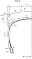
FIG. 3 is an enlarged half-cross-sectional view when the agricultural tire shown inFIG. 1 is cut along a virtual plane that passes through the center of rotation thereof. -
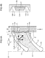
FIG. 4A is a typical view (i.e., a partial plan view) showing a tire imprint after a vehicle that has been fitted with the agricultural tire according to the exemplary embodiment has traveled over trackway soil or the like on uneven ground. -
FIG. 4B is a typical view (i.e., a partial side view) showing a tire imprint after a vehicle that has been fitted with the agricultural tire according to the exemplary embodiment has traveled over trackway soil or the like on uneven ground. -
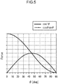
FIG. 5 is a graph showing a relationship between an angle of a surface facing in a tire rotation direction of a protruding portion forming the agricultural tire according to the exemplary embodiment, and force that is applied by the protruding portion to the trackway soil or the like on uneven ground. - Hereinafter, an embodiment (i.e., a preferred exemplary embodiment) for implementing will be described based on the drawings.
- As is shown in
FIG. 3 , anagricultural tire 10 of an exemplary embodiment is provided with a pair ofbead portions 16, asidewall portion 18, atread portion 20, acarcass 22, and abelt layer 24. - A
sidewall portion 18 is connected to each one of the pair ofbead portions 16. - The
carcass 22 is provided so as to extend in a toroidal shape between the pair ofbead portions 16. In addition, as an example, thecarcass 22 has a carcassmain body portion 22A that is disposed so as to span the distance between a pair ofbead core 26, and folded-overportions 22B that are wound around thebead cores 26. - The
belt layer 24 is provided on an outer circumference of a crown portion of thecarcass 22. - As is shown in
FIG. 1 through FIG. 3 ,lug blocks 12 are provided at thetread portion 20. Thetread portion 20 is continuous with thesidewall portions 18 on both sides. Note that portions of thetread portion 20 other than portions where thelug blocks 12 are provided are called abottom surface 20A. Thetread portion 20 is located on the outer circumferential side of thebelt layer 24. Note that, inFIG. 2 , a single-dot chain line CL shows an equatorial plane (i.e., a plane through the center in the width direction of the tread portion 20) of theagricultural tire 10. - When a vehicle (not shown in the drawings) that has been fitted with the
agricultural tires 10 is traveling on a paved road surface or the like, as a result of atop surface 12B of eachlug block 12 described below being in contact with the paved road surface, thetop surfaces 12B receive frictional force from the paved road surface. In addition, when a vehicle that has been fitted with theagricultural tires 10 is traveling over uneven ground, thelug blocks 12 generate traction on trackway soil S that is compressed byplural lug blocks 12 and thebottom surface 20A betweenplural lug blocks 12 to the front and rear in the tire circumferential direction (seeFIG. 4A and FIG. 4B ). -
Plural lug blocks 12 are provided at thetread portion 20. As is shown inFIG. 1 andFIG. 2 , as an example,plural lug blocks 12 are alternately arranged along the tire circumferential direction on both sides in the tire width direction. A longitudinal direction of eachlug block 12 is inclined with respect to the tire width direction. Moreover, as is shown inFIG. 1 , eachlug block 12 protrudes from the outer side in the tire radial direction of the tread portion, and atop surface 12B that comes into contact with the paved road surface is formed on top of eachlug block 12. When theagricultural tire 10 has been fitted onto a vehicle and this vehicle is moving forward, theagricultural tire 10 rotates in the direction shown by an arrow A (seeFIG. 1 andFIG. 2 ). Namely, when a vehicle that has been fitted with theagriculture tires 10 is moving forward, an end portion on the inner side in the tire width direction of eachlug block 12 comes into contact with the road surface before an end portion on the outer side in the tire width direction thereof. Here, the direction shown by the arrow A is an example of a tire forward rotation direction. - Moreover, as is shown in
FIG. 3 , anend portion 12A on the outer side in the tire width direction (hereinafter, referred to as an 'end portion 12A') of eachlug block 12 protrudes at an inclination on the outer side in the tire width direction of a tread end T. Here, theend portion 12A is an example of an end portion on the outer side in the tire width direction. Theend portion 12A of eachlug block 12 forms a gently sloping curved surface, and is connected by a continuous curved surface to portions on the outer side in the tire width direction of thesidewall portion 18. Note that a surface of eachlug block 12 that faces in the tire rotation direction is called aside surface 12C. Here, as is shown inFIG. 3 , the aforementioned gently sloping curved surface formed by theend portion 12A of thelug blocks 12 that dig into the ground is a curved surface in which the rate of increase in the distance between this curved surface and the equatorial plane of theagricultural tire 10 gradually decreases towards the inner side from the end portion on the outer side in the tire radial direction. - Here, the aforementioned tread end T is the outermost ground-contacting portion in the tire width direction when the
agricultural tire 10 is fitted onto a standard rim as stipulated in the 2010 edition of the Year Book published by JATMA (Japan Automobile Tire Manufacturers Association), and the internal pressure thereof is then inflated to 100% of an air pressure that corresponds to the maximum load (i.e., to the maximum air pressure) for the particular size and ply rating as prescribed in this Year Book, and the tire is then made to bear this maximum load. Note that if TRA Standards or ETRTO Standards are applied at the place of usage or at the place of manufacturing, then the present invention is made to comply with each of these Standards. - Protruding
portions 14 have a function of generating traction when a vehicle that has been fitted with theagricultural tires 10 is traveling over uneven ground. In other words, by generating traction other than the traction generated by thelug blocks 12, the protrudingportions 14 have the function of improving the traction performance of theagricultural tire 10. - As is shown in
FIG. 1 through FIG. 3 , theprotruding portions 14 protrude towards the outer side in the tire width direction from theend portions 12A. In other words, theprotruding portions 14 protrude further to the outer side in the tire width direction than the end portions on the outer side in the tire width direction of thelug blocks 12. Note that a maximum width L1 in the tire width direction of the protrudingportions 14 is not more than 10% of a width 2 x L0 in the tire width direction of thetread portion 20. - Moreover, the protruding
portions 14 also have asurface 14A that faces in the direction of the arrow A. In other words, theprotruding portions 14 have a surface that faces in the tire rotation direction. Here, thesurface 14A is an example of a surface that faces in the tire rotation direction. Note that, in the exemplary embodiment, thesurface 14A is formed, as an example, as a flat surface. Moreover, if the angle of a virtual straight line extending towards the outer side in the tire width direction is taken as 0°, then thesurface 14A is inclined 45° with respect to the tire width direction (i.e., a direction shown by an arrow C). - As is shown in
FIG. 1 andFIG. 3 , anend surface 14B on the outer side in the tire radial direction of each protrudingportion 14 is formed further to the inner side in the tire radial direction than thetop surface 12B of the lug blocks 12. Here, the end surfaces 14B are an example of an end portion on the outer side in the tire radial direction of the protrudingportions 14. In other words, an end portion on the outer side in the tire radial direction of the protrudingportions 14 is closer to the inner side in the tire radial direction than the end portion on the outer side in the tire radial direction of the lug blocks 12. Note that a distance L2 in the tire radial direction between the end portion on the outer side in the tire radial direction of each protrudingportion 14 and the end portion on the outer side in the tire radial direction of eachlug block 12 is set, as an example, to 25 mm. - Moreover, as is shown in
FIG. 1 through FIG. 3 , boundary portions B between the end portion on the inner side in the tire width direction of each protruding portion 14 (or eachsurface 14A) and the end portion on the outer side in the tire width direction of each lug block 12 (or eachside surface 12C) match each other on the front side in the tire rotation direction. - Note that, as is described above, the boundary portions B match each other on the front side in the tire rotation direction, however, as is shown in
FIG. 2 , theside surface 12C of eachlug block 12 and thesurface 14A of each protrudingportion 14 take the boundary portion B as their boundary, and are respectively inclined at mutually different angles with respect to the tire width direction (i.e., the direction of the arrow C). In other words, a corner portion is formed in the boundary portions B. Note that, if the angle of a virtual straight line extending towards the outer side in the tire width direction is taken as 0°, then the angle on the boundary portion B side of theside surface 12C is smaller than the angle of thesurface 14A (which is 45° - seeFIG. 2 ). - Next, an action of the
agricultural tire 10 of the exemplary embodiment will be described with reference made to the drawings. In the following description, firstly, action (i.e., mechanisms for generating traction and the like) generated by the lug blocks 12 and thebottom surface 20A will be described. Subsequently, an action of the protrudingportions 14, which are the principal portions of the exemplary embodiment, will be described. - The inventors of the exemplary embodiment noticed, when they observed tire tracks created after a vehicle fitted with agricultural tires traveled over trackway soil S, that the trackway soil S is more compressed in portions on the outer side of the end portions on the outer side in the tire width direction of the lug blocks 12 (see an area E2 in
FIG. 4A ). Furthermore, the present inventors also confirmed that a shear plane D1 is present in a boundary portion between the area E2 and the trackway soil S in an area E1 that is sandwiched by plural lug blocks 12 to the front and rear in the direction of the arrow A, in other words, that shear force is generated in the trackway soil S in the area E2. In addition, after the present inventors examined what type of mechanism was causing the shear force to be generated in the area E2, and then separating the traction generated by a mutual interaction with the trackway soil S into friction force traction FT and shear force traction ST, then as a result of considering the compression force in the tire radial direction generated by theend portions 12A, they confirmed the presence of reaction force F1 described below. As a result, it became clear that shear force was working in the area E2 due to the reaction force F1 and the force generated by the rotation of theagricultural tire 10. - Therefore, the protruding
portions 14 having thesurface 14A of the exemplary embodiment were provided in order to enable the shear force working in the area E2 to contribute to an improvement in the traction performance. - Next, the mechanism whereby the lug blocks 12 and the
bottom surface 20A that make up theagricultural tire 10 generated traction by mutual interaction with the trackway soil S will be described. The traction in this case can be thought of as comprising two main elements, namely, the friction force traction FT and the shear force traction ST. - The friction force traction FT is expressed by Formula (1).

- Here, µ shows a coefficient of friction between the trackway soil S and the
top surfaces 12B. PTOP shows the ground contact pressure (i.e., the contact pressure) applied to the trackway soil S by thetop surfaces 12B. ATOP shows the ground contact surface area (i.e., the contact area) of thetop surfaces 12B. - The shear force traction ST is expressed by Formula (2).

- Here, ϕ shows an internal coefficient of friction. PBottom shows the ground contact pressure (i.e., the contact pressure) applied to the trackway soil S by the
bottom surface 20A. ABottom shows the ground contact surface area (i.e., the contact area) of thebottom surface 20A. c shows an adhesive force that is determined by the viscosity and the like of the trackway soil S. Here, the internal coefficient friction represented by ϕ is a coefficient that shows the degree of friction among the trackway soil S. - Note that the shear force traction ST expressed by Formula (2) shows the single plane shear force that shears the trackway soil S that has been compressed between lug blocks 12 that are adjacent to each other in the tire rotation direction (i.e., in the direction shown by the arrow A). Here, as is shown in
FIG. 4B , the single plane shear force that shears the trackway soil S that has been compressed between mutually adjacent lug blocks 12 is the shear force on the trackway soil S that is compressed between lug blocks 12 that are adjacent to each other in the tire rotation direction (i.e., in the direction shown by the arrow A), in other words, the shear force on the trackway soil S on the inner side of a virtual line D2 that joinstop surfaces 12B of the lug blocks 12 together. By increasing this single plane shear force, it is possible to improve the traction performance of theagricultural tire 10. - Next, the force imparted to the trackway soil S on uneven ground when the lug blocks 12 forming part of the
agricultural tire 10 travel over uneven ground will be described with reference made toFIG. 4A and FIG. 4B . - When the
agricultural tire 10 rotates in the direction shown by the arrow A, the trackway soil S in the areas E1 that are sandwiched between plural lug blocks 12 to the front and rear in the direction shown by the arrow A receives force F0 from thelug block 12 on the upstream side in the direction shown by the arrow A, and is compressed in the direction shown by the arrow A. The trackway soil S sandwiched between plural lug blocks 12 to the front and rear in the direction shown by the arrow A receive force from thebottom surface 20A due to the weight of the vehicle that has been fitted with theagricultural tire 10, and is compressed in the tire radial direction. - Moreover, the
agricultural tire 10 is deformed such thatend portions 12A of the lug blocks 12 bulge in the tire width direction by the weight of the vehicle and the weight of theagricultural tire 10, and thedeformed end portions 12A compress the trackway soil S. The area E2 shown inFIG. 4A shows a portion compressed by theend portions 12A. - Here, in
FIG. 4A , θ shows an angle of inclination of an arbitrary portion of alug block 12 with respect to the tire width direction. Thus, thelug block 12 that has received the force F0 exerts a force of F on the trackway soil S in the area E1. Of this F, a force Fx which is applied in the tire width direction becomes F0 × sinθ × cosθ, while a force Fy which is applied in the tire circumferential direction becomes F0 × cos2θ. Moreover, a reaction force in the tire width direction in response to Fx (i.e., a force F1 of a force Fx that faces inwards from the outer side in the tire width direction) is generated in the trackway soil S in the area E2 as a result of the trackway soil S in the area E2 being compressed in the tire radial direction by theend portions 12A. - As is shown in
FIG. 4A , the shear plane D1 in the trackway soil S is formed in the vicinity of a virtual line connecting together end portions on the outer side in the tire width direction of the lug blocks 12 (or at a boundary between the area E1 and the area E2). Furthermore, as is shown inFIG. 4B , the shear plane D2 in the trackway soil S is formed in the vicinity of a virtual line connecting thetop surfaces 12B of the lug blocks 12 together. - In conjunction with the rotation of the
agricultural tire 10 in the direction shown by the arrow A, a reaction force having the same force as the Fy received by the trackway soil S that has been compressed by the lug blocks 12 is applied to the lug blocks 12. In other words, the lug blocks 12 generate traction via the above-described mechanism. Because of this, a vehicle that has been fitted with theagricultural tires 10 is moved in the opposite direction from the direction shown by the arrow A. - An action of the protruding
portions 14 will now be described with reference made to the drawings. - As has been described above, in order to improve the traction performance of the
agricultural tire 10, it is necessary to increase the values in Formula (2). Specifically, it is sufficient if either PBottom or ABottom, which are parameters applied in Formula (2), are increased. - Here, as is described above, in the case of the
agricultural tire 10, as is shown inFIG. 4A , the area where the trackway soil S is compressed is not only the area E1, but also the area E2 which is compressed by theend portions 12A. In addition, if the trackway soil S in the area E2 can be used for the single plane shear force, then the traction performance of theagricultural tire 10 can be improved without the surface area of thebottom surface 20A sandwiched between mutually adjacent lug blocks 12 having to be increased. - In the case of the
agricultural tire 10 of the exemplary embodiment, as is shown inFIG. 1 through FIG. 3 , plural protrudingportions 14 protrude towards the outer side in the tire width direction from theend portions 12A. In addition, the protrudingportions 14 have thesurfaces 14A that face in the tire rotation direction (i.e., in the direction shown by the arrow A). When a vehicle that has been fitted with theagricultural tires 10 is traveling over uneven ground, plural protrudingportions 14 bite into the area E2 that has been compressed by theend portions 12A. As a result, the amount of trackway soil S kicked up in the tire width direction by theagricultural tire 10 is greater than for an agricultural tire that is not provided with the protrudingportions 14. Because of this, compared with an agricultural tire that is not provided with the protrudingportions 14, the single plane shear force is greater in theagricultural tire 10. - Accordingly, according to the
agricultural tire 10 of the exemplary embodiment, it is possible to improve the traction performance on uneven ground compared to an agricultural tire that is not equipped with the protrudingportions 14. - Moreover, in the case of the
agricultural tire 10 of the exemplary embodiment, as is shown inFIG. 2 , if the angle of a virtual straight line extending towards the outer side in the tire width direction is taken as 0°, then thesurface 14A of the protrudingportions 14 is inclined 45° with respect to the tire width direction (i.e., the direction shown by the arrow C). Here, as is described above, the reaction force F1 is applied in a direction towards the inner side from the outer side in the tire width direction in the area E2 that is compressed by theend portions 12A. In addition, as is shown inFIG. 5 , when the angle of thesurface 14A with respect to the tire width direction is 45°, then the force exerted towards the outer side from the inner side in the tire width direction is at maximum. - Accordingly, when the
surface 14A of the protrudingportions 14 forming part of theagricultural tire 10 of the exemplary embodiment is inclined 45° with respect to the tire width direction, the traction performance on uneven ground can be maximized. - Note that cases in which the angle of inclination of the
surfaces 14A relative to the tire width direction is not 45° are also included as one aspect of the exemplary embodiment. For example, as is shown inFIG. 5 , provided that the angle of inclination is within a range of 45° ± 30° (i.e., not less than 15° and not more than 75°), then no matter which angle of inclination is used, compared to an angle of inclination of 45°, it is possible for traction of 50% or more of the traction provided by the protrudingportions 14 to be generated. More preferably, if the angle of inclination is within a range of 45° ± 10° (i.e., not less than 35° and not more than 55°), then no matter which angle of inclination is used, compared to an angle of inclination of 45°, it is possible for traction of 90% or more of the traction provided by the protrudingportions 14 to be generated. - Moreover, in the case of the
agricultural tire 10 of the exemplary embodiment, as is shown inFIG. 3 , the maximum width L1 in the tire width direction of the protrudingportions 14 is set to not more than 10% of a width 2 x L0 in the tire width direction of thetread portion 20. Because of this, the entire protrudingportion 14 in the tire width direction is able to kick up the trackway soil S within the area E2 compressed by theend portions 12A. Note that if the maximum width L1 in the tire width direction of the protrudingportions 14 is set to more than 10% of a width 2 x L0 in the tire width direction of thetread portion 20, then when a vehicle fitted with theagricultural tires 10 travels, for example, on a paved road surface, then it is easy for portions on the outer side in the tire width direction to strike some obstacle or other and be broken. - Moreover, as is shown in
FIG. 1 andFIG. 3 , theend portion 14B on the outer side in the tire radial direction of the protrudingportions 14 is formed further to the inner side in the tire radial direction than thetop surface 12B of the lug blocks 12. In other words, the end portion on the outer side in the tire radial direction of the protrudingportions 14 is closer to the inner side in the tire radial direction than the end portion on the outer side in the tire radial direction of the lug blocks 12. - Because of this, in the case of the
agricultural tire 10 of the exemplary embodiment, when a vehicle fitted with theagricultural tires 10 of the exemplary embodiment is traveling over a paved road surface, it is difficult for the protrudingportions 14 to come into contact with the paved road surface and be worn down. - Accordingly, according to the
agricultural tire 10 of the exemplary embodiment, it is possible to stabilize the traction performance on uneven ground over a prolonged period. - Moreover, the distance between the end portion of the protruding
portions 14 and the end portion of the lug blocks 12 in theagricultural tire 10 is set to not more than 25 mm. Because of this, when a vehicle fitted with theagricultural tires 10 of the exemplary embodiment is traveling over uneven ground, it is possible to generate traction via the protrudingportions 14. - Accordingly, according to the
agricultural tire 10 of the exemplary embodiment, it is possible to stabilize the traction performance on uneven ground over a prolonged period. - Moreover, in the case of the
agricultural tire 10 of the exemplary embodiment, as is shown inFIG. 1 through FIG. 3 , boundary portions B between the end portion on the inner side in the tire radial direction of each protruding portion 14 (or eachsurface 14A) and the end portion on the outer side in the tire radial direction of each lug block 12 (or eachside surface 12C) match each other on the front side in the direction shown by the arrow A (i.e., in the tire rotation direction). - Because of this, compared with when the boundary portions B do not match each other on the front side in the direction shown by the arrow A (i.e., in the tire rotation direction), it is possible for the protruding
portions 14 of the exemplary embodiment to apply force to those portions of the area E2 to which force is applied by the lug blocks 12. - Moreover, in the case of the
agricultural tire 10 of the exemplary embodiment, thesurface 14A and theside surface 12C are connected together at mutually different angles with the boundary portion B being taken as their boundary. In addition, if the angle of a virtual straight line extending towards the outer side in the tire width direction is taken as 0°, then the angle on the boundary portion B side of theside surface 12C is smaller than the angle of thesurface 14A (which is 45° - seeFIG. 2 ). - Accordingly, according to the
agricultural tire 10 of the exemplary embodiment, compared with a case in which the angles of thesurface 14A and theside surface 12C relative to a virtual straight line extending towards the outer side in the tire width direction are the same at the boundary portion B, then during travel over a paved road surface, it is possible to both optimize the traveling stability obtained from the lug blocks 12 and optimize the improvement in the traction performance obtained from the protrudingportions 14. -
Test 1 and Test 2 which are described below were conducted. In each test the traction performance was evaluated. -
- The test conditions for
Test 1 were as follows. - Tire size: AGR710/70R42 (Rear only)
- Internal pressure load conditions: 160 kPa, 6700 kg
- Test vehicle: JD 8530
- Field conditions: Cultivated land (BS Test course, Columbiana PG)
- The following tire was tested under the test conditions for
Test 1. - A tire used as a comparative example was a tire in which blocks that protruded in the tire width direction from the tread ends of a shoulder portion were not provided. In contrast to this, the tire of Example 1 was a tire having blocks that protruded in the tire width direction from the tread ends of a shoulder portion, wherein the protrusion width was 20 mm, and the block angle (i.e., the angle in the radial direction of the wall surface on the depressed side) was 45°.
- In the case of the tire of the comparative example, compared to a traction value when the tire was brand new (i.e., when the amount of wear was 0%) of 100, the traction value when worn (i.e., when the amount of wear was 50%) was 85. In contrast to this, in the case of the tire of Example 1, compared to a traction value when the tire was brand new (i.e., when the amount of wear was 0%) of 105, the traction value when worn (i.e., when the amount of wear was 50%) was 91.
- The tire of Example 1 is one aspect of the tire of the exemplary embodiment. From the results obtained from
Test 1, it was found that, when the tires had been used and were worn, compared with the tire of the comparative example, the tire of Example 1 had a superior traction performance. -
- The test conditions for Test 2 were as follows.
- Tire size: AGR710/70R42 (Rear only)
- Internal pressure load conditions: 160 kPa, 6700 kg
- Test vehicle: JD 8530
- Field conditions: Cultivated land (BS Test course, Columbiana PG)
- The following tire was tested under the test conditions for Test 2.
- The tire of Example 2 was a tire having blocks that protruded in the tire width direction from the tread ends of a shoulder portion, wherein the groove depth was reduced 30% compared to the tire of the comparative example, the protrusion width was 20 mm, and the block angle (i.e., the angle in the radial direction of the wall surface on the depressed side) was 45°.
- In the case of the tire of the comparative example, as is described above, the traction value when the tire was brand new (i.e., when the amount of wear was 0%) was 100. In contrast to this, in the case of the tire of Example 1, the traction value when the tire was brand new (i.e., when the amount of wear was 0%) was 100.
- The tire of Example 2 is one aspect of the tire of the exemplary embodiment. From the results obtained from Test 2, it was found that, when the tires were new, compared with the tire of the comparative example, in spite of the groove depth being reduced 30%, the tire of Example 2 had an equivalent traction performance.
- It was found that, in the field, the tire of Example 1 exhibited a superior traction performance when new and a superior traction performance when worn (i.e., after being worn). Furthermore, in spite of the groove depth being reduced 30%, in the field, the tire of Example 2 exhibits an equivalent traction performance when new compared to a tire without any blocks. As a consequence of this, because the tire of Example 1 has a superior traction performance when worn, the slip ratio when worn is reduced. Moreover, because the tire of Example 2 exhibits an equivalent traction performance when new as a tire having no blocks, the slip ratio when new is also reduced. Because of this, it was found that the tire of Example 2 is excellent from the viewpoint of fuel consumption when traveling in the field as well. As has been described above, according to the tires of Examples 1 and 2, it was found that it is possible to provide an agricultural tire that has superior traction performance and fuel consumption in the field, while maintaining traveling stability on normal roads (i.e., on paved roads).
- Exemplary embodiments of the present invention have described in detail above using a specific exemplary embodiment thereof, however, additional exemplary embodiments are also possible. For example, in the specific exemplary embodiment, the
surface 14A of the protrudingportions 14 that faces in the tire rotation direction is described as a flat surface. However, provided that thesurface 14A has a function of improving the traction performance, then thesurface 14A of an additional embodiment does not need to be flat. For example, thesurface 14A of an additional embodiment may be a curved surface, or a spherical surface, or another type of surface. In this case, if the angle of this curved surface, spherical surface, or other type of surface relative to a virtual line extending towards an outer side in the tire width direction is set as 0°, then an angle between a tangent of this curved surface, spherical surface, or other type of surface relative to a virtual line extending towards an outer side in the tire width direction may be set to not less than 35° and not more than 55°. - Priority is claimed on Japanese Patent Application No.
2014-114156, filed June 2, 2014
Claims (5)
- An agricultural tire comprising:a plurality of lug blocks that are provided at a tread portion; andprotruding portions that protrude towards an outer side in a tire width direction from an end portion on the outer side in the tire width direction of the lug blocks, and that have a surface that, if an angle of a virtual straight line extending towards the outer side in the tire width direction is taken as 0°, faces a tire rotation direction at an angle of not less than 35° and not more than 55°.
- The agricultural tire according to claim 1, wherein an end portion on an outer side in a tire radial direction of the protruding portions is formed further to an inner side in the tire radial direction than an end portion on the outer side in the tire radial direction of the lug blocks.
- The agricultural tire according to claim 2, wherein a distance in the tire radial direction between the end portion on the outer side in the tire radial direction of the protruding portions and the end portion on the outer side in the tire radial direction of the lug blocks is not more than 25 mm.
- The agricultural tire according to any one of claims 1 to 3, wherein a maximum width in the tire width direction of the protruding portions is not more than 10% of a width in the tire width direction of the tread portion.
- The agricultural tire according to any one of claims 1 to 4, wherein boundary portions between an end portion on an inner side in the tire width direction of the protruding portions and the end portion on the outer side in the tire width direction of the lug blocks match each other on a front side in the tire rotation direction.
Applications Claiming Priority (2)
| Application Number | Priority Date | Filing Date | Title |
|---|---|---|---|
| JP2014114156A JP6284829B2 (en) | 2014-06-02 | 2014-06-02 | Agricultural tires |
| PCT/JP2015/060379 WO2015186419A1 (en) | 2014-06-02 | 2015-04-01 | Agriculture tire |
Publications (3)
| Publication Number | Publication Date |
|---|---|
| EP3150405A1 true EP3150405A1 (en) | 2017-04-05 |
| EP3150405A4 EP3150405A4 (en) | 2017-07-05 |
| EP3150405B1 EP3150405B1 (en) | 2020-05-06 |
Family
ID=54766500
Family Applications (1)
| Application Number | Title | Priority Date | Filing Date |
|---|---|---|---|
| EP15802929.8A Not-in-force EP3150405B1 (en) | 2014-06-02 | 2015-04-01 | Agriculture tire |
Country Status (5)
| Country | Link |
|---|---|
| US (1) | US20170190219A1 (en) |
| EP (1) | EP3150405B1 (en) |
| JP (1) | JP6284829B2 (en) |
| CN (1) | CN106457917B (en) |
| WO (1) | WO2015186419A1 (en) |
Cited By (3)
| Publication number | Priority date | Publication date | Assignee | Title |
|---|---|---|---|---|
| FR3094271A1 (en) * | 2019-03-29 | 2020-10-02 | Compagnie Generale Des Etablissements Michelin | Agricultural vehicle tire comprising a tread |
| EP3738791A1 (en) * | 2019-05-14 | 2020-11-18 | Nokian Raskaat Renkaat Oy | Pneumatic vehicle tyre for forestry use |
| RU2798322C2 (en) * | 2019-03-29 | 2023-06-21 | Компани Женераль Дэз Этаблиссман Мишлен | Tire for agricultural vehicle, tire containing protector |
Families Citing this family (2)
| Publication number | Priority date | Publication date | Assignee | Title |
|---|---|---|---|---|
| JP6650938B2 (en) * | 2015-06-18 | 2020-02-19 | 株式会社ブリヂストン | tire |
| CN107487130A (en) * | 2017-08-11 | 2017-12-19 | 朱晓 | A kind of good Agricultural tire of protection effect |
Family Cites Families (21)
| Publication number | Priority date | Publication date | Assignee | Title |
|---|---|---|---|---|
| AU503292B2 (en) * | 1976-06-11 | 1979-08-30 | Societa Pneumatici Pirelli S.P.A. | Pneumatic tire with lugged thread |
| FR2367627A1 (en) * | 1976-10-12 | 1978-05-12 | Kleber Colombes | TIRE FOR DRIVE WHEELS OF AGRICULTURAL TRACTORS OR SIMILAR MACHINERY |
| FR2367626A1 (en) * | 1976-10-13 | 1978-05-12 | Kleber Colombes | TIRE FOR AGRICULTURAL TRACTOR DRIVE WHEEL OR SIMILAR APPLICATIONS |
| US4480672A (en) * | 1983-07-11 | 1984-11-06 | The B. F. Goodrich Company | Antivibration tractor tire |
| JPH02204102A (en) * | 1989-02-03 | 1990-08-14 | Bridgestone Corp | Pneumatic tire for agriculture |
| US5016696A (en) * | 1989-10-11 | 1991-05-21 | The Goodyear Tire & Rubber Company | Self-cleaning tire tread |
| JP2909163B2 (en) * | 1990-07-23 | 1999-06-23 | 株式会社ブリヂストン | Driving wheel deep groove tire for agricultural tractor |
| JPH09156322A (en) * | 1995-12-06 | 1997-06-17 | Bridgestone Corp | Traveling body having lug |
| US6533007B1 (en) * | 2000-03-02 | 2003-03-18 | Mcmannis Lee A. | Tire having sidewall extensions at opposite ends of each tread element |
| US7497240B2 (en) * | 2001-12-19 | 2009-03-03 | The Goodyear Tire & Rubber Company | Tire including projections having sides of unequal length and an undercut extending beneath the apex |
| JP4202168B2 (en) * | 2003-03-28 | 2008-12-24 | 東洋ゴム工業株式会社 | Pneumatic radial tire |
| JP2006273052A (en) * | 2005-03-28 | 2006-10-12 | Bridgestone Corp | Pneumatic tire |
| JP2007168520A (en) * | 2005-12-20 | 2007-07-05 | Sumitomo Rubber Ind Ltd | Tire with lug |
| JP2008062846A (en) * | 2006-09-08 | 2008-03-21 | Sumitomo Rubber Ind Ltd | Running body with lugs |
| JP5222736B2 (en) * | 2007-02-09 | 2013-06-26 | 株式会社ブリヂストン | Pneumatic tire |
| FR2916682B1 (en) * | 2007-06-01 | 2011-09-16 | Michelin Soc Tech | TIRE COMPRISING A DEVIATOR DEVICE FOR PROJECTIONS. |
| US8434534B2 (en) * | 2007-08-24 | 2013-05-07 | Michelin Recherche Et Technique | Tire having sidewall protection |
| JP2010047161A (en) * | 2008-08-22 | 2010-03-04 | Sumitomo Rubber Ind Ltd | Wheel for agricultural use |
| JP4989755B2 (en) * | 2010-07-09 | 2012-08-01 | 住友ゴム工業株式会社 | Pneumatic tire |
| JP5687456B2 (en) * | 2010-08-26 | 2015-03-18 | 株式会社ブリヂストン | tire |
| JP5689631B2 (en) * | 2010-09-01 | 2015-03-25 | 株式会社ブリヂストン | Agricultural tires |
-
2014
- 2014-06-02 JP JP2014114156A patent/JP6284829B2/en not_active Expired - Fee Related
-
2015
- 2015-04-01 US US15/315,186 patent/US20170190219A1/en not_active Abandoned
- 2015-04-01 WO PCT/JP2015/060379 patent/WO2015186419A1/en not_active Ceased
- 2015-04-01 EP EP15802929.8A patent/EP3150405B1/en not_active Not-in-force
- 2015-04-01 CN CN201580029161.6A patent/CN106457917B/en not_active Expired - Fee Related
Cited By (5)
| Publication number | Priority date | Publication date | Assignee | Title |
|---|---|---|---|---|
| FR3094271A1 (en) * | 2019-03-29 | 2020-10-02 | Compagnie Generale Des Etablissements Michelin | Agricultural vehicle tire comprising a tread |
| WO2020201027A1 (en) * | 2019-03-29 | 2020-10-08 | Compagnie Generale Des Etablissements Michelin | Tyre for an agricultural vehicle, the tyre comprising a tread |
| RU2798322C2 (en) * | 2019-03-29 | 2023-06-21 | Компани Женераль Дэз Этаблиссман Мишлен | Tire for agricultural vehicle, tire containing protector |
| US12145406B2 (en) | 2019-03-29 | 2024-11-19 | Compagnie Generale Des Etablissements Michelin | Tire for an agricultural vehicle, the tire comprising a tread |
| EP3738791A1 (en) * | 2019-05-14 | 2020-11-18 | Nokian Raskaat Renkaat Oy | Pneumatic vehicle tyre for forestry use |
Also Published As
| Publication number | Publication date |
|---|---|
| JP6284829B2 (en) | 2018-02-28 |
| EP3150405B1 (en) | 2020-05-06 |
| US20170190219A1 (en) | 2017-07-06 |
| EP3150405A4 (en) | 2017-07-05 |
| CN106457917B (en) | 2018-12-21 |
| CN106457917A (en) | 2017-02-22 |
| WO2015186419A1 (en) | 2015-12-10 |
| JP2015227137A (en) | 2015-12-17 |
Similar Documents
| Publication | Publication Date | Title |
|---|---|---|
| JP5337199B2 (en) | Motorcycle tires for running on rough terrain | |
| US8887778B2 (en) | Motorcycle tire for off-road traveling | |
| EP3000622B1 (en) | Pneumatic tire | |
| JP5039191B2 (en) | Motorcycle tires for running on rough terrain | |
| JP5174142B2 (en) | Motorcycle tires for running on rough terrain | |
| CN104108289B (en) | Pneumatic tire | |
| CN104972844B (en) | Pneumatic tire | |
| JP4312226B2 (en) | Pneumatic tire for running on rough terrain | |
| JP2006111091A (en) | Heavy duty radial tire | |
| CN104981362B (en) | Pneumatic tire | |
| CN105492223A (en) | Pneumatic tire | |
| EP3150405B1 (en) | Agriculture tire | |
| JP7119634B2 (en) | pneumatic tire | |
| CN103522843A (en) | Pneumatic tire for rough terrain | |
| CN103442909B (en) | Air-inflation tyre | |
| CN103802609B (en) | Pneumatic tyre | |
| WO2021085004A1 (en) | Pneumatic tire | |
| US20200207156A1 (en) | Off-road tyre | |
| JP6949649B2 (en) | tire | |
| US11040579B2 (en) | Pneumatic tire and stud pin | |
| EP3312025B1 (en) | Tire | |
| JP6585472B2 (en) | Pneumatic tire | |
| CN106240243B (en) | Pneumatic tire | |
| CN114919339B (en) | A pneumatic tire for all-terrain vehicles used for rock climbing and its tread pattern structure | |
| CN109843606B (en) | Pneumatic tires |
Legal Events
| Date | Code | Title | Description |
|---|---|---|---|
| STAA | Information on the status of an ep patent application or granted ep patent |
Free format text: STATUS: THE INTERNATIONAL PUBLICATION HAS BEEN MADE |
|
| PUAI | Public reference made under article 153(3) epc to a published international application that has entered the european phase |
Free format text: ORIGINAL CODE: 0009012 |
|
| STAA | Information on the status of an ep patent application or granted ep patent |
Free format text: STATUS: REQUEST FOR EXAMINATION WAS MADE |
|
| 17P | Request for examination filed |
Effective date: 20161202 |
|
| AK | Designated contracting states |
Kind code of ref document: A1 Designated state(s): AL AT BE BG CH CY CZ DE DK EE ES FI FR GB GR HR HU IE IS IT LI LT LU LV MC MK MT NL NO PL PT RO RS SE SI SK SM TR |
|
| AX | Request for extension of the european patent |
Extension state: BA ME |
|
| A4 | Supplementary search report drawn up and despatched |
Effective date: 20170602 |
|
| RIC1 | Information provided on ipc code assigned before grant |
Ipc: B60C 11/03 20060101AFI20170529BHEP |
|
| DAV | Request for validation of the european patent (deleted) | ||
| DAX | Request for extension of the european patent (deleted) | ||
| REG | Reference to a national code |
Ref country code: DE Ref legal event code: R079 Ref document number: 602015052387 Country of ref document: DE Free format text: PREVIOUS MAIN CLASS: B60C0011030000 Ipc: B60C0011010000 |
|
| STAA | Information on the status of an ep patent application or granted ep patent |
Free format text: STATUS: EXAMINATION IS IN PROGRESS |
|
| RIC1 | Information provided on ipc code assigned before grant |
Ipc: B60C 11/03 20060101ALI20180319BHEP Ipc: B60C 11/01 20060101AFI20180319BHEP |
|
| 17Q | First examination report despatched |
Effective date: 20180423 |
|
| GRAP | Despatch of communication of intention to grant a patent |
Free format text: ORIGINAL CODE: EPIDOSNIGR1 |
|
| STAA | Information on the status of an ep patent application or granted ep patent |
Free format text: STATUS: GRANT OF PATENT IS INTENDED |
|
| INTG | Intention to grant announced |
Effective date: 20191204 |
|
| GRAS | Grant fee paid |
Free format text: ORIGINAL CODE: EPIDOSNIGR3 |
|
| GRAA | (expected) grant |
Free format text: ORIGINAL CODE: 0009210 |
|
| STAA | Information on the status of an ep patent application or granted ep patent |
Free format text: STATUS: THE PATENT HAS BEEN GRANTED |
|
| AK | Designated contracting states |
Kind code of ref document: B1 Designated state(s): AL AT BE BG CH CY CZ DE DK EE ES FI FR GB GR HR HU IE IS IT LI LT LU LV MC MK MT NL NO PL PT RO RS SE SI SK SM TR |
|
| REG | Reference to a national code |
Ref country code: GB Ref legal event code: FG4D |
|
| REG | Reference to a national code |
Ref country code: CH Ref legal event code: EP Ref country code: AT Ref legal event code: REF Ref document number: 1266178 Country of ref document: AT Kind code of ref document: T Effective date: 20200515 |
|
| REG | Reference to a national code |
Ref country code: DE Ref legal event code: R096 Ref document number: 602015052387 Country of ref document: DE |
|
| REG | Reference to a national code |
Ref country code: IE Ref legal event code: FG4D |
|
| REG | Reference to a national code |
Ref country code: LT Ref legal event code: MG4D |
|
| REG | Reference to a national code |
Ref country code: NL Ref legal event code: MP Effective date: 20200506 |
|
| PG25 | Lapsed in a contracting state [announced via postgrant information from national office to epo] |
Ref country code: LT Free format text: LAPSE BECAUSE OF FAILURE TO SUBMIT A TRANSLATION OF THE DESCRIPTION OR TO PAY THE FEE WITHIN THE PRESCRIBED TIME-LIMIT Effective date: 20200506 Ref country code: GR Free format text: LAPSE BECAUSE OF FAILURE TO SUBMIT A TRANSLATION OF THE DESCRIPTION OR TO PAY THE FEE WITHIN THE PRESCRIBED TIME-LIMIT Effective date: 20200807 Ref country code: NO Free format text: LAPSE BECAUSE OF FAILURE TO SUBMIT A TRANSLATION OF THE DESCRIPTION OR TO PAY THE FEE WITHIN THE PRESCRIBED TIME-LIMIT Effective date: 20200806 Ref country code: SE Free format text: LAPSE BECAUSE OF FAILURE TO SUBMIT A TRANSLATION OF THE DESCRIPTION OR TO PAY THE FEE WITHIN THE PRESCRIBED TIME-LIMIT Effective date: 20200506 Ref country code: IS Free format text: LAPSE BECAUSE OF FAILURE TO SUBMIT A TRANSLATION OF THE DESCRIPTION OR TO PAY THE FEE WITHIN THE PRESCRIBED TIME-LIMIT Effective date: 20200906 Ref country code: PT Free format text: LAPSE BECAUSE OF FAILURE TO SUBMIT A TRANSLATION OF THE DESCRIPTION OR TO PAY THE FEE WITHIN THE PRESCRIBED TIME-LIMIT Effective date: 20200907 Ref country code: FI Free format text: LAPSE BECAUSE OF FAILURE TO SUBMIT A TRANSLATION OF THE DESCRIPTION OR TO PAY THE FEE WITHIN THE PRESCRIBED TIME-LIMIT Effective date: 20200506 |
|
| PG25 | Lapsed in a contracting state [announced via postgrant information from national office to epo] |
Ref country code: HR Free format text: LAPSE BECAUSE OF FAILURE TO SUBMIT A TRANSLATION OF THE DESCRIPTION OR TO PAY THE FEE WITHIN THE PRESCRIBED TIME-LIMIT Effective date: 20200506 Ref country code: LV Free format text: LAPSE BECAUSE OF FAILURE TO SUBMIT A TRANSLATION OF THE DESCRIPTION OR TO PAY THE FEE WITHIN THE PRESCRIBED TIME-LIMIT Effective date: 20200506 Ref country code: BG Free format text: LAPSE BECAUSE OF FAILURE TO SUBMIT A TRANSLATION OF THE DESCRIPTION OR TO PAY THE FEE WITHIN THE PRESCRIBED TIME-LIMIT Effective date: 20200806 Ref country code: RS Free format text: LAPSE BECAUSE OF FAILURE TO SUBMIT A TRANSLATION OF THE DESCRIPTION OR TO PAY THE FEE WITHIN THE PRESCRIBED TIME-LIMIT Effective date: 20200506 |
|
| REG | Reference to a national code |
Ref country code: AT Ref legal event code: MK05 Ref document number: 1266178 Country of ref document: AT Kind code of ref document: T Effective date: 20200506 |
|
| PG25 | Lapsed in a contracting state [announced via postgrant information from national office to epo] |
Ref country code: AL Free format text: LAPSE BECAUSE OF FAILURE TO SUBMIT A TRANSLATION OF THE DESCRIPTION OR TO PAY THE FEE WITHIN THE PRESCRIBED TIME-LIMIT Effective date: 20200506 Ref country code: NL Free format text: LAPSE BECAUSE OF FAILURE TO SUBMIT A TRANSLATION OF THE DESCRIPTION OR TO PAY THE FEE WITHIN THE PRESCRIBED TIME-LIMIT Effective date: 20200506 |
|
| PG25 | Lapsed in a contracting state [announced via postgrant information from national office to epo] |
Ref country code: SM Free format text: LAPSE BECAUSE OF FAILURE TO SUBMIT A TRANSLATION OF THE DESCRIPTION OR TO PAY THE FEE WITHIN THE PRESCRIBED TIME-LIMIT Effective date: 20200506 Ref country code: EE Free format text: LAPSE BECAUSE OF FAILURE TO SUBMIT A TRANSLATION OF THE DESCRIPTION OR TO PAY THE FEE WITHIN THE PRESCRIBED TIME-LIMIT Effective date: 20200506 Ref country code: RO Free format text: LAPSE BECAUSE OF FAILURE TO SUBMIT A TRANSLATION OF THE DESCRIPTION OR TO PAY THE FEE WITHIN THE PRESCRIBED TIME-LIMIT Effective date: 20200506 Ref country code: ES Free format text: LAPSE BECAUSE OF FAILURE TO SUBMIT A TRANSLATION OF THE DESCRIPTION OR TO PAY THE FEE WITHIN THE PRESCRIBED TIME-LIMIT Effective date: 20200506 Ref country code: CZ Free format text: LAPSE BECAUSE OF FAILURE TO SUBMIT A TRANSLATION OF THE DESCRIPTION OR TO PAY THE FEE WITHIN THE PRESCRIBED TIME-LIMIT Effective date: 20200506 Ref country code: AT Free format text: LAPSE BECAUSE OF FAILURE TO SUBMIT A TRANSLATION OF THE DESCRIPTION OR TO PAY THE FEE WITHIN THE PRESCRIBED TIME-LIMIT Effective date: 20200506 Ref country code: DK Free format text: LAPSE BECAUSE OF FAILURE TO SUBMIT A TRANSLATION OF THE DESCRIPTION OR TO PAY THE FEE WITHIN THE PRESCRIBED TIME-LIMIT Effective date: 20200506 |
|
| REG | Reference to a national code |
Ref country code: DE Ref legal event code: R097 Ref document number: 602015052387 Country of ref document: DE |
|
| PG25 | Lapsed in a contracting state [announced via postgrant information from national office to epo] |
Ref country code: PL Free format text: LAPSE BECAUSE OF FAILURE TO SUBMIT A TRANSLATION OF THE DESCRIPTION OR TO PAY THE FEE WITHIN THE PRESCRIBED TIME-LIMIT Effective date: 20200506 Ref country code: SK Free format text: LAPSE BECAUSE OF FAILURE TO SUBMIT A TRANSLATION OF THE DESCRIPTION OR TO PAY THE FEE WITHIN THE PRESCRIBED TIME-LIMIT Effective date: 20200506 |
|
| PLBE | No opposition filed within time limit |
Free format text: ORIGINAL CODE: 0009261 |
|
| STAA | Information on the status of an ep patent application or granted ep patent |
Free format text: STATUS: NO OPPOSITION FILED WITHIN TIME LIMIT |
|
| 26N | No opposition filed |
Effective date: 20210209 |
|
| PG25 | Lapsed in a contracting state [announced via postgrant information from national office to epo] |
Ref country code: SI Free format text: LAPSE BECAUSE OF FAILURE TO SUBMIT A TRANSLATION OF THE DESCRIPTION OR TO PAY THE FEE WITHIN THE PRESCRIBED TIME-LIMIT Effective date: 20200506 |
|
| PG25 | Lapsed in a contracting state [announced via postgrant information from national office to epo] |
Ref country code: MC Free format text: LAPSE BECAUSE OF FAILURE TO SUBMIT A TRANSLATION OF THE DESCRIPTION OR TO PAY THE FEE WITHIN THE PRESCRIBED TIME-LIMIT Effective date: 20200506 |
|
| GBPC | Gb: european patent ceased through non-payment of renewal fee |
Effective date: 20210401 |
|
| PG25 | Lapsed in a contracting state [announced via postgrant information from national office to epo] |
Ref country code: LU Free format text: LAPSE BECAUSE OF NON-PAYMENT OF DUE FEES Effective date: 20210401 |
|
| REG | Reference to a national code |
Ref country code: BE Ref legal event code: MM Effective date: 20210430 |
|
| PG25 | Lapsed in a contracting state [announced via postgrant information from national office to epo] |
Ref country code: CH Free format text: LAPSE BECAUSE OF NON-PAYMENT OF DUE FEES Effective date: 20210430 Ref country code: LI Free format text: LAPSE BECAUSE OF NON-PAYMENT OF DUE FEES Effective date: 20210430 Ref country code: GB Free format text: LAPSE BECAUSE OF NON-PAYMENT OF DUE FEES Effective date: 20210401 |
|
| PG25 | Lapsed in a contracting state [announced via postgrant information from national office to epo] |
Ref country code: IE Free format text: LAPSE BECAUSE OF NON-PAYMENT OF DUE FEES Effective date: 20210401 |
|
| REG | Reference to a national code |
Ref country code: DE Ref legal event code: R082 Ref document number: 602015052387 Country of ref document: DE Representative=s name: BARDEHLE PAGENBERG PARTNERSCHAFT MBB PATENTANW, DE |
|
| PG25 | Lapsed in a contracting state [announced via postgrant information from national office to epo] |
Ref country code: BE Free format text: LAPSE BECAUSE OF NON-PAYMENT OF DUE FEES Effective date: 20210430 |
|
| PGFP | Annual fee paid to national office [announced via postgrant information from national office to epo] |
Ref country code: IT Payment date: 20220420 Year of fee payment: 8 Ref country code: FR Payment date: 20220421 Year of fee payment: 8 Ref country code: DE Payment date: 20220420 Year of fee payment: 8 |
|
| PG25 | Lapsed in a contracting state [announced via postgrant information from national office to epo] |
Ref country code: HU Free format text: LAPSE BECAUSE OF FAILURE TO SUBMIT A TRANSLATION OF THE DESCRIPTION OR TO PAY THE FEE WITHIN THE PRESCRIBED TIME-LIMIT; INVALID AB INITIO Effective date: 20150401 |
|
| PG25 | Lapsed in a contracting state [announced via postgrant information from national office to epo] |
Ref country code: CY Free format text: LAPSE BECAUSE OF FAILURE TO SUBMIT A TRANSLATION OF THE DESCRIPTION OR TO PAY THE FEE WITHIN THE PRESCRIBED TIME-LIMIT Effective date: 20200506 |
|
| P01 | Opt-out of the competence of the unified patent court (upc) registered |
Effective date: 20230531 |
|
| REG | Reference to a national code |
Ref country code: DE Ref legal event code: R119 Ref document number: 602015052387 Country of ref document: DE |
|
| PG25 | Lapsed in a contracting state [announced via postgrant information from national office to epo] |
Ref country code: FR Free format text: LAPSE BECAUSE OF NON-PAYMENT OF DUE FEES Effective date: 20230430 Ref country code: DE Free format text: LAPSE BECAUSE OF NON-PAYMENT OF DUE FEES Effective date: 20231103 |
|
| PG25 | Lapsed in a contracting state [announced via postgrant information from national office to epo] |
Ref country code: MK Free format text: LAPSE BECAUSE OF FAILURE TO SUBMIT A TRANSLATION OF THE DESCRIPTION OR TO PAY THE FEE WITHIN THE PRESCRIBED TIME-LIMIT Effective date: 20200506 Ref country code: IT Free format text: LAPSE BECAUSE OF NON-PAYMENT OF DUE FEES Effective date: 20230401 |
|
| PG25 | Lapsed in a contracting state [announced via postgrant information from national office to epo] |
Ref country code: TR Free format text: LAPSE BECAUSE OF FAILURE TO SUBMIT A TRANSLATION OF THE DESCRIPTION OR TO PAY THE FEE WITHIN THE PRESCRIBED TIME-LIMIT Effective date: 20200506 |
|
| PG25 | Lapsed in a contracting state [announced via postgrant information from national office to epo] |
Ref country code: MT Free format text: LAPSE BECAUSE OF FAILURE TO SUBMIT A TRANSLATION OF THE DESCRIPTION OR TO PAY THE FEE WITHIN THE PRESCRIBED TIME-LIMIT Effective date: 20200506 |