EP3150077A1 - Schuhoberteil - Google Patents
Schuhoberteil Download PDFInfo
- Publication number
- EP3150077A1 EP3150077A1 EP14893246.0A EP14893246A EP3150077A1 EP 3150077 A1 EP3150077 A1 EP 3150077A1 EP 14893246 A EP14893246 A EP 14893246A EP 3150077 A1 EP3150077 A1 EP 3150077A1
- Authority
- EP
- European Patent Office
- Prior art keywords
- foot
- string portions
- string
- panels
- upper according
- Prior art date
- Legal status (The legal status is an assumption and is not a legal conclusion. Google has not performed a legal analysis and makes no representation as to the accuracy of the status listed.)
- Granted
Links
Images


Classifications
-
- A—HUMAN NECESSITIES
- A43—FOOTWEAR
- A43B—CHARACTERISTIC FEATURES OF FOOTWEAR; PARTS OF FOOTWEAR
- A43B23/00—Uppers; Boot legs; Stiffeners; Other single parts of footwear
- A43B23/02—Uppers; Boot legs
- A43B23/0245—Uppers; Boot legs characterised by the constructive form
- A43B23/028—Resilient uppers, e.g. shock absorbing
-
- A—HUMAN NECESSITIES
- A43—FOOTWEAR
- A43B—CHARACTERISTIC FEATURES OF FOOTWEAR; PARTS OF FOOTWEAR
- A43B1/00—Footwear characterised by the material
- A43B1/02—Footwear characterised by the material made of fibres or fabrics made therefrom
- A43B1/04—Footwear characterised by the material made of fibres or fabrics made therefrom braided, knotted, knitted or crocheted
-
- A—HUMAN NECESSITIES
- A43—FOOTWEAR
- A43B—CHARACTERISTIC FEATURES OF FOOTWEAR; PARTS OF FOOTWEAR
- A43B23/00—Uppers; Boot legs; Stiffeners; Other single parts of footwear
- A43B23/02—Uppers; Boot legs
-
- A—HUMAN NECESSITIES
- A43—FOOTWEAR
- A43B—CHARACTERISTIC FEATURES OF FOOTWEAR; PARTS OF FOOTWEAR
- A43B23/00—Uppers; Boot legs; Stiffeners; Other single parts of footwear
- A43B23/02—Uppers; Boot legs
- A43B23/0205—Uppers; Boot legs characterised by the material
- A43B23/0215—Plastics or artificial leather
-
- A—HUMAN NECESSITIES
- A43—FOOTWEAR
- A43B—CHARACTERISTIC FEATURES OF FOOTWEAR; PARTS OF FOOTWEAR
- A43B23/00—Uppers; Boot legs; Stiffeners; Other single parts of footwear
- A43B23/02—Uppers; Boot legs
- A43B23/0205—Uppers; Boot legs characterised by the material
- A43B23/0235—Different layers of different material
-
- A—HUMAN NECESSITIES
- A43—FOOTWEAR
- A43B—CHARACTERISTIC FEATURES OF FOOTWEAR; PARTS OF FOOTWEAR
- A43B23/00—Uppers; Boot legs; Stiffeners; Other single parts of footwear
- A43B23/02—Uppers; Boot legs
- A43B23/0245—Uppers; Boot legs characterised by the constructive form
- A43B23/026—Laminated layers
-
- A—HUMAN NECESSITIES
- A43—FOOTWEAR
- A43B—CHARACTERISTIC FEATURES OF FOOTWEAR; PARTS OF FOOTWEAR
- A43B23/00—Uppers; Boot legs; Stiffeners; Other single parts of footwear
- A43B23/02—Uppers; Boot legs
- A43B23/0245—Uppers; Boot legs characterised by the constructive form
- A43B23/0265—Uppers; Boot legs characterised by the constructive form having different properties in different directions
- A43B23/027—Uppers; Boot legs characterised by the constructive form having different properties in different directions with a part of the upper particularly flexible, e.g. permitting articulation or torsion
-
- A—HUMAN NECESSITIES
- A43—FOOTWEAR
- A43B—CHARACTERISTIC FEATURES OF FOOTWEAR; PARTS OF FOOTWEAR
- A43B23/00—Uppers; Boot legs; Stiffeners; Other single parts of footwear
- A43B23/02—Uppers; Boot legs
- A43B23/0245—Uppers; Boot legs characterised by the constructive form
- A43B23/0265—Uppers; Boot legs characterised by the constructive form having different properties in different directions
- A43B23/0275—Uppers; Boot legs characterised by the constructive form having different properties in different directions with a part of the upper particularly rigid, e.g. resisting articulation or torsion
-
- A—HUMAN NECESSITIES
- A43—FOOTWEAR
- A43B—CHARACTERISTIC FEATURES OF FOOTWEAR; PARTS OF FOOTWEAR
- A43B5/00—Footwear for sporting purposes
- A43B5/06—Running shoes; Track shoes
-
- A—HUMAN NECESSITIES
- A43—FOOTWEAR
- A43B—CHARACTERISTIC FEATURES OF FOOTWEAR; PARTS OF FOOTWEAR
- A43B7/00—Footwear with health or hygienic arrangements
- A43B7/06—Footwear with health or hygienic arrangements ventilated
- A43B7/08—Footwear with health or hygienic arrangements ventilated with air-holes, with or without closures
- A43B7/084—Footwear with health or hygienic arrangements ventilated with air-holes, with or without closures characterised by the location of the holes
- A43B7/085—Footwear with health or hygienic arrangements ventilated with air-holes, with or without closures characterised by the location of the holes in the upper
-
- A—HUMAN NECESSITIES
- A43—FOOTWEAR
- A43C—FASTENINGS OR ATTACHMENTS OF FOOTWEAR; LACES IN GENERAL
- A43C1/00—Shoe lacing fastenings
- A43C1/04—Shoe lacing fastenings with rings or loops
Definitions
- the present invention relates to an upper of a shoe.
- the upper In sports such as tennis, volleyball and soccer, a player needs to perform the direction-changing action and the braking action many times. Due to such characteristics of these sports, the upper needs to be stable in the transverse direction. Therefore, the stability of the upper has been ensured for present-day athletic shoes by using an artificial material having a high rigidity or a polyurethane-made resin material.
- an upper of the present invention includes:
- non-elongatable means to include non-stretchable string portions that do not either stretch or shrink, and include string portions that do not substantially stretch past a predetermined length (by forces to be applied while the shoe is worn) but that are capable of shrinking from the predetermined length.
- String-shaped string portion means something that is thicker than a sewing thread and thinner than a rope.
- longitudinal direction Y means to include the horizontal direction parallel to the longitudinal axis of the foot and directions that are inclined upward or downward and/or medially or laterally with respect to the horizontal direction.
- string portions placed between a pair of panels 11 will serve to reduce the weight of the upper.
- the string portions as compared with an ordinary upper member having a planar structure, will more easily twist and will more easily exhibit a deformation of shrinking by being bent. Therefore, the upper will easily deform in conformity to a shrinking deformation of the foot, or the like, following a deformation of the foot. Thus, the fitting quality will improve.
- the non-elongatable string portions When the foot is urged to slip, inside the upper, toward the medial side or the lateral side, the non-elongatable string portions will not elongate (lengthen, stretch) past the predetermined length and will support the side surface of the medial side and the lateral side of the foot. This will realize a good stability.
- the string portions 10 are set so that the string portions 10 are freely displaceable and/or deformable in a transverse direction X of the foot and/or in an up-down direction. That is, the string portions 10 are in at least one or more state, of the state in which the string portions 10 can be easily moved or deformed in the transverse direction X of the foot or the state in which the string portions 10 can be easily moved or deformed in the up-down direction.
- up-down direction means to include the vertical direction and directions that are inclined forward or rearward and/or medially or laterally with respect to the vertical direction, and means to include the direction perpendicular to the direction in which the string portions 10 extend.
- the string portions as compared with an ordinary upper member having a planar structure, will more easily twist and will more easily exhibit a deformation of shrinking by being bent.
- a width W of each string portion 10 in an up-down direction is set to be 1 mm to 15 mm.
- the width of the string portion 10 in the up-down direction is preferably 1 mm or more, more preferably 1.5 mm or more, and most preferably 2 mm or more.
- the width of the string portion 10 in the up-down direction is preferably 15 mm or less, more preferably 12 mm or less, and most preferably 10 mm or less.
- a width W of each string portion 10 in an up-down direction is set to be 2 mm to 15 mm; and the string portions 10 are set so that the string portions 10 are freely displaceable and/or deformable in a transverse direction X of the foot and/or in the up-down direction.
- the string portions 10 are formed by a woven fabric or a knit fabric.
- the woven fabric or the knit fabric includes a plurality (of strands) of non-stretchable fibers that are long (elongated) in the longitudinal direction Y .
- each string portion 10 may include one strand or a plurality of strands of another fiber that is stretchable in the longitudinal direction Y . In that case, the string portions 10 may shrink without being bent.
- At least one of the plurality of panels 11 or at least a part of the plurality of non-elongatable (non-stretchable) string portions 10 covers at least a portion of a ball O1 of a big toe on the medial side of the foot; and at least another one of the plurality of panels 11 or at least another part of the plurality of non-elongatable (non-stretchable) string portions 10 covers at least a portion of a ball O5 of a little toe on the lateral side of the foot.
- a length L of each string portion 10 between the pair of panels 11 that are adjacent to each other is set to be 3 to 15 mm.
- the length of the string portions 10 is preferably 3 mm or more, more preferably 4 mm or more, and most preferably 5 mm or more.
- the length of the string portions 10 is preferably 15 mm or less, more preferably 12 mm or less, and most preferably 10 mm or less.
- a ratio of a width W of the string portion 10 with respect to a pitch P in an up-down direction at which ones of the string portions 10 that are adjacent to each other in the up-down direction are arranged is set to be 50% or more and less than 100%.
- the ratio W/P of the width of the string portion 10 with respect to the pitch in the up-down direction at which the string portions 10 that are adjacent to each other are arranged is preferably 50% or more, more preferably 55% or more, and most preferably 60% or more.
- the width ratio W/P is preferably less than 100%, more preferably 95% or less, and most preferably 90% or less.
- the upper further includes a flexible member 33 that covers at least one side surface of the medial side surface and the lateral side surface of the foot and that is more stretchable at least in the longitudinal direction Y of the foot than the string portions 10, wherein a reinforcement member 34 , formed by (including) the panels 11 and the string portions 10 , is placed on an outer surface of the flexible member 33 .
- the flexible member 33 is inserted between the reinforcement member 34 and the side surface of the foot. Therefore, the pressure on the surface of the foot from the string portions 10 or the panels 11 will be reduced by the flexible member 33 .
- the upper further includes a flexible member 33 that covers at least one side surface of the medial side surface and the lateral side surface of the foot and that is more stretchable at least in the longitudinal direction Y of the foot than the string portions 10 , wherein a reinforcement member 34 , formed by (including) the panels 11 and the string portions 10 , is placed along an outer surface of the flexible member 33 , and at least the string portions 10 are set to be unattached to the outer surface of the flexible member 33 .
- a reinforcement member 34 formed by (including) the panels 11 and the string portions 10 , is placed along an outer surface of the flexible member 33 , and at least the string portions 10 are set to be unattached to the outer surface of the flexible member 33 .
- the string portions 10 in the unattached state will have a high degree of freedom of displacement and deformation. Therefore, the fitting quality will improve.
- each panel 11 is in contact with, while being unattached to, the outer surface of the flexible member 33 on a medial side and on a lateral side of an instep.
- the panels 11 can also be easily displaced, and the fitting quality may further improve.
- the upper includes:
- the upper further includes:
- the mesh member 1 sandwiched between a pair of panel members 2 and 2 , will have its front surface and back surface protected by the pair of panel members 2 and 2 , and the mesh member 1 will have an improved durability.
- a flexural rigidity of the at least one panel member 2 is set to a larger value than a flexural rigidity of the mesh member 1 .
- the panel member 2 having a greater flexural rigidity than the mesh member 1 will fit to the side surface on the medial side and the lateral side of the foot, thereby serving to improve the stability.
- the mesh member 1 having a smaller rigidity than the panel member 2 will increase the degree of freedom of deformation and displacement of the string portions 10 , thereby serving to improve the fitting quality.
- an upper of the present invention includes:
- the exposed areas of the mesh member 1 between the through holes S are exposed with the through holes S of the mesh member 1 being open, the exposed areas of the layered structure of the mesh member 1 and the panel member 2 will have a flexibility function. Thus, the fitting quality of the upper may improve.
- layered areas where the panel member 2 and the mesh member 1 are layered together will have a greater rigidity than the exposed areas. Therefore, the layered areas may improve the stability of the upper.
- the through holes S of the mesh member 1 and the exposed areas of the mesh member 1 will reduce the weight of the upper.
- the upper further includes a panel member 2 different from the at least one panel member 2 ; and the pair of panel members 2 are layered together with the mesh member 1 sandwiched therebetween, with the plurality of through holes S arranged in the plurality of columns and the plurality of rows being open (not covered), and an area (each area, portions) of the mesh member 1 between the through holes S adjacent to each other being exposed, the panel members 2 forming at least a portion of the upper.
- the mesh member 1 sandwiched between the pair of panel members 2 and 2 , will have its front surface and back surface protected by the pair of panel members 2 and 2 , and the mesh member 1 will have an improved endurance.
- the mesh member 1 and the pair of panel members 2 and 2 can be easily layered together by bonding or welding, and a rigid layered structure will be realized.
- the exposed area (areas, portions) of the mesh member 1 extends in the longitudinal direction Y between ones of the through holes S that are spaced apart (separated) from, and adjacent to, each other in a circumferential direction of the foot, and forms a plurality of string-shaped non-elongatable (non-stretchable) string portions 10 that are freely displaceable and deformable in a transverse direction X of the foot or an up-down direction of the foot.
- the non-elongatable string portions 10 can easily twist and exhibit a deformation of shrinking by being bent. This will improve the fitting quality.
- the non-elongatable string portions 10 support the foot without elongating (stretching), and this may improve the stability.
- a flexural rigidity of the at least one panel member 2 is set to a larger value than a flexural rigidity of the mesh member 1 .
- the panel member 2 having a greater flexural rigidity than the mesh member 1 will fit to the side surface on the medial side and the lateral side of the foot, etc., thereby serving to improve the stability.
- the mesh member 1 having a smaller flexural rigidity than the panel member 2 will increase the degree of freedom of deformation and displacement of the exposed areas, thereby serving to improve the fitting quality.
- a flexural rigidity of the panels 11 is set to a larger value than a flexural rigidity of the string portions 10 .
- the flexural rigidity of the string portions 10 is smaller than the flexural rigidity of the panels 11 .
- Such rigidity setting will increase the degree of freedom of deformation and displacement of the string portions 10 , thereby serving to improve the fitting quality.
- Embodiment 1 of the present invention will now be described with reference to FIG. 1 to FIG. 9 .
- a shoe for the left foot will be illustrated in the following description.
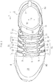
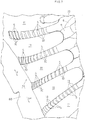
- the shoe shown in FIG. 1 is a shoe for sports or running, for example, and includes an upper 3 secured to a sole 8 shown in FIG. 2 .
- the upper 3 includes a flexible member 33, a reinforcement member 34 and a shoelace (fastening member) 6 .
- the sole 8 is placed under the upper 3 and is to be in contact with the road surface.
- the flexible member 33 wraps the medial side surface, the lateral side surface, the toe and the heel of the foot, and is formed in the shape of a sock, for example.
- the reinforcement member 34 and the shoelace 6 are for fitting the flexible member 33 to the instep.
- the end portions of the shoelace 6 are not shown in FIG. 1 to FIG. 3 , the end portions are firmly tied together after the foot is inserted in the flexible member 33. As the end portions of the shoelace 6 are tied together, the flexible member 33 fits to the foot.
- the flexible member 33 includes a top line (wearing opening) 7 allowing the foot to be inserted to wear the shoe.
- the leg protrudes upward through the top line 7 when the shoe is worn, and the shoelace 6 is placed in an area anterior to the top line 7 .
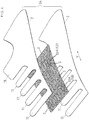
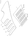
- the reinforcement member 34 includes a mesh member 1 and a pair of panel members 2 .
- the mesh member 1 uses such a structure and material that it is less stretchable in the longitudinal direction Y than the panel members 2 .
- the panel members 2 preferably have a greater flexural rigidity than the mesh member 1 .
- the material of the panel members 2 may be any of various materials, such as a resin part, an artificial leather, a TPU or a rubber.
- flexural rigidity of the mesh member 1 and that of the panel members 2 may be similar to each other.
- the panel members 2 are comb-shaped, for example, including a plurality of panels 11 to be described later.
- the mesh member 1 includes a large number of string portions 10 to be described later.
- the mesh member 1 of FIG. 4 is formed by a woven fabric or a knit fabric, for example, and is more preferably formed by a woven fabric, defining a larger number of elongate slit-shaped through holes S arranged in a plurality of columns and a plurality of rows.
- the panel members 2 are layered on the front side and the back side of the mesh member 1 , while the through holes S arranged in the plurality of columns and the plurality of rows are open and the areas of the mesh member 1 between through holes S that are adjacent to each other (hereinafter referred to as exposed portions 10A ) are exposed. That is, the panel members 2 are layered together with the mesh member 1 sandwiched therebetween.
- the mesh member 1 may be formed by a thin resin film (FRP) containing a reinforcement fiber extending in the longitudinal direction Y .
- FRP thin resin film
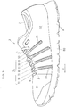
- the reinforcement member 34 of FIG. 1 to FIG. 3 is joined with the upper surface of a midsole 80 by bonding and/or welding, for example, and includes a medial side portion 31 covering the medial side surface of the instep and a lateral side portion 32 covering the lateral side surface of the instep.
- the medial side portion 31 and the lateral side portion 32 of the reinforcement member 34 include a plurality of panels 11 and a large number of string portions 10 .
- the panels 11 and the string portions 10 will be described in detail. Note that the medial side portion 31 and the lateral side portion 32 are similar in structure.
- the panels 11 are separated from each other in the longitudinal direction Y of the foot, covering at least a portion of the side surface of the foot, wherein the panels 11 are pulled by the shoelace (an example of the fastening member) 6 toward a center portion 36 between the medial side and the lateral side of the foot. That is, for example, loops R are sewn to the upper end portions of the panels 11 of FIG. 1 , with the shoelace 6 passed through the loops R .
- the panels 11 of FIG. 2 and FIG. 3 covering the side surface of the instep extend in the transverse direction X of the foot ( FIG. 1 ) and/or in the up-down direction (including an inclined up-down direction). Note that the string portions 10 cover the side surface of the instep.
- instep means a part that is posterior to the metatarsal phalangeal joint MP of FIG. 10 and anterior to the anterior end Be of the talus, and that covers the upper surface and the side surface of the foot.
- the panels 11 may or may not cover the toe anterior to the metatarsal phalangeal joint MP and the heel portion posterior to the anterior end Be of the talus as do the posterior panels 11 of FIG. 2 .
- the panels 11 covering the side surface of the instep are each formed in a rectangular band shape (strip shape) extending in a diagonal posterior direction or in the up-down direction toward the midsole 80 from the upper end portion thereof with which the loop R is joined.
- the panels 11 are separated from each other in the longitudinal direction Y or in a diagonal longitudinal direction, with a large number of string portions 10 placed between panels 11 that are adjacent to each other.
- the slit-shaped through holes S of the mesh member 1 of FIG. 4 extend generally in parallel to each other in a diagonal longitudinal direction Y .
- the through holes S are regularly arranged in the diagonal longitudinal direction Y and in the transverse direction.
- each exposed area 10A forms a string portion 10 of FIG. 3 extending in the longitudinal direction Y between those through holes S that are separated from, and adjacent to, each other in the circumferential direction of the foot.
- the string portions 10 are non-elongatable (non-stretchable) in the longitudinal direction Y.
- Such non-stretchable string portions 10 may be formed by the woven fabric of the mesh member 1 of FIG. 4 including a plurality of strands of a non-stretchable fiber that are long in the longitudinal direction Y.
- the string portions 10 may be stretchable by including another fiber stretchable in the longitudinal direction Y .
- each string portion 10 is formed in a string-like form placed between a pair of panels 11 adjacent to each other the longitudinal direction Y and extending in the longitudinal direction Y .
- the width W in the up-down direction of each string portion 10 of FIG. 6 is set to be about 2 mm to about 5 mm, for example, and each string portion 10 has a planar shape with a small area and is formed in a linear shape.
- the string portions 10 are set so that the string portions 10 are freely displaceable and/or deformable in the transverse direction X of the foot ( FIG. 1 ) and/or in the up-down direction.
- the width W in the up-down direction of the string portion 10 means the distance between the upper edge and the lower edge of one string portion 10.
- the width W means the distance between a pair of intersections O and O at which a virtual line intersects with the two edges of one string portion 10 , wherein the virtual line extends across the string portion 10 in the up-down direction or in a diagonal up-down direction (extends perpendicular to the direction in which the string portion 10 extends). Note that these distances should be considered to be those along the curve of the surface of the foot.
- the plurality of string portions 10 are arranged generally at a constant pitch P in the up-down direction.
- the ratio W/P of the width W with respect to the pitch P of the string portions 10 in the up-down direction is set to be about 60% to about 80%, for example.
- the pitch P of the string portions 10 means the distance between the center line CL of one string portion 10 and the center line CL of another adjacent string portion 10 , with the center line extending in the extending direction of the string portion 10.
- the length L of the string portions 10 i.e., the length L of the string portions 10 between a pair of panels 11 that are adjacent to each other, is set to be about 4 to about 10 mm, for example.
- the preferable thickness of the string portions 10 i.e., the thickness of the mesh member 1 of FIG. 4 , will commonly be about 0.5 to about 1.5 mm.
- the flexible member 33 of FIG. 5 is formed by, for example, a foamed resin, a knit fabric, a meshed member or a combination thereof, and is more stretchable in the longitudinal direction Y than the string portions 10 and the panels 11. As shown in FIG. 1 to FIG. 3 , the reinforcement member 34 including the panels 11 and the string portions 10 are placed on the outer surface of the flexible member 33.
- the reinforcement member 34 including the panels 11 and the string portions 10 is placed along the outer surface of the flexible member 33 on the medial side and on the lateral side of the instep.
- the majority of the panels 11 and the string portions 10 are set to be unattached to the outer surface of the flexible member 33.
- the string portions 10 are freely displaceable and/or deformable in the transverse direction X of the foot and/or in the up-down direction. Note that it is preferred that at least an upper-half area of each panel 11 is in contact with, while being unattached to, the outer surface of the flexible member 33 on the medial side and on the lateral side of the instep.
- the lower edge of the reinforcement member 34 is attached (secured) to the midsole 80 as described above.
- the reinforcement member 34 is attached (sewn) to the flexible member 33 at the rear end of the upper 3.
- attachment may be replaced by the word “secured”, and it conceptually means that objects are joined together in such a manner that they cannot be removed easily. Specifically, “attached” means that objects are joined together by means of bonding, welding or sewing, or by a combination of two or more of these means.
- unattached state means a free state in which the panel 11 or the reinforcement member 34 is not attached to the flexible member 33.
- the panel 11 or the reinforcement member 34 in the unattached state is not bound by the flexible member 33 and will be allowed to undergo displacement or deformation such as twist or rotation about the position of attachment as the center.
- areas of the flexible member 33 where the string portions 10 or the panels 11 are not attached will be allowed to undergo stretching/shrinking deformation in response to deformation of the foot or the upper.
- At least one of the plurality of panels 11 or at least a part of the plurality of non-stretchable string portions 10 covers at least a portion of the side surface of the ball O1 of the big toe on the medial side of the foot shown in FIG. 10 .
- at least one of the plurality of panels 11 or at least a part of the plurality of non-stretchable string portions 10 covers at least a portion of the side surface of the ball O5 of the little toe on the lateral side of the foot shown in FIG. 10 .
- “dorsiflexion of the foot” in the present embodiment means dorsiflexion of a joint within the foot (e.g., the metatarsal phalangeal joint, the interphalangeal joint, etc.).
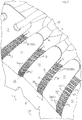
- the string portions 10 of FIG. 7 when dorsiflexed, exhibit a deformation as if it were shrunk in the direction along the upper surface of the instep. This deformation may be realized by the string portions 10 actually shrinking, as well as by deformation of the surface of the planar string portions 10 into a curved surface.
- each panel 11 displaces so that the distance between panels 11 that are adjacent to each other shortens upon dorsiflexion.
- the lower end of the panel member 2 is attached to the midsole 80 . Therefore, each panel 11 inclines in the anterior direction YF about the position of attachment as the center.
- the panels 11 and the string portions 10 displace and deform at the same time.
- the reinforcement member 34 may include a single mesh member 1 layered with a single panel member 2 .
- the string portions 10 are shown in solid black.
- a large number of string members 10B may be sandwiched between the panels 11 and the flexible member 33 , thereby forming the string portions 10 between the panels 11 and 11 .
- the string portions 10 are set to be unattached to the flexible member 33 .
- each panel may be secured to the flexible member.
- the flexural rigidity of the panel member may be smaller than or similar to that of the mesh member.
- the sole placed under the upper may only include a so-called "outsole".
- the panels and the string portions may be provided only in one of the medial side portion and the lateral side portion.
- a tongue may be provided in the center portion of the upper.
- the shoelace passing holes may be eyelets instead of loops.
- a belt may be employed as the fastening member instead of, or in addition to, a shoelace.
- the present invention is applicable to shoes for court sports and running shoes, and also to shoes of various other applications such as walking.
Landscapes
- Health & Medical Sciences (AREA)
- General Health & Medical Sciences (AREA)
- Chemical & Material Sciences (AREA)
- Engineering & Computer Science (AREA)
- Materials Engineering (AREA)
- Epidemiology (AREA)
- Public Health (AREA)
- Physical Education & Sports Medicine (AREA)
- Footwear And Its Accessory, Manufacturing Method And Apparatuses (AREA)
Applications Claiming Priority (1)
| Application Number | Priority Date | Filing Date | Title |
|---|---|---|---|
| PCT/JP2014/064275 WO2015181928A1 (ja) | 2014-05-29 | 2014-05-29 | 靴のアッパー |
Publications (3)
| Publication Number | Publication Date |
|---|---|
| EP3150077A1 true EP3150077A1 (de) | 2017-04-05 |
| EP3150077A4 EP3150077A4 (de) | 2017-08-09 |
| EP3150077B1 EP3150077B1 (de) | 2018-07-04 |
Family
ID=54698307
Family Applications (1)
| Application Number | Title | Priority Date | Filing Date |
|---|---|---|---|
| EP14893246.0A Active EP3150077B1 (de) | 2014-05-29 | 2014-05-29 | Schuhoberteil |
Country Status (4)
| Country | Link |
|---|---|
| US (1) | US10165830B2 (de) |
| EP (1) | EP3150077B1 (de) |
| JP (1) | JP5909032B1 (de) |
| WO (1) | WO2015181928A1 (de) |
Families Citing this family (42)
| Publication number | Priority date | Publication date | Assignee | Title |
|---|---|---|---|---|
| CN103381003B (zh) | 2004-10-29 | 2016-05-25 | 博技术有限公司 | 基于卷轴的闭合系统 |
| US8468657B2 (en) | 2008-11-21 | 2013-06-25 | Boa Technology, Inc. | Reel based lacing system |
| US9375053B2 (en) | 2012-03-15 | 2016-06-28 | Boa Technology, Inc. | Tightening mechanisms and applications including the same |
| US10070695B2 (en) | 2010-04-30 | 2018-09-11 | Boa Technology Inc. | Tightening mechanisms and applications including the same |
| US9101181B2 (en) | 2011-10-13 | 2015-08-11 | Boa Technology Inc. | Reel-based lacing system |
| US9516923B2 (en) | 2012-11-02 | 2016-12-13 | Boa Technology Inc. | Coupling members for closure devices and systems |
| US9737115B2 (en) | 2012-11-06 | 2017-08-22 | Boa Technology Inc. | Devices and methods for adjusting the fit of footwear |
| EP2948014B1 (de) | 2013-01-28 | 2019-06-26 | Boa Technology Inc. | Riemenfixieranordnung und system |
| US10702409B2 (en) | 2013-02-05 | 2020-07-07 | Boa Technology Inc. | Closure devices for medical devices and methods |
| WO2014138297A1 (en) | 2013-03-05 | 2014-09-12 | Boa Technology Inc. | Systems, methods, and devices for automatic closure of medical devices |
| US10251451B2 (en) | 2013-03-05 | 2019-04-09 | Boa Technology Inc. | Closure devices including incremental release mechanisms and methods therefor |
| WO2014165541A2 (en) | 2013-04-01 | 2014-10-09 | Boa Technology Inc. | Methods and devices for retrofitting footwear to include a reel based closure system |
| US10076160B2 (en) | 2013-06-05 | 2018-09-18 | Boa Technology Inc. | Integrated closure device components and methods |
| JP6778103B2 (ja) | 2013-06-05 | 2020-10-28 | ボア テクノロジー,インコーポレイテッド | 一体化されたクロージャー装置部品および方法 |
| DE112014003135B4 (de) | 2013-07-02 | 2020-12-24 | Boa Technology Inc. | Rolle zur verwendung mit einem verschnürungssystem zum festziehen eines gegenstandes sowie vorrichtungen hierzu und verfahren zum zusammenbauen einer vorrichtung zum festziehen eines gegenstandes |
| EP3019043B1 (de) | 2013-07-10 | 2019-09-18 | Boa Technology Inc. | Verschlussvorrichtungen mit inkrementellen lösemechanismen und verfahren dafür |
| US9700101B2 (en) | 2013-09-05 | 2017-07-11 | Boa Technology Inc. | Guides and components for closure systems and methods therefor |
| KR20230084599A (ko) | 2013-09-13 | 2023-06-13 | 보아 테크놀러지, 인크. | 릴 기반 폐쇄 장치 및 그에 따른 방법 |
| JP6526691B2 (ja) | 2013-11-18 | 2019-06-05 | ボア テクノロジー,インコーポレイテッド | 補装具および整形用支持具を自動的に閉じる方法および装置 |
| USD835976S1 (en) | 2014-01-16 | 2018-12-18 | Boa Technology Inc. | Coupling member |
| US20160058127A1 (en) | 2014-08-28 | 2016-03-03 | Boa Technology Inc. | Devices and methods for enhancing the fit of boots and other footwear |
| WO2016057697A1 (en) | 2014-10-07 | 2016-04-14 | Boa Technology Inc. | A tension adjustment mechanism and a method for adjusting the fit of a shoe |
| USD835898S1 (en) | 2015-01-16 | 2018-12-18 | Boa Technology Inc. | Footwear lace tightening reel stabilizer |
| CN208463051U (zh) * | 2015-05-08 | 2019-02-05 | 安德玛有限公司 | 鞋履制品 |
| US10004297B2 (en) | 2015-10-15 | 2018-06-26 | Boa Technology Inc. | Lacing configurations for footwear |
| JP6581941B2 (ja) * | 2016-04-26 | 2019-09-25 | 美津濃株式会社 | シューズ用アッパーおよびそれを用いたシューズ |
| KR102391910B1 (ko) | 2016-08-02 | 2022-04-28 | 보아 테크놀러지, 인크. | 신발끈 결속 시스템의 인장 부재 가이드 |
| KR20230020012A (ko) | 2016-12-09 | 2023-02-09 | 보아 테크놀러지, 인크. | 릴 기반의 폐쇄 시스템 |
| US10543630B2 (en) | 2017-02-27 | 2020-01-28 | Boa Technology Inc. | Reel based closure system employing a friction based tension mechanism |
| CN110392535B (zh) * | 2017-03-06 | 2022-07-08 | 富尔斯特集团有限公司 | 具有带边缘的编织鞋面的鞋类制品 |
| JP6826653B2 (ja) | 2017-03-20 | 2021-02-03 | 株式会社アシックス | 靴のアッパー |
| US11357279B2 (en) | 2017-05-09 | 2022-06-14 | Boa Technology Inc. | Closure components for a helmet layer and methods for installing same |
| CN110891448B (zh) * | 2017-05-31 | 2022-09-23 | 耐克创新有限合伙公司 | 用于鞋类物品的针织部件 |
| EP3629817B1 (de) * | 2017-05-31 | 2024-04-17 | NIKE Innovate C.V. | Gestrickte komponente für einen schuhartikel |
| US10772384B2 (en) | 2017-07-18 | 2020-09-15 | Boa Technology Inc. | System and methods for minimizing dynamic lace movement |
| US10834998B2 (en) * | 2018-04-13 | 2020-11-17 | Wolverine Outdoors, Inc. | Footwear including a holding cage |
| JP6582109B2 (ja) * | 2018-10-26 | 2019-09-25 | 美津濃株式会社 | シューズ用アッパーおよびそれを用いたシューズ |
| EP3955765B1 (de) * | 2019-04-17 | 2023-08-16 | NIKE Innovate C.V. | Schuhoberteil mit verzweigten vorderfussbändern |
| JP7454267B2 (ja) | 2019-05-01 | 2024-03-22 | ボア テクノロジー,インコーポレイテッド | リール式クロージャーシステム |
| US11129445B1 (en) * | 2020-03-26 | 2021-09-28 | Nike, Inc. | Lacing systems and methods of manufacturing the same |
| USD950227S1 (en) * | 2020-10-22 | 2022-05-03 | Nike, Inc. | Shoe |
| CN116801761A (zh) * | 2021-01-21 | 2023-09-22 | 株式会社爱世克私 | 鞋面及具备该鞋面的鞋子 |
Family Cites Families (31)
| Publication number | Priority date | Publication date | Assignee | Title |
|---|---|---|---|---|
| US2147197A (en) * | 1936-11-25 | 1939-02-14 | Hood Rubber Co Inc | Article of footwear |
| US4817303A (en) * | 1987-07-17 | 1989-04-04 | Avia Group International, Inc. | Athletic shoe having a dual side lacing system |
| US5377430A (en) * | 1993-09-17 | 1995-01-03 | Nike, Inc. | Shoe with elastic closure system |
| JP2004313443A (ja) | 2003-04-16 | 2004-11-11 | Asics Corp | 靴形状選択方法、靴形状選択システムおよび靴先形状選択方法 |
| WO2004093587A1 (ja) | 2003-04-24 | 2004-11-04 | Asics Corporation | アッパーのフィット性を改良した運動靴 |
| USD518283S1 (en) | 2003-07-18 | 2006-04-04 | Asics Corporation | Shoe upper |
| USD528761S1 (en) | 2003-07-18 | 2006-09-26 | Asics Corporation | Portion of a shoe upper |
| US6990755B2 (en) | 2003-10-09 | 2006-01-31 | Nike, Inc. | Article of footwear with a stretchable upper and an articulated sole structure |
| US7293371B2 (en) * | 2004-09-22 | 2007-11-13 | Nike, Inc. | Woven shoe with integral lace loops |
| US7836608B2 (en) * | 2004-12-06 | 2010-11-23 | Nike, Inc. | Article of footwear formed of multiple links |
| US20070199210A1 (en) * | 2006-02-24 | 2007-08-30 | The Timberland Company | Compression molded footwear and methods of manufacture |
| US7870681B2 (en) * | 2006-05-25 | 2011-01-18 | Nike, Inc. | Article of footwear having an upper with thread structural elements |
| US8312645B2 (en) | 2006-05-25 | 2012-11-20 | Nike, Inc. | Material elements incorporating tensile strands |
| US7546698B2 (en) | 2006-05-25 | 2009-06-16 | Nike, Inc. | Article of footwear having an upper with thread structural elements |
| US7574818B2 (en) * | 2006-05-25 | 2009-08-18 | Nike, Inc. | Article of footwear having an upper with thread structural elements |
| DE202006009950U1 (de) | 2006-06-26 | 2007-11-08 | Puma Aktiengesellschaft Rudolf Dassler Sport | Schuh, insbesondere Sportschuh |
| EP2078468B1 (de) | 2006-10-19 | 2017-02-08 | ASICS Corporation | Sportschuh mit obermaterialabschnitt mit verbesserter eignung |
| US8225530B2 (en) | 2006-11-10 | 2012-07-24 | Nike, Inc. | Article of footwear having a flat knit upper construction or other upper construction |
| US8008599B2 (en) * | 2007-07-09 | 2011-08-30 | Nike, Inc. | Method for manufacturing layered elements with incisions |
| US8037621B2 (en) * | 2007-09-13 | 2011-10-18 | Nike, Inc. | Article of footwear including a woven strap system |
| DE102009028627B4 (de) * | 2009-08-18 | 2019-12-19 | Adidas Ag | Sportschuh |
| US8266827B2 (en) * | 2009-08-24 | 2012-09-18 | Nike, Inc. | Article of footwear incorporating tensile strands and securing strands |
| WO2011129017A1 (ja) | 2010-04-16 | 2011-10-20 | 株式会社アシックス | 靴のアッパーの前足部の構造 |
| US8578632B2 (en) * | 2010-07-19 | 2013-11-12 | Nike, Inc. | Decoupled foot stabilizer system |
| US9282787B2 (en) * | 2011-06-10 | 2016-03-15 | Crocs, Inc. | Molded footwear with woven appearance and ventilation features |
| US9038288B2 (en) * | 2011-09-26 | 2015-05-26 | Nike, Inc. | Athletic footwear with ball control portions |
| US20150289589A1 (en) | 2012-10-24 | 2015-10-15 | Asics Corporation | Upper Provided With Sponge Member in Heel Part |
| JP5442170B1 (ja) * | 2013-01-24 | 2014-03-12 | 株式会社アシックス | 靴およびその製造方法 |
| US9826799B2 (en) * | 2013-03-14 | 2017-11-28 | Nike, Inc. | Uppers and articles incorporating same |
| US9301567B2 (en) * | 2014-08-29 | 2016-04-05 | Nike, Inc. | Article of footwear incorporating a knitted component with monofilament areas |
| DE102014220087B4 (de) * | 2014-10-02 | 2016-05-12 | Adidas Ag | Flachgestricktes Schuhoberteil für Sportschuhe |
-
2014
- 2014-05-29 EP EP14893246.0A patent/EP3150077B1/de active Active
- 2014-05-29 WO PCT/JP2014/064275 patent/WO2015181928A1/ja active Application Filing
- 2014-05-29 JP JP2015556885A patent/JP5909032B1/ja active Active
- 2014-05-29 US US15/313,371 patent/US10165830B2/en active Active
Also Published As
| Publication number | Publication date |
|---|---|
| US20170215523A1 (en) | 2017-08-03 |
| US10165830B2 (en) | 2019-01-01 |
| JP5909032B1 (ja) | 2016-04-26 |
| WO2015181928A1 (ja) | 2015-12-03 |
| EP3150077B1 (de) | 2018-07-04 |
| EP3150077A4 (de) | 2017-08-09 |
| JPWO2015181928A1 (ja) | 2017-04-20 |
Similar Documents
| Publication | Publication Date | Title |
|---|---|---|
| EP3150077B1 (de) | Schuhoberteil | |
| US8713821B2 (en) | Athletic shoes having an upper whose fitting property is improved | |
| EP2559352B1 (de) | Struktur für den vorderfussteil eines schuhobermaterials | |
| US20210127786A1 (en) | Article of Footwear with Multiple Durometer Outsole | |
| JP6473201B1 (ja) | シューズ | |
| US20110252666A1 (en) | Footwear with expandable entry and exit feature | |
| CN104379014A (zh) | 配置为允许相对的脚跟/前脚运动的鞋底结构 | |
| EP3130247B1 (de) | Schuhobermaterial | |
| AU2011275838B2 (en) | Shoe | |
| US20170251762A1 (en) | Footwear Upper With Ribbed Panels | |
| CN114080166B (zh) | 具有自适应鞋面材料的跑鞋 | |
| JP4351199B2 (ja) | アッパーのフィット性を改良した運動靴 | |
| JP2005329270A6 (ja) | アッパーのフィット性を改良した運動靴 | |
| US20190069640A1 (en) | Shoes | |
| EP3954244A1 (de) | Schuh | |
| US10212989B2 (en) | Shoe having upper and sole | |
| US20120255200A1 (en) | Upper Structure for a Shoe |
Legal Events
| Date | Code | Title | Description |
|---|---|---|---|
| STAA | Information on the status of an ep patent application or granted ep patent |
Free format text: STATUS: THE INTERNATIONAL PUBLICATION HAS BEEN MADE |
|
| PUAI | Public reference made under article 153(3) epc to a published international application that has entered the european phase |
Free format text: ORIGINAL CODE: 0009012 |
|
| STAA | Information on the status of an ep patent application or granted ep patent |
Free format text: STATUS: REQUEST FOR EXAMINATION WAS MADE |
|
| 17P | Request for examination filed |
Effective date: 20161130 |
|
| AK | Designated contracting states |
Kind code of ref document: A1 Designated state(s): AL AT BE BG CH CY CZ DE DK EE ES FI FR GB GR HR HU IE IS IT LI LT LU LV MC MK MT NL NO PL PT RO RS SE SI SK SM TR |
|
| AX | Request for extension of the european patent |
Extension state: BA ME |
|
| A4 | Supplementary search report drawn up and despatched |
Effective date: 20170710 |
|
| RIC1 | Information provided on ipc code assigned before grant |
Ipc: A43B 23/02 20060101AFI20170704BHEP Ipc: A43C 1/04 20060101ALI20170704BHEP Ipc: A43B 1/04 20060101ALI20170704BHEP |
|
| DAX | Request for extension of the european patent (deleted) | ||
| REG | Reference to a national code |
Ref country code: DE Ref legal event code: R079 Ref document number: 602014028121 Country of ref document: DE Free format text: PREVIOUS MAIN CLASS: A43B0023020000 Ipc: A43B0005060000 |
|
| GRAP | Despatch of communication of intention to grant a patent |
Free format text: ORIGINAL CODE: EPIDOSNIGR1 |
|
| STAA | Information on the status of an ep patent application or granted ep patent |
Free format text: STATUS: GRANT OF PATENT IS INTENDED |
|
| RIC1 | Information provided on ipc code assigned before grant |
Ipc: A43B 1/04 20060101ALI20180126BHEP Ipc: A43B 5/06 20060101AFI20180126BHEP Ipc: A43C 1/04 20060101ALI20180126BHEP Ipc: A43B 23/02 20060101ALI20180126BHEP |
|
| INTG | Intention to grant announced |
Effective date: 20180214 |
|
| RIN1 | Information on inventor provided before grant (corrected) |
Inventor name: FUJITA, YOSHINORI Inventor name: FUJITA, HISANORI Inventor name: TAKASHIMA, SHINGO Inventor name: NISHIWAKI, TSUYOSHI |
|
| GRAJ | Information related to disapproval of communication of intention to grant by the applicant or resumption of examination proceedings by the epo deleted |
Free format text: ORIGINAL CODE: EPIDOSDIGR1 |
|
| STAA | Information on the status of an ep patent application or granted ep patent |
Free format text: STATUS: REQUEST FOR EXAMINATION WAS MADE |
|
| GRAS | Grant fee paid |
Free format text: ORIGINAL CODE: EPIDOSNIGR3 |
|
| STAA | Information on the status of an ep patent application or granted ep patent |
Free format text: STATUS: GRANT OF PATENT IS INTENDED |
|
| GRAP | Despatch of communication of intention to grant a patent |
Free format text: ORIGINAL CODE: EPIDOSNIGR1 |
|
| INTC | Intention to grant announced (deleted) | ||
| GRAA | (expected) grant |
Free format text: ORIGINAL CODE: 0009210 |
|
| STAA | Information on the status of an ep patent application or granted ep patent |
Free format text: STATUS: THE PATENT HAS BEEN GRANTED |
|
| INTG | Intention to grant announced |
Effective date: 20180514 |
|
| AK | Designated contracting states |
Kind code of ref document: B1 Designated state(s): AL AT BE BG CH CY CZ DE DK EE ES FI FR GB GR HR HU IE IS IT LI LT LU LV MC MK MT NL NO PL PT RO RS SE SI SK SM TR |
|
| REG | Reference to a national code |
Ref country code: GB Ref legal event code: FG4D |
|
| REG | Reference to a national code |
Ref country code: CH Ref legal event code: EP |
|
| REG | Reference to a national code |
Ref country code: AT Ref legal event code: REF Ref document number: 1013571 Country of ref document: AT Kind code of ref document: T Effective date: 20180715 |
|
| REG | Reference to a national code |
Ref country code: IE Ref legal event code: FG4D |
|
| REG | Reference to a national code |
Ref country code: DE Ref legal event code: R096 Ref document number: 602014028121 Country of ref document: DE |
|
| REG | Reference to a national code |
Ref country code: NL Ref legal event code: MP Effective date: 20180704 |
|
| REG | Reference to a national code |
Ref country code: LT Ref legal event code: MG4D |
|
| REG | Reference to a national code |
Ref country code: AT Ref legal event code: MK05 Ref document number: 1013571 Country of ref document: AT Kind code of ref document: T Effective date: 20180704 |
|
| PG25 | Lapsed in a contracting state [announced via postgrant information from national office to epo] |
Ref country code: NL Free format text: LAPSE BECAUSE OF FAILURE TO SUBMIT A TRANSLATION OF THE DESCRIPTION OR TO PAY THE FEE WITHIN THE PRESCRIBED TIME-LIMIT Effective date: 20180704 |
|
| PG25 | Lapsed in a contracting state [announced via postgrant information from national office to epo] |
Ref country code: CZ Free format text: LAPSE BECAUSE OF FAILURE TO SUBMIT A TRANSLATION OF THE DESCRIPTION OR TO PAY THE FEE WITHIN THE PRESCRIBED TIME-LIMIT Effective date: 20180704 Ref country code: FI Free format text: LAPSE BECAUSE OF FAILURE TO SUBMIT A TRANSLATION OF THE DESCRIPTION OR TO PAY THE FEE WITHIN THE PRESCRIBED TIME-LIMIT Effective date: 20180704 Ref country code: PL Free format text: LAPSE BECAUSE OF FAILURE TO SUBMIT A TRANSLATION OF THE DESCRIPTION OR TO PAY THE FEE WITHIN THE PRESCRIBED TIME-LIMIT Effective date: 20180704 Ref country code: NO Free format text: LAPSE BECAUSE OF FAILURE TO SUBMIT A TRANSLATION OF THE DESCRIPTION OR TO PAY THE FEE WITHIN THE PRESCRIBED TIME-LIMIT Effective date: 20181004 Ref country code: SE Free format text: LAPSE BECAUSE OF FAILURE TO SUBMIT A TRANSLATION OF THE DESCRIPTION OR TO PAY THE FEE WITHIN THE PRESCRIBED TIME-LIMIT Effective date: 20180704 Ref country code: BG Free format text: LAPSE BECAUSE OF FAILURE TO SUBMIT A TRANSLATION OF THE DESCRIPTION OR TO PAY THE FEE WITHIN THE PRESCRIBED TIME-LIMIT Effective date: 20181004 Ref country code: GR Free format text: LAPSE BECAUSE OF FAILURE TO SUBMIT A TRANSLATION OF THE DESCRIPTION OR TO PAY THE FEE WITHIN THE PRESCRIBED TIME-LIMIT Effective date: 20181005 Ref country code: RS Free format text: LAPSE BECAUSE OF FAILURE TO SUBMIT A TRANSLATION OF THE DESCRIPTION OR TO PAY THE FEE WITHIN THE PRESCRIBED TIME-LIMIT Effective date: 20180704 Ref country code: LT Free format text: LAPSE BECAUSE OF FAILURE TO SUBMIT A TRANSLATION OF THE DESCRIPTION OR TO PAY THE FEE WITHIN THE PRESCRIBED TIME-LIMIT Effective date: 20180704 Ref country code: IS Free format text: LAPSE BECAUSE OF FAILURE TO SUBMIT A TRANSLATION OF THE DESCRIPTION OR TO PAY THE FEE WITHIN THE PRESCRIBED TIME-LIMIT Effective date: 20181104 Ref country code: AT Free format text: LAPSE BECAUSE OF FAILURE TO SUBMIT A TRANSLATION OF THE DESCRIPTION OR TO PAY THE FEE WITHIN THE PRESCRIBED TIME-LIMIT Effective date: 20180704 |
|
| PG25 | Lapsed in a contracting state [announced via postgrant information from national office to epo] |
Ref country code: HR Free format text: LAPSE BECAUSE OF FAILURE TO SUBMIT A TRANSLATION OF THE DESCRIPTION OR TO PAY THE FEE WITHIN THE PRESCRIBED TIME-LIMIT Effective date: 20180704 Ref country code: ES Free format text: LAPSE BECAUSE OF FAILURE TO SUBMIT A TRANSLATION OF THE DESCRIPTION OR TO PAY THE FEE WITHIN THE PRESCRIBED TIME-LIMIT Effective date: 20180704 Ref country code: AL Free format text: LAPSE BECAUSE OF FAILURE TO SUBMIT A TRANSLATION OF THE DESCRIPTION OR TO PAY THE FEE WITHIN THE PRESCRIBED TIME-LIMIT Effective date: 20180704 Ref country code: LV Free format text: LAPSE BECAUSE OF FAILURE TO SUBMIT A TRANSLATION OF THE DESCRIPTION OR TO PAY THE FEE WITHIN THE PRESCRIBED TIME-LIMIT Effective date: 20180704 |
|
| REG | Reference to a national code |
Ref country code: DE Ref legal event code: R097 Ref document number: 602014028121 Country of ref document: DE |
|
| PG25 | Lapsed in a contracting state [announced via postgrant information from national office to epo] |
Ref country code: RO Free format text: LAPSE BECAUSE OF FAILURE TO SUBMIT A TRANSLATION OF THE DESCRIPTION OR TO PAY THE FEE WITHIN THE PRESCRIBED TIME-LIMIT Effective date: 20180704 Ref country code: EE Free format text: LAPSE BECAUSE OF FAILURE TO SUBMIT A TRANSLATION OF THE DESCRIPTION OR TO PAY THE FEE WITHIN THE PRESCRIBED TIME-LIMIT Effective date: 20180704 Ref country code: IT Free format text: LAPSE BECAUSE OF FAILURE TO SUBMIT A TRANSLATION OF THE DESCRIPTION OR TO PAY THE FEE WITHIN THE PRESCRIBED TIME-LIMIT Effective date: 20180704 |
|
| PLBE | No opposition filed within time limit |
Free format text: ORIGINAL CODE: 0009261 |
|
| STAA | Information on the status of an ep patent application or granted ep patent |
Free format text: STATUS: NO OPPOSITION FILED WITHIN TIME LIMIT |
|
| PG25 | Lapsed in a contracting state [announced via postgrant information from national office to epo] |
Ref country code: DK Free format text: LAPSE BECAUSE OF FAILURE TO SUBMIT A TRANSLATION OF THE DESCRIPTION OR TO PAY THE FEE WITHIN THE PRESCRIBED TIME-LIMIT Effective date: 20180704 Ref country code: SK Free format text: LAPSE BECAUSE OF FAILURE TO SUBMIT A TRANSLATION OF THE DESCRIPTION OR TO PAY THE FEE WITHIN THE PRESCRIBED TIME-LIMIT Effective date: 20180704 Ref country code: SM Free format text: LAPSE BECAUSE OF FAILURE TO SUBMIT A TRANSLATION OF THE DESCRIPTION OR TO PAY THE FEE WITHIN THE PRESCRIBED TIME-LIMIT Effective date: 20180704 |
|
| 26N | No opposition filed |
Effective date: 20190405 |
|
| PG25 | Lapsed in a contracting state [announced via postgrant information from national office to epo] |
Ref country code: SI Free format text: LAPSE BECAUSE OF FAILURE TO SUBMIT A TRANSLATION OF THE DESCRIPTION OR TO PAY THE FEE WITHIN THE PRESCRIBED TIME-LIMIT Effective date: 20180704 |
|
| REG | Reference to a national code |
Ref country code: CH Ref legal event code: PL |
|
| PG25 | Lapsed in a contracting state [announced via postgrant information from national office to epo] |
Ref country code: CH Free format text: LAPSE BECAUSE OF NON-PAYMENT OF DUE FEES Effective date: 20190531 Ref country code: LI Free format text: LAPSE BECAUSE OF NON-PAYMENT OF DUE FEES Effective date: 20190531 Ref country code: MC Free format text: LAPSE BECAUSE OF FAILURE TO SUBMIT A TRANSLATION OF THE DESCRIPTION OR TO PAY THE FEE WITHIN THE PRESCRIBED TIME-LIMIT Effective date: 20180704 |
|
| REG | Reference to a national code |
Ref country code: BE Ref legal event code: MM Effective date: 20190531 |
|
| PG25 | Lapsed in a contracting state [announced via postgrant information from national office to epo] |
Ref country code: LU Free format text: LAPSE BECAUSE OF NON-PAYMENT OF DUE FEES Effective date: 20190529 |
|
| PG25 | Lapsed in a contracting state [announced via postgrant information from national office to epo] |
Ref country code: TR Free format text: LAPSE BECAUSE OF FAILURE TO SUBMIT A TRANSLATION OF THE DESCRIPTION OR TO PAY THE FEE WITHIN THE PRESCRIBED TIME-LIMIT Effective date: 20180704 |
|
| PG25 | Lapsed in a contracting state [announced via postgrant information from national office to epo] |
Ref country code: IE Free format text: LAPSE BECAUSE OF NON-PAYMENT OF DUE FEES Effective date: 20190529 |
|
| PG25 | Lapsed in a contracting state [announced via postgrant information from national office to epo] |
Ref country code: BE Free format text: LAPSE BECAUSE OF NON-PAYMENT OF DUE FEES Effective date: 20190531 |
|
| PG25 | Lapsed in a contracting state [announced via postgrant information from national office to epo] |
Ref country code: PT Free format text: LAPSE BECAUSE OF FAILURE TO SUBMIT A TRANSLATION OF THE DESCRIPTION OR TO PAY THE FEE WITHIN THE PRESCRIBED TIME-LIMIT Effective date: 20181104 Ref country code: FR Free format text: LAPSE BECAUSE OF NON-PAYMENT OF DUE FEES Effective date: 20190531 |
|
| PG25 | Lapsed in a contracting state [announced via postgrant information from national office to epo] |
Ref country code: CY Free format text: LAPSE BECAUSE OF FAILURE TO SUBMIT A TRANSLATION OF THE DESCRIPTION OR TO PAY THE FEE WITHIN THE PRESCRIBED TIME-LIMIT Effective date: 20180704 |
|
| PG25 | Lapsed in a contracting state [announced via postgrant information from national office to epo] |
Ref country code: MT Free format text: LAPSE BECAUSE OF FAILURE TO SUBMIT A TRANSLATION OF THE DESCRIPTION OR TO PAY THE FEE WITHIN THE PRESCRIBED TIME-LIMIT Effective date: 20180704 Ref country code: HU Free format text: LAPSE BECAUSE OF FAILURE TO SUBMIT A TRANSLATION OF THE DESCRIPTION OR TO PAY THE FEE WITHIN THE PRESCRIBED TIME-LIMIT; INVALID AB INITIO Effective date: 20140529 |
|
| PG25 | Lapsed in a contracting state [announced via postgrant information from national office to epo] |
Ref country code: MK Free format text: LAPSE BECAUSE OF FAILURE TO SUBMIT A TRANSLATION OF THE DESCRIPTION OR TO PAY THE FEE WITHIN THE PRESCRIBED TIME-LIMIT Effective date: 20180704 |
|
| PGFP | Annual fee paid to national office [announced via postgrant information from national office to epo] |
Ref country code: DE Payment date: 20230404 Year of fee payment: 10 |
|
| PGFP | Annual fee paid to national office [announced via postgrant information from national office to epo] |
Ref country code: GB Payment date: 20230406 Year of fee payment: 10 |