EP3149520B1 - Faserverwaltungsanordnungen und -schalen und netzwerkschnittstellenvorrichtungen mit solchen anordnungen und schalen - Google Patents
Faserverwaltungsanordnungen und -schalen und netzwerkschnittstellenvorrichtungen mit solchen anordnungen und schalen Download PDFInfo
- Publication number
- EP3149520B1 EP3149520B1 EP15800100.8A EP15800100A EP3149520B1 EP 3149520 B1 EP3149520 B1 EP 3149520B1 EP 15800100 A EP15800100 A EP 15800100A EP 3149520 B1 EP3149520 B1 EP 3149520B1
- Authority
- EP
- European Patent Office
- Prior art keywords
- fiber
- tray
- splice
- adapter
- mechanical
- Prior art date
- Legal status (The legal status is an assumption and is not a legal conclusion. Google has not performed a legal analysis and makes no representation as to the accuracy of the status listed.)
- Active
Links
- 239000000835 fiber Substances 0.000 title claims description 207
- 230000000712 assembly Effects 0.000 title description 7
- 238000000429 assembly Methods 0.000 title description 7
- 239000013307 optical fiber Substances 0.000 claims description 56
- 230000007246 mechanism Effects 0.000 claims description 46
- 230000001681 protective effect Effects 0.000 claims description 9
- 230000003287 optical effect Effects 0.000 description 4
- 239000004033 plastic Substances 0.000 description 4
- 229920003023 plastic Polymers 0.000 description 4
- 230000008878 coupling Effects 0.000 description 3
- 238000010168 coupling process Methods 0.000 description 3
- 238000005859 coupling reaction Methods 0.000 description 3
- 230000000694 effects Effects 0.000 description 3
- 238000009434 installation Methods 0.000 description 3
- 230000004888 barrier function Effects 0.000 description 2
- 238000010276 construction Methods 0.000 description 2
- 230000009977 dual effect Effects 0.000 description 2
- 230000037431 insertion Effects 0.000 description 2
- 238000003780 insertion Methods 0.000 description 2
- 239000000463 material Substances 0.000 description 2
- 239000002184 metal Substances 0.000 description 2
- 239000002991 molded plastic Substances 0.000 description 2
- -1 polypropylene Polymers 0.000 description 2
- 239000010421 standard material Substances 0.000 description 2
- 239000004952 Polyamide Substances 0.000 description 1
- 239000004698 Polyethylene Substances 0.000 description 1
- 239000004743 Polypropylene Substances 0.000 description 1
- 238000005253 cladding Methods 0.000 description 1
- 239000011248 coating agent Substances 0.000 description 1
- 238000000576 coating method Methods 0.000 description 1
- 230000000704 physical effect Effects 0.000 description 1
- 229920002647 polyamide Polymers 0.000 description 1
- 229920000515 polycarbonate Polymers 0.000 description 1
- 239000004417 polycarbonate Substances 0.000 description 1
- 229920000573 polyethylene Polymers 0.000 description 1
- 239000002861 polymer material Substances 0.000 description 1
- 229920001155 polypropylene Polymers 0.000 description 1
Images


Classifications
-
- G—PHYSICS
- G02—OPTICS
- G02B—OPTICAL ELEMENTS, SYSTEMS OR APPARATUS
- G02B6/00—Light guides; Structural details of arrangements comprising light guides and other optical elements, e.g. couplings
- G02B6/44—Mechanical structures for providing tensile strength and external protection for fibres, e.g. optical transmission cables
- G02B6/4439—Auxiliary devices
- G02B6/4471—Terminating devices ; Cable clamps
-
- G—PHYSICS
- G02—OPTICS
- G02B—OPTICAL ELEMENTS, SYSTEMS OR APPARATUS
- G02B6/00—Light guides; Structural details of arrangements comprising light guides and other optical elements, e.g. couplings
- G02B6/24—Coupling light guides
- G02B6/36—Mechanical coupling means
- G02B6/38—Mechanical coupling means having fibre to fibre mating means
- G02B6/3801—Permanent connections, i.e. wherein fibres are kept aligned by mechanical means
- G02B6/3806—Semi-permanent connections, i.e. wherein the mechanical means keeping the fibres aligned allow for removal of the fibres
-
- G—PHYSICS
- G02—OPTICS
- G02B—OPTICAL ELEMENTS, SYSTEMS OR APPARATUS
- G02B6/00—Light guides; Structural details of arrangements comprising light guides and other optical elements, e.g. couplings
- G02B6/44—Mechanical structures for providing tensile strength and external protection for fibres, e.g. optical transmission cables
- G02B6/4439—Auxiliary devices
- G02B6/444—Systems or boxes with surplus lengths
- G02B6/4453—Cassettes
- G02B6/4454—Cassettes with splices
-
- G—PHYSICS
- G02—OPTICS
- G02B—OPTICAL ELEMENTS, SYSTEMS OR APPARATUS
- G02B6/00—Light guides; Structural details of arrangements comprising light guides and other optical elements, e.g. couplings
- G02B6/44—Mechanical structures for providing tensile strength and external protection for fibres, e.g. optical transmission cables
- G02B6/4439—Auxiliary devices
- G02B6/444—Systems or boxes with surplus lengths
- G02B6/4453—Cassettes
- G02B6/4455—Cassettes characterised by the way of extraction or insertion of the cassette in the distribution frame, e.g. pivoting, sliding, rotating or gliding
-
- G—PHYSICS
- G02—OPTICS
- G02B—OPTICAL ELEMENTS, SYSTEMS OR APPARATUS
- G02B6/00—Light guides; Structural details of arrangements comprising light guides and other optical elements, e.g. couplings
- G02B6/24—Coupling light guides
- G02B6/36—Mechanical coupling means
- G02B6/38—Mechanical coupling means having fibre to fibre mating means
- G02B6/3807—Dismountable connectors, i.e. comprising plugs
- G02B6/381—Dismountable connectors, i.e. comprising plugs of the ferrule type, e.g. fibre ends embedded in ferrules, connecting a pair of fibres
- G02B6/3825—Dismountable connectors, i.e. comprising plugs of the ferrule type, e.g. fibre ends embedded in ferrules, connecting a pair of fibres with an intermediate part, e.g. adapter, receptacle, linking two plugs
-
- G—PHYSICS
- G02—OPTICS
- G02B—OPTICAL ELEMENTS, SYSTEMS OR APPARATUS
- G02B6/00—Light guides; Structural details of arrangements comprising light guides and other optical elements, e.g. couplings
- G02B6/24—Coupling light guides
- G02B6/36—Mechanical coupling means
- G02B6/38—Mechanical coupling means having fibre to fibre mating means
- G02B6/3807—Dismountable connectors, i.e. comprising plugs
- G02B6/3897—Connectors fixed to housings, casing, frames or circuit boards
-
- G—PHYSICS
- G02—OPTICS
- G02B—OPTICAL ELEMENTS, SYSTEMS OR APPARATUS
- G02B6/00—Light guides; Structural details of arrangements comprising light guides and other optical elements, e.g. couplings
- G02B6/24—Coupling light guides
- G02B6/42—Coupling light guides with opto-electronic elements
- G02B6/4201—Packages, e.g. shape, construction, internal or external details
- G02B6/4285—Optical modules characterised by a connectorised pigtail
-
- G—PHYSICS
- G02—OPTICS
- G02B—OPTICAL ELEMENTS, SYSTEMS OR APPARATUS
- G02B6/00—Light guides; Structural details of arrangements comprising light guides and other optical elements, e.g. couplings
- G02B6/44—Mechanical structures for providing tensile strength and external protection for fibres, e.g. optical transmission cables
- G02B6/4439—Auxiliary devices
- G02B6/444—Systems or boxes with surplus lengths
- G02B6/4441—Boxes
- G02B6/445—Boxes with lateral pivoting cover
-
- G—PHYSICS
- G02—OPTICS
- G02B—OPTICAL ELEMENTS, SYSTEMS OR APPARATUS
- G02B6/00—Light guides; Structural details of arrangements comprising light guides and other optical elements, e.g. couplings
- G02B6/44—Mechanical structures for providing tensile strength and external protection for fibres, e.g. optical transmission cables
- G02B6/4439—Auxiliary devices
- G02B6/444—Systems or boxes with surplus lengths
- G02B6/4452—Distribution frames
-
- G—PHYSICS
- G02—OPTICS
- G02B—OPTICAL ELEMENTS, SYSTEMS OR APPARATUS
- G02B6/00—Light guides; Structural details of arrangements comprising light guides and other optical elements, e.g. couplings
- G02B6/44—Mechanical structures for providing tensile strength and external protection for fibres, e.g. optical transmission cables
- G02B6/4439—Auxiliary devices
- G02B6/4471—Terminating devices ; Cable clamps
- G02B6/4477—Terminating devices ; Cable clamps with means for strain-relieving to interior strengths element
Definitions
- the present description relates to fiber management tray assemblies and network interface devices for use in telecommunications that incorporate such tray assemblies.
- Telecommunication cables are used for distributing data across vast networks. As telecommunication cables are routed across networks, it is necessary to periodically open the cable and splice or tap into the cable so that data may be distributed to "branches" of the network. The branches may be further distributed until the network reaches individual homes, businesses, offices, and so on. The distributed lines are often referred to as drop lines. At each point where the cable is opened, it is necessary to provide some type of enclosure to protect the cable (and potentially unjacketed fiber) and allow easy and repeated access to the cable, such that technicians may easily access the cable to provide necessary services, the link may be tested, and so that one installation crew may install a drop line to the device, while another completes the link inside the home to the subscriber optical network unit.
- Enclosures for both electrical and optical telecommunication cables are generally known. For example, there are enclosures that receive one or more cables and contain some form of cable connection. Such enclosures often also contain storage means for storing unused conductive wires or optical fibers waiting for subsequent use. In some enclosures, splices in the cable and connection devices intended for subsequent connection to drop wires are maintained in separate areas of the enclosure, so as to reduce the possibility of damaging or disrupting cable splices during re-entry into the enclosure when connecting drop lines or the like. Terminals or closures positioned at a final residential unit, likely a simplex or duplex home, are sometimes termed network interface devices.
- WO 97/29395 A1 WO 2010/077856 A1 and US 2008/0212929 A1 relate to examples of fiber management tray assemblies.
- US 2010/0310222 A1 relates to a network interface device including a fiber management assembly.
- the present description relates to a fiber management tray assembly, as defined in claim 1.
- the fiber management tray assembly includes a first optical fiber stored in loops around a slack storage system in the tray, where the first end of the first optical fiber is pre-installed in a first mechanical fiber splice device.
- the first mechanical fiber splice device is securely mounted in a first fiber splice holding groove that is integrally formed in the tray.
- the first mechanical fiber splice device receives a first end of the first optical fiber after routing through the slack storage system.
- a fiber splice actuation mechanism is positioned over the first mechanical fiber splice device.
- the present description relates to a network interface device, as defined in claim 8.
- the network interface device comprises an enclosure body and a fiber management assembly disposed in the enclosure body.
- the fiber management assembly comprises an adapter mounting section, where an adapter is mounted into a mounting mechanism disposed in the adapter mounting section, a splice holding section having a first fiber splice holding groove, a fiber splice actuation mechanism positioned over the first fiber splice holding groove; and a slack storage system.
- a first connector is connected to the adapter, the first connector including a first fiber pigtail extending therefrom, wherein the fiber pigtail and an optical fiber from a drop cable or subscriber cable are both routed around the slack storage system.
- a first mechanical fiber splice device is securely mounted in the first fiber splice holding groove, where the fiber splice actuation mechanism is also positioned over the first mechanical fiber splice device, and is capable of actuating the first fiber splice device by pressing on the actuation mechanism.
- the fiber management assembly comprises multiple trays.
- a first tray includes the adapter mounting section, splice holding section, and slack storage system mounted thereon the first tray.
- a second tray includes a second adapter mounting section, a second splice holding section, and a second slack storage system mounted on the second tray.
- the second tray is pivotably mounted on the first tray.
- the network interface device further comprises a splitter and a patch panel tray.
- the adapter mounting section, splice holding section, splitter, and slack storage system are mounted on a fiber management tray and the patch panel tray is pivotably mounted on the fiber management tray.
- spatially related terms including but not limited to, “lower,” “upper,” “beneath,” “below,” “above,” and “on top,” if used herein, are utilized for ease of description to describe spatial relationships of an element(s) to another.
- Such spatially related terms encompass different orientations of the device in use or operation in addition to the particular orientations depicted in the figures and described herein. For example, if an object depicted in the figures is turned over or flipped over, portions previously described as below or beneath other elements would then be above those other elements.
- an element, component or layer for example when an element, component or layer for example is described as forming a "coincident interface" with, or being “on” “coupled with” or “in contact with” another element, component or layer, it can be directly on, directly coupled with, in direct contact with, or intervening elements, components or layers may be on, connected, coupled or in contact with the particular element, component or layer, for example.
- an element, component or layer for example is referred to as being “directly on,” “directly coupled with,” or “directly in contact with” another element, there are no intervening elements, components or layers for example.
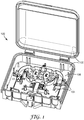
- FIG. 1 provides a perspective view of a network interface device 100 according to a first aspect of the present description.
- Network interface device 100 generally includes an enclosure body 102 and a tray 104.
- Tray 104 is securely mounted to an interior surface 106 of the enclosure, and includes a number of fiber management components.
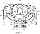
- Fiber management tray assembly 201 includes a first optical fiber 208 that is stored in loops around a slack storage system 210 in tray 204.
- the tray 204 can be constructed from a standard material, such as metal or plastic.
- the tray is constructed from a molded plastic material, e.g., a suitable polymer material, such as polycarbonate, polyamide, polypropylene, polyethylene or the like.
- optical fiber 208 may comprise a standard single mode or multimode optical fiber, such as SMF 28 (available from Corning Inc.).
- the optical fiber has a 900 ⁇ m outer diameter buffer coating (not including standard fiber jacketing), although optical fiber 208 can comprise any standard optical fiber buffered diameter, such as 250 ⁇ m, or fiber buffered diameters larger or smaller.
- the first end of the optical fiber 208 is pre-installed in a first mechanical fiber splice device 214.
- First mechanical fiber splice device 214 is securely mounted in a first fiber splice holding groove 216 that is integrally formed in tray 204.
- the first mechanical fiber splice device receives the first end 212 of the optical fiber after routing through the slack storage system.
- a fiber splice actuation mechanism 218 is positioned over the first mechanical fiber splice device 214.
- the fiber splice actuation mechanism 218 is capable of actuating the first mechanical fiber splice 214 by pressing on the actuation mechanism.
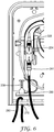
- the fiber splice actuation mechanism comprises a flexible cantilevered arm that is integral to the tray.
- a perspective view more clearly illustrating this element may be found in Figure 4 .
- fiber management tray assembly may include, as part of the fiber splice holding groove 216, an alignment channel 220 that facilitates optical fiber insertion into the first mechanical fiber splice device 214.
- the mechanical fiber splices described herein may be, e.g., 3MTM FIBRLOKTM II mechanical fiber optic splice device, available from 3M Company, of Saint Paul, Minnesota, or another conventional mechanical splice device.
- splice holding groove(s) and alignment channel(s) are formed as part of a splice holding section, which is integrally formed onto tray 204. In this manner, different splice inserts can be utilized to accommodate different types of mechanical splices.
- slack storage system 210 may include at least one fiber stay 222.
- Fiber stay 222 is positioned to ensure that the fiber 208 will remain in position, even when a mechanical splice device (such as first mechanical fiber splice device 214) is unactuated.
- Fiber stay 222 may, in some embodiments, be integrally formed in the tray and may, for example, be a plastic tab.
- Slack storage system 210 includes containment walls 246 that partly surround the system and provide a barrier from the mechanical splice device or devices.
- the system further includes dual hubs 248 around which the optical fiber 208 is routed, that provide for a minimum bend radius and also may, in certain embodiments, allow for figure-8 routing of the optical fiber.
- FIG 3 illustrates some further aspects of potential embodiments of fiber management trays according to the present description. Though not all elements from Figure 2 are included, they may also be included along with the elements described.
- Fiber management tray assembly further includes an adapter 224.
- Adapter 224 is mounted in a first adapter mounting mechanism 226 that is integrally formed in the tray. Adapter 224 is generally capable of receiving and coupling two connectors.
- Figure 4 provides a perspective view of the construction shown in Figure 3 .
- fiber management tray assembly may include a first connector 228 that is connected to the adapter 224. Second end of the first optical fiber 208 is installed in the first connector 228, such that optical fiber (potentially pigtail) 208 is routed from connector 228, looped around the slack storage system 210, and ultimately reaches first mechanical fiber splice 214. Where a fiber pigtail is used, the fiber pigtail end can be stripped and cleaved (flat or angled), or otherwise suitably prepared.
- connectors can be pre-installed into the adapter with a desired length of pigtail fiber exiting from the back end of the connector, where the end of that pigtail fiber can be prepared for splicing and inserted part way into the splice device.
- this initial connectorization can be completed in the factory, prior to field termination.
- Connectors used herein can include one or several different types of standard optical connectors, such as SC-type, FC-type, LC-type, and ST-type connectors.
- SC-type standard optical connector
- FC-type FC-type
- LC-type LC-type
- ST-type connectors ST-type connectors
- SC-APC angle polished connector
- the fiber management assembly may additionally include a second adapter mounting mechanism 230 that is integrally formed in the tray 204. Though not shown, a second adapter may be mounted into second adapter mounting mechanism 230.
- the first and second adapter mounting mechanisms may be, as illustrated in Figure 5 , on opposing sides of tray 204. Alternatively, the adapter mounting mechanisms can be disposed adjacent each other on the same area of the tray. For example, such as shown in Fig. 9 , the adapter mounting mechanisms can be mounted above the slack storage and opposite the fiber splice holding section.
- the fiber management tray may include a protective cover that is removably positioned over the tray and protects the first connector 228 and first mechanical fiber splice device 214, as well as offering further protection to fiber 208.
- This protective cover (not shown) may be transparent and contain holes that snap in to connect with the tray's integral anchor points 234.
- Tray assembly 201 may further include a strain relief device 236.
- Strain relief device 236 may be integral to the tray and is capable of providing strain relief to a drop cable or subscriber cable that travels over the tray. It may be positioned most appropriately near an entry port, where the tray is positioned in an enclosure.
- subscriber cable 280 may enter an enclosure at an inlet port 278.
- a second connector 241 at the end of the subscriber cable 280 is connected to adapter 224 in order to connect to first connector 228 and optical fiber 208.
- Appropriate subscriber cables for use in the present invention may be e.g., EZ-Bend® cables from OFS (Norcross, Georgia), such as EZ-Bend® 4.8 mm or 3.0 mm cables.
- the tray assembly further includes a second mechanical fiber splice device 238 that is securely mounted in a second fiber splice holding groove 240.
- Fiber splice holding groove 240 (shown unobstructed in Figure 2 ) is integrally formed in the tray 204 and runs parallel to the first fiber splice holding groove 216.
- fiber splice actuation mechanism 218 is used to actuate both the first mechanical fiber splice device and second mechanical device.
- the two mechanical fiber splice mechanisms may be actuated serially or sequentially.
- Second optical fiber 242 is routed to the opposing side 244 of first mechanical fiber splice device 214 from which the first optical fiber 208 terminates.
- Second optical fiber may be a 900 ⁇ m outer diameter buffered cladding (not including standard fiber jacketing), or could be a standard optical fiber buffered diameter, such as 250 ⁇ m, or fiber buffered diameters larger or smaller.
- the tray 204 and tray assemblies described herein may be securely mounted to an interior surface 206 of an enclosure 200.
- the entire construction of the enclosure with incorporated tray assembly may be understood as a network interface device.
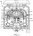
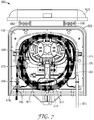
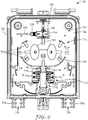
- FIG. 7 and 8 offer a different understanding of the present description.
- Top view of network interface device 600 illustrates that the device includes an enclosure 602.
- Enclosure body 602 may be made of any number of appropriate materials, such as an appropriate molded plastic.
- the enclosure body may be opened and closed by a hinge mechanism 682.
- Network interface device further includes a tray 604 that is securely mounted to an interior surface 606 of the enclosure body.
- the tray may include (as illustrated in the version of network interface device in Figure 8 , with elements removed for ease of illustration), a first adapter mounting mechanism 626 integrally formed in the tray, and an adapter 624 mounted into the mounting mechanism.
- the tray includes a first fiber splice holding groove 616 that is integrally formed in the tray, and a fiber splice actuation mechanism 618 that is positioned over the first fiber splice holding groove 616.
- the tray 604 includes a slack storage system 610.
- Network interface device 600 further includes a first connector 628 that is connected to the adapter 624.
- the first connector includes a first fiber pigtail 670 that extends from it.
- both fiber pigtail 670 and an optical fiber 672 from a drop cable 674 are routed around the slack storage system 610.
- First mechanical fiber splice device 614 is securely mounted in the first fiber splice holding groove 616, where the fiber splice actuation mechanism 618 is also positioned over the first mechanical fiber splice device 614.
- Fiber splice actuation mechanism is capable of actuating the first fiber splice device by pressing on the actuation mechanism.
- network interface device may include a protective cover (potentially transparent, e.g., a clear plastic cover) that is removably positioned over the tray and protects the first connector and first mechanical fiber splice device.
- the tray 604 may include a strain relief device 636 that is positioned proximate an entry port 678 into which the drop cable or subscriber cable 680 enters the enclosure. Subscriber cable 680 may be secured to the strain relief device using a cable tie or zip tie 698.
- Tray 604 may include a second fiber splice holding groove 684 that is positioned adjacent to and runs parallel to the first fiber splice groove 616.
- Network interface device 600 may include a second mechanical fiber splice device 638 that is securely mounted in second fiber splice holding groove 684.
- the fiber splice actuation mechanism 618 is positioned over the second mechanical fiber splice device, and is capable of actuating the second fiber splice device by pressing on the actuation mechanism.
- Network interface device 600 may include a second adapter 688 mounted in a second adapter mounting mechanism 630 in the tray.
- the first and second adapter mounting mechanisms may be positioned on opposing sides of the tray in one embodiment.
- first mechanical fiber splice device may be positioned generally between the first and second adapter mounting mechanisms.
- tray 604 may include a second strain relief device 692.
- Second strain relief device 692 may be positioned on an opposing side of the tray 604 from the strain relief device 636. Second strain relief device 692 is positioned proximate a second entry port 694 through which a drop cable or subscriber cable may enter the network interface device.
- the fiber management tray assembly includes the drop cable 274 that enters second inlet port 294, where the cable is routed through the slack storage system after optical fiber is removed and exposed as optical fiber 242.
- This fiber is spliced at first mechanical fiber splice device to optical fiber 208 which terminates at connector 228 disposed in adapter 224.
- a subscriber cable 280 may be routed to the tray (potentially through an inlet port 278 where the tray is in an enclosure) and connected via connector 241 to adapter 224. This provides the ultimate connection between the subscriber and drop cables.
- each of the subscriber and drop cables may be coiled within the enclosure and secured by strain relief devices at the inlet ports and cable management structures and or ties within the enclosure.
- FIG. 9 shows a tray is omitted, and the fiber management components are formed on an interior surface of the enclosure body.
- Fig. 9 shows a network interface device 700 having an enclosure body 702 with an interior surface 706.
- a fiber management assembly 701 having various fiber management areas, such as slack storage system 710, fiber splice holding section 715, and adapter holding section 725, can each have their components integrally formed onto interior surface 706.
- a first optical fiber 708 (only a portion of which is shown for simplicity) can be stored in slack storage system 710.
- the fiber can comprise any of the fibers described above.
- a first end of the optical fiber 708 can be pre-installed in a first mechanical fiber splice device 714 that is securely mounted in a first fiber splice holding groove 716 disposed in the splice holding section 715.
- the first mechanical fiber splice device receives the first end of the optical fiber after routing through the slack storage system.
- a fiber splice actuation mechanism 718 which is configured and operates in a pressing manner similar to that described above, can be provided and positioned over the first mechanical fiber splice device 714.
- pre-installing the optical fiber 708 in the in the slack storage system 710 of the fiber management assembly 701 prior to splice actuation allows an installer to avoid torsion effects on the optical fiber.
- a second mechanical splice device (not shown) may also be installed in splice holding section 715.
- fiber management assembly 701 may include, as part of the fiber splice holding section 715, an alignment channel that facilitates optical fiber insertion into the first mechanical fiber splice device 714.
- the mechanical fiber splices described herein may be, e.g., 3MTM FIBRLOKTM II mechanical fiber optic splice device, available from 3M Company, of Saint Paul, Minnesota, or another conventional mechanical splice device.
- splice holding groove(s) and alignment channel(s) may be formed as part of splice holding section 715 or may be provided as a separate splice insert mountable in splice holding section 715. In this manner, different splice inserts can be utilized to accommodate different types of mechanical splices.
- slack storage system 710 may include at least one fiber stay, such as those described above.
- Slack storage system 710 includes containment walls 746 that partly surround the slack storage system and provide a barrier from the mechanical splice device or devices.
- the slack storage system further includes dual hubs 748 around which the optical fiber 708 is routed, that provide for a minimum bend radius and also may, in certain examples, allow for figure-8 routing of the optical fiber.
- Fiber management assembly 701 further includes one or more adapters disposed in an adapter holding section 725.
- a first adapter such as adapter 724
- Adapter 724 can be mounted in a first adapter mounting mechanism 726 that is integrally formed in the adapter holding section.
- Adapter 724 is generally capable of receiving and coupling two connectors.
- a first connector 728 can be connected to the adapter 724.
- Connector 728 can comprise any of the connectors described previously.
- the second end of the first optical fiber 708 is installed in the first connector 728, such that optical fiber (potentially pigtail) 708 is routed from connector 728, looped around the slack storage system 710, and ultimately reaches first mechanical fiber splice 714.
- the fiber pigtail end can be prepared as described above.
- connectors can be pre-installed into the adapter with a desired length of pigtail fiber exiting from the back end of the connector, where the end of that pigtail fiber can be prepared for splicing and inserted part way into the splice device.
- this initial connectorization can be completed in the factory, prior to field termination.
- Fiber management assembly 701 may additionally include a second adapter mounting mechanism that is integrally formed in the adapter holding section 725 for holding a second adapter (not shown).
- the first and second adapter mounting mechanisms may be disposed adjacent each other in the adapter holding section.
- the fiber management assembly 701 may further include a plurality of protective tabs 732 that are positioned over the slack storage system 710 to help ensure that optical fiber (e.g. pigtails) and potentially exposed optical fiber from the drop cable routed through the slack storage system 710 are secured within the slack storage system, similar to tabs 232 described previously.
- a protective cover similar to that described above, may also be included.
- Fiber management assembly 701 may further include a strain relief device that is capable of providing strain relief to a drop cable or subscriber cable that travels within the assembly. It may be positioned most appropriately near an entry port, such as entry ports 778 and 794.
- Fig. 9 shows strain relief structures 779 and 793 disposed on an exterior surface of enclosure body 702 at the ports. Internal strain relief structures can also be provided within the enclosure body as previously described.
- a subscriber cable may enter network interface device 700 at inlet port 778. Before the cable is ultimately secured to the strain relief device by e.g., a zip or cable tie, or other fastener, a second connector at the end of the subscriber cable can be connected to adapter 724 in order to connect to first connector 728. Appropriate subscriber cables are described previously.
- a cover (not shown) can be hingedly mounted as part of the enclosure body to provide further protection to the fibers and fiber management components disposed in the network interface device 700.
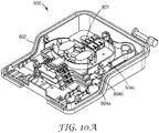
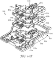
- a network interface device 800 can include multiple trays for fiber management and routing.
- Fig. 10A shows network interface device 800 having a tray assembly 801 mounted within enclosure body 802 that includes three fiber management trays 804a, 804b, and 804c in a stacked arrangement.
- a tray assembly 801 mounted within enclosure body 802 that includes three fiber management trays 804a, 804b, and 804c in a stacked arrangement.
- Fig. 10B shows a network interface device 800 having an enclosure body 802 with a first fiber management tray 804a mounted onto (or, alternatively, formed on) an interior surface of the enclosure body 802.
- Fiber management tray 804a can include various fiber management areas, such as slack storage 810a, fiber splice holding section 815a, and adapter holding section 825a.
- network interface device 800 includes a second fiber management tray 804b, which can include various fiber management areas, such as slack storage 810b, fiber splice holding section 815b, and adapter holding section 825b.
- network interface device 800 includes a third fiber management tray 804c, which can include various fiber management areas, such as slack storage 810c, fiber splice holding section 815c, and adapter holding section 825c. Each of these fiber management areas can be constructed the same as those like-numbered fiber management areas and components described previously, and are thus not described in further detail with respect to Fig. 10B . It should be noted that the enclosure body 802 can be configured to house a greater number of fiber management trays, depending on the application.
- the fiber management trays can each be the same, or they can have different fiber management components disposed thereon.
- each fiber management tray can include a mounting structures to allow for an additional tray to be pivotably mounted thereon. This configuration allows for a compact structure when in use, but also allows an installer to easily access each tray during installation or repair.
- network interface device 800 can accommodate a multi-fiber drop cable, with the ability to route each drop fiber from the multi-fiber drop cable to a particular fiber management tray having a splice device pre-installed thereon. Fiber routing can be accomplished in the same manner as described previously.
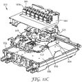
- a network interface device 900 can include a pre-installed splitter and patch panel for multi-subscriber and/or multi-dwelling applications.
- a network interface device 900 includes a patch panel assembly 960 having a patch panel tray 964, protective tabs 967 (to protect fibers routed to the patch panel), and a patch panel frame 965 disposed within enclosure body 902.
- Releasable latches 968 can be provided to maintain the position of the patch panel tray 964.
- the tray 964 can be constructed from a standard material, such as metal or plastic, such as those described previously.
- Patch panel frame 965 can accommodate multiple adapters 924a arranged in rows. While twelve adapters are shown in Fig. 11A , patch panel assembly 960 can be configured (e.g., sized) to accommodate a smaller or greater number of adapters. With multiple adapters housed within network interface device 900, multiple subscribers can be serviced from the same device.
- patch panel tray 964 is pivotably mounted to a fiber management tray 904, which is in turn mounted onto (or, alternatively, formed on) an interior surface 906 of the enclosure body 902.
- fiber management tray 904 can include various fiber management areas, such as slack storage 910, fiber splice holding section 915, and adapter holding section 925. Each of these fiber management areas can be constructed the same as those like-numbered fiber management areas and components described previously, and are thus not described in further detail with respect to Figs. 11A-11C .
- fiber management tray 904 can also house a splitter 990, such as a 1x4, 1x8, or 1x16 optical fiber splitter, or a combination of splitters (e.g., a 1x4 and 1x8 splitter), depending on the application.
- the splitter 990 can be a conventional optical fiber splitter, and can include a single input fiber and multiple pre-connectorized output fibers.
- splitter 990 is mounted onto tray 904 adjacent to the splice holding section.
- a drop cable fiber (not shown in Fig. 11B , but see fiber 242 from Fig. 5 ) is routed to a first end of a splice device mounted in the splice holding section 915 and the bare end of the splitter input fiber (not shown) is routed (via slack storage system 910) to a second end of the splice device.
- the splitter input fiber can be pre-installed in the splice device.
- the pre-connectorized output fibers can be routed to different adapters that are pre-installed in the patch panel 965.
- a fiber splice actuation mechanism 918 is positioned over the first mechanical fiber splice device. Similar to that described previously, the fiber splice actuation mechanism 918 is capable of actuating the mechanical fiber splice by pressing on the actuation mechanism. Pre-installation of the splitter fibers prior to splice actuation allows an installer to avoid torsion effects on the optical fibers. Subsequently, multiple subscriber cables (being pre-connectorized or field mounted onto connectors) can be connected to the patch panel, as appropriate.
Landscapes
- Physics & Mathematics (AREA)
- General Physics & Mathematics (AREA)
- Optics & Photonics (AREA)
- Light Guides In General And Applications Therefor (AREA)
Claims (9)
- Faserverwaltungskasettenanordnung, umfassend:
eine Kassette (204), ein Überlängenaufnahmesystem (210), das auf der Kassette (204) angeordnet ist, und einen ersten Lichtwellenleiter (208), der in Schleifen um das Überlängenaufnahmesystem (210) verstaut ist,wobei das erste Ende (212) des ersten Lichtwellenleiters (208) in eine erste mechanische Faserspleißvorrichtung (214) vorinstalliert ist,wobei die Faserverwaltungskasettenanordnung ferner eine zweite mechanische Faserspleißvorrichtung (238) umfasst,wobei die erste mechanische Faserspleißvorrichtung (214) fest in eine erste Faserspleißhaltenut (216) montiert ist, die in der Kassette (204) integral ausgebildet ist,wobei die zweite mechanische Faserspleißvorrichtung (238) fest in eine zweite Faserspleißhaltenut (240) montiert ist, die in der Kassette (204) integral ausgebildet ist und parallel zur ersten Faserspleißhaltenut (216) verläuft,und ferner umfassend einen zweiten Lichtwellenleiter (242), der zur gegenüberliegenden Seite der ersten mechanischen Faserspleißvorrichtung (214) geleitet ist, von der der erste Lichtwellenleiter (208) endet, gekennzeichnet durch einen Faserspleißbetätigungsmechanismus (218), der über der ersten mechanischen Faserspleißvorrichtung (214) und über der zweiten mechanischen Faserspleißvorrichtung (238) positioniert und dazu eingerichtet ist, die erste mechanische Faserspleißvorrichtung (214) und die zweite mechanische Faserspleißvorrichtung (238) durch Drücken auf den Betätigungsmechanismus (218) zu betätigen, wobei der Faserspleißbetätigungsmechanismus (218) einen flexiblen auskragenden Arm umfasst, der einstückig mit der Kassette (204) ist. - Faserverwaltungskasettenanordnung nach Anspruch 1, wobei das Überlängenaufnahmesystem (210) mindestens eine Faserstütze (222) umfasst, die dazu positioniert ist, sicherzustellen, dass der erste Lichtwellenleiter (208) in einer nicht betätigten mechanischen Spleißvorrichtung (214) positioniert bleibt.
- Faserverwaltungskasettenanordnung nach Anspruch 1, ferner umfassend einen Adapter (224), der in einen Adaptermontagemechanismus (226) montiert ist, wobei der Adaptermontagemechanismus (226) in der Kassette (204) integral ausgebildet ist.
- Faserverwaltungskasettenanordnung nach Anspruch 3, ferner umfassend einen ersten Stecker (228), der mit dem Adapter (224) verbunden ist, wobei das zweite Ende des ersten Lichtwellenleiters (208) in den ersten Stecker (228) installiert ist, und ferner umfassend einen zweiten Adapter, der in einen zweiten Adaptermontagemechanismus (230) montiert ist, wobei der zweite Adaptermontagemechanismus (230) in der Kassette (204) integral ausgebildet ist, wobei der erste und der zweite Adaptermontagemechanismus (226, 230) auf entgegengesetzten Seiten der Kassette (204) positioniert sind.
- Faserverwaltungskasettenanordnung nach Anspruch 1, wobei der erste Lichtwellenleiter (208) ein vorkonfektioniertes Pigtail ist.
- Faserverwaltungskasettenanordnung nach Anspruch 1, ferner umfassend eine Vielzahl von Schutzlaschen (232), die über dem Überlängenaufnahmesystem (210) positioniert sind.
- Faserverwaltungskasettenanordnung nach Anspruch 1, wobei die Kassette (204) ferner eine Zugentlastungsvorrichtung (236) umfasst, die für die Zugentlastung eines Verbindungskabels oder Teilnehmerkabels (280) sorgt.
- Netzwerkschnittstellenvorrichtung, umfassend:die Faserverwaltungskasettenanordnung (201) nach Anspruch 1;einen Gehäusekörper (102);wobei die Faserverwaltungskasettenanordnung (201) in dem Gehäusekörper (102) angeordnet ist,wobei die Faserverwaltungskasettenanordnung (201) ferner umfasst:einen Adaptermontageabschnitt;einen Adapter (224), der in einen Adaptermontagemechanismus (226) montiert ist, der in dem Adaptermontageabschnitt angeordnet ist, wobei der Adaptermontagemechanismus (226) auf der Kassette (204) der Faserverwaltungskasettenanordnung integral ausgebildet ist;einen ersten Stecker (228), der mit dem Adapter (224) verbunden ist, wobei sich der erste Lichtwellenleiter (208) von dem ersten Stecker (228) als ein erstes Faserpigtail erstreckt, wobei das erste Faserpigtail (208) und ein Lichtwellenleiter von einem Verbindungskabel (274) beide um das Überlängenaufnahmesystem (210) geleitet sind.
- Netzwerkschnittstellenvorrichtung nach Anspruch 8, ferner umfassend erste und zweite Zugentlastungsvorrichtungen, wobei die erste Zugentlastungsvorrichtung (636) auf einer Seite der Kassette (604) nahe einer Eintrittsöffnung (678) des Gehäusekörpers (102) positioniert ist, in der das Verbindungskabel in das Gehäuse eintreten kann, und die zweite Zugentlastungsvorrichtung (692) auf einer entgegengesetzten Seite der Kassette (604) von der ersten Zugentlastungsvorrichtung (636) positioniert ist, wobei die zweite Zugentlastungsvorrichtung nahe einer zweiten Eintrittsöffnung (694) in den Gehäusekörper (102) positioniert ist.
Priority Applications (1)
| Application Number | Priority Date | Filing Date | Title |
|---|---|---|---|
| PL15800100T PL3149520T3 (pl) | 2014-05-27 | 2015-05-27 | Zespoły do zarządzania włóknami oraz korytka i urządzenia interfejsu sieciowego zawierające takie zespoły i korytka |
Applications Claiming Priority (2)
| Application Number | Priority Date | Filing Date | Title |
|---|---|---|---|
| US201462003102P | 2014-05-27 | 2014-05-27 | |
| PCT/US2015/032657 WO2015183942A1 (en) | 2014-05-27 | 2015-05-27 | Fiber management assemblies and trays and network interface devices incorporating such assemblies and trays |
Publications (3)
| Publication Number | Publication Date |
|---|---|
| EP3149520A1 EP3149520A1 (de) | 2017-04-05 |
| EP3149520A4 EP3149520A4 (de) | 2018-01-24 |
| EP3149520B1 true EP3149520B1 (de) | 2021-09-01 |
Family
ID=54699708
Family Applications (1)
| Application Number | Title | Priority Date | Filing Date |
|---|---|---|---|
| EP15800100.8A Active EP3149520B1 (de) | 2014-05-27 | 2015-05-27 | Faserverwaltungsanordnungen und -schalen und netzwerkschnittstellenvorrichtungen mit solchen anordnungen und schalen |
Country Status (6)
| Country | Link |
|---|---|
| US (1) | US9341801B2 (de) |
| EP (1) | EP3149520B1 (de) |
| BR (1) | BR112016026503B1 (de) |
| MX (1) | MX356181B (de) |
| PL (1) | PL3149520T3 (de) |
| WO (1) | WO2015183942A1 (de) |
Families Citing this family (17)
| Publication number | Priority date | Publication date | Assignee | Title |
|---|---|---|---|---|
| CN104137366A (zh) * | 2011-07-11 | 2014-11-05 | 泰科电子瑞侃有限公司 | 带有熔接盒组件的通信机壳 |
| EP3224663B1 (de) * | 2014-11-26 | 2021-04-21 | CommScope Connectivity Belgium BVBA | Faserverwaltungskassette mit zweiseitiger aufbewahrungstasche |
| WO2016130292A1 (en) | 2015-02-13 | 2016-08-18 | 3M Innovative Properties Company | Telecommunication enclosure having integrated termination tools |
| WO2016191094A1 (en) * | 2015-05-27 | 2016-12-01 | 3M Innovative Properties Company | Fiber management assemblies and network interface devices incorporating such assemblies |
| USD813187S1 (en) * | 2016-04-29 | 2018-03-20 | Corning Optical Communications LLC | Telecommunication terminal cabinet |
| EP3695259B1 (de) * | 2017-10-09 | 2023-12-06 | CommScope Connectivity Belgium BVBA | Faseroptische telekommunikationswanne mit verbesserter zugänglichkeit und verwaltung |
| CN109696732B (zh) | 2017-10-24 | 2022-12-09 | 康普技术有限责任公司 | 光纤管理装置 |
| EP3714301A1 (de) * | 2017-11-23 | 2020-09-30 | Prysmian S.p.A. | Anschlussdose und verfahren zur verbindung von optischen kabeln |
| EP3528023B1 (de) * | 2018-02-15 | 2021-11-10 | ZweiCom-Hauff GmbH | Spleissmodul mit patcheinheit |
| CN112400128B (zh) * | 2019-06-13 | 2022-06-10 | 华为技术有限公司 | 一种光缆连接装置 |
| US10845561B1 (en) * | 2019-06-28 | 2020-11-24 | Afl Telecommunications Llc | Fiber optic cassettes and splice modules |
| WO2021226355A1 (en) * | 2020-05-06 | 2021-11-11 | Commscope Technologies Llc | Splice enclosure with connectorized patching functionality |
| WO2022035862A1 (en) * | 2020-08-14 | 2022-02-17 | Commscope Technologies Llc | Optical fiber management trays with interchangeable and adjustable fiber loop guides |
| US11740421B2 (en) | 2021-02-18 | 2023-08-29 | Commscope Technologies Llc | Communications panel system |
| US11971598B2 (en) | 2021-02-18 | 2024-04-30 | Commscope Technologies Llc | Tray arrangements for cassettes |
| EP4174546A1 (de) * | 2021-10-28 | 2023-05-03 | Corning Research & Development Corporation | Spleissablagesperrvorrichtung und verfahren zur verwendung |
| CA3238200A1 (en) * | 2021-11-19 | 2023-05-25 | Afl Telecommunications Llc | Closure and organizer assemblies therefor |
Family Cites Families (34)
| Publication number | Priority date | Publication date | Assignee | Title |
|---|---|---|---|---|
| US4911662A (en) * | 1988-12-20 | 1990-03-27 | Northern Telecom Limited | Distribution frame for telecommunications cable |
| US5734775A (en) | 1996-02-06 | 1998-03-31 | Vidacovich; Kenneth John | Method and system for fiber optic splice activation and deactivation within an optical fiber distribution frame |
| AU720876B2 (en) | 1996-06-14 | 2000-06-15 | Lucent Technologies Inc. | Signal transmission media routing arrangement |
| US5778122A (en) | 1996-12-24 | 1998-07-07 | Siecor Corporation | Fiber optic cable assembly for interconnecting optical fibers within a receptacle mounted within the wall of an enclosure |
| US6496641B1 (en) | 1999-08-12 | 2002-12-17 | Bellsouth Intellectual Property Corporation | Fiber optic interface device |
| US6802724B1 (en) | 1999-08-12 | 2004-10-12 | Bellsouth Intellectual Property Corporation | Fiber optic interface device |
| US6661961B1 (en) | 2000-11-01 | 2003-12-09 | Tyco Electronics Corporation | Fiber low profile network interface device |
| US6721484B1 (en) | 2002-09-27 | 2004-04-13 | Corning Cable Systems Llc | Fiber optic network interface device |
| US6804447B2 (en) | 2002-11-05 | 2004-10-12 | Adc Telecommunications, Inc. | Fiber panel with integrated couplers |
| JP3989853B2 (ja) * | 2003-02-14 | 2007-10-10 | 株式会社フジクラ | 光接続ユニット |
| JP2004333835A (ja) | 2003-05-07 | 2004-11-25 | Nec Corp | 光加入者線終端装置 |
| US7346253B2 (en) | 2003-12-24 | 2008-03-18 | Corning Cable Systems Llc | Fiber optic drop cable slack storage receptacle |
| JP4414215B2 (ja) | 2003-12-25 | 2010-02-10 | 日本アンテナ株式会社 | 光端末装置 |
| JP4160500B2 (ja) | 2003-12-25 | 2008-10-01 | 日本アンテナ株式会社 | 光端末装置 |
| NL1026832C2 (nl) | 2004-08-12 | 2006-02-14 | Genexis B V | Inrichting voor het aansluiten van apparaten op lichtgeleidende vezels. |
| US7333709B2 (en) | 2004-09-24 | 2008-02-19 | 3M Innovative Properties Company | Splice holder device |
| US20060067636A1 (en) * | 2004-09-24 | 2006-03-30 | 3M Innovative Properties Company | Connector and splice holder device |
| US20060153362A1 (en) | 2005-01-13 | 2006-07-13 | Bloodworth Stephen G | Network interface device for fiber optic communications network |
| US20060153516A1 (en) | 2005-01-13 | 2006-07-13 | Napiorkowski John J | Network interface device having integral slack storage compartment |
| EP1835319A1 (de) | 2006-03-13 | 2007-09-19 | British Telecommunications Public Limited Company | Netzanschlussgerät |
| US7619160B2 (en) | 2006-05-23 | 2009-11-17 | Corning Cable Systems Llc | Enclosure for housing communications equipment |
| US8135256B2 (en) | 2006-12-01 | 2012-03-13 | Adc Telecommunications, Inc. | Network interface device |
| US7349616B1 (en) | 2007-01-12 | 2008-03-25 | Corning Cable Systems Llc | Fiber optic local convergence points for multiple dwelling units |
| CN101398514B (zh) | 2007-09-28 | 2010-09-29 | 3M创新有限公司 | 用于信息插座的连接保持器 |
| WO2010077856A1 (en) | 2008-12-17 | 2010-07-08 | 3M Innovative Properties Company | Modular fiber distribution unit |
| DE102009008068B4 (de) | 2009-02-09 | 2014-03-27 | Kathrein-Werke Kg | Netzabschluss-Gehäuse für einen optischen Netzwerkabschluss |
| CA2789676A1 (en) | 2010-03-10 | 2011-09-15 | David L. Barron | Fiber optic cassette |
| CN101840039A (zh) | 2010-04-22 | 2010-09-22 | 深圳市华为安捷信电气有限公司 | 光纤终端盒 |
| CA2796356A1 (en) | 2010-04-23 | 2011-10-27 | Ccs Technology, Inc. | Removable fiber optic splice tray |
| US8660397B2 (en) * | 2010-04-30 | 2014-02-25 | Corning Cable Systems Llc | Multi-layer module |
| RU2577086C2 (ru) * | 2010-12-01 | 2016-03-10 | 3М Инновейтив Пропертиз Компани | Органайзер для оптоволокна и распределительная коробка |
| DE102011106987A1 (de) | 2011-07-06 | 2013-01-10 | Deutsche Telekom Ag | Netzabschluss-Einrichtung für optische Netzwerke |
| CN102692689B (zh) | 2012-06-15 | 2013-09-25 | 华为技术有限公司 | 光纤终端盒 |
| AR096262A1 (es) | 2013-05-14 | 2015-12-16 | Communications Systems Inc | Dispositivo de interfaz de red híbrido y apilable |
-
2015
- 2015-05-27 EP EP15800100.8A patent/EP3149520B1/de active Active
- 2015-05-27 WO PCT/US2015/032657 patent/WO2015183942A1/en active Application Filing
- 2015-05-27 PL PL15800100T patent/PL3149520T3/pl unknown
- 2015-05-27 MX MX2016014549A patent/MX356181B/es active IP Right Grant
- 2015-05-27 US US14/722,962 patent/US9341801B2/en active Active
- 2015-05-27 BR BR112016026503-3A patent/BR112016026503B1/pt active IP Right Grant
Also Published As
| Publication number | Publication date |
|---|---|
| MX356181B (es) | 2018-05-17 |
| EP3149520A4 (de) | 2018-01-24 |
| PL3149520T3 (pl) | 2022-01-24 |
| US20150346449A1 (en) | 2015-12-03 |
| BR112016026503B1 (pt) | 2022-06-07 |
| WO2015183942A1 (en) | 2015-12-03 |
| MX2016014549A (es) | 2017-02-20 |
| US9341801B2 (en) | 2016-05-17 |
| EP3149520A1 (de) | 2017-04-05 |
| BR112016026503A2 (de) | 2017-08-15 |
Similar Documents
| Publication | Publication Date | Title |
|---|---|---|
| EP3149520B1 (de) | Faserverwaltungsanordnungen und -schalen und netzwerkschnittstellenvorrichtungen mit solchen anordnungen und schalen | |
| US10001617B2 (en) | Fiber management assemblies and network interface devices incorporating such assemblies | |
| US10545305B2 (en) | Distribution device with incrementally added splitters | |
| US7653282B2 (en) | Multi-port optical connection terminal | |
| US6766094B2 (en) | Aerial closure for local convergence point | |
| US7740409B2 (en) | Multi-port optical connection terminal | |
| US10520692B2 (en) | Optical connection terminals for fiber optic communications networks | |
| US7302152B2 (en) | Overmolded multi-port optical connection terminal having means for accommodating excess fiber length | |
| US20060067636A1 (en) | Connector and splice holder device | |
| US20050207711A1 (en) | Optical termination pedestal | |
| US20080112681A1 (en) | Optical connection closure having at least one connector port | |
| US8649649B2 (en) | Fiber distribution hub with connectorized stub cables | |
| WO2009045396A9 (en) | Modular optical fiber cassettes and fiber management methods |
Legal Events
| Date | Code | Title | Description |
|---|---|---|---|
| STAA | Information on the status of an ep patent application or granted ep patent |
Free format text: STATUS: THE INTERNATIONAL PUBLICATION HAS BEEN MADE |
|
| PUAI | Public reference made under article 153(3) epc to a published international application that has entered the european phase |
Free format text: ORIGINAL CODE: 0009012 |
|
| STAA | Information on the status of an ep patent application or granted ep patent |
Free format text: STATUS: REQUEST FOR EXAMINATION WAS MADE |
|
| 17P | Request for examination filed |
Effective date: 20161114 |
|
| AK | Designated contracting states |
Kind code of ref document: A1 Designated state(s): AL AT BE BG CH CY CZ DE DK EE ES FI FR GB GR HR HU IE IS IT LI LT LU LV MC MK MT NL NO PL PT RO RS SE SI SK SM TR |
|
| AX | Request for extension of the european patent |
Extension state: BA ME |
|
| DAV | Request for validation of the european patent (deleted) | ||
| DAX | Request for extension of the european patent (deleted) | ||
| REG | Reference to a national code |
Ref country code: DE Ref legal event code: R079 Ref document number: 602015072923 Country of ref document: DE Free format text: PREVIOUS MAIN CLASS: G02B0006000000 Ipc: G02B0006440000 |
|
| A4 | Supplementary search report drawn up and despatched |
Effective date: 20180104 |
|
| RIC1 | Information provided on ipc code assigned before grant |
Ipc: G02B 6/44 20060101AFI20171221BHEP Ipc: G02B 6/38 20060101ALI20171221BHEP |
|
| RAP1 | Party data changed (applicant data changed or rights of an application transferred) |
Owner name: CORNING RESEARCH & DEVELOPMENT CORPORATION |
|
| STAA | Information on the status of an ep patent application or granted ep patent |
Free format text: STATUS: EXAMINATION IS IN PROGRESS |
|
| 17Q | First examination report despatched |
Effective date: 20190607 |
|
| STAA | Information on the status of an ep patent application or granted ep patent |
Free format text: STATUS: EXAMINATION IS IN PROGRESS |
|
| GRAP | Despatch of communication of intention to grant a patent |
Free format text: ORIGINAL CODE: EPIDOSNIGR1 |
|
| STAA | Information on the status of an ep patent application or granted ep patent |
Free format text: STATUS: GRANT OF PATENT IS INTENDED |
|
| INTG | Intention to grant announced |
Effective date: 20210316 |
|
| GRAS | Grant fee paid |
Free format text: ORIGINAL CODE: EPIDOSNIGR3 |
|
| GRAA | (expected) grant |
Free format text: ORIGINAL CODE: 0009210 |
|
| STAA | Information on the status of an ep patent application or granted ep patent |
Free format text: STATUS: THE PATENT HAS BEEN GRANTED |
|
| AK | Designated contracting states |
Kind code of ref document: B1 Designated state(s): AL AT BE BG CH CY CZ DE DK EE ES FI FR GB GR HR HU IE IS IT LI LT LU LV MC MK MT NL NO PL PT RO RS SE SI SK SM TR |
|
| REG | Reference to a national code |
Ref country code: GB Ref legal event code: FG4D |
|
| REG | Reference to a national code |
Ref country code: CH Ref legal event code: EP Ref country code: AT Ref legal event code: REF Ref document number: 1426822 Country of ref document: AT Kind code of ref document: T Effective date: 20210915 |
|
| REG | Reference to a national code |
Ref country code: DE Ref legal event code: R096 Ref document number: 602015072923 Country of ref document: DE |
|
| REG | Reference to a national code |
Ref country code: IE Ref legal event code: FG4D |
|
| REG | Reference to a national code |
Ref country code: LT Ref legal event code: MG9D |
|
| REG | Reference to a national code |
Ref country code: NL Ref legal event code: MP Effective date: 20210901 |
|
| PG25 | Lapsed in a contracting state [announced via postgrant information from national office to epo] |
Ref country code: HR Free format text: LAPSE BECAUSE OF FAILURE TO SUBMIT A TRANSLATION OF THE DESCRIPTION OR TO PAY THE FEE WITHIN THE PRESCRIBED TIME-LIMIT Effective date: 20210901 Ref country code: RS Free format text: LAPSE BECAUSE OF FAILURE TO SUBMIT A TRANSLATION OF THE DESCRIPTION OR TO PAY THE FEE WITHIN THE PRESCRIBED TIME-LIMIT Effective date: 20210901 Ref country code: SE Free format text: LAPSE BECAUSE OF FAILURE TO SUBMIT A TRANSLATION OF THE DESCRIPTION OR TO PAY THE FEE WITHIN THE PRESCRIBED TIME-LIMIT Effective date: 20210901 Ref country code: FI Free format text: LAPSE BECAUSE OF FAILURE TO SUBMIT A TRANSLATION OF THE DESCRIPTION OR TO PAY THE FEE WITHIN THE PRESCRIBED TIME-LIMIT Effective date: 20210901 Ref country code: ES Free format text: LAPSE BECAUSE OF FAILURE TO SUBMIT A TRANSLATION OF THE DESCRIPTION OR TO PAY THE FEE WITHIN THE PRESCRIBED TIME-LIMIT Effective date: 20210901 Ref country code: NO Free format text: LAPSE BECAUSE OF FAILURE TO SUBMIT A TRANSLATION OF THE DESCRIPTION OR TO PAY THE FEE WITHIN THE PRESCRIBED TIME-LIMIT Effective date: 20211201 Ref country code: BG Free format text: LAPSE BECAUSE OF FAILURE TO SUBMIT A TRANSLATION OF THE DESCRIPTION OR TO PAY THE FEE WITHIN THE PRESCRIBED TIME-LIMIT Effective date: 20211201 Ref country code: LT Free format text: LAPSE BECAUSE OF FAILURE TO SUBMIT A TRANSLATION OF THE DESCRIPTION OR TO PAY THE FEE WITHIN THE PRESCRIBED TIME-LIMIT Effective date: 20210901 |
|
| REG | Reference to a national code |
Ref country code: AT Ref legal event code: MK05 Ref document number: 1426822 Country of ref document: AT Kind code of ref document: T Effective date: 20210901 |
|
| PG25 | Lapsed in a contracting state [announced via postgrant information from national office to epo] |
Ref country code: LV Free format text: LAPSE BECAUSE OF FAILURE TO SUBMIT A TRANSLATION OF THE DESCRIPTION OR TO PAY THE FEE WITHIN THE PRESCRIBED TIME-LIMIT Effective date: 20210901 Ref country code: GR Free format text: LAPSE BECAUSE OF FAILURE TO SUBMIT A TRANSLATION OF THE DESCRIPTION OR TO PAY THE FEE WITHIN THE PRESCRIBED TIME-LIMIT Effective date: 20211202 |
|
| PG25 | Lapsed in a contracting state [announced via postgrant information from national office to epo] |
Ref country code: AT Free format text: LAPSE BECAUSE OF FAILURE TO SUBMIT A TRANSLATION OF THE DESCRIPTION OR TO PAY THE FEE WITHIN THE PRESCRIBED TIME-LIMIT Effective date: 20210901 |
|
| PG25 | Lapsed in a contracting state [announced via postgrant information from national office to epo] |
Ref country code: IS Free format text: LAPSE BECAUSE OF FAILURE TO SUBMIT A TRANSLATION OF THE DESCRIPTION OR TO PAY THE FEE WITHIN THE PRESCRIBED TIME-LIMIT Effective date: 20220101 Ref country code: SM Free format text: LAPSE BECAUSE OF FAILURE TO SUBMIT A TRANSLATION OF THE DESCRIPTION OR TO PAY THE FEE WITHIN THE PRESCRIBED TIME-LIMIT Effective date: 20210901 Ref country code: SK Free format text: LAPSE BECAUSE OF FAILURE TO SUBMIT A TRANSLATION OF THE DESCRIPTION OR TO PAY THE FEE WITHIN THE PRESCRIBED TIME-LIMIT Effective date: 20210901 Ref country code: RO Free format text: LAPSE BECAUSE OF FAILURE TO SUBMIT A TRANSLATION OF THE DESCRIPTION OR TO PAY THE FEE WITHIN THE PRESCRIBED TIME-LIMIT Effective date: 20210901 Ref country code: PT Free format text: LAPSE BECAUSE OF FAILURE TO SUBMIT A TRANSLATION OF THE DESCRIPTION OR TO PAY THE FEE WITHIN THE PRESCRIBED TIME-LIMIT Effective date: 20220103 Ref country code: NL Free format text: LAPSE BECAUSE OF FAILURE TO SUBMIT A TRANSLATION OF THE DESCRIPTION OR TO PAY THE FEE WITHIN THE PRESCRIBED TIME-LIMIT Effective date: 20210901 Ref country code: EE Free format text: LAPSE BECAUSE OF FAILURE TO SUBMIT A TRANSLATION OF THE DESCRIPTION OR TO PAY THE FEE WITHIN THE PRESCRIBED TIME-LIMIT Effective date: 20210901 Ref country code: CZ Free format text: LAPSE BECAUSE OF FAILURE TO SUBMIT A TRANSLATION OF THE DESCRIPTION OR TO PAY THE FEE WITHIN THE PRESCRIBED TIME-LIMIT Effective date: 20210901 Ref country code: AL Free format text: LAPSE BECAUSE OF FAILURE TO SUBMIT A TRANSLATION OF THE DESCRIPTION OR TO PAY THE FEE WITHIN THE PRESCRIBED TIME-LIMIT Effective date: 20210901 |
|
| REG | Reference to a national code |
Ref country code: DE Ref legal event code: R097 Ref document number: 602015072923 Country of ref document: DE |
|
| PLBE | No opposition filed within time limit |
Free format text: ORIGINAL CODE: 0009261 |
|
| STAA | Information on the status of an ep patent application or granted ep patent |
Free format text: STATUS: NO OPPOSITION FILED WITHIN TIME LIMIT |
|
| PG25 | Lapsed in a contracting state [announced via postgrant information from national office to epo] |
Ref country code: IT Free format text: LAPSE BECAUSE OF FAILURE TO SUBMIT A TRANSLATION OF THE DESCRIPTION OR TO PAY THE FEE WITHIN THE PRESCRIBED TIME-LIMIT Effective date: 20210901 Ref country code: DK Free format text: LAPSE BECAUSE OF FAILURE TO SUBMIT A TRANSLATION OF THE DESCRIPTION OR TO PAY THE FEE WITHIN THE PRESCRIBED TIME-LIMIT Effective date: 20210901 |
|
| 26N | No opposition filed |
Effective date: 20220602 |
|
| PG25 | Lapsed in a contracting state [announced via postgrant information from national office to epo] |
Ref country code: SI Free format text: LAPSE BECAUSE OF FAILURE TO SUBMIT A TRANSLATION OF THE DESCRIPTION OR TO PAY THE FEE WITHIN THE PRESCRIBED TIME-LIMIT Effective date: 20210901 |
|
| REG | Reference to a national code |
Ref country code: CH Ref legal event code: PL |
|
| REG | Reference to a national code |
Ref country code: BE Ref legal event code: MM Effective date: 20220531 |
|
| PG25 | Lapsed in a contracting state [announced via postgrant information from national office to epo] |
Ref country code: MC Free format text: LAPSE BECAUSE OF FAILURE TO SUBMIT A TRANSLATION OF THE DESCRIPTION OR TO PAY THE FEE WITHIN THE PRESCRIBED TIME-LIMIT Effective date: 20210901 Ref country code: LU Free format text: LAPSE BECAUSE OF NON-PAYMENT OF DUE FEES Effective date: 20220527 Ref country code: LI Free format text: LAPSE BECAUSE OF NON-PAYMENT OF DUE FEES Effective date: 20220531 Ref country code: CH Free format text: LAPSE BECAUSE OF NON-PAYMENT OF DUE FEES Effective date: 20220531 |
|
| REG | Reference to a national code |
Ref country code: FR Ref legal event code: PLFP Year of fee payment: 9 |
|
| PG25 | Lapsed in a contracting state [announced via postgrant information from national office to epo] |
Ref country code: BE Free format text: LAPSE BECAUSE OF NON-PAYMENT OF DUE FEES Effective date: 20220531 |
|
| PGFP | Annual fee paid to national office [announced via postgrant information from national office to epo] |
Ref country code: PL Payment date: 20230324 Year of fee payment: 9 |
|
| P01 | Opt-out of the competence of the unified patent court (upc) registered |
Effective date: 20230527 |
|
| PGFP | Annual fee paid to national office [announced via postgrant information from national office to epo] |
Ref country code: IE Payment date: 20230425 Year of fee payment: 9 Ref country code: FR Payment date: 20230412 Year of fee payment: 9 Ref country code: DE Payment date: 20230412 Year of fee payment: 9 |
|
| PGFP | Annual fee paid to national office [announced via postgrant information from national office to epo] |
Ref country code: GB Payment date: 20230412 Year of fee payment: 9 |
|
| PG25 | Lapsed in a contracting state [announced via postgrant information from national office to epo] |
Ref country code: HU Free format text: LAPSE BECAUSE OF FAILURE TO SUBMIT A TRANSLATION OF THE DESCRIPTION OR TO PAY THE FEE WITHIN THE PRESCRIBED TIME-LIMIT; INVALID AB INITIO Effective date: 20150527 |
|
| PG25 | Lapsed in a contracting state [announced via postgrant information from national office to epo] |
Ref country code: MK Free format text: LAPSE BECAUSE OF FAILURE TO SUBMIT A TRANSLATION OF THE DESCRIPTION OR TO PAY THE FEE WITHIN THE PRESCRIBED TIME-LIMIT Effective date: 20210901 Ref country code: CY Free format text: LAPSE BECAUSE OF FAILURE TO SUBMIT A TRANSLATION OF THE DESCRIPTION OR TO PAY THE FEE WITHIN THE PRESCRIBED TIME-LIMIT Effective date: 20210901 |