EP3148306A1 - Lead component mounting apparatus and lead component mounting method - Google Patents
Lead component mounting apparatus and lead component mounting method Download PDFInfo
- Publication number
- EP3148306A1 EP3148306A1 EP14892370.9A EP14892370A EP3148306A1 EP 3148306 A1 EP3148306 A1 EP 3148306A1 EP 14892370 A EP14892370 A EP 14892370A EP 3148306 A1 EP3148306 A1 EP 3148306A1
- Authority
- EP
- European Patent Office
- Prior art keywords
- lead wires
- lead
- component
- main body
- portions
- Prior art date
- Legal status (The legal status is an assumption and is not a legal conclusion. Google has not performed a legal analysis and makes no representation as to the accuracy of the status listed.)
- Granted
Links
Images




Classifications
-
- H—ELECTRICITY
- H05—ELECTRIC TECHNIQUES NOT OTHERWISE PROVIDED FOR
- H05K—PRINTED CIRCUITS; CASINGS OR CONSTRUCTIONAL DETAILS OF ELECTRIC APPARATUS; MANUFACTURE OF ASSEMBLAGES OF ELECTRICAL COMPONENTS
- H05K13/00—Apparatus or processes specially adapted for manufacturing or adjusting assemblages of electric components
- H05K13/04—Mounting of components, e.g. of leadless components
- H05K13/0473—Cutting and clinching the terminal ends of the leads after they are fitted on a circuit board
-
- H—ELECTRICITY
- H05—ELECTRIC TECHNIQUES NOT OTHERWISE PROVIDED FOR
- H05K—PRINTED CIRCUITS; CASINGS OR CONSTRUCTIONAL DETAILS OF ELECTRIC APPARATUS; MANUFACTURE OF ASSEMBLAGES OF ELECTRICAL COMPONENTS
- H05K3/00—Apparatus or processes for manufacturing printed circuits
- H05K3/30—Assembling printed circuits with electric components, e.g. with resistors
- H05K3/306—Assembling printed circuits with electric components, e.g. with resistors with lead-in-hole components
-
- H—ELECTRICITY
- H05—ELECTRIC TECHNIQUES NOT OTHERWISE PROVIDED FOR
- H05K—PRINTED CIRCUITS; CASINGS OR CONSTRUCTIONAL DETAILS OF ELECTRIC APPARATUS; MANUFACTURE OF ASSEMBLAGES OF ELECTRICAL COMPONENTS
- H05K13/00—Apparatus or processes specially adapted for manufacturing or adjusting assemblages of electric components
- H05K13/04—Mounting of components, e.g. of leadless components
- H05K13/0404—Pick-and-place heads or apparatus, e.g. with jaws
- H05K13/0408—Incorporating a pick-up tool
Definitions
- the present invention relates to a lead component mounting machine which mounts lead components onto a circuit board to assemble an electronic circuit.
- PTL 1 and PTL 2 describe a lead component mounting machine provided with a component insertion device which inserts a lead wire of a lead component into a through-hole of a circuit board from one side, and a cut-and-clinch device which cuts and bends a protruding portion of the lead wire which protrudes from the other side of the circuit board.
- a lead wire of an axial lead component is held by a chuck on portions facing both sides of a component main body, and is inserted into a through-hole.
- the protruding portion of the lead wire is cut and bent from the other side.
- the lead wire of the lead component is held in a state of being pinched by a pair of pawl portions, and is inserted into a through-hole. Subsequently, the holding by the pair of pawl portions is released, and the component main body is pushed downward by a pushing-in device. In a state in which the component main body is pushed in by the pushing-in device, the protruding portion of the lead wire is cut and bent.
- the task of the present invention is to suppress the load which is borne by the lead component in a case in which the lead wire of the lead component is cut and clinched.
- a lead wire is cut and clinched in a state of being pinched from both sides by pawl portions.
- a tensile force is applied to the lead wire, caused by the cut-and-clinch operation; however, since the lead wire is in a state of being pinched from both sides by the pawl portions, the tensile force is rendered difficult to transmit to the component main body side of the lead component. As a result, it is possible to reduce the tensile force which is applied to an attachment section of the lead wire of the component main body, and it is possible to suppress the load borne by the lead component.
- the lead component mounting machine which is a type of automated assembly apparatus includes (a) an assembly apparatus main body 10, (b) a board conveyance device 12, (c) a component supplying device 14, (d) a component insertion device 16, (e) a cut-and-clinch device 18, and the like.
- the board conveyance device 12 conveys and holds a circuit board P (hereinafter, briefly referred to as board P) in a horizontal posture.
- x is a conveyance direction of the board P by the board conveyance device 12
- y is a width direction of the board P
- z is a thickness direction of the board P, that is, the vertical direction of the lead component mounting machine.
- the x-direction, the y-direction, and the z-direction orthogonally intersect each other.
- the component supplying device 14 supplies components to be mounted onto the board P, for example, the component supplying device 14 may include a plurality of tape feeders, may include a plurality of trays, and the like. In the present embodiment, a lead component in which a plurality of lead wires and a component main body are integrally formed is supplied.
- the component insertion device 16 is provided above the board conveyance device 12, receives the lead component which is supplied in the component supplying device 14, and inserts the lead wires of the lead component into a through-hole which is provided in a predetermined position among a plurality of through-holes which are formed in the board P which is held by the board conveyance device 12. Description will be given of the component insertion device 16 later.
- the cut-and-clinch device 18 is a device which is provided under the board conveyance device 12, cuts a portion, which protrudes from the bottom (the other side) of the board P, of the lead wire of the lead component which is inserted from above (one side) into a predetermined through-hole of the plurality of through-holes which are formed in the board P to a predetermined length, bends the lead wire along the reverse surface of the board P, and thus, temporarily fixes the lead component to the board P.
- the cut-and-clinch device 18 includes a cut-and-clinch unit 20, and a unit moving device 22 which causes the cut-and-clinch device 20 to move (including linear movement and rotation).
- the cut-and-clinch unit 20 includes (a) a unit main body 28, (b) a pair of first movable sections 30a and b which are held by the unit main body 28 to be capable of moving linearly in the horizontal direction, (c) a pair of second movable sections 32a and b which are held by the first movable sections 30a and b, respectively, to be capable of relative movement in the horizontal direction, (d) a pitch changing device 34 which is provided on the unit main body 28 and changes the interval (the pitch) between the pair of first movable sections 30a and b by causing the pair of first movable sections 30a and b to approach and separate in relation to each other, (e) movable blade driving devices 36a and b which cause the second movable sections 32a and b to move relative to the first movable sections 30a and b, respectively, and the like.
- the pair of first movable sections 30a and b include lead wire insertion holes 38a and b which extend in the vertical direction.
- the lead wire insertion holes 38a and b include openings in the top end surfaces of the first movable sections 30a and b, and the opening edges thereof are stationary blades 40a and b.
- the top end portions of the second movable sections 32a and b are substantially L-shaped and include a portion which extends upward and a portion which is bent approximately at a right angle thereto.
- Blade-forming sections 44a and b which are the portions which are bent at a right angle are positioned above the top end surfaces of the first movable sections 30a and b, and lead wire guide holes 46a and b which penetrate in the vertical direction are formed in portions facing the openings of the lead wire insertion holes 38a and b.
- the bottom end opening edges of the lead wire guide holes 46a and b of the blade-forming sections 44a and b are movable blades 48a and b.
- the lead wires which extend into the lead wire insertion holes 38a and b are cut and bent due to the pair of second movable sections 32a and b being caused to approach and separate in relation to each other by the movable blade driving devices 36a and b.
- the unit moving device 22 includes an x-direction moving device 52 which causes the cut-and-clinch unit 20 to move in the x-direction, a y-direction moving device 53 which causes the cut-and-clinch unit 20 to move in the y-direction, a z-direction moving device 54 which causes the cut-and-clinch unit 20 to move in the z-direction, a ⁇ -rotation device 55 which causes the cut-and-clinch unit 20 to rotate around a vertical line, and the like.
- the component insertion device 16 includes two work heads 60 and 61, and a work head moving device 62.
- the work head moving device 62 includes an x-direction moving device 64, a y-direction moving device 65, and z-direction moving devices 66 and 67.
- the work heads 60 and 61 are caused to move integrally to an arbitrary position in a horizontal plane by the x-direction moving device 64 and the y-direction moving device 65, and may be caused to move in the z-direction individually and independently by the z-direction moving devices 66 and 67, respectively.
- the work head 60 which is one of the two work heads, is provided with a component holding tool 68 (for example, it is possible to use a chuck, a suction nozzle, or the like) which holds the lead component.
- a camera 70 is provided to be capable of moving integrally with the work head 60.
- the chuck 68 illustrated in Figs. 5(a) to (c) is attached as the lead component holding tool (which may also be referred to as a lead component mounting tool).
- the lead component A is a radial lead component, and two lead wires La and b are attached to a component main body h in parallel.
- the chuck 68 pinches and holds the two lead wires La and b of the lead component A from both sides in the direction in which the two lead wires La and b are lined up.
- the chuck 68 includes (a) a chuck main body 72, (b) a pair of pawl portions 74a and b which are attached to the chuck main body 72 to be swingable, (c) a swing device 76 which causes the pair of pawl portions 74a and b to swing, (d) a pushing-in device 78 which pushes in the lead component A, and the like.
- the pawl portions 74a and b are substantially L-shaped, and include base end sections 80a and b which extend in the z-direction, and holding sections 82a and b which extend out from the base end sections 80a and b in a substantially horizontal direction. As illustrated in Fig.
- a recessed section 83b which is recessed in a protruding shape on one of the mutually-facing sides of the holding sections 82a and b (in the present embodiment, the side of the holding section 82b which faces the holding section 82a), and the lead wires La and b are held in a state of being accommodated by the recessed section 83b in a state of being pinched by the pair of holding sections 82a and b.
- the swing device 76 includes an air cylinder as a driving source which is not illustrate, and a swing mechanism 84.
- the swing mechanism 84 includes (a) a driving member 85 which extends in the horizontal direction and is provided in a fixed manner on a rod which serves as an output member of the air cylinder, (b) two first members 86p and q which are joined to both end portions of the driving member 85 to be relatively swingable, (c) second members 88p and q which are substantially L-shaped, one end portion of each is joined to the two first members 86p and q to be swingable, the pawl portions 74a and b are fixed integrally to the other end portion to be swingable, and the middle portion is joined, to be swingable, to a swing shaft 87 which is provided on the chuck main body 72, and the like.
- the second members 88p and q are caused to swing around the swing shaft 87, and the pair of pawl portions 74a and b are caused to approach or separate in relation to each other.
- the pair of pawl portions 74a and b are caused to approach each other by causing the driving member 85 to move upward, and the pair of pawl portions 74a and b are caused to separate from each other by causing the driving member 85 to move downward.
- the approaching and separating of the pair of claws 76a and b is controlled by controlling the air supply state of the air cylinder.
- the pushing-in device 78 includes (a) a pushing-in device main body 90 which is provided on the chuck main body 72 to be capable of moving in the z-direction (capable of being lifted and lowered), (b) a pressing member 92 which is attached to the bottom end portion of the pushing-in device main body 90, and (c) a lifting and lowering device 94 which lifts and lowers the pushing-in device main body 90 in relation to the chuck main body 72.
- the lifting and lowering device 94 may include an air cylinder which serves as a driving source which is not illustrated, and a pair of guide mechanisms 96r and s which are provided between the chuck main body 72 and the pushing-in device main body 90.
- the guide mechanisms 96r and s include the chuck main body 72, long holes 97r and s which are provided on both end portions in the horizontal direction of the pushing-in device main body 90 and extend in the z-direction, and two each of engaging protruding sections 98r and s which are attached to the chuck main body 72, and the long holes 97r and s and the engaging protruding sections 98r and s are engaged with each other to be capable of relative movement. It is possible to cause the main body 90 to be lifted and lowered along the guide mechanisms 96r and s, and to cause the pressing member 92 to be lifted and lowered by controlling the air supply state in the air cylinder which is the driving source.
- the swing device 76 and the lifting and lowering device 94 are not limited to using air cylinders as driving sources, and may include electric motors or the like.
- the lead component mounting machine is controlled by a main control device 100, the main constituent of which is a computer.
- a component supply control section 102, a board conveyance control section 104, a component insertion control section 106, a cut-and-clinch control section 108, and the like, the main constituent of which is a computer, are connected to the main control device 100 to be capable of mutual communication.
- the control sections 102 to 108 control the component supplying device 14, the board conveyance device 12, the component insertion device 16, and the cut-and-clinch device 18 described earlier, respectively.
- control section for each device such as the component supplying device 14, all of the devices may be controlled based on commands of the main control device 100, or the like, and the configuration of the control device is not limited to that described in the present embodiment.
- the two lead wires La and b of the lead component A are inserted by the component insertion device 16 into two through-holes Qa and b which are formed in predetermined positions on the board P. Meanwhile, the two lead wires La and b are cut and bent at a predetermined length in the below of the board P by the cut-and-clinch device 18.
- the component main body h of the lead component A is pushed in by the pushing-in device 78 until coming into contact with an upper surface S1 of the board P, and in this state, the cutting and clinching is performed.
- the cut-and-clinch device 18 the second movable sections 32a and b are caused to move in the horizontal direction.
- the lead wires La and b are cut by the stationary blades 40a and b and the movable blades 48a and b, and the lead wires La and b are bent by an opening peripheral portion of the lead wire guide holes 46a and b of the second movable sections 32a and b and a bottom surface S2 of the board P.
- the top end surfaces of the second movable sections 32a and b are in positions in close proximity to the bottom surface S2 of the board P.
- the lead wires La and b have a thickness (a diameter), and there is a gap between the lead wires La and b and the through-holes Qa and b.
- the cutting and clinching is performed in a state in which the lead wires La and b are pinched from both sides at a portion which is higher than the board P by the chuck 68.
- a pawl portion movement control section, and a pushing-in device control device are configured by the component insertion control section 106 and the like.
- the operation of (1) which is described above and illustrated in Fig. 7 (a) corresponds to a component insertion process
- the operation of (4) which is described above and illustrated in Fig. 7(c) corresponds to the cutting and clinching process.
- the lead component holding tool may be the one which has the structure illustrated in Figs. 9(a) and (b ).
- a chuck 110 is attached as the lead component holding tool.
- the chuck 110 is a slide-type chuck, and includes (a) a pair of pawl portions 112a and b which are capable of approaching and separating in relation to each other, (b) a spacer 114 which is positioned between the pair of pawl portions 112a and b, (c) an approaching and separating device 116 which causes the pair of pawl portions 112a and b to approach and separate, (d) a pushing-in device 118, and the like.
- the approaching and separating device 116 includes a driving source such as an air cylinder which is not illustrated, a pair of sliders 120a and b which are caused to approach and separate in relation to each other in the horizontal direction by the driving source, and the like, and the pawl portions 112a and b are attached to the pair of sliders a and b to be capable of moving integrally therewith.
- a driving source such as an air cylinder which is not illustrated
- a pair of sliders 120a and b which are caused to approach and separate in relation to each other in the horizontal direction by the driving source, and the like, and the pawl portions 112a and b are attached to the pair of sliders a and b to be capable of moving integrally therewith.
- the spacer 114 is positioned between the two lead wires La and b of the lead component A, and the width of the spacer 114 is a size corresponding to the interval between the lead wires La and b of the lead component A.
- a protrusion-shaped recessed section is provided on the spacer side of each of the pair of pawl portions 112a and b, and the lead wires La and b are held by the pawl portions 112a and b and the spacer 114 in a state of being stored in the recessed section.
- Each of the two lead wires La and b is held in a state of being pinched from both sides by the spacer 114 and the pawl portions 112a and b, that is, by the two pawl portions (112a, 114), and (112b, 114).
- the lead component which is mounted by the present lead component mounting machine is not an issue.
- the lead component may have three or more lead wires. In this case, two of the three or more lead wires are cut and clinched in a state of being pinched and held by one pair or two pairs of pawl portions.
- the lead wires of the lead component are short or the like, the lead wires may be bent without being cut by the cut-and-clinch device. In a case in which the lead wires do not reach the cutting section included in the cut-and-clinch device, the lead wires are bent without being cut.
- 16 component insertion device
- 18 cut-and-clinch device
- 30 first movable section
- 32 second movable section
- 68 chuck
- 74a and b pawl portion
- 76 swing device
- 78 pushing-in device
- 82a and b clamping section
- 112a and b pawl portion
- 114 spacer
Landscapes
- Engineering & Computer Science (AREA)
- Manufacturing & Machinery (AREA)
- Microelectronics & Electronic Packaging (AREA)
- Supply And Installment Of Electrical Components (AREA)
Abstract
Description
- The present invention relates to a lead component mounting machine which mounts lead components onto a circuit board to assemble an electronic circuit.
-
PTL 1 andPTL 2 describe a lead component mounting machine provided with a component insertion device which inserts a lead wire of a lead component into a through-hole of a circuit board from one side, and a cut-and-clinch device which cuts and bends a protruding portion of the lead wire which protrudes from the other side of the circuit board. - In the lead component mounting machine described in
PTL 1, a lead wire of an axial lead component is held by a chuck on portions facing both sides of a component main body, and is inserted into a through-hole. In a state in which the lead wire and the component main body are held by the chuck, the protruding portion of the lead wire is cut and bent from the other side. In the lead component mounting machine described inPTL 2, the lead wire of the lead component is held in a state of being pinched by a pair of pawl portions, and is inserted into a through-hole. Subsequently, the holding by the pair of pawl portions is released, and the component main body is pushed downward by a pushing-in device. In a state in which the component main body is pushed in by the pushing-in device, the protruding portion of the lead wire is cut and bent. -
- PTL 1:
JP-A-5-175696 - PTL 2:
JP-A-2002-261493 - The task of the present invention is to suppress the load which is borne by the lead component in a case in which the lead wire of the lead component is cut and clinched.
- In a lead component mounting machine according to the present invention, a lead wire is cut and clinched in a state of being pinched from both sides by pawl portions.
- A tensile force is applied to the lead wire, caused by the cut-and-clinch operation; however, since the lead wire is in a state of being pinched from both sides by the pawl portions, the tensile force is rendered difficult to transmit to the component main body side of the lead component. As a result, it is possible to reduce the tensile force which is applied to an attachment section of the lead wire of the component main body, and it is possible to suppress the load borne by the lead component.
-
- [
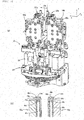
Fig. 1] Fig. 1 is a perspective view illustrating a lead component mounting machine which is an embodiment of the present invention. In the present lead component mounting machine, the lead component mounting method which is an embodiment of the present invention is carried out. - [
Fig. 2] Fig. 2 is a perspective view of a cut-and-clinch device and a board conveyance device which are included in the lead component mounting machine. - [
Fig. 3] Fig. 3(a) is a perspective view of a cut-and-clinch unit which is included in the cut-and-clinch device.Fig. 3(b) is a sectional diagram of a portion of the cut-and-clinch unit. - [
Fig. 4] Fig. 4 is a perspective view illustrating a component insertion device which is included in the lead component mounting machine. - [
Fig. 5] Fig. 5(a) is a side surface view of a chuck which is attached to a work head of the component insertion device.Fig. 5(b) is a rear surface view of the chuck.Fig. 5(c) is a front surface view of the chuck. - [
Fig. 6] Fig. 6 is a block diagram conceptually illustrating a control device of the lead component mounting machine. - [
Fig. 7] Figs. 7(a) to 7(c) are diagrams of operations of the chuck and the cut-and-clinch device. - [
Fig. 8] Figs. 8 are diagrams illustrating forces acting on a lead component A in a case in which cutting and clinching is performed by the cut-and-clinch device. - [
Fig. 9] Fig. 9 (a) is a side surface view of a different chuck which is attached to the work head.Fig. 9 (b) is a front surface view of the chuck. - Hereinafter, description will be given of an embodiment of the present invention with reference to the drawings. In addition to the embodiment described below, it is possible to embody the present invention with various modifications and improvements based on the knowledge of a person skilled in the art.
- As illustrated in
Fig. 1 , the lead component mounting machine which is a type of automated assembly apparatus includes (a) an assembly apparatusmain body 10, (b) aboard conveyance device 12, (c) acomponent supplying device 14, (d) acomponent insertion device 16, (e) a cut-and-clinch device 18, and the like. - The
board conveyance device 12 conveys and holds a circuit board P (hereinafter, briefly referred to as board P) in a horizontal posture. InFig. 1 , x is a conveyance direction of the board P by theboard conveyance device 12, y is a width direction of the board P, and z is a thickness direction of the board P, that is, the vertical direction of the lead component mounting machine. The x-direction, the y-direction, and the z-direction orthogonally intersect each other. - The
component supplying device 14 supplies components to be mounted onto the board P, for example, thecomponent supplying device 14 may include a plurality of tape feeders, may include a plurality of trays, and the like. In the present embodiment, a lead component in which a plurality of lead wires and a component main body are integrally formed is supplied. - The
component insertion device 16 is provided above theboard conveyance device 12, receives the lead component which is supplied in thecomponent supplying device 14, and inserts the lead wires of the lead component into a through-hole which is provided in a predetermined position among a plurality of through-holes which are formed in the board P which is held by theboard conveyance device 12. Description will be given of thecomponent insertion device 16 later. - The cut-and-
clinch device 18 is a device which is provided under theboard conveyance device 12, cuts a portion, which protrudes from the bottom (the other side) of the board P, of the lead wire of the lead component which is inserted from above (one side) into a predetermined through-hole of the plurality of through-holes which are formed in the board P to a predetermined length, bends the lead wire along the reverse surface of the board P, and thus, temporarily fixes the lead component to the board P. As illustrated inFigs. 2 and3 , the cut-and-clinch device 18 includes a cut-and-clinch unit 20, and aunit moving device 22 which causes the cut-and-clinch device 20 to move (including linear movement and rotation). - As illustrated in
Fig. 3 (a) , the cut-and-clinch unit 20 includes (a) a unitmain body 28, (b) a pair of firstmovable sections 30a and b which are held by the unitmain body 28 to be capable of moving linearly in the horizontal direction, (c) a pair of secondmovable sections 32a and b which are held by the firstmovable sections 30a and b, respectively, to be capable of relative movement in the horizontal direction, (d) apitch changing device 34 which is provided on the unitmain body 28 and changes the interval (the pitch) between the pair of firstmovable sections 30a and b by causing the pair of firstmovable sections 30a and b to approach and separate in relation to each other, (e) movableblade driving devices 36a and b which cause the secondmovable sections 32a and b to move relative to the firstmovable sections 30a and b, respectively, and the like. - As illustrated in
Fig. 3(b) , the pair of firstmovable sections 30a and b include leadwire insertion holes 38a and b which extend in the vertical direction. The leadwire insertion holes 38a and b include openings in the top end surfaces of the firstmovable sections 30a and b, and the opening edges thereof arestationary blades 40a and b. In comparison, the top end portions of the secondmovable sections 32a and b are substantially L-shaped and include a portion which extends upward and a portion which is bent approximately at a right angle thereto. Blade-formingsections 44a and b which are the portions which are bent at a right angle are positioned above the top end surfaces of the firstmovable sections 30a and b, and leadwire guide holes 46a and b which penetrate in the vertical direction are formed in portions facing the openings of the leadwire insertion holes 38a and b. The bottom end opening edges of the leadwire guide holes 46a and b of the blade-formingsections 44a and b aremovable blades 48a and b. The lead wires which extend into the leadwire insertion holes 38a and b are cut and bent due to the pair of secondmovable sections 32a and b being caused to approach and separate in relation to each other by the movableblade driving devices 36a and b. - As illustrated in
Fig. 2 , theunit moving device 22 includes anx-direction moving device 52 which causes the cut-and-clinch unit 20 to move in the x-direction, a y-direction moving device 53 which causes the cut-and-clinch unit 20 to move in the y-direction, a z-direction moving device 54 which causes the cut-and-clinch unit 20 to move in the z-direction, a θ-rotation device 55 which causes the cut-and-clinch unit 20 to rotate around a vertical line, and the like. - As illustrated in
Fig. 4 , thecomponent insertion device 16 includes twowork heads head moving device 62. The workhead moving device 62 includes anx-direction moving device 64, a y-direction moving device 65, and z-direction moving devices work heads x-direction moving device 64 and the y-direction moving device 65, and may be caused to move in the z-direction individually and independently by the z-direction moving devices work head 60, which is one of the two work heads, is provided with a component holding tool 68 (for example, it is possible to use a chuck, a suction nozzle, or the like) which holds the lead component. Acamera 70 is provided to be capable of moving integrally with thework head 60. - In the present embodiment, the
chuck 68 illustrated inFigs. 5(a) to (c) is attached as the lead component holding tool (which may also be referred to as a lead component mounting tool). The lead component A is a radial lead component, and two lead wires La and b are attached to a component main body h in parallel. Thechuck 68 pinches and holds the two lead wires La and b of the lead component A from both sides in the direction in which the two lead wires La and b are lined up. Thechuck 68 includes (a) a chuckmain body 72, (b) a pair ofpawl portions 74a and b which are attached to the chuckmain body 72 to be swingable, (c) aswing device 76 which causes the pair ofpawl portions 74a and b to swing, (d) a pushing-indevice 78 which pushes in the lead component A, and the like. - The
pawl portions 74a and b are substantially L-shaped, and includebase end sections 80a and b which extend in the z-direction, and holdingsections 82a and b which extend out from thebase end sections 80a and b in a substantially horizontal direction. As illustrated inFig. 5(a) , in plan view, arecessed section 83b which is recessed in a protruding shape on one of the mutually-facing sides of theholding sections 82a and b (in the present embodiment, the side of theholding section 82b which faces theholding section 82a), and the lead wires La and b are held in a state of being accommodated by therecessed section 83b in a state of being pinched by the pair ofholding sections 82a and b. Specifically, since twosurfaces 83p and q which form therecessed section 83b and another (the side of theholding section 82a which faces theholding section 82b)surface 83a are the contact surfaces of the lead wires La and b, the lead wires La and b are held by the friction force between the lead wires La and b and the threecontact surfaces 83p, q, and 83a. - The
swing device 76 includes an air cylinder as a driving source which is not illustrate, and aswing mechanism 84. Theswing mechanism 84 includes (a) a drivingmember 85 which extends in the horizontal direction and is provided in a fixed manner on a rod which serves as an output member of the air cylinder, (b) twofirst members 86p and q which are joined to both end portions of the drivingmember 85 to be relatively swingable, (c)second members 88p and q which are substantially L-shaped, one end portion of each is joined to the twofirst members 86p and q to be swingable, thepawl portions 74a and b are fixed integrally to the other end portion to be swingable, and the middle portion is joined, to be swingable, to aswing shaft 87 which is provided on the chuckmain body 72, and the like. - If the driving
member 85 is caused to move in the z-direction by the air cylinder, thesecond members 88p and q are caused to swing around theswing shaft 87, and the pair ofpawl portions 74a and b are caused to approach or separate in relation to each other. The pair ofpawl portions 74a and b are caused to approach each other by causing the drivingmember 85 to move upward, and the pair ofpawl portions 74a and b are caused to separate from each other by causing the drivingmember 85 to move downward. The approaching and separating of the pair ofclaws 76a and b is controlled by controlling the air supply state of the air cylinder. - The pushing-in
device 78 includes (a) a pushing-in devicemain body 90 which is provided on the chuckmain body 72 to be capable of moving in the z-direction (capable of being lifted and lowered), (b) a pressingmember 92 which is attached to the bottom end portion of the pushing-in devicemain body 90, and (c) a lifting and loweringdevice 94 which lifts and lowers the pushing-in devicemain body 90 in relation to the chuckmain body 72. The lifting and loweringdevice 94, for example, may include an air cylinder which serves as a driving source which is not illustrated, and a pair ofguide mechanisms 96r and s which are provided between the chuckmain body 72 and the pushing-in devicemain body 90. Theguide mechanisms 96r and s include the chuckmain body 72,long holes 97r and s which are provided on both end portions in the horizontal direction of the pushing-in devicemain body 90 and extend in the z-direction, and two each of engaging protrudingsections 98r and s which are attached to the chuckmain body 72, and thelong holes 97r and s and the engaging protrudingsections 98r and s are engaged with each other to be capable of relative movement. It is possible to cause themain body 90 to be lifted and lowered along theguide mechanisms 96r and s, and to cause the pressingmember 92 to be lifted and lowered by controlling the air supply state in the air cylinder which is the driving source. - The
swing device 76 and the lifting and loweringdevice 94 are not limited to using air cylinders as driving sources, and may include electric motors or the like. - As illustrated in
Fig. 6 , the lead component mounting machine is controlled by amain control device 100, the main constituent of which is a computer. A componentsupply control section 102, a boardconveyance control section 104, a componentinsertion control section 106, a cut-and-clinch control section 108, and the like, the main constituent of which is a computer, are connected to themain control device 100 to be capable of mutual communication. Thecontrol sections 102 to 108 control thecomponent supplying device 14, theboard conveyance device 12, thecomponent insertion device 16, and the cut-and-clinch device 18 described earlier, respectively. - In the lead component mounting machine, it is not essential to provide a control section for each device such as the
component supplying device 14, all of the devices may be controlled based on commands of themain control device 100, or the like, and the configuration of the control device is not limited to that described in the present embodiment. - In the lead component mounting machine, from above the board P which is conveyed by the
board conveyance device 12, the two lead wires La and b of the lead component A are inserted by thecomponent insertion device 16 into two through-holes Qa and b which are formed in predetermined positions on the board P. Meanwhile, the two lead wires La and b are cut and bent at a predetermined length in the below of the board P by the cut-and-clinch device 18. - In the lead component mounting machine described in
PTL 2, as illustrated inFigs. 8(a) and (b ), the component main body h of the lead component A is pushed in by the pushing-indevice 78 until coming into contact with an upper surface S1 of the board P, and in this state, the cutting and clinching is performed. In the cut-and-clinch device 18, the secondmovable sections 32a and b are caused to move in the horizontal direction. The lead wires La and b are cut by thestationary blades 40a and b and themovable blades 48a and b, and the lead wires La and b are bent by an opening peripheral portion of the leadwire guide holes 46a and b of the secondmovable sections 32a and b and a bottom surface S2 of the board P. However, the top end surfaces of the secondmovable sections 32a and b are in positions in close proximity to the bottom surface S2 of the board P. The lead wires La and b have a thickness (a diameter), and there is a gap between the lead wires La and b and the through-holes Qa and b. Therefore, in a case in which the lead wires La and b are bent, a downward tensile force acts on the lead wires La and b, while an upward pushing up force Fup acts on the board P, and the upward pushing up force Fup acts on the component main body h. Therefore, a large downward force acts on the attachment section periphery of the lead wires La and b of the component main body h, and a large load is applied to the lead component A. For example, in a case in which the strength of the component main body h is low, the attachment section periphery or the like of the component main body h may be damaged. In a case in which the attachment strength of the lead wires La and b in relation to the component main body h is low, the lead wires La and b may become detached. - In comparison, in the present embodiment, as illustrated in
Figs. 7(a) to (c) , the cutting and clinching is performed in a state in which the lead wires La and b are pinched from both sides at a portion which is higher than the board P by thechuck 68. - (1) As illustrated in
Fig. 7(a) , after the lead wires La and b are inserted by thechuck 68 into the two through-holes Qa and b, respectively, which are formed in predetermined positions on the board P, thechuck 68 is lowered until the bottom surfaces of the holdingsections 82a and b of the pair ofpawl portions 74a and b come into contact with the upper surface S1 of the board P. The lead wires La and b reach the leadwire insertion holes 38a and b via the leadwire guide holes 46a and b of the cut-and-clinch device 18. - (2) The swing angle of the pair of
claws 74a and b is rendered slightly larger under the control of theswing device 76. The holding of the lead wires La and b by the pair ofpawl portions 74a and b is loosened, and the holding strength is set to less than or equal to a set strength, that is, to a degree which allows the relative movement (sliding) of the lead wires La and b in relation to thepawl portions 74a and b. As illustrated inFig. 7(b) , the pressingmember 92 is caused to move downward under the control of the pushing-indevice 78. While the lead wires La and b are caused to slide in relation to the holdingsections 82a and b, the lead component A is caused to move downward until the bottom surface of the component main body h comes into contact with the upper surfaces of the holdingsections 82a and b of thepawl portions 74a and b. - (3) The swing angles of the pair of
pawl portions 74a and b are reduced under the control of theswing device 76, and the lead wires La and b are held strongly. The holding strength of the pair ofpawl portions 74a and b is set to a degree at which the relative movement (sliding) of the lead wires La and b in relation to the holdingsections 82a and b is suppressed adequately as a result of the cutting and clinching operation. - (4) As illustrated in
Fig. 7(c) , the lead wires La and b are cut and bent by the cut-and-clinch device 18. In this case, although the pushing up force Fup acts on the board P and a tensile force Fp is applied to the lead wires La and b, since the lead wires La and b are in a state of being pinched and held by the pair ofpawl portions 74a and b, the tensile force Fp is rendered difficult to transmit to the component main body side, that is, the tensile force Fp is rendered difficult to transmit to the attachment sections of the lead wires La and b in relation to the component main body h. The pushing up force Fup from the board P acts on the holdingsections 82a and b of thepawl portions 74a and b, and the pushing up force Fup is received by the chuckmain body 72 via thepawl portions 74a and b and theswing mechanism 84. As a result, the pushing up force Fup is rendered difficult to transmit to the component main body h.
In this manner, since the cutting and clinching is performed in a state in which the lead wires La and b are pinched by the pair ofpawl portions 74a and b, it is possible to reduce the force of the lead wires La and b acting on the attachment section periphery of the component main body h, and it is possible to reduce the load applied to the lead component A.
Accordingly, even if the attachment strength of the lead wires La and b to the component main body h is low, it is possible to render the lead wires La and b difficult to detach from the component main body h. Even if the strength of the component main body h is low, it is possible to render the component main body h difficult to damage at the attachment section periphery.
Even in a case in which the component main body h is fragile and it is difficult to push in the component main body h using the pushing-indevice 78, since the cutting and clinching is performed in a state in which the lead wires La and b are held by the pair ofpawl portions 74a and b, the lead component A inclining during the cut-and-clinch operation is avoided, and it is possible to perform the cutting and clinching in a state in which the posture of the lead component A is maintained. - (5) After the cutting and clinching is completed, the pressing
member 92 is moved upward, the pair ofclaws 74a and b are opened, and the holding of the lead wires La and b is released. Although there is a case in which the component main body h slips down by the thickness amount of thepawl portions 74a and b, the slipping down amount is small. After the cut-and-clinch operation, there is a case in which a gap is filled by soldering or the like being performed. - In the present embodiment, a pawl portion movement control section, and a pushing-in device control device are configured by the component
insertion control section 106 and the like. The operation of (1) which is described above and illustrated inFig. 7 (a) corresponds to a component insertion process, and the operation of (4) which is described above and illustrated inFig. 7(c) corresponds to the cutting and clinching process. - The lead component holding tool may be the one which has the structure illustrated in
Figs. 9(a) and (b ). - In the present embodiment, a
chuck 110 is attached as the lead component holding tool. Thechuck 110 is a slide-type chuck, and includes (a) a pair ofpawl portions 112a and b which are capable of approaching and separating in relation to each other, (b) aspacer 114 which is positioned between the pair ofpawl portions 112a and b, (c) an approaching and separatingdevice 116 which causes the pair ofpawl portions 112a and b to approach and separate, (d) a pushing-indevice 118, and the like. The approaching and separatingdevice 116 includes a driving source such as an air cylinder which is not illustrated, a pair ofsliders 120a and b which are caused to approach and separate in relation to each other in the horizontal direction by the driving source, and the like, and thepawl portions 112a and b are attached to the pair of sliders a and b to be capable of moving integrally therewith. As illustrated inFig. 9(a) , thespacer 114 is positioned between the two lead wires La and b of the lead component A, and the width of thespacer 114 is a size corresponding to the interval between the lead wires La and b of the lead component A. For thespacer 114, a spacer with an appropriate shape for the lead component A is attached. - As illustrated in
Fig. 9 (a) , in the present embodiment, in plan view, a protrusion-shaped recessed section is provided on the spacer side of each of the pair ofpawl portions 112a and b, and the lead wires La and b are held by thepawl portions 112a and b and thespacer 114 in a state of being stored in the recessed section. Each of the two lead wires La and b is held in a state of being pinched from both sides by thespacer 114 and thepawl portions 112a and b, that is, by the two pawl portions (112a, 114), and (112b, 114). - The shape of the lead component which is mounted by the present lead component mounting machine is not an issue. For example, the lead component may have three or more lead wires. In this case, two of the three or more lead wires are cut and clinched in a state of being pinched and held by one pair or two pairs of pawl portions.
- In a case in which the lead wires of the lead component are short or the like, the lead wires may be bent without being cut by the cut-and-clinch device. In a case in which the lead wires do not reach the cutting section included in the cut-and-clinch device, the lead wires are bent without being cut.
- 16: component insertion device, 18: cut-and-clinch device, 30: first movable section, 32: second movable section, 68: chuck, 74a and b: pawl portion, 76: swing device, 78: pushing-in device, 82a and b: clamping section, 112a and b: pawl portion, 114: spacer
Claims (7)
wherein the lead component includes a single component main body which is provided integrally with the two lead wires, and
wherein the cut-and-clinch device cuts and bends the protruding portions of the two lead wires in a state in which each of the two lead wires is pinched and held by at least the pair of pawl portions at a portion between a one side surface of the circuit board and the single component main body.
wherein the component insertion device includes a pawl portion movement control section which causes at least the pair of pawl portions to come into contact with the one side surface of the circuit board in a state in which the two lead wires are inserted into the two through-holes.
wherein the lead component includes a single component main body which is provided integrally with the two lead wires, and
wherein the component insertion device includes a pushing-in device which pushes in the single component main body toward the circuit board in a state in which the two lead wires are inserted into the two corresponding through-holes.
wherein the component insertion device includes a pushing-in device control section which causes the pushing-in device to push in the single component main body until the single component main body comes into contact with at least the pair of pawl portions in a state in which the two lead wires are inserted into the corresponding two through-holes, and a holding strength of each of the two lead wires by at least the pair of pawl portions is lower than a set strength.
Applications Claiming Priority (1)
| Application Number | Priority Date | Filing Date | Title |
|---|---|---|---|
| PCT/JP2014/063285 WO2015177854A1 (en) | 2014-05-20 | 2014-05-20 | Lead component mounting apparatus and lead component mounting method |
Publications (3)
| Publication Number | Publication Date |
|---|---|
| EP3148306A1 true EP3148306A1 (en) | 2017-03-29 |
| EP3148306A4 EP3148306A4 (en) | 2017-05-10 |
| EP3148306B1 EP3148306B1 (en) | 2019-11-06 |
Family
ID=54553552
Family Applications (1)
| Application Number | Title | Priority Date | Filing Date |
|---|---|---|---|
| EP14892370.9A Active EP3148306B1 (en) | 2014-05-20 | 2014-05-20 | Lead component mounting apparatus and lead component mounting method |
Country Status (5)
| Country | Link |
|---|---|
| US (2) | US10617013B2 (en) |
| EP (1) | EP3148306B1 (en) |
| JP (1) | JP6360166B2 (en) |
| CN (1) | CN106465574B (en) |
| WO (1) | WO2015177854A1 (en) |
Cited By (2)
| Publication number | Priority date | Publication date | Assignee | Title |
|---|---|---|---|---|
| JP2019067822A (en) * | 2017-09-28 | 2019-04-25 | パナソニックIpマネジメント株式会社 | Component mounting device and manufacturing method of component mounting board |
| CN110603910A (en) * | 2017-05-12 | 2019-12-20 | 株式会社富士 | Component insertion machine and pin cutting method |
Families Citing this family (7)
| Publication number | Priority date | Publication date | Assignee | Title |
|---|---|---|---|---|
| CN108353533B (en) * | 2015-11-09 | 2020-07-21 | 株式会社富士 | Bending device |
| JP2017098348A (en) * | 2015-11-20 | 2017-06-01 | 富士機械製造株式会社 | Lead component mounting machine and lead component mounting method |
| WO2019220498A1 (en) * | 2018-05-14 | 2019-11-21 | 株式会社Fuji | Lead wire cutting unit and mounter provided with same |
| CN112042286B (en) * | 2018-05-14 | 2021-09-17 | 株式会社富士 | Mounting machine |
| WO2019220499A1 (en) * | 2018-05-14 | 2019-11-21 | 株式会社Fuji | Lead wire cutting unit and mounter provided with same |
| CN110113893A (en) * | 2019-05-30 | 2019-08-09 | 丁晟 | A kind of printed circuit board electronic component automatic placement device |
| US11109489B2 (en) | 2019-08-15 | 2021-08-31 | Raytheon Company | Apparatus for fabricating Z-axis vertical launch within a printed circuit board |
Family Cites Families (29)
| Publication number | Priority date | Publication date | Assignee | Title |
|---|---|---|---|---|
| NL99018C (en) * | 1954-06-14 | |||
| US2964749A (en) * | 1955-06-15 | 1960-12-20 | Gen Mills Inc | Attaching electrical components |
| US2893010A (en) * | 1955-07-20 | 1959-07-07 | Philco Corp | Apparatus for securing components to panels |
| US3907008A (en) * | 1974-08-29 | 1975-09-23 | Universal Instruments Corp | Insertion apparatus |
| US4197638A (en) * | 1977-08-27 | 1980-04-15 | Fugi Mfg. Co., Ltd. | Method of inserting electronic components to a printed circuit board and an apparatus therefor |
| JPS5449567A (en) * | 1977-09-19 | 1979-04-18 | Matsushita Electric Industrial Co Ltd | Device for detecting insertion of electronic parts |
| US4215469A (en) * | 1977-09-29 | 1980-08-05 | Fuji Mgf. Co., Ltd. | Method of inserting electronic components to a printed circuit board |
| JPS55108796A (en) * | 1979-02-14 | 1980-08-21 | Matsushita Electric Industrial Co Ltd | Device for inserting component |
| JPS60131138A (en) * | 1983-12-20 | 1985-07-12 | Matsushita Electric Ind Co Ltd | Lead wire bender |
| US4584758A (en) * | 1984-09-04 | 1986-04-29 | Emhart Corporation | Cut-clinch mechanism |
| JPS61168993A (en) * | 1985-01-22 | 1986-07-30 | 日本ダイナパ−ト株式会社 | Automatic jumper wire feeder |
| US4557044A (en) * | 1985-02-26 | 1985-12-10 | Amp Incorporated | Electrical connector clinching means |
| US4817272A (en) * | 1987-08-18 | 1989-04-04 | Zenith Electronics Corporation | Lead crimping apparatus |
| JP2872764B2 (en) * | 1990-07-04 | 1999-03-24 | 松下電器産業株式会社 | Electronic component mounting equipment |
| JPH05175696A (en) | 1991-12-26 | 1993-07-13 | Sony Corp | Electronic component automatic mounting device |
| JPH0613799A (en) * | 1992-06-29 | 1994-01-21 | Matsushita Electric Ind Co Ltd | Parts insertion method |
| JPH0637492A (en) * | 1992-07-15 | 1994-02-10 | Matsushita Electric Ind Co Ltd | Electronic parts inserter |
| JP3491517B2 (en) * | 1998-04-03 | 2004-01-26 | 松下電器産業株式会社 | Electronic component mounting machine |
| US6671946B1 (en) * | 1998-05-11 | 2004-01-06 | Matsushita Electric Industrial Co., Ltd. | Component mounting machine |
| JP3246453B2 (en) * | 1998-10-05 | 2002-01-15 | 松下電器産業株式会社 | Component mounter and its adjustment method |
| JP3387881B2 (en) * | 1999-03-17 | 2003-03-17 | ティーディーケイ株式会社 | Electronic component insertion head and electronic component insertion device |
| JP2001015999A (en) * | 1999-04-27 | 2001-01-19 | Matsushita Electric Ind Co Ltd | Electronic component insertion machine, component fixing method and insertion detection method therefor |
| JP3646288B2 (en) * | 2000-03-30 | 2005-05-11 | Tdk株式会社 | Lead wire cut and clinching method and apparatus |
| JP3776323B2 (en) | 2001-02-28 | 2006-05-17 | Tdk株式会社 | Electronic component lead wire cutting and clinching device and electronic component insertion device |
| US7568284B2 (en) * | 2002-07-19 | 2009-08-04 | Panasonic Corporation | Components insertion method |
| CN102427717B (en) * | 2011-09-01 | 2014-07-23 | 东莞市新泽谷机械制造股份有限公司 | Shaping plug-in mechanism for plug-in machine |
| JP6027778B2 (en) * | 2012-06-11 | 2016-11-16 | ヤマハ発動機株式会社 | Component mounting device, component mounting method |
| CN203457430U (en) * | 2013-09-23 | 2014-02-26 | 纬创资通股份有限公司 | Clamp mechanism for assembling cables |
| JP7020943B2 (en) * | 2018-02-02 | 2022-02-16 | トヨタ自動車株式会社 | Vehicle air conditioner |
-
2014
- 2014-05-20 EP EP14892370.9A patent/EP3148306B1/en active Active
- 2014-05-20 US US15/312,037 patent/US10617013B2/en active Active
- 2014-05-20 JP JP2016520833A patent/JP6360166B2/en active Active
- 2014-05-20 WO PCT/JP2014/063285 patent/WO2015177854A1/en not_active Ceased
- 2014-05-20 CN CN201480078936.4A patent/CN106465574B/en active Active
-
2020
- 2020-01-31 US US16/779,202 patent/US11324124B2/en active Active
Cited By (2)
| Publication number | Priority date | Publication date | Assignee | Title |
|---|---|---|---|---|
| CN110603910A (en) * | 2017-05-12 | 2019-12-20 | 株式会社富士 | Component insertion machine and pin cutting method |
| JP2019067822A (en) * | 2017-09-28 | 2019-04-25 | パナソニックIpマネジメント株式会社 | Component mounting device and manufacturing method of component mounting board |
Also Published As
| Publication number | Publication date |
|---|---|
| JPWO2015177854A1 (en) | 2017-04-20 |
| WO2015177854A1 (en) | 2015-11-26 |
| US11324124B2 (en) | 2022-05-03 |
| US10617013B2 (en) | 2020-04-07 |
| CN106465574A (en) | 2017-02-22 |
| EP3148306A4 (en) | 2017-05-10 |
| EP3148306B1 (en) | 2019-11-06 |
| US20170099738A1 (en) | 2017-04-06 |
| US20200245471A1 (en) | 2020-07-30 |
| CN106465574B (en) | 2019-10-08 |
| JP6360166B2 (en) | 2018-07-18 |
Similar Documents
| Publication | Publication Date | Title |
|---|---|---|
| US11324124B2 (en) | Lead component clinching and mounting method | |
| US10004168B2 (en) | Feeder exchanging device | |
| CN106455467B (en) | Electronic component mounting apparatus | |
| CN106465578B (en) | Component mounting device | |
| KR101689001B1 (en) | Apparatus for cutting and inserting terminal pins for connector | |
| CN105764321B (en) | A kind of Multi Role Aircraft loader charging tray grasping mechanism | |
| JP2017098348A (en) | Lead component mounting machine and lead component mounting method | |
| EP3021651B1 (en) | Method of mounting component onto substrate in component mounting device and component mounting device | |
| CN113519208B (en) | Bending device, component supply device, and bending method | |
| JP2018148173A (en) | Board work machine | |
| EP3291658A1 (en) | Working machine | |
| CN110603910B (en) | Component insertion machine and pin cutting method | |
| US10813259B2 (en) | Board work machine and insertion method | |
| WO2016067407A1 (en) | Bending device | |
| EP3096595B1 (en) | Mounting device and holding member | |
| EP3429327A1 (en) | Part extracting method | |
| US12167539B2 (en) | Tape feeder | |
| JP7579877B2 (en) | Lead component supplying device and supplying method | |
| CN113170608B (en) | Work head and work machine |
Legal Events
| Date | Code | Title | Description |
|---|---|---|---|
| STAA | Information on the status of an ep patent application or granted ep patent |
Free format text: STATUS: THE INTERNATIONAL PUBLICATION HAS BEEN MADE |
|
| PUAI | Public reference made under article 153(3) epc to a published international application that has entered the european phase |
Free format text: ORIGINAL CODE: 0009012 |
|
| STAA | Information on the status of an ep patent application or granted ep patent |
Free format text: STATUS: REQUEST FOR EXAMINATION WAS MADE |
|
| 17P | Request for examination filed |
Effective date: 20161118 |
|
| AK | Designated contracting states |
Kind code of ref document: A1 Designated state(s): AL AT BE BG CH CY CZ DE DK EE ES FI FR GB GR HR HU IE IS IT LI LT LU LV MC MK MT NL NO PL PT RO RS SE SI SK SM TR |
|
| AX | Request for extension of the european patent |
Extension state: BA ME |
|
| A4 | Supplementary search report drawn up and despatched |
Effective date: 20170406 |
|
| RIC1 | Information provided on ipc code assigned before grant |
Ipc: H05K 13/04 20060101AFI20170401BHEP |
|
| DAX | Request for extension of the european patent (deleted) | ||
| RAP1 | Party data changed (applicant data changed or rights of an application transferred) |
Owner name: FUJI CORPORATION |
|
| RIN1 | Information on inventor provided before grant (corrected) |
Inventor name: ISHIKAWA, NOBUYUKI |
|
| GRAP | Despatch of communication of intention to grant a patent |
Free format text: ORIGINAL CODE: EPIDOSNIGR1 |
|
| STAA | Information on the status of an ep patent application or granted ep patent |
Free format text: STATUS: GRANT OF PATENT IS INTENDED |
|
| INTG | Intention to grant announced |
Effective date: 20190705 |
|
| GRAS | Grant fee paid |
Free format text: ORIGINAL CODE: EPIDOSNIGR3 |
|
| GRAA | (expected) grant |
Free format text: ORIGINAL CODE: 0009210 |
|
| STAA | Information on the status of an ep patent application or granted ep patent |
Free format text: STATUS: THE PATENT HAS BEEN GRANTED |
|
| AK | Designated contracting states |
Kind code of ref document: B1 Designated state(s): AL AT BE BG CH CY CZ DE DK EE ES FI FR GB GR HR HU IE IS IT LI LT LU LV MC MK MT NL NO PL PT RO RS SE SI SK SM TR |
|
| REG | Reference to a national code |
Ref country code: GB Ref legal event code: FG4D |
|
| REG | Reference to a national code |
Ref country code: CH Ref legal event code: EP Ref country code: CH Ref legal event code: NV Representative=s name: BOVARD AG PATENT- UND MARKENANWAELTE, CH Ref country code: AT Ref legal event code: REF Ref document number: 1200693 Country of ref document: AT Kind code of ref document: T Effective date: 20191115 |
|
| REG | Reference to a national code |
Ref country code: IE Ref legal event code: FG4D |
|
| REG | Reference to a national code |
Ref country code: DE Ref legal event code: R096 Ref document number: 602014056577 Country of ref document: DE |
|
| REG | Reference to a national code |
Ref country code: NL Ref legal event code: FP |
|
| REG | Reference to a national code |
Ref country code: LT Ref legal event code: MG4D |
|
| PG25 | Lapsed in a contracting state [announced via postgrant information from national office to epo] |
Ref country code: LT Free format text: LAPSE BECAUSE OF FAILURE TO SUBMIT A TRANSLATION OF THE DESCRIPTION OR TO PAY THE FEE WITHIN THE PRESCRIBED TIME-LIMIT Effective date: 20191106 Ref country code: GR Free format text: LAPSE BECAUSE OF FAILURE TO SUBMIT A TRANSLATION OF THE DESCRIPTION OR TO PAY THE FEE WITHIN THE PRESCRIBED TIME-LIMIT Effective date: 20200207 Ref country code: NO Free format text: LAPSE BECAUSE OF FAILURE TO SUBMIT A TRANSLATION OF THE DESCRIPTION OR TO PAY THE FEE WITHIN THE PRESCRIBED TIME-LIMIT Effective date: 20200206 Ref country code: PL Free format text: LAPSE BECAUSE OF FAILURE TO SUBMIT A TRANSLATION OF THE DESCRIPTION OR TO PAY THE FEE WITHIN THE PRESCRIBED TIME-LIMIT Effective date: 20191106 Ref country code: PT Free format text: LAPSE BECAUSE OF FAILURE TO SUBMIT A TRANSLATION OF THE DESCRIPTION OR TO PAY THE FEE WITHIN THE PRESCRIBED TIME-LIMIT Effective date: 20200306 Ref country code: FI Free format text: LAPSE BECAUSE OF FAILURE TO SUBMIT A TRANSLATION OF THE DESCRIPTION OR TO PAY THE FEE WITHIN THE PRESCRIBED TIME-LIMIT Effective date: 20191106 Ref country code: BG Free format text: LAPSE BECAUSE OF FAILURE TO SUBMIT A TRANSLATION OF THE DESCRIPTION OR TO PAY THE FEE WITHIN THE PRESCRIBED TIME-LIMIT Effective date: 20200206 Ref country code: SE Free format text: LAPSE BECAUSE OF FAILURE TO SUBMIT A TRANSLATION OF THE DESCRIPTION OR TO PAY THE FEE WITHIN THE PRESCRIBED TIME-LIMIT Effective date: 20191106 Ref country code: LV Free format text: LAPSE BECAUSE OF FAILURE TO SUBMIT A TRANSLATION OF THE DESCRIPTION OR TO PAY THE FEE WITHIN THE PRESCRIBED TIME-LIMIT Effective date: 20191106 |
|
| PG25 | Lapsed in a contracting state [announced via postgrant information from national office to epo] |
Ref country code: HR Free format text: LAPSE BECAUSE OF FAILURE TO SUBMIT A TRANSLATION OF THE DESCRIPTION OR TO PAY THE FEE WITHIN THE PRESCRIBED TIME-LIMIT Effective date: 20191106 Ref country code: IS Free format text: LAPSE BECAUSE OF FAILURE TO SUBMIT A TRANSLATION OF THE DESCRIPTION OR TO PAY THE FEE WITHIN THE PRESCRIBED TIME-LIMIT Effective date: 20200306 Ref country code: RS Free format text: LAPSE BECAUSE OF FAILURE TO SUBMIT A TRANSLATION OF THE DESCRIPTION OR TO PAY THE FEE WITHIN THE PRESCRIBED TIME-LIMIT Effective date: 20191106 |
|
| PG25 | Lapsed in a contracting state [announced via postgrant information from national office to epo] |
Ref country code: AL Free format text: LAPSE BECAUSE OF FAILURE TO SUBMIT A TRANSLATION OF THE DESCRIPTION OR TO PAY THE FEE WITHIN THE PRESCRIBED TIME-LIMIT Effective date: 20191106 |
|
| PG25 | Lapsed in a contracting state [announced via postgrant information from national office to epo] |
Ref country code: CZ Free format text: LAPSE BECAUSE OF FAILURE TO SUBMIT A TRANSLATION OF THE DESCRIPTION OR TO PAY THE FEE WITHIN THE PRESCRIBED TIME-LIMIT Effective date: 20191106 Ref country code: ES Free format text: LAPSE BECAUSE OF FAILURE TO SUBMIT A TRANSLATION OF THE DESCRIPTION OR TO PAY THE FEE WITHIN THE PRESCRIBED TIME-LIMIT Effective date: 20191106 Ref country code: EE Free format text: LAPSE BECAUSE OF FAILURE TO SUBMIT A TRANSLATION OF THE DESCRIPTION OR TO PAY THE FEE WITHIN THE PRESCRIBED TIME-LIMIT Effective date: 20191106 Ref country code: DK Free format text: LAPSE BECAUSE OF FAILURE TO SUBMIT A TRANSLATION OF THE DESCRIPTION OR TO PAY THE FEE WITHIN THE PRESCRIBED TIME-LIMIT Effective date: 20191106 Ref country code: RO Free format text: LAPSE BECAUSE OF FAILURE TO SUBMIT A TRANSLATION OF THE DESCRIPTION OR TO PAY THE FEE WITHIN THE PRESCRIBED TIME-LIMIT Effective date: 20191106 |
|
| REG | Reference to a national code |
Ref country code: DE Ref legal event code: R097 Ref document number: 602014056577 Country of ref document: DE |
|
| REG | Reference to a national code |
Ref country code: AT Ref legal event code: MK05 Ref document number: 1200693 Country of ref document: AT Kind code of ref document: T Effective date: 20191106 |
|
| PG25 | Lapsed in a contracting state [announced via postgrant information from national office to epo] |
Ref country code: SK Free format text: LAPSE BECAUSE OF FAILURE TO SUBMIT A TRANSLATION OF THE DESCRIPTION OR TO PAY THE FEE WITHIN THE PRESCRIBED TIME-LIMIT Effective date: 20191106 Ref country code: SM Free format text: LAPSE BECAUSE OF FAILURE TO SUBMIT A TRANSLATION OF THE DESCRIPTION OR TO PAY THE FEE WITHIN THE PRESCRIBED TIME-LIMIT Effective date: 20191106 |
|
| PLBE | No opposition filed within time limit |
Free format text: ORIGINAL CODE: 0009261 |
|
| STAA | Information on the status of an ep patent application or granted ep patent |
Free format text: STATUS: NO OPPOSITION FILED WITHIN TIME LIMIT |
|
| 26N | No opposition filed |
Effective date: 20200807 |
|
| PG25 | Lapsed in a contracting state [announced via postgrant information from national office to epo] |
Ref country code: AT Free format text: LAPSE BECAUSE OF FAILURE TO SUBMIT A TRANSLATION OF THE DESCRIPTION OR TO PAY THE FEE WITHIN THE PRESCRIBED TIME-LIMIT Effective date: 20191106 Ref country code: SI Free format text: LAPSE BECAUSE OF FAILURE TO SUBMIT A TRANSLATION OF THE DESCRIPTION OR TO PAY THE FEE WITHIN THE PRESCRIBED TIME-LIMIT Effective date: 20191106 |
|
| PG25 | Lapsed in a contracting state [announced via postgrant information from national office to epo] |
Ref country code: MC Free format text: LAPSE BECAUSE OF FAILURE TO SUBMIT A TRANSLATION OF THE DESCRIPTION OR TO PAY THE FEE WITHIN THE PRESCRIBED TIME-LIMIT Effective date: 20191106 |
|
| REG | Reference to a national code |
Ref country code: BE Ref legal event code: MM Effective date: 20200531 |
|
| GBPC | Gb: european patent ceased through non-payment of renewal fee |
Effective date: 20200520 |
|
| PG25 | Lapsed in a contracting state [announced via postgrant information from national office to epo] |
Ref country code: LU Free format text: LAPSE BECAUSE OF NON-PAYMENT OF DUE FEES Effective date: 20200520 |
|
| PG25 | Lapsed in a contracting state [announced via postgrant information from national office to epo] |
Ref country code: FR Free format text: LAPSE BECAUSE OF NON-PAYMENT OF DUE FEES Effective date: 20200531 Ref country code: GB Free format text: LAPSE BECAUSE OF NON-PAYMENT OF DUE FEES Effective date: 20200520 Ref country code: IE Free format text: LAPSE BECAUSE OF NON-PAYMENT OF DUE FEES Effective date: 20200520 |
|
| PG25 | Lapsed in a contracting state [announced via postgrant information from national office to epo] |
Ref country code: BE Free format text: LAPSE BECAUSE OF NON-PAYMENT OF DUE FEES Effective date: 20200531 |
|
| PG25 | Lapsed in a contracting state [announced via postgrant information from national office to epo] |
Ref country code: TR Free format text: LAPSE BECAUSE OF FAILURE TO SUBMIT A TRANSLATION OF THE DESCRIPTION OR TO PAY THE FEE WITHIN THE PRESCRIBED TIME-LIMIT Effective date: 20191106 Ref country code: MT Free format text: LAPSE BECAUSE OF FAILURE TO SUBMIT A TRANSLATION OF THE DESCRIPTION OR TO PAY THE FEE WITHIN THE PRESCRIBED TIME-LIMIT Effective date: 20191106 Ref country code: CY Free format text: LAPSE BECAUSE OF FAILURE TO SUBMIT A TRANSLATION OF THE DESCRIPTION OR TO PAY THE FEE WITHIN THE PRESCRIBED TIME-LIMIT Effective date: 20191106 |
|
| PG25 | Lapsed in a contracting state [announced via postgrant information from national office to epo] |
Ref country code: MK Free format text: LAPSE BECAUSE OF FAILURE TO SUBMIT A TRANSLATION OF THE DESCRIPTION OR TO PAY THE FEE WITHIN THE PRESCRIBED TIME-LIMIT Effective date: 20191106 |
|
| P01 | Opt-out of the competence of the unified patent court (upc) registered |
Effective date: 20230328 |
|
| PGFP | Annual fee paid to national office [announced via postgrant information from national office to epo] |
Ref country code: NL Payment date: 20250409 Year of fee payment: 12 |
|
| PGFP | Annual fee paid to national office [announced via postgrant information from national office to epo] |
Ref country code: DE Payment date: 20250402 Year of fee payment: 12 |
|
| PGFP | Annual fee paid to national office [announced via postgrant information from national office to epo] |
Ref country code: IT Payment date: 20250422 Year of fee payment: 12 |
|
| PGFP | Annual fee paid to national office [announced via postgrant information from national office to epo] |
Ref country code: CH Payment date: 20250601 Year of fee payment: 12 |