EP3147797B1 - Datenverwaltungsverfahren, knoten und system für einen datenbankcluster - Google Patents
Datenverwaltungsverfahren, knoten und system für einen datenbankcluster Download PDFInfo
- Publication number
- EP3147797B1 EP3147797B1 EP14893080.3A EP14893080A EP3147797B1 EP 3147797 B1 EP3147797 B1 EP 3147797B1 EP 14893080 A EP14893080 A EP 14893080A EP 3147797 B1 EP3147797 B1 EP 3147797B1
- Authority
- EP
- European Patent Office
- Prior art keywords
- node
- transaction log
- dual port
- ssd
- data
- Prior art date
- Legal status (The legal status is an assumption and is not a legal conclusion. Google has not performed a legal analysis and makes no representation as to the accuracy of the status listed.)
- Active
Links
- 238000000034 method Methods 0.000 title claims description 84
- 238000013523 data management Methods 0.000 title claims description 18
- 230000009977 dual effect Effects 0.000 claims description 108
- 230000005540 biological transmission Effects 0.000 claims description 22
- 239000007787 solid Substances 0.000 claims description 8
- 238000011084 recovery Methods 0.000 description 17
- 238000010586 diagram Methods 0.000 description 12
- 238000004891 communication Methods 0.000 description 5
- 230000001360 synchronised effect Effects 0.000 description 1
Images


Classifications
-
- G—PHYSICS
- G06—COMPUTING; CALCULATING OR COUNTING
- G06F—ELECTRIC DIGITAL DATA PROCESSING
- G06F11/00—Error detection; Error correction; Monitoring
- G06F11/07—Responding to the occurrence of a fault, e.g. fault tolerance
- G06F11/14—Error detection or correction of the data by redundancy in operation
- G06F11/1402—Saving, restoring, recovering or retrying
- G06F11/1446—Point-in-time backing up or restoration of persistent data
-
- G—PHYSICS
- G06—COMPUTING; CALCULATING OR COUNTING
- G06F—ELECTRIC DIGITAL DATA PROCESSING
- G06F11/00—Error detection; Error correction; Monitoring
- G06F11/07—Responding to the occurrence of a fault, e.g. fault tolerance
- G06F11/16—Error detection or correction of the data by redundancy in hardware
- G06F11/20—Error detection or correction of the data by redundancy in hardware using active fault-masking, e.g. by switching out faulty elements or by switching in spare elements
- G06F11/202—Error detection or correction of the data by redundancy in hardware using active fault-masking, e.g. by switching out faulty elements or by switching in spare elements where processing functionality is redundant
- G06F11/2023—Failover techniques
-
- G—PHYSICS
- G06—COMPUTING; CALCULATING OR COUNTING
- G06F—ELECTRIC DIGITAL DATA PROCESSING
- G06F16/00—Information retrieval; Database structures therefor; File system structures therefor
- G06F16/20—Information retrieval; Database structures therefor; File system structures therefor of structured data, e.g. relational data
- G06F16/27—Replication, distribution or synchronisation of data between databases or within a distributed database system; Distributed database system architectures therefor
- G06F16/275—Synchronous replication
-
- G—PHYSICS
- G06—COMPUTING; CALCULATING OR COUNTING
- G06F—ELECTRIC DIGITAL DATA PROCESSING
- G06F11/00—Error detection; Error correction; Monitoring
- G06F11/07—Responding to the occurrence of a fault, e.g. fault tolerance
- G06F11/16—Error detection or correction of the data by redundancy in hardware
- G06F11/20—Error detection or correction of the data by redundancy in hardware using active fault-masking, e.g. by switching out faulty elements or by switching in spare elements
- G06F11/2053—Error detection or correction of the data by redundancy in hardware using active fault-masking, e.g. by switching out faulty elements or by switching in spare elements where persistent mass storage functionality or persistent mass storage control functionality is redundant
- G06F11/2094—Redundant storage or storage space
-
- G—PHYSICS
- G06—COMPUTING; CALCULATING OR COUNTING
- G06F—ELECTRIC DIGITAL DATA PROCESSING
- G06F11/00—Error detection; Error correction; Monitoring
- G06F11/07—Responding to the occurrence of a fault, e.g. fault tolerance
- G06F11/16—Error detection or correction of the data by redundancy in hardware
- G06F11/20—Error detection or correction of the data by redundancy in hardware using active fault-masking, e.g. by switching out faulty elements or by switching in spare elements
- G06F11/202—Error detection or correction of the data by redundancy in hardware using active fault-masking, e.g. by switching out faulty elements or by switching in spare elements where processing functionality is redundant
- G06F11/2046—Error detection or correction of the data by redundancy in hardware using active fault-masking, e.g. by switching out faulty elements or by switching in spare elements where processing functionality is redundant where the redundant components share persistent storage
-
- G—PHYSICS
- G06—COMPUTING; CALCULATING OR COUNTING
- G06F—ELECTRIC DIGITAL DATA PROCESSING
- G06F11/00—Error detection; Error correction; Monitoring
- G06F11/07—Responding to the occurrence of a fault, e.g. fault tolerance
- G06F11/16—Error detection or correction of the data by redundancy in hardware
- G06F11/20—Error detection or correction of the data by redundancy in hardware using active fault-masking, e.g. by switching out faulty elements or by switching in spare elements
- G06F11/2053—Error detection or correction of the data by redundancy in hardware using active fault-masking, e.g. by switching out faulty elements or by switching in spare elements where persistent mass storage functionality or persistent mass storage control functionality is redundant
- G06F11/2089—Redundant storage control functionality
- G06F11/2092—Techniques of failing over between control units
-
- G—PHYSICS
- G06—COMPUTING; CALCULATING OR COUNTING
- G06F—ELECTRIC DIGITAL DATA PROCESSING
- G06F16/00—Information retrieval; Database structures therefor; File system structures therefor
-
- G—PHYSICS
- G06—COMPUTING; CALCULATING OR COUNTING
- G06F—ELECTRIC DIGITAL DATA PROCESSING
- G06F16/00—Information retrieval; Database structures therefor; File system structures therefor
- G06F16/10—File systems; File servers
- G06F16/11—File system administration, e.g. details of archiving or snapshots
- G06F16/113—Details of archiving
-
- G—PHYSICS
- G06—COMPUTING; CALCULATING OR COUNTING
- G06F—ELECTRIC DIGITAL DATA PROCESSING
- G06F16/00—Information retrieval; Database structures therefor; File system structures therefor
- G06F16/10—File systems; File servers
- G06F16/13—File access structures, e.g. distributed indices
-
- G—PHYSICS
- G06—COMPUTING; CALCULATING OR COUNTING
- G06F—ELECTRIC DIGITAL DATA PROCESSING
- G06F16/00—Information retrieval; Database structures therefor; File system structures therefor
- G06F16/10—File systems; File servers
- G06F16/17—Details of further file system functions
- G06F16/1734—Details of monitoring file system events, e.g. by the use of hooks, filter drivers, logs
-
- G—PHYSICS
- G06—COMPUTING; CALCULATING OR COUNTING
- G06F—ELECTRIC DIGITAL DATA PROCESSING
- G06F16/00—Information retrieval; Database structures therefor; File system structures therefor
- G06F16/10—File systems; File servers
- G06F16/18—File system types
- G06F16/182—Distributed file systems
-
- G—PHYSICS
- G06—COMPUTING; CALCULATING OR COUNTING
- G06F—ELECTRIC DIGITAL DATA PROCESSING
- G06F16/00—Information retrieval; Database structures therefor; File system structures therefor
- G06F16/10—File systems; File servers
- G06F16/18—File system types
- G06F16/182—Distributed file systems
- G06F16/1824—Distributed file systems implemented using Network-attached Storage [NAS] architecture
- G06F16/1827—Management specifically adapted to NAS
-
- G—PHYSICS
- G06—COMPUTING; CALCULATING OR COUNTING
- G06F—ELECTRIC DIGITAL DATA PROCESSING
- G06F16/00—Information retrieval; Database structures therefor; File system structures therefor
- G06F16/20—Information retrieval; Database structures therefor; File system structures therefor of structured data, e.g. relational data
- G06F16/25—Integrating or interfacing systems involving database management systems
-
- G—PHYSICS
- G06—COMPUTING; CALCULATING OR COUNTING
- G06F—ELECTRIC DIGITAL DATA PROCESSING
- G06F3/00—Input arrangements for transferring data to be processed into a form capable of being handled by the computer; Output arrangements for transferring data from processing unit to output unit, e.g. interface arrangements
- G06F3/06—Digital input from, or digital output to, record carriers, e.g. RAID, emulated record carriers or networked record carriers
- G06F3/0601—Interfaces specially adapted for storage systems
- G06F3/0602—Interfaces specially adapted for storage systems specifically adapted to achieve a particular effect
- G06F3/0614—Improving the reliability of storage systems
- G06F3/0619—Improving the reliability of storage systems in relation to data integrity, e.g. data losses, bit errors
-
- G—PHYSICS
- G06—COMPUTING; CALCULATING OR COUNTING
- G06F—ELECTRIC DIGITAL DATA PROCESSING
- G06F3/00—Input arrangements for transferring data to be processed into a form capable of being handled by the computer; Output arrangements for transferring data from processing unit to output unit, e.g. interface arrangements
- G06F3/06—Digital input from, or digital output to, record carriers, e.g. RAID, emulated record carriers or networked record carriers
- G06F3/0601—Interfaces specially adapted for storage systems
- G06F3/0628—Interfaces specially adapted for storage systems making use of a particular technique
- G06F3/0638—Organizing or formatting or addressing of data
- G06F3/064—Management of blocks
-
- G—PHYSICS
- G06—COMPUTING; CALCULATING OR COUNTING
- G06F—ELECTRIC DIGITAL DATA PROCESSING
- G06F3/00—Input arrangements for transferring data to be processed into a form capable of being handled by the computer; Output arrangements for transferring data from processing unit to output unit, e.g. interface arrangements
- G06F3/06—Digital input from, or digital output to, record carriers, e.g. RAID, emulated record carriers or networked record carriers
- G06F3/0601—Interfaces specially adapted for storage systems
- G06F3/0628—Interfaces specially adapted for storage systems making use of a particular technique
- G06F3/0646—Horizontal data movement in storage systems, i.e. moving data in between storage devices or systems
- G06F3/065—Replication mechanisms
-
- G—PHYSICS
- G06—COMPUTING; CALCULATING OR COUNTING
- G06F—ELECTRIC DIGITAL DATA PROCESSING
- G06F3/00—Input arrangements for transferring data to be processed into a form capable of being handled by the computer; Output arrangements for transferring data from processing unit to output unit, e.g. interface arrangements
- G06F3/06—Digital input from, or digital output to, record carriers, e.g. RAID, emulated record carriers or networked record carriers
- G06F3/0601—Interfaces specially adapted for storage systems
- G06F3/0668—Interfaces specially adapted for storage systems adopting a particular infrastructure
- G06F3/067—Distributed or networked storage systems, e.g. storage area networks [SAN], network attached storage [NAS]
-
- G—PHYSICS
- G06—COMPUTING; CALCULATING OR COUNTING
- G06F—ELECTRIC DIGITAL DATA PROCESSING
- G06F3/00—Input arrangements for transferring data to be processed into a form capable of being handled by the computer; Output arrangements for transferring data from processing unit to output unit, e.g. interface arrangements
- G06F3/06—Digital input from, or digital output to, record carriers, e.g. RAID, emulated record carriers or networked record carriers
- G06F3/0601—Interfaces specially adapted for storage systems
- G06F3/0668—Interfaces specially adapted for storage systems adopting a particular infrastructure
- G06F3/0671—In-line storage system
- G06F3/0683—Plurality of storage devices
- G06F3/0688—Non-volatile semiconductor memory arrays
-
- G—PHYSICS
- G06—COMPUTING; CALCULATING OR COUNTING
- G06F—ELECTRIC DIGITAL DATA PROCESSING
- G06F11/00—Error detection; Error correction; Monitoring
- G06F11/07—Responding to the occurrence of a fault, e.g. fault tolerance
- G06F11/14—Error detection or correction of the data by redundancy in operation
- G06F11/1402—Saving, restoring, recovering or retrying
- G06F11/1471—Saving, restoring, recovering or retrying involving logging of persistent data for recovery
-
- G—PHYSICS
- G06—COMPUTING; CALCULATING OR COUNTING
- G06F—ELECTRIC DIGITAL DATA PROCESSING
- G06F2201/00—Indexing scheme relating to error detection, to error correction, and to monitoring
- G06F2201/80—Database-specific techniques
-
- G—PHYSICS
- G06—COMPUTING; CALCULATING OR COUNTING
- G06F—ELECTRIC DIGITAL DATA PROCESSING
- G06F2201/00—Indexing scheme relating to error detection, to error correction, and to monitoring
- G06F2201/805—Real-time
-
- G—PHYSICS
- G06—COMPUTING; CALCULATING OR COUNTING
- G06F—ELECTRIC DIGITAL DATA PROCESSING
- G06F2201/00—Indexing scheme relating to error detection, to error correction, and to monitoring
- G06F2201/82—Solving problems relating to consistency
-
- G—PHYSICS
- G06—COMPUTING; CALCULATING OR COUNTING
- G06F—ELECTRIC DIGITAL DATA PROCESSING
- G06F2213/00—Indexing scheme relating to interconnection of, or transfer of information or other signals between, memories, input/output devices or central processing units
- G06F2213/0026—PCI express
Definitions
- the present invention relates to the field of databases, and in particular, to a data management method, node, and system for a database cluster.
- All nodes in a database cluster are connected to a shared disk array, and the shared disk array stores data of all the nodes. If a node in the database cluster crashes, data updated in the node cannot be used for a period of time, causing some services to be affected.
- a general solution is to update a log of the node to the shared disk array, and when the node crashes, another node reads the log of the node for performing recovery; if another node cannot read the log of the node, the data in the node cannot be restored until the node is restarted, and subsequently, a service is provided externally; such a process is very time-consuming, affecting services.
- US 2011/0060724 A1 describes database cluster made up of multiple nodes each of which executes one or more database server instances that read data from and write data to a database that is located on shared storage. Each of the instances uses and is associated with a separate redo log which is stored in the shared storage to protect against node failure. If a node crashes, each surviving instance reads the redo log of the failed node from the shared storage and database recovery is divided among a plurality of surviving database server instances in the cluster.
- Embodiments of the present invention provide a data management method, node, and system for a database cluster, so as to solve a problem that a service is affected due to a time-consuming recovery process of a node after the node crashes.
- a data management method for a database cluster is provided according to claim 1
- the method further includes: acquiring, by the first node in a preset period, a transaction log that is after a checkpoint of the first dual port SSD, and archiving, into the shared disk array, the transaction log that is after the checkpoint.
- At least one port in the first dual port SSD is a PCIE port; and at least one port in the second dual port SSD is a PCIE port.
- the method further includes: starting, by the second node, another database process to operate the data that was stored in the first node before the first node crashed, where the another database process is independent of an original database process in the second node.
- the method further includes: starting, by the third node, another database process to operate the data that was stored in the first node before the first node crashed, where the another database process is independent of an original database process in the third node.
- a database cluster is provided according to claim 6.
- the first node further includes:
- At least one port in the first dual port SSD is a PCIE port; and at least one port in the second dual port SSD is a PCIE port.
- the first node further includes: a start unit, configured to start another database process to operate the data that was stored in the first node before the first node crashed, where the another database process is independent of an original database process in the second node.
- the first node further includes: a start unit, configured to start another database process to operate the data that was stored in the first node before the first node crashed, where the another database process is independent of an original database process in the third node.
- the embodiments of the present invention provide a data management method for a database cluster, where the database cluster includes a first dual port solid state disk SSD, a second dual port solid state disk SSD, a first node, a second node, and a third node, where the first dual port SSD is connected to the first node and the second node, and the second dual port SSD is connected to the second node and the third node; and the first node writes a transaction log to the first dual port SSD, so that in a case in which the first node crashes, the second node acquires the transaction log from the first dual port SSD, and the second node operates, according to the transaction log, data that was stored in the first node before the first node crashed; or the first node writes a transaction log to the first dual port SSD, so that in a case in which the first node crashes, after the second node acquires the transaction log from the first dual port SSD, the second node sends the transaction log to the third node, and the third node operates data that was stored in the first no
- FIG. 1 is a structural diagram of a data management system for a database cluster according to an embodiment of the present invention. As shown in FIG. 1 , the system includes:
- the first node 103 further includes:
- FIG. 2 to FIG. 4 are schematic diagrams of structures of data management for a database cluster according to embodiments of the present invention.
- a first node generates a transaction log, which is written to an SSD by a background log writing process; the first node regularly reads, from the SSD, a log that is after a checkpoint, and a log archiving process of the first node archives, into a shared disk array, the log that is after the checkpoint; and after recovering by reading the log of the first node by using a first dual port SSD, a second node replaces the first node to work.
- the second node reads the log of the first node from the first dual port SSD, the second node starts a new database process for performing recovery, and after performing recovery, the second node externally provides a service, and the second node reads the log of the first node by using the first dual port SSD, and transmits the log to another node for performing recovery.
- the second node reads the log of the first node from the SSD, the second node transmits the log to a third node, and after acquiring data of the first node and after performing a recovery operation, the third node externally provides a service.
- the first node further includes: a transmission unit, configured to: in a case in which both the first node and the second node are database instances, directly perform data transmission with the second node by using the first dual port SSD.
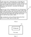
- FIG. 5 is a schematic diagram of a data management method for a database cluster according to an embodiment of the present invention.
- data transmission may be directly performed by using a dual port, so as to avoid a problem of a low data transmission speed caused by a case such as network congestion.
- At least one port in the first dual port SSD is a PCIE port; and at least one port in the second dual port SSD is a PCIE port.
- the first node further includes: a start unit, configured to start another database process to operate data that was stored in the first node before the first node crashed, where the another database process is independent of an original database process in the second node.
- a start unit configured to start another database process to operate data that was stored in the first node before the first node crashed, where the another database process is independent of an original database process in the second node.
- the first node further includes: a start unit is configured to start another database process to operate data that was stored in the first node before the first node crashed, where the another database process is independent of an original database process in a third node.
- a start unit is configured to start another database process to operate data that was stored in the first node before the first node crashed, where the another database process is independent of an original database process in a third node.
- This embodiment of the present invention provides a data management system for a database cluster, where the database cluster includes a first dual port SSD, a second dual port SSD, a first node, a second node, and a third node, where the first dual port SSD is connected to the first node and the second node, and the second dual port SSD is connected to the second node and the third node; and the first node writes a transaction log to the first dual port SSD, so that in a case in which the first node crashes, the second node acquires the transaction log from the first dual port SSD, and the second node operates, according to the transaction log, data that was stored in the first node before the first node crashed; or the first node writes a transaction log to the first dual port SSD, so that in a case in which the first node crashes, after the second node acquires the transaction log from the first dual port SSD, the second node sends the transaction log to the third node, and the third node operates data that was stored in the first node before the first node crashed
- FIG. 6 is a flowchart of a data management method for a database cluster according to an embodiment of the present invention.
- a first dual port SSD is connected to a first node and a second node
- a second dual port SSD is connected to the second node and a third node
- the second node is separately connected to the first dual port SSD and the second dual port SSD.
- the method includes: Step 601: The first node writes a transaction log to the first dual port SSD, so that in a case in which the first node crashes, the second node acquires the transaction log from the first dual port SSD, and the second node operates, according to the transaction log, data that was stored in the first node before the first node crashed; or the first node writes a transaction log to the first dual port SSD, so that in a case in which the first node crashes, after the second node acquires the transaction log from the first dual port SSD, the second node sends the transaction log to the third node, and the third node operates data that was stored in the first node before the first node crashed, where the third node, the first node, and the second node being capable of data transmission with each other.
- the method further includes: acquiring, by the first node in a preset period, a transaction log that is after a checkpoint of the first dual port SSD, and archiving, into a shared disk array, the transaction log that is after the checkpoint.
- the method further includes: in a case in which both the first node and the second node are database instances, directly performing, by the first node, data transmission with the second node by using the first dual port SSD.
- At least one port in the first dual port SSD is a PCIE port; and at least one port in the second dual port SSD is a PCIE port.
- the method further includes: starting, by the second node, another database process to operate the data that was stored in the first node before the first node crashed, where the another database process is independent of an original database process in the second node.
- the method further includes: starting, by the third node, another database process to operate the data that was stored in the first node before the first node crashed, where the another database process is independent of an original database process in the third node.
- This embodiment of the present invention provides a data management method for a database cluster, where the database cluster includes a first dual port solid state disk SSD, a second dual port SSD, a first node, a second node, and a third node, where the first dual port SSD is connected to the first node and the second node, and the second dual port SSD is connected to the second node and the third node; and the first node writes a transaction log to the first dual port SSD, so that in a case in which the first node crashes, the second node acquires the transaction log from the first dual port SSD, and the second node operates, according to the transaction log, data that was stored in the first node before the first node crashed; or the first node writes a transaction log to the first dual port SSD, so that in a case in which the first node crashes, after the second node acquires the transaction log from the first dual port SSD, the second node sends the transaction log to the third node, and the third node operates data that was stored in the first node before the first
- FIG. 7 is a structural diagram of apparatuses of a first node according to an embodiment of the present invention. As shown in FIG. 7 ,
- the first node further includes:
- the first node further includes: a transmission unit, configured to: in a case in which both the first node and the second node are database instances, directly perform data transmission with the second node by using the first dual port SSD.
- a transmission unit configured to: in a case in which both the first node and the second node are database instances, directly perform data transmission with the second node by using the first dual port SSD.
- At least one port in the first dual port SSD is a PCIE port; and at least one port in the second dual port SSD is a PCIE port.
- the first node further includes: a start unit, configured to start another database process to operate the data that was stored in the first node before the first node crashed, where the another database process is independent of an original database process in the second node.
- a start unit configured to start another database process to operate the data that was stored in the first node before the first node crashed, where the another database process is independent of an original database process in the second node.
- the first node further includes: a start unit is configured to start another database process to operate the data that was stored in the first node before the first node crashed, where the another database process is independent of an original database process in the third node.
- a start unit is configured to start another database process to operate the data that was stored in the first node before the first node crashed, where the another database process is independent of an original database process in the third node.
- This embodiment of the present invention provides a first node, where the first node writes a transaction log to a first dual port SSD, so that in a case in which the first node crashes, a second node acquires the transaction log from the first dual port SSD, and the second node operates, according to the transaction log, data that was stored in the first node before the first node crashed; or the first node writes a transaction log to the first dual port SSD, so that in a case in which the first node crashes, after the second node acquires the transaction log from the first dual port SSD, the second node sends the transaction log to a third node, and the third node operates data that was stored in the first node before the first node crashed, where the third node, the first node, and the second node being capable of data transmission with each other, so that when the first node crashes, the second node or the third node can use a dual port SSD to read log information of the crashed node, and after performing recovery, replace the first node to provide a service externally
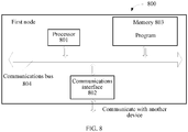
- FIG. 8 is a structural diagram of apparatuses of a first node according to an embodiment of the present invention.
- FIG. 8 shows a first node 800 according to an embodiment of the present invention, and a specific embodiment of the present invention does not limit specific implementation of the first node.
- the first node 800 includes: a processor (processor) 801, a communications interface (Communications Interface) 802, a memory (memory) 803, and a bus 804.
- the processor 801, the communications interface 802, and the memory 803 complete mutual communication by using the bus 804.
- the communications interface 802 is configured to communicate with another device; and the processor 801 is configured to perform a program.
- the program may include program code, and the program code includes a computer operation instruction.
- the processor 801 may be a central processing unit (CPU), or an application-specific integrated circuit Application-Specific Integrated Circuit (ASIC), or is configured as one or more integrated circuits for implementing the embodiments of the present invention.
- CPU central processing unit
- ASIC Application-Specific Integrated Circuit
- the memory 803 is configured to store a program.
- the memory 803 may be a volatile memory (volatile memory), such as a random access memory (RAM), or a non-volatile memory (non-volatile memory), such as a read-only memory (read-only memory, ROM), a flash memory (flash memory), a hard disk drive (hard disk drive, HDD), or a solid state disk SSD).
- volatile memory such as a random access memory (RAM)
- non-volatile memory such as a read-only memory (read-only memory, ROM), a flash memory (flash memory), a hard disk drive (hard disk drive, HDD), or a solid state disk SSD).
- the processor 801 performs the following method according to a program instruction stored in the memory 803:
- the method further includes: acquiring, by the first node in a preset period, a transaction log that is after a checkpoint of the first dual port SSD, and archiving, into a shared disk array, the transaction log that is after the checkpoint.
- the method further includes: in a case in which both the first node and the second node are database instances, directly performing, by the first node, data transmission with the second node by using the first dual port SSD.
- At least one port in the first dual port SSD is a PCIE port; and at least one port in the second dual port SSD is a PCIE port.
- the method further includes: starting, by the second node, another database process to operate the data that was stored in the first node before the first node crashed, where the another database process is independent of an original database process in the second node.
- the method further includes: starting, by the third node, another database process to operate the data that was stored in the first node before the first node crashed, where the another database process is independent of an original database process in the third node.
- This embodiment of the present invention provides a first node, where the first node writes a transaction log to the first dual port SSD, so that in a case in which the first node crashes, the second node acquires the transaction log from the first dual port SSD, and the second node operates, according to the transaction log, data that was stored in the first node before the first node crashed; or the first node writes a transaction log to the first dual port SSD, so that in a case in which the first node crashes, after the second node acquires the transaction log from the first dual port SSD, the second node sends the transaction log to a third node, and the third node operates data that was stored in the first node before the first node crashed, where the third node, the first node, and the second node being capable of data transmission with each other, so that when the first node crashes, the second node or the third node can use a dual port SSD to read log information of the crashed node, and after performing recovery, replace the first node to provide a service externally,
Landscapes
- Engineering & Computer Science (AREA)
- Theoretical Computer Science (AREA)
- Physics & Mathematics (AREA)
- General Engineering & Computer Science (AREA)
- General Physics & Mathematics (AREA)
- Databases & Information Systems (AREA)
- Data Mining & Analysis (AREA)
- Quality & Reliability (AREA)
- Human Computer Interaction (AREA)
- Computer Security & Cryptography (AREA)
- Computing Systems (AREA)
- Information Retrieval, Db Structures And Fs Structures Therefor (AREA)
Claims (11)
- Datenverwaltungsverfahren für einen Datenbank-Cluster, wobei der Datenbank-Cluster eine gemeinsam genutzte Plattenanordnung ("Shared Disk Array"), einen ersten Speicher (101), einen ersten Knoten (103), einen zweiten Knoten (104) und einen dritten Knoten (105) umfasst, wobei der erste Speicher mit dem ersten Knoten und dem zweiten Knoten verbunden ist und das Verfahren umfasst:Schreiben, durch den ersten Knoten, eines Transaktionsprotokolls in den ersten Speicher (101), so dass in einem Fall, in dem der erste Knoten (103) abstürzt, der zweite Knoten (104) das Transaktionsprotokoll aus dem ersten Speicher abruft und gemäß dem Transaktionsprotokoll mit Daten arbeitet, die im ersten Knoten gespeichert waren, bevor der erste Knoten abgestürzt ist; oderSchreiben, durch den ersten Knoten (103), eines Transaktionsprotokolls in den ersten Speicher (101), so dass in einem Fall, in dem der erste Knoten abstürzt, der zweite Knoten (104) das Transaktionsprotokoll aus dem ersten Speicher abruft und das Transaktionsprotokoll an den dritten Knoten (105) sendet und der dritte Knoten mit Daten arbeitet, die im ersten Knoten gespeichert waren, bevor der erste Knoten abgestürzt ist, wobeider dritte Knoten (105), der erste Knoten (103) und der zweite Knoten (104) zur Datenübertragung untereinander in der Lage sind,dadurch gekennzeichnet, dass:der erste Speicher eine erste Festkörperplatte, SSD ("Solid State Disk"), mit zwei Ports ("Dual-Port") ist,der Datenbank-Cluster ferner eine zweite Dual-Port-SSD (102) umfasst,die zweite Dual-Port-SSD mit dem zweiten Knoten und dem dritten Knoten verbunden ist,alle Knoten mit der gemeinsam genutzten Plattenanordnung verbunden sind und die gemeinsam genutzte Plattenanordnung die Daten aller Knoten speichert,sowohl der erste Knoten (103) als auch der zweite Knoten (104) Datenbankinstanzen sind unddie Datenübertragung des Transaktionsprotokolls direkt vom ersten Knoten (103) zum zweiten Knoten (104) unter Verwendung der ersten Dual-Port-SSD (101) erfolgt.
- Verfahren gemäß Anspruch 1, wobei das Verfahren ferner umfasst:
Abrufen, durch den ersten Knoten (103) in einem voreingestellten Zeitraum, eines Transaktionsprotokolls, das nach einem Kontrollpunkt der ersten Dual-Port-SSD (101) liegt, und Archivieren des Transaktionsprotokolls, das nach dem Kontrollpunkt liegt, in der gemeinsam genutzten Plattenanordnung. - Verfahren gemäß Anspruch 1, wobei wenigstens ein Port in der ersten Dual-Port-SSD (101) ein PCIE-Port ist; und wenigstens ein Port in der zweiten Dual-Port-SSD (102) ein PCIE-Port ist.
- Verfahren gemäß einem der Ansprüche 1 bis 3, wobei das Verfahren ferner umfasst:
Starten, durch den zweiten Knoten (104), eines weiteren Datenbankprozesses zum Arbeiten mit den Daten, die im ersten Knoten (103) gespeichert waren, bevor der erste Knoten abgestürzt ist, wobei der weitere Datenbankprozess unabhängig von einem ursprünglichen Datenbankprozess im zweiten Knoten ist. - Verfahren gemäß einem der Ansprüche 1 bis 3, wobei das Verfahren ferner umfasst:
Starten, durch den dritten Knoten (105), eines weiteren Datenbankprozesses zum Arbeiten mit den Daten, die im ersten Knoten (103) gespeichert waren, bevor der erste Knoten abgestürzt ist, wobei der weitere Datenbankprozess unabhängig von einem ursprünglichen Datenbankprozess im dritten Knoten ist. - Datenbank-Cluster, der eine gemeinsam genutzte Plattenanordnung ("Shared Disk Array"), einen ersten Speicher (101), einen ersten Knoten (103), einen zweiten Knoten (104) und einen dritten Knoten (105) umfasst, wobei der erste Speicher mit dem ersten Knoten und dem zweiten Knoten verbunden ist, und wobei der erste Knoten umfasst:eine Schreibeinheit (701), die dafür ausgelegt ist, ein Transaktionsprotokoll in den ersten Speicher (101) zu schreiben, so dass in einem Fall, in dem der erste Knoten (103) abstürzt, der zweite Knoten (104) das Transaktionsprotokoll aus dem ersten Speicher abruft und gemäß dem Transaktionsprotokoll mit Daten arbeitet, die im ersten Knoten gespeichert waren, bevor der erste Knoten abgestürzt ist; oderein Transaktionsprotokoll in den ersten Speicher (101) zu schreiben, so dass in einem Fall, in dem der erste Knoten (103) abstürzt, der zweite Knoten (104) das Transaktionsprotokoll aus dem ersten Speicher abruft und das Transaktionsprotokoll an den dritten Knoten (105) sendet und der dritte Knoten mit Daten arbeitet, die im ersten Knoten gespeichert waren, bevor der erste Knoten abgestürzt ist, wobei der dritte Knoten (105), der erste Knoten (103) und der zweite Knoten (104) zur Datenübertragung untereinander in der Lage sind,dadurch gekennzeichnet, dass:der erste Speicher eine erste Festkörperplatte, SSD ("Solid State Disk"), mit zwei Ports ("Dual-Port") ist,der Datenbank-Cluster ferner eine zweite Dual-Port-SSD (102) umfasst,die zweite Dual-Port-SSD (102) mit dem zweiten Knoten (104) und dem dritten Knoten (105) verbunden ist,wobei alle Knoten mit der gemeinsam genutzten Plattenanordnung verbunden sind und die gemeinsam genutzte Plattenanordnung Daten aller Knoten speichert,sowohl der erste Knoten (103) als auch der zweite Knoten (104) Datenbankinstanzen sind undder erste Knoten (103) ferner eine Übertragungseinheit umfasst, die dafür ausgelegt ist, eine direkte Datenübertragung des Transaktionsprotokolls an den zweiten Knoten (104) unter Verwendung der ersten Dual-Port-SSD (101) durchzuführen.
- Datenbank-Cluster gemäß Anspruch 6, wobei der erste Knoten (103) ferner umfasst:eine Abrufeinheit, die dafür ausgelegt ist, in einem vorgegebenen Zeitraum ein Transaktionsprotokoll abzurufen, das nach einem Kontrollpunkt der ersten Dual-Port-SSD (101) liegt; undeine Archivierungseinheit, die dafür ausgelegt ist, in der gemeinsam genutzten Plattenanordnung das Transaktionsprotokoll, das nach dem Checkpoint liegt, zu archivieren.
- Datenbank-Cluster gemäß Anspruch 6, wobei wenigstens ein Port in der ersten Dual-Port-SSD (101) ein PCIE-Port ist; und wenigstens ein Port in der zweiten Dual-Port-SSD (102) ein PCIE-Port ist.
- Datenbank-Cluster gemäß einem der Ansprüche 6 bis 8, wobei der erste Knoten (103) ferner umfasst:
eine Starteinheit, die dafür ausgelegt ist, einen weiteren Datenbankprozess zum Arbeiten mit den Daten, die im ersten Knoten (103) gespeichert waren, bevor der erste Knoten abgestürzt ist, zu starten, wobei der weitere Datenbankprozess unabhängig von einem ursprünglichen Datenbankprozess im zweiten Knoten (104) ist. - Datenbank-Cluster gemäß einem der Ansprüche 6 bis 8, wobei der erste Knoten (103) ferner umfasst:
eine Starteinheit, die dafür ausgelegt ist, einen weiteren Datenbankprozess zum Arbeiten mit den Daten, die im ersten Knoten (103) gespeichert waren, bevor der erste Knoten abgestürzt ist, zu starten, wobei der weitere Datenbankprozess unabhängig von einem ursprünglichen Datenbankprozess im dritten Knoten (105) ist. - Datenbank-Cluster gemäß einem der Ansprüche 6 bis 10, wobei der zweite Knoten (104) dafür ausgelegt ist: in einem Fall, in dem der erste Knoten (103) abstürzt, das Transaktionsprotokoll von der ersten Dual-Port-SSD (101) abzurufen und gemäß dem Transaktionsprotokoll mit Daten zu arbeiten, die im ersten Knoten gespeichert waren, bevor der erste Knoten abgestürzt ist; oder
in einem Fall, in dem der erste Knoten (103) abstürzt, das Transaktionsprotokoll von der ersten Dual-Port-SSD (101) abzurufen, das Transaktionsprotokoll an den dritten Knoten (105) zu senden, und der dritte Knoten gemäß dem Transaktionsprotokoll mit Daten arbeitet, die im ersten Knoten gespeichert waren, bevor der erste Knoten abgestürzt ist.
Applications Claiming Priority (2)
| Application Number | Priority Date | Filing Date | Title |
|---|---|---|---|
| CN201410242052.XA CN103984768B (zh) | 2014-05-30 | 2014-05-30 | 一种数据库集群管理数据的方法、节点及系统 |
| PCT/CN2014/092140 WO2015180434A1 (zh) | 2014-05-30 | 2014-11-25 | 一种数据库集群管理数据的方法、节点及系统 |
Publications (3)
| Publication Number | Publication Date |
|---|---|
| EP3147797A1 EP3147797A1 (de) | 2017-03-29 |
| EP3147797A4 EP3147797A4 (de) | 2017-04-26 |
| EP3147797B1 true EP3147797B1 (de) | 2021-01-06 |
Family
ID=51276740
Family Applications (1)
| Application Number | Title | Priority Date | Filing Date |
|---|---|---|---|
| EP14893080.3A Active EP3147797B1 (de) | 2014-05-30 | 2014-11-25 | Datenverwaltungsverfahren, knoten und system für einen datenbankcluster |
Country Status (7)
| Country | Link |
|---|---|
| US (2) | US10379977B2 (de) |
| EP (1) | EP3147797B1 (de) |
| JP (1) | JP6457633B2 (de) |
| KR (1) | KR101983208B1 (de) |
| CN (1) | CN103984768B (de) |
| RU (1) | RU2653254C1 (de) |
| WO (1) | WO2015180434A1 (de) |
Families Citing this family (8)
| Publication number | Priority date | Publication date | Assignee | Title |
|---|---|---|---|---|
| CN103984768B (zh) | 2014-05-30 | 2017-09-29 | 华为技术有限公司 | 一种数据库集群管理数据的方法、节点及系统 |
| CN106034137A (zh) * | 2015-03-09 | 2016-10-19 | 阿里巴巴集团控股有限公司 | 用于分布式系统的智能调度方法及分布式服务系统 |
| CN106960060B (zh) * | 2017-04-10 | 2020-07-31 | 聚好看科技股份有限公司 | 一种数据库集群的管理方法及装置 |
| CN109697110B (zh) * | 2017-10-20 | 2023-01-06 | 阿里巴巴集团控股有限公司 | 事务协调处理系统、方法、装置及电子设备 |
| US10754798B1 (en) * | 2019-09-11 | 2020-08-25 | International Business Machines Corporation | Link speed recovery in a data storage system |
| CN111639008B (zh) * | 2020-05-29 | 2023-08-25 | 杭州海康威视系统技术有限公司 | 基于双端口ssd的文件系统状态监测方法、装置及电子设备 |
| KR102428587B1 (ko) | 2022-04-13 | 2022-08-03 | 주식회사 비투엔 | 마이크로 서비스 아키텍처 기반의 트랜잭션 가용성과 성능 보장 처리 장치 및 방법 |
| US11983428B2 (en) | 2022-06-07 | 2024-05-14 | Western Digital Technologies, Inc. | Data migration via data storage device peer channel |
Family Cites Families (30)
| Publication number | Priority date | Publication date | Assignee | Title |
|---|---|---|---|---|
| JPH0991183A (ja) * | 1995-09-27 | 1997-04-04 | Toshiba Corp | データベースリカバリ装置 |
| JP3094888B2 (ja) * | 1996-01-26 | 2000-10-03 | 三菱電機株式会社 | 採番機構、データ整合性確認機構、トランザクション再実行機構及び分散トランザクション処理システム |
| US8041735B1 (en) * | 2002-11-01 | 2011-10-18 | Bluearc Uk Limited | Distributed file system and method |
| US7028218B2 (en) * | 2002-12-02 | 2006-04-11 | Emc Corporation | Redundant multi-processor and logical processor configuration for a file server |
| KR100739674B1 (ko) | 2003-05-01 | 2007-07-13 | 삼성전자주식회사 | 결함 관리 방법, 그 장치 및 그 디스크 |
| JP4141921B2 (ja) * | 2003-08-29 | 2008-08-27 | 富士通株式会社 | ファイル処理方法 |
| US7168001B2 (en) * | 2004-02-06 | 2007-01-23 | Hewlett-Packard Development Company, L.P. | Transaction processing apparatus and method |
| JP4920248B2 (ja) * | 2005-12-02 | 2012-04-18 | 株式会社日立製作所 | サーバの障害回復方法及びデータベースシステム |
| JP2007157150A (ja) * | 2005-12-06 | 2007-06-21 | Samsung Electronics Co Ltd | メモリシステム及びそれを含むメモリ処理方法 |
| US7725446B2 (en) | 2005-12-19 | 2010-05-25 | International Business Machines Corporation | Commitment of transactions in a distributed system |
| JP4856561B2 (ja) * | 2007-01-31 | 2012-01-18 | 日本電信電話株式会社 | ノード制御方法、ノード制御プログラムおよびノード |
| KR101144808B1 (ko) | 2008-09-01 | 2012-05-11 | 엘지전자 주식회사 | 박막형 태양전지 제조방법 및 이를 이용한 박막형 태양전지 |
| US8429134B2 (en) * | 2009-09-08 | 2013-04-23 | Oracle International Corporation | Distributed database recovery |
| US8201020B2 (en) * | 2009-11-12 | 2012-06-12 | International Business Machines Corporation | Method apparatus and system for a redundant and fault tolerant solid state disk |
| US8407403B2 (en) | 2009-12-07 | 2013-03-26 | Microsoft Corporation | Extending SSD lifetime using hybrid storage |
| US8725951B2 (en) * | 2010-04-12 | 2014-05-13 | Sandisk Enterprise Ip Llc | Efficient flash memory-based object store |
| JP2011227834A (ja) * | 2010-04-22 | 2011-11-10 | Sony Corp | 信号制御装置及び信号制御方法 |
| US8666939B2 (en) * | 2010-06-28 | 2014-03-04 | Sandisk Enterprise Ip Llc | Approaches for the replication of write sets |
| US8392378B2 (en) * | 2010-12-09 | 2013-03-05 | International Business Machines Corporation | Efficient backup and restore of virtual input/output server (VIOS) cluster |
| US8589723B2 (en) * | 2010-12-22 | 2013-11-19 | Intel Corporation | Method and apparatus to provide a high availability solid state drive |
| US20120215970A1 (en) * | 2011-02-22 | 2012-08-23 | Serge Shats | Storage Management and Acceleration of Storage Media in Clusters |
| US10949415B2 (en) | 2011-03-31 | 2021-03-16 | International Business Machines Corporation | Logging system using persistent memory |
| JP5514169B2 (ja) * | 2011-08-15 | 2014-06-04 | 株式会社東芝 | 情報処理装置および情報処理方法 |
| CN102521389A (zh) * | 2011-12-23 | 2012-06-27 | 天津神舟通用数据技术有限公司 | 一种混合使用固态硬盘和传统硬盘的postgresql数据库集群系统及其优化方法 |
| JP5867902B2 (ja) * | 2012-03-06 | 2016-02-24 | 日本電気株式会社 | データベースの非同期レプリケーション方式 |
| CN102681952B (zh) * | 2012-05-12 | 2015-02-18 | 北京忆恒创源科技有限公司 | 将数据写入存储设备的方法与存储设备 |
| CN103365987B (zh) * | 2013-07-05 | 2017-04-12 | 北京人大金仓信息技术股份有限公司 | 一种基于共享磁盘架构的集群数据库系统及数据处理方法 |
| CN103729442B (zh) | 2013-12-30 | 2017-11-24 | 华为技术有限公司 | 记录事务日志的方法和数据库引擎 |
| US10169169B1 (en) * | 2014-05-08 | 2019-01-01 | Cisco Technology, Inc. | Highly available transaction logs for storing multi-tenant data sets on shared hybrid storage pools |
| CN103984768B (zh) * | 2014-05-30 | 2017-09-29 | 华为技术有限公司 | 一种数据库集群管理数据的方法、节点及系统 |
-
2014
- 2014-05-30 CN CN201410242052.XA patent/CN103984768B/zh active Active
- 2014-11-25 KR KR1020167036343A patent/KR101983208B1/ko active IP Right Grant
- 2014-11-25 EP EP14893080.3A patent/EP3147797B1/de active Active
- 2014-11-25 WO PCT/CN2014/092140 patent/WO2015180434A1/zh active Application Filing
- 2014-11-25 RU RU2016152176A patent/RU2653254C1/ru active
- 2014-11-25 JP JP2017514759A patent/JP6457633B2/ja active Active
-
2016
- 2016-11-30 US US15/365,728 patent/US10379977B2/en active Active
-
2019
- 2019-06-27 US US16/455,087 patent/US10860447B2/en active Active
Non-Patent Citations (1)
| Title |
|---|
| None * |
Also Published As
| Publication number | Publication date |
|---|---|
| JP6457633B2 (ja) | 2019-01-23 |
| EP3147797A1 (de) | 2017-03-29 |
| RU2653254C1 (ru) | 2018-05-07 |
| CN103984768A (zh) | 2014-08-13 |
| CN103984768B (zh) | 2017-09-29 |
| KR101983208B1 (ko) | 2019-08-28 |
| US10860447B2 (en) | 2020-12-08 |
| KR20170013319A (ko) | 2017-02-06 |
| WO2015180434A1 (zh) | 2015-12-03 |
| JP2017517087A (ja) | 2017-06-22 |
| US10379977B2 (en) | 2019-08-13 |
| US20170083419A1 (en) | 2017-03-23 |
| EP3147797A4 (de) | 2017-04-26 |
| US20190317872A1 (en) | 2019-10-17 |
Similar Documents
| Publication | Publication Date | Title |
|---|---|---|
| EP3147797B1 (de) | Datenverwaltungsverfahren, knoten und system für einen datenbankcluster | |
| EP3179359B1 (de) | Verfahren zum versenden von daten, datenempfangsverfahren und speichervorrichtung | |
| US11397648B2 (en) | Virtual machine recovery method and virtual machine management device | |
| US9372908B2 (en) | Merging an out of synchronization indicator and a change recording indicator in response to a failure in consistency group formation | |
| CN106776130B (zh) | 一种日志恢复方法、存储装置和存储节点 | |
| EP3206128B1 (de) | Datenspeicherverfahren, datenspeichervorrichtung und speichervorrichtung | |
| US9251230B2 (en) | Exchanging locations of an out of synchronization indicator and a change recording indicator via pointers | |
| CN106776147B (zh) | 一种差异数据备份方法和差异数据备份装置 | |
| EP2856317B1 (de) | System und verfahren zur notfallwiederherstellung mehrstufiger anwendungen | |
| US20160085445A1 (en) | Method operating raid system and data storage systems using write command log | |
| US9436554B2 (en) | Information processing apparatus and data repairing method | |
| CN108595287B (zh) | 基于纠删码的数据截断方法及装置 | |
| US11334444B2 (en) | Method, device and computer program product for managing a storage system | |
| US10740189B2 (en) | Distributed storage system | |
| CN104572350B (zh) | 一种元数据处理方法及装置 | |
| JP2017208113A (ja) | データ格納方法、データストレージ装置、及びストレージデバイス | |
| US20150286425A1 (en) | Efficient flashcopy backup target volume allocation | |
| WO2018107460A1 (zh) | 对象复制方法、装置及对象存储设备 |
Legal Events
| Date | Code | Title | Description |
|---|---|---|---|
| STAA | Information on the status of an ep patent application or granted ep patent |
Free format text: STATUS: THE INTERNATIONAL PUBLICATION HAS BEEN MADE |
|
| PUAI | Public reference made under article 153(3) epc to a published international application that has entered the european phase |
Free format text: ORIGINAL CODE: 0009012 |
|
| STAA | Information on the status of an ep patent application or granted ep patent |
Free format text: STATUS: REQUEST FOR EXAMINATION WAS MADE |
|
| 17P | Request for examination filed |
Effective date: 20161208 |
|
| AK | Designated contracting states |
Kind code of ref document: A1 Designated state(s): AL AT BE BG CH CY CZ DE DK EE ES FI FR GB GR HR HU IE IS IT LI LT LU LV MC MK MT NL NO PL PT RO RS SE SI SK SM TR |
|
| AX | Request for extension of the european patent |
Extension state: BA ME |
|
| A4 | Supplementary search report drawn up and despatched |
Effective date: 20170323 |
|
| RIC1 | Information provided on ipc code assigned before grant |
Ipc: G06F 17/30 20060101AFI20170317BHEP Ipc: G06F 11/20 20060101ALI20170317BHEP Ipc: G06F 11/14 20060101ALI20170317BHEP |
|
| DAX | Request for extension of the european patent (deleted) | ||
| STAA | Information on the status of an ep patent application or granted ep patent |
Free format text: STATUS: EXAMINATION IS IN PROGRESS |
|
| 17Q | First examination report despatched |
Effective date: 20190416 |
|
| REG | Reference to a national code |
Ref country code: DE Ref legal event code: R079 Ref document number: 602014074121 Country of ref document: DE Free format text: PREVIOUS MAIN CLASS: G06F0017300000 Ipc: G06F0016000000 |
|
| RIC1 | Information provided on ipc code assigned before grant |
Ipc: G06F 16/00 20190101AFI20200526BHEP Ipc: G06F 11/20 20060101ALI20200526BHEP Ipc: G06F 11/14 20060101ALI20200526BHEP |
|
| GRAP | Despatch of communication of intention to grant a patent |
Free format text: ORIGINAL CODE: EPIDOSNIGR1 |
|
| STAA | Information on the status of an ep patent application or granted ep patent |
Free format text: STATUS: GRANT OF PATENT IS INTENDED |
|
| INTG | Intention to grant announced |
Effective date: 20200724 |
|
| GRAS | Grant fee paid |
Free format text: ORIGINAL CODE: EPIDOSNIGR3 |
|
| GRAA | (expected) grant |
Free format text: ORIGINAL CODE: 0009210 |
|
| STAA | Information on the status of an ep patent application or granted ep patent |
Free format text: STATUS: THE PATENT HAS BEEN GRANTED |
|
| AK | Designated contracting states |
Kind code of ref document: B1 Designated state(s): AL AT BE BG CH CY CZ DE DK EE ES FI FR GB GR HR HU IE IS IT LI LT LU LV MC MK MT NL NO PL PT RO RS SE SI SK SM TR |
|
| REG | Reference to a national code |
Ref country code: GB Ref legal event code: FG4D |
|
| REG | Reference to a national code |
Ref country code: AT Ref legal event code: REF Ref document number: 1353105 Country of ref document: AT Kind code of ref document: T Effective date: 20210115 Ref country code: CH Ref legal event code: EP |
|
| REG | Reference to a national code |
Ref country code: DE Ref legal event code: R096 Ref document number: 602014074121 Country of ref document: DE |
|
| REG | Reference to a national code |
Ref country code: IE Ref legal event code: FG4D |
|
| REG | Reference to a national code |
Ref country code: NL Ref legal event code: MP Effective date: 20210106 |
|
| REG | Reference to a national code |
Ref country code: AT Ref legal event code: MK05 Ref document number: 1353105 Country of ref document: AT Kind code of ref document: T Effective date: 20210106 |
|
| REG | Reference to a national code |
Ref country code: LT Ref legal event code: MG9D |
|
| PG25 | Lapsed in a contracting state [announced via postgrant information from national office to epo] |
Ref country code: GR Free format text: LAPSE BECAUSE OF FAILURE TO SUBMIT A TRANSLATION OF THE DESCRIPTION OR TO PAY THE FEE WITHIN THE PRESCRIBED TIME-LIMIT Effective date: 20210407 Ref country code: HR Free format text: LAPSE BECAUSE OF FAILURE TO SUBMIT A TRANSLATION OF THE DESCRIPTION OR TO PAY THE FEE WITHIN THE PRESCRIBED TIME-LIMIT Effective date: 20210106 Ref country code: FI Free format text: LAPSE BECAUSE OF FAILURE TO SUBMIT A TRANSLATION OF THE DESCRIPTION OR TO PAY THE FEE WITHIN THE PRESCRIBED TIME-LIMIT Effective date: 20210106 Ref country code: LT Free format text: LAPSE BECAUSE OF FAILURE TO SUBMIT A TRANSLATION OF THE DESCRIPTION OR TO PAY THE FEE WITHIN THE PRESCRIBED TIME-LIMIT Effective date: 20210106 Ref country code: PT Free format text: LAPSE BECAUSE OF FAILURE TO SUBMIT A TRANSLATION OF THE DESCRIPTION OR TO PAY THE FEE WITHIN THE PRESCRIBED TIME-LIMIT Effective date: 20210506 Ref country code: BG Free format text: LAPSE BECAUSE OF FAILURE TO SUBMIT A TRANSLATION OF THE DESCRIPTION OR TO PAY THE FEE WITHIN THE PRESCRIBED TIME-LIMIT Effective date: 20210406 Ref country code: NO Free format text: LAPSE BECAUSE OF FAILURE TO SUBMIT A TRANSLATION OF THE DESCRIPTION OR TO PAY THE FEE WITHIN THE PRESCRIBED TIME-LIMIT Effective date: 20210406 Ref country code: NL Free format text: LAPSE BECAUSE OF FAILURE TO SUBMIT A TRANSLATION OF THE DESCRIPTION OR TO PAY THE FEE WITHIN THE PRESCRIBED TIME-LIMIT Effective date: 20210106 |
|
| PG25 | Lapsed in a contracting state [announced via postgrant information from national office to epo] |
Ref country code: PL Free format text: LAPSE BECAUSE OF FAILURE TO SUBMIT A TRANSLATION OF THE DESCRIPTION OR TO PAY THE FEE WITHIN THE PRESCRIBED TIME-LIMIT Effective date: 20210106 Ref country code: LV Free format text: LAPSE BECAUSE OF FAILURE TO SUBMIT A TRANSLATION OF THE DESCRIPTION OR TO PAY THE FEE WITHIN THE PRESCRIBED TIME-LIMIT Effective date: 20210106 Ref country code: RS Free format text: LAPSE BECAUSE OF FAILURE TO SUBMIT A TRANSLATION OF THE DESCRIPTION OR TO PAY THE FEE WITHIN THE PRESCRIBED TIME-LIMIT Effective date: 20210106 Ref country code: AT Free format text: LAPSE BECAUSE OF FAILURE TO SUBMIT A TRANSLATION OF THE DESCRIPTION OR TO PAY THE FEE WITHIN THE PRESCRIBED TIME-LIMIT Effective date: 20210106 Ref country code: SE Free format text: LAPSE BECAUSE OF FAILURE TO SUBMIT A TRANSLATION OF THE DESCRIPTION OR TO PAY THE FEE WITHIN THE PRESCRIBED TIME-LIMIT Effective date: 20210106 |
|
| PG25 | Lapsed in a contracting state [announced via postgrant information from national office to epo] |
Ref country code: IS Free format text: LAPSE BECAUSE OF FAILURE TO SUBMIT A TRANSLATION OF THE DESCRIPTION OR TO PAY THE FEE WITHIN THE PRESCRIBED TIME-LIMIT Effective date: 20210506 |
|
| REG | Reference to a national code |
Ref country code: DE Ref legal event code: R097 Ref document number: 602014074121 Country of ref document: DE |
|
| PG25 | Lapsed in a contracting state [announced via postgrant information from national office to epo] |
Ref country code: EE Free format text: LAPSE BECAUSE OF FAILURE TO SUBMIT A TRANSLATION OF THE DESCRIPTION OR TO PAY THE FEE WITHIN THE PRESCRIBED TIME-LIMIT Effective date: 20210106 Ref country code: CZ Free format text: LAPSE BECAUSE OF FAILURE TO SUBMIT A TRANSLATION OF THE DESCRIPTION OR TO PAY THE FEE WITHIN THE PRESCRIBED TIME-LIMIT Effective date: 20210106 Ref country code: SM Free format text: LAPSE BECAUSE OF FAILURE TO SUBMIT A TRANSLATION OF THE DESCRIPTION OR TO PAY THE FEE WITHIN THE PRESCRIBED TIME-LIMIT Effective date: 20210106 |
|
| PLBE | No opposition filed within time limit |
Free format text: ORIGINAL CODE: 0009261 |
|
| STAA | Information on the status of an ep patent application or granted ep patent |
Free format text: STATUS: NO OPPOSITION FILED WITHIN TIME LIMIT |
|
| PG25 | Lapsed in a contracting state [announced via postgrant information from national office to epo] |
Ref country code: DK Free format text: LAPSE BECAUSE OF FAILURE TO SUBMIT A TRANSLATION OF THE DESCRIPTION OR TO PAY THE FEE WITHIN THE PRESCRIBED TIME-LIMIT Effective date: 20210106 Ref country code: ES Free format text: LAPSE BECAUSE OF FAILURE TO SUBMIT A TRANSLATION OF THE DESCRIPTION OR TO PAY THE FEE WITHIN THE PRESCRIBED TIME-LIMIT Effective date: 20210106 Ref country code: SK Free format text: LAPSE BECAUSE OF FAILURE TO SUBMIT A TRANSLATION OF THE DESCRIPTION OR TO PAY THE FEE WITHIN THE PRESCRIBED TIME-LIMIT Effective date: 20210106 Ref country code: RO Free format text: LAPSE BECAUSE OF FAILURE TO SUBMIT A TRANSLATION OF THE DESCRIPTION OR TO PAY THE FEE WITHIN THE PRESCRIBED TIME-LIMIT Effective date: 20210106 |
|
| 26N | No opposition filed |
Effective date: 20211007 |
|
| PG25 | Lapsed in a contracting state [announced via postgrant information from national office to epo] |
Ref country code: AL Free format text: LAPSE BECAUSE OF FAILURE TO SUBMIT A TRANSLATION OF THE DESCRIPTION OR TO PAY THE FEE WITHIN THE PRESCRIBED TIME-LIMIT Effective date: 20210106 |
|
| PG25 | Lapsed in a contracting state [announced via postgrant information from national office to epo] |
Ref country code: SI Free format text: LAPSE BECAUSE OF FAILURE TO SUBMIT A TRANSLATION OF THE DESCRIPTION OR TO PAY THE FEE WITHIN THE PRESCRIBED TIME-LIMIT Effective date: 20210106 |
|
| PG25 | Lapsed in a contracting state [announced via postgrant information from national office to epo] |
Ref country code: IT Free format text: LAPSE BECAUSE OF FAILURE TO SUBMIT A TRANSLATION OF THE DESCRIPTION OR TO PAY THE FEE WITHIN THE PRESCRIBED TIME-LIMIT Effective date: 20210106 |
|
| PG25 | Lapsed in a contracting state [announced via postgrant information from national office to epo] |
Ref country code: IS Free format text: LAPSE BECAUSE OF FAILURE TO SUBMIT A TRANSLATION OF THE DESCRIPTION OR TO PAY THE FEE WITHIN THE PRESCRIBED TIME-LIMIT Effective date: 20210506 |
|
| PG25 | Lapsed in a contracting state [announced via postgrant information from national office to epo] |
Ref country code: MC Free format text: LAPSE BECAUSE OF FAILURE TO SUBMIT A TRANSLATION OF THE DESCRIPTION OR TO PAY THE FEE WITHIN THE PRESCRIBED TIME-LIMIT Effective date: 20210106 |
|
| REG | Reference to a national code |
Ref country code: CH Ref legal event code: PL |
|
| PG25 | Lapsed in a contracting state [announced via postgrant information from national office to epo] |
Ref country code: LU Free format text: LAPSE BECAUSE OF NON-PAYMENT OF DUE FEES Effective date: 20211125 Ref country code: BE Free format text: LAPSE BECAUSE OF NON-PAYMENT OF DUE FEES Effective date: 20211130 |
|
| REG | Reference to a national code |
Ref country code: BE Ref legal event code: MM Effective date: 20211130 |
|
| PG25 | Lapsed in a contracting state [announced via postgrant information from national office to epo] |
Ref country code: FR Free format text: LAPSE BECAUSE OF NON-PAYMENT OF DUE FEES Effective date: 20211130 |
|
| PG25 | Lapsed in a contracting state [announced via postgrant information from national office to epo] |
Ref country code: HU Free format text: LAPSE BECAUSE OF FAILURE TO SUBMIT A TRANSLATION OF THE DESCRIPTION OR TO PAY THE FEE WITHIN THE PRESCRIBED TIME-LIMIT; INVALID AB INITIO Effective date: 20141125 |
|
| PG25 | Lapsed in a contracting state [announced via postgrant information from national office to epo] |
Ref country code: CY Free format text: LAPSE BECAUSE OF FAILURE TO SUBMIT A TRANSLATION OF THE DESCRIPTION OR TO PAY THE FEE WITHIN THE PRESCRIBED TIME-LIMIT Effective date: 20210106 |
|
| PG25 | Lapsed in a contracting state [announced via postgrant information from national office to epo] |
Ref country code: LI Free format text: LAPSE BECAUSE OF NON-PAYMENT OF DUE FEES Effective date: 20220701 Ref country code: CH Free format text: LAPSE BECAUSE OF NON-PAYMENT OF DUE FEES Effective date: 20220701 |
|
| PGFP | Annual fee paid to national office [announced via postgrant information from national office to epo] |
Ref country code: GB Payment date: 20231006 Year of fee payment: 10 |
|
| PGFP | Annual fee paid to national office [announced via postgrant information from national office to epo] |
Ref country code: IE Payment date: 20231009 Year of fee payment: 10 Ref country code: DE Payment date: 20230929 Year of fee payment: 10 |
|
| PG25 | Lapsed in a contracting state [announced via postgrant information from national office to epo] |
Ref country code: MK Free format text: LAPSE BECAUSE OF FAILURE TO SUBMIT A TRANSLATION OF THE DESCRIPTION OR TO PAY THE FEE WITHIN THE PRESCRIBED TIME-LIMIT Effective date: 20210106 |