EP3147797B1 - Data management method, node and system for database cluster - Google Patents
Data management method, node and system for database cluster Download PDFInfo
- Publication number
- EP3147797B1 EP3147797B1 EP14893080.3A EP14893080A EP3147797B1 EP 3147797 B1 EP3147797 B1 EP 3147797B1 EP 14893080 A EP14893080 A EP 14893080A EP 3147797 B1 EP3147797 B1 EP 3147797B1
- Authority
- EP
- European Patent Office
- Prior art keywords
- node
- transaction log
- dual port
- ssd
- data
- Prior art date
- Legal status (The legal status is an assumption and is not a legal conclusion. Google has not performed a legal analysis and makes no representation as to the accuracy of the status listed.)
- Active
Links
- 238000000034 method Methods 0.000 title claims description 84
- 238000013523 data management Methods 0.000 title claims description 18
- 230000009977 dual effect Effects 0.000 claims description 108
- 230000005540 biological transmission Effects 0.000 claims description 22
- 239000007787 solid Substances 0.000 claims description 8
- 238000011084 recovery Methods 0.000 description 17
- 238000010586 diagram Methods 0.000 description 12
- 238000004891 communication Methods 0.000 description 5
- 230000001360 synchronised effect Effects 0.000 description 1
Images


Classifications
-
- G—PHYSICS
- G06—COMPUTING; CALCULATING OR COUNTING
- G06F—ELECTRIC DIGITAL DATA PROCESSING
- G06F11/00—Error detection; Error correction; Monitoring
- G06F11/07—Responding to the occurrence of a fault, e.g. fault tolerance
- G06F11/14—Error detection or correction of the data by redundancy in operation
- G06F11/1402—Saving, restoring, recovering or retrying
- G06F11/1446—Point-in-time backing up or restoration of persistent data
-
- G—PHYSICS
- G06—COMPUTING; CALCULATING OR COUNTING
- G06F—ELECTRIC DIGITAL DATA PROCESSING
- G06F11/00—Error detection; Error correction; Monitoring
- G06F11/07—Responding to the occurrence of a fault, e.g. fault tolerance
- G06F11/16—Error detection or correction of the data by redundancy in hardware
- G06F11/20—Error detection or correction of the data by redundancy in hardware using active fault-masking, e.g. by switching out faulty elements or by switching in spare elements
- G06F11/202—Error detection or correction of the data by redundancy in hardware using active fault-masking, e.g. by switching out faulty elements or by switching in spare elements where processing functionality is redundant
- G06F11/2023—Failover techniques
-
- G—PHYSICS
- G06—COMPUTING; CALCULATING OR COUNTING
- G06F—ELECTRIC DIGITAL DATA PROCESSING
- G06F16/00—Information retrieval; Database structures therefor; File system structures therefor
- G06F16/20—Information retrieval; Database structures therefor; File system structures therefor of structured data, e.g. relational data
- G06F16/27—Replication, distribution or synchronisation of data between databases or within a distributed database system; Distributed database system architectures therefor
- G06F16/275—Synchronous replication
-
- G—PHYSICS
- G06—COMPUTING; CALCULATING OR COUNTING
- G06F—ELECTRIC DIGITAL DATA PROCESSING
- G06F11/00—Error detection; Error correction; Monitoring
- G06F11/07—Responding to the occurrence of a fault, e.g. fault tolerance
- G06F11/16—Error detection or correction of the data by redundancy in hardware
- G06F11/20—Error detection or correction of the data by redundancy in hardware using active fault-masking, e.g. by switching out faulty elements or by switching in spare elements
- G06F11/2053—Error detection or correction of the data by redundancy in hardware using active fault-masking, e.g. by switching out faulty elements or by switching in spare elements where persistent mass storage functionality or persistent mass storage control functionality is redundant
- G06F11/2094—Redundant storage or storage space
-
- G—PHYSICS
- G06—COMPUTING; CALCULATING OR COUNTING
- G06F—ELECTRIC DIGITAL DATA PROCESSING
- G06F11/00—Error detection; Error correction; Monitoring
- G06F11/07—Responding to the occurrence of a fault, e.g. fault tolerance
- G06F11/16—Error detection or correction of the data by redundancy in hardware
- G06F11/20—Error detection or correction of the data by redundancy in hardware using active fault-masking, e.g. by switching out faulty elements or by switching in spare elements
- G06F11/202—Error detection or correction of the data by redundancy in hardware using active fault-masking, e.g. by switching out faulty elements or by switching in spare elements where processing functionality is redundant
- G06F11/2046—Error detection or correction of the data by redundancy in hardware using active fault-masking, e.g. by switching out faulty elements or by switching in spare elements where processing functionality is redundant where the redundant components share persistent storage
-
- G—PHYSICS
- G06—COMPUTING; CALCULATING OR COUNTING
- G06F—ELECTRIC DIGITAL DATA PROCESSING
- G06F11/00—Error detection; Error correction; Monitoring
- G06F11/07—Responding to the occurrence of a fault, e.g. fault tolerance
- G06F11/16—Error detection or correction of the data by redundancy in hardware
- G06F11/20—Error detection or correction of the data by redundancy in hardware using active fault-masking, e.g. by switching out faulty elements or by switching in spare elements
- G06F11/2053—Error detection or correction of the data by redundancy in hardware using active fault-masking, e.g. by switching out faulty elements or by switching in spare elements where persistent mass storage functionality or persistent mass storage control functionality is redundant
- G06F11/2089—Redundant storage control functionality
- G06F11/2092—Techniques of failing over between control units
-
- G—PHYSICS
- G06—COMPUTING; CALCULATING OR COUNTING
- G06F—ELECTRIC DIGITAL DATA PROCESSING
- G06F16/00—Information retrieval; Database structures therefor; File system structures therefor
-
- G—PHYSICS
- G06—COMPUTING; CALCULATING OR COUNTING
- G06F—ELECTRIC DIGITAL DATA PROCESSING
- G06F16/00—Information retrieval; Database structures therefor; File system structures therefor
- G06F16/10—File systems; File servers
- G06F16/11—File system administration, e.g. details of archiving or snapshots
- G06F16/113—Details of archiving
-
- G—PHYSICS
- G06—COMPUTING; CALCULATING OR COUNTING
- G06F—ELECTRIC DIGITAL DATA PROCESSING
- G06F16/00—Information retrieval; Database structures therefor; File system structures therefor
- G06F16/10—File systems; File servers
- G06F16/13—File access structures, e.g. distributed indices
-
- G—PHYSICS
- G06—COMPUTING; CALCULATING OR COUNTING
- G06F—ELECTRIC DIGITAL DATA PROCESSING
- G06F16/00—Information retrieval; Database structures therefor; File system structures therefor
- G06F16/10—File systems; File servers
- G06F16/17—Details of further file system functions
- G06F16/1734—Details of monitoring file system events, e.g. by the use of hooks, filter drivers, logs
-
- G—PHYSICS
- G06—COMPUTING; CALCULATING OR COUNTING
- G06F—ELECTRIC DIGITAL DATA PROCESSING
- G06F16/00—Information retrieval; Database structures therefor; File system structures therefor
- G06F16/10—File systems; File servers
- G06F16/18—File system types
- G06F16/182—Distributed file systems
-
- G—PHYSICS
- G06—COMPUTING; CALCULATING OR COUNTING
- G06F—ELECTRIC DIGITAL DATA PROCESSING
- G06F16/00—Information retrieval; Database structures therefor; File system structures therefor
- G06F16/10—File systems; File servers
- G06F16/18—File system types
- G06F16/182—Distributed file systems
- G06F16/1824—Distributed file systems implemented using Network-attached Storage [NAS] architecture
- G06F16/1827—Management specifically adapted to NAS
-
- G—PHYSICS
- G06—COMPUTING; CALCULATING OR COUNTING
- G06F—ELECTRIC DIGITAL DATA PROCESSING
- G06F16/00—Information retrieval; Database structures therefor; File system structures therefor
- G06F16/20—Information retrieval; Database structures therefor; File system structures therefor of structured data, e.g. relational data
- G06F16/25—Integrating or interfacing systems involving database management systems
-
- G—PHYSICS
- G06—COMPUTING; CALCULATING OR COUNTING
- G06F—ELECTRIC DIGITAL DATA PROCESSING
- G06F3/00—Input arrangements for transferring data to be processed into a form capable of being handled by the computer; Output arrangements for transferring data from processing unit to output unit, e.g. interface arrangements
- G06F3/06—Digital input from, or digital output to, record carriers, e.g. RAID, emulated record carriers or networked record carriers
- G06F3/0601—Interfaces specially adapted for storage systems
- G06F3/0602—Interfaces specially adapted for storage systems specifically adapted to achieve a particular effect
- G06F3/0614—Improving the reliability of storage systems
- G06F3/0619—Improving the reliability of storage systems in relation to data integrity, e.g. data losses, bit errors
-
- G—PHYSICS
- G06—COMPUTING; CALCULATING OR COUNTING
- G06F—ELECTRIC DIGITAL DATA PROCESSING
- G06F3/00—Input arrangements for transferring data to be processed into a form capable of being handled by the computer; Output arrangements for transferring data from processing unit to output unit, e.g. interface arrangements
- G06F3/06—Digital input from, or digital output to, record carriers, e.g. RAID, emulated record carriers or networked record carriers
- G06F3/0601—Interfaces specially adapted for storage systems
- G06F3/0628—Interfaces specially adapted for storage systems making use of a particular technique
- G06F3/0638—Organizing or formatting or addressing of data
- G06F3/064—Management of blocks
-
- G—PHYSICS
- G06—COMPUTING; CALCULATING OR COUNTING
- G06F—ELECTRIC DIGITAL DATA PROCESSING
- G06F3/00—Input arrangements for transferring data to be processed into a form capable of being handled by the computer; Output arrangements for transferring data from processing unit to output unit, e.g. interface arrangements
- G06F3/06—Digital input from, or digital output to, record carriers, e.g. RAID, emulated record carriers or networked record carriers
- G06F3/0601—Interfaces specially adapted for storage systems
- G06F3/0628—Interfaces specially adapted for storage systems making use of a particular technique
- G06F3/0646—Horizontal data movement in storage systems, i.e. moving data in between storage devices or systems
- G06F3/065—Replication mechanisms
-
- G—PHYSICS
- G06—COMPUTING; CALCULATING OR COUNTING
- G06F—ELECTRIC DIGITAL DATA PROCESSING
- G06F3/00—Input arrangements for transferring data to be processed into a form capable of being handled by the computer; Output arrangements for transferring data from processing unit to output unit, e.g. interface arrangements
- G06F3/06—Digital input from, or digital output to, record carriers, e.g. RAID, emulated record carriers or networked record carriers
- G06F3/0601—Interfaces specially adapted for storage systems
- G06F3/0668—Interfaces specially adapted for storage systems adopting a particular infrastructure
- G06F3/067—Distributed or networked storage systems, e.g. storage area networks [SAN], network attached storage [NAS]
-
- G—PHYSICS
- G06—COMPUTING; CALCULATING OR COUNTING
- G06F—ELECTRIC DIGITAL DATA PROCESSING
- G06F3/00—Input arrangements for transferring data to be processed into a form capable of being handled by the computer; Output arrangements for transferring data from processing unit to output unit, e.g. interface arrangements
- G06F3/06—Digital input from, or digital output to, record carriers, e.g. RAID, emulated record carriers or networked record carriers
- G06F3/0601—Interfaces specially adapted for storage systems
- G06F3/0668—Interfaces specially adapted for storage systems adopting a particular infrastructure
- G06F3/0671—In-line storage system
- G06F3/0683—Plurality of storage devices
- G06F3/0688—Non-volatile semiconductor memory arrays
-
- G—PHYSICS
- G06—COMPUTING; CALCULATING OR COUNTING
- G06F—ELECTRIC DIGITAL DATA PROCESSING
- G06F11/00—Error detection; Error correction; Monitoring
- G06F11/07—Responding to the occurrence of a fault, e.g. fault tolerance
- G06F11/14—Error detection or correction of the data by redundancy in operation
- G06F11/1402—Saving, restoring, recovering or retrying
- G06F11/1471—Saving, restoring, recovering or retrying involving logging of persistent data for recovery
-
- G—PHYSICS
- G06—COMPUTING; CALCULATING OR COUNTING
- G06F—ELECTRIC DIGITAL DATA PROCESSING
- G06F2201/00—Indexing scheme relating to error detection, to error correction, and to monitoring
- G06F2201/80—Database-specific techniques
-
- G—PHYSICS
- G06—COMPUTING; CALCULATING OR COUNTING
- G06F—ELECTRIC DIGITAL DATA PROCESSING
- G06F2201/00—Indexing scheme relating to error detection, to error correction, and to monitoring
- G06F2201/805—Real-time
-
- G—PHYSICS
- G06—COMPUTING; CALCULATING OR COUNTING
- G06F—ELECTRIC DIGITAL DATA PROCESSING
- G06F2201/00—Indexing scheme relating to error detection, to error correction, and to monitoring
- G06F2201/82—Solving problems relating to consistency
-
- G—PHYSICS
- G06—COMPUTING; CALCULATING OR COUNTING
- G06F—ELECTRIC DIGITAL DATA PROCESSING
- G06F2213/00—Indexing scheme relating to interconnection of, or transfer of information or other signals between, memories, input/output devices or central processing units
- G06F2213/0026—PCI express
Definitions
- the present invention relates to the field of databases, and in particular, to a data management method, node, and system for a database cluster.
- All nodes in a database cluster are connected to a shared disk array, and the shared disk array stores data of all the nodes. If a node in the database cluster crashes, data updated in the node cannot be used for a period of time, causing some services to be affected.
- a general solution is to update a log of the node to the shared disk array, and when the node crashes, another node reads the log of the node for performing recovery; if another node cannot read the log of the node, the data in the node cannot be restored until the node is restarted, and subsequently, a service is provided externally; such a process is very time-consuming, affecting services.
- US 2011/0060724 A1 describes database cluster made up of multiple nodes each of which executes one or more database server instances that read data from and write data to a database that is located on shared storage. Each of the instances uses and is associated with a separate redo log which is stored in the shared storage to protect against node failure. If a node crashes, each surviving instance reads the redo log of the failed node from the shared storage and database recovery is divided among a plurality of surviving database server instances in the cluster.
- Embodiments of the present invention provide a data management method, node, and system for a database cluster, so as to solve a problem that a service is affected due to a time-consuming recovery process of a node after the node crashes.
- a data management method for a database cluster is provided according to claim 1
- the method further includes: acquiring, by the first node in a preset period, a transaction log that is after a checkpoint of the first dual port SSD, and archiving, into the shared disk array, the transaction log that is after the checkpoint.
- At least one port in the first dual port SSD is a PCIE port; and at least one port in the second dual port SSD is a PCIE port.
- the method further includes: starting, by the second node, another database process to operate the data that was stored in the first node before the first node crashed, where the another database process is independent of an original database process in the second node.
- the method further includes: starting, by the third node, another database process to operate the data that was stored in the first node before the first node crashed, where the another database process is independent of an original database process in the third node.
- a database cluster is provided according to claim 6.
- the first node further includes:
- At least one port in the first dual port SSD is a PCIE port; and at least one port in the second dual port SSD is a PCIE port.
- the first node further includes: a start unit, configured to start another database process to operate the data that was stored in the first node before the first node crashed, where the another database process is independent of an original database process in the second node.
- the first node further includes: a start unit, configured to start another database process to operate the data that was stored in the first node before the first node crashed, where the another database process is independent of an original database process in the third node.
- the embodiments of the present invention provide a data management method for a database cluster, where the database cluster includes a first dual port solid state disk SSD, a second dual port solid state disk SSD, a first node, a second node, and a third node, where the first dual port SSD is connected to the first node and the second node, and the second dual port SSD is connected to the second node and the third node; and the first node writes a transaction log to the first dual port SSD, so that in a case in which the first node crashes, the second node acquires the transaction log from the first dual port SSD, and the second node operates, according to the transaction log, data that was stored in the first node before the first node crashed; or the first node writes a transaction log to the first dual port SSD, so that in a case in which the first node crashes, after the second node acquires the transaction log from the first dual port SSD, the second node sends the transaction log to the third node, and the third node operates data that was stored in the first no
- FIG. 1 is a structural diagram of a data management system for a database cluster according to an embodiment of the present invention. As shown in FIG. 1 , the system includes:
- the first node 103 further includes:
- FIG. 2 to FIG. 4 are schematic diagrams of structures of data management for a database cluster according to embodiments of the present invention.
- a first node generates a transaction log, which is written to an SSD by a background log writing process; the first node regularly reads, from the SSD, a log that is after a checkpoint, and a log archiving process of the first node archives, into a shared disk array, the log that is after the checkpoint; and after recovering by reading the log of the first node by using a first dual port SSD, a second node replaces the first node to work.
- the second node reads the log of the first node from the first dual port SSD, the second node starts a new database process for performing recovery, and after performing recovery, the second node externally provides a service, and the second node reads the log of the first node by using the first dual port SSD, and transmits the log to another node for performing recovery.
- the second node reads the log of the first node from the SSD, the second node transmits the log to a third node, and after acquiring data of the first node and after performing a recovery operation, the third node externally provides a service.
- the first node further includes: a transmission unit, configured to: in a case in which both the first node and the second node are database instances, directly perform data transmission with the second node by using the first dual port SSD.
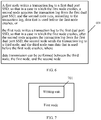
- FIG. 5 is a schematic diagram of a data management method for a database cluster according to an embodiment of the present invention.
- data transmission may be directly performed by using a dual port, so as to avoid a problem of a low data transmission speed caused by a case such as network congestion.
- At least one port in the first dual port SSD is a PCIE port; and at least one port in the second dual port SSD is a PCIE port.
- the first node further includes: a start unit, configured to start another database process to operate data that was stored in the first node before the first node crashed, where the another database process is independent of an original database process in the second node.
- a start unit configured to start another database process to operate data that was stored in the first node before the first node crashed, where the another database process is independent of an original database process in the second node.
- the first node further includes: a start unit is configured to start another database process to operate data that was stored in the first node before the first node crashed, where the another database process is independent of an original database process in a third node.
- a start unit is configured to start another database process to operate data that was stored in the first node before the first node crashed, where the another database process is independent of an original database process in a third node.
- This embodiment of the present invention provides a data management system for a database cluster, where the database cluster includes a first dual port SSD, a second dual port SSD, a first node, a second node, and a third node, where the first dual port SSD is connected to the first node and the second node, and the second dual port SSD is connected to the second node and the third node; and the first node writes a transaction log to the first dual port SSD, so that in a case in which the first node crashes, the second node acquires the transaction log from the first dual port SSD, and the second node operates, according to the transaction log, data that was stored in the first node before the first node crashed; or the first node writes a transaction log to the first dual port SSD, so that in a case in which the first node crashes, after the second node acquires the transaction log from the first dual port SSD, the second node sends the transaction log to the third node, and the third node operates data that was stored in the first node before the first node crashed
- FIG. 6 is a flowchart of a data management method for a database cluster according to an embodiment of the present invention.
- a first dual port SSD is connected to a first node and a second node
- a second dual port SSD is connected to the second node and a third node
- the second node is separately connected to the first dual port SSD and the second dual port SSD.
- the method includes: Step 601: The first node writes a transaction log to the first dual port SSD, so that in a case in which the first node crashes, the second node acquires the transaction log from the first dual port SSD, and the second node operates, according to the transaction log, data that was stored in the first node before the first node crashed; or the first node writes a transaction log to the first dual port SSD, so that in a case in which the first node crashes, after the second node acquires the transaction log from the first dual port SSD, the second node sends the transaction log to the third node, and the third node operates data that was stored in the first node before the first node crashed, where the third node, the first node, and the second node being capable of data transmission with each other.
- the method further includes: acquiring, by the first node in a preset period, a transaction log that is after a checkpoint of the first dual port SSD, and archiving, into a shared disk array, the transaction log that is after the checkpoint.
- the method further includes: in a case in which both the first node and the second node are database instances, directly performing, by the first node, data transmission with the second node by using the first dual port SSD.
- At least one port in the first dual port SSD is a PCIE port; and at least one port in the second dual port SSD is a PCIE port.
- the method further includes: starting, by the second node, another database process to operate the data that was stored in the first node before the first node crashed, where the another database process is independent of an original database process in the second node.
- the method further includes: starting, by the third node, another database process to operate the data that was stored in the first node before the first node crashed, where the another database process is independent of an original database process in the third node.
- This embodiment of the present invention provides a data management method for a database cluster, where the database cluster includes a first dual port solid state disk SSD, a second dual port SSD, a first node, a second node, and a third node, where the first dual port SSD is connected to the first node and the second node, and the second dual port SSD is connected to the second node and the third node; and the first node writes a transaction log to the first dual port SSD, so that in a case in which the first node crashes, the second node acquires the transaction log from the first dual port SSD, and the second node operates, according to the transaction log, data that was stored in the first node before the first node crashed; or the first node writes a transaction log to the first dual port SSD, so that in a case in which the first node crashes, after the second node acquires the transaction log from the first dual port SSD, the second node sends the transaction log to the third node, and the third node operates data that was stored in the first node before the first
- FIG. 7 is a structural diagram of apparatuses of a first node according to an embodiment of the present invention. As shown in FIG. 7 ,
- the first node further includes:
- the first node further includes: a transmission unit, configured to: in a case in which both the first node and the second node are database instances, directly perform data transmission with the second node by using the first dual port SSD.
- a transmission unit configured to: in a case in which both the first node and the second node are database instances, directly perform data transmission with the second node by using the first dual port SSD.
- At least one port in the first dual port SSD is a PCIE port; and at least one port in the second dual port SSD is a PCIE port.
- the first node further includes: a start unit, configured to start another database process to operate the data that was stored in the first node before the first node crashed, where the another database process is independent of an original database process in the second node.
- a start unit configured to start another database process to operate the data that was stored in the first node before the first node crashed, where the another database process is independent of an original database process in the second node.
- the first node further includes: a start unit is configured to start another database process to operate the data that was stored in the first node before the first node crashed, where the another database process is independent of an original database process in the third node.
- a start unit is configured to start another database process to operate the data that was stored in the first node before the first node crashed, where the another database process is independent of an original database process in the third node.
- This embodiment of the present invention provides a first node, where the first node writes a transaction log to a first dual port SSD, so that in a case in which the first node crashes, a second node acquires the transaction log from the first dual port SSD, and the second node operates, according to the transaction log, data that was stored in the first node before the first node crashed; or the first node writes a transaction log to the first dual port SSD, so that in a case in which the first node crashes, after the second node acquires the transaction log from the first dual port SSD, the second node sends the transaction log to a third node, and the third node operates data that was stored in the first node before the first node crashed, where the third node, the first node, and the second node being capable of data transmission with each other, so that when the first node crashes, the second node or the third node can use a dual port SSD to read log information of the crashed node, and after performing recovery, replace the first node to provide a service externally
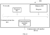
- FIG. 8 is a structural diagram of apparatuses of a first node according to an embodiment of the present invention.
- FIG. 8 shows a first node 800 according to an embodiment of the present invention, and a specific embodiment of the present invention does not limit specific implementation of the first node.
- the first node 800 includes: a processor (processor) 801, a communications interface (Communications Interface) 802, a memory (memory) 803, and a bus 804.
- the processor 801, the communications interface 802, and the memory 803 complete mutual communication by using the bus 804.
- the communications interface 802 is configured to communicate with another device; and the processor 801 is configured to perform a program.
- the program may include program code, and the program code includes a computer operation instruction.
- the processor 801 may be a central processing unit (CPU), or an application-specific integrated circuit Application-Specific Integrated Circuit (ASIC), or is configured as one or more integrated circuits for implementing the embodiments of the present invention.
- CPU central processing unit
- ASIC Application-Specific Integrated Circuit
- the memory 803 is configured to store a program.
- the memory 803 may be a volatile memory (volatile memory), such as a random access memory (RAM), or a non-volatile memory (non-volatile memory), such as a read-only memory (read-only memory, ROM), a flash memory (flash memory), a hard disk drive (hard disk drive, HDD), or a solid state disk SSD).
- volatile memory such as a random access memory (RAM)
- non-volatile memory such as a read-only memory (read-only memory, ROM), a flash memory (flash memory), a hard disk drive (hard disk drive, HDD), or a solid state disk SSD).
- the processor 801 performs the following method according to a program instruction stored in the memory 803:
- the method further includes: acquiring, by the first node in a preset period, a transaction log that is after a checkpoint of the first dual port SSD, and archiving, into a shared disk array, the transaction log that is after the checkpoint.
- the method further includes: in a case in which both the first node and the second node are database instances, directly performing, by the first node, data transmission with the second node by using the first dual port SSD.
- At least one port in the first dual port SSD is a PCIE port; and at least one port in the second dual port SSD is a PCIE port.
- the method further includes: starting, by the second node, another database process to operate the data that was stored in the first node before the first node crashed, where the another database process is independent of an original database process in the second node.
- the method further includes: starting, by the third node, another database process to operate the data that was stored in the first node before the first node crashed, where the another database process is independent of an original database process in the third node.
- This embodiment of the present invention provides a first node, where the first node writes a transaction log to the first dual port SSD, so that in a case in which the first node crashes, the second node acquires the transaction log from the first dual port SSD, and the second node operates, according to the transaction log, data that was stored in the first node before the first node crashed; or the first node writes a transaction log to the first dual port SSD, so that in a case in which the first node crashes, after the second node acquires the transaction log from the first dual port SSD, the second node sends the transaction log to a third node, and the third node operates data that was stored in the first node before the first node crashed, where the third node, the first node, and the second node being capable of data transmission with each other, so that when the first node crashes, the second node or the third node can use a dual port SSD to read log information of the crashed node, and after performing recovery, replace the first node to provide a service externally,
Description
- The present invention relates to the field of databases, and in particular, to a data management method, node, and system for a database cluster.
- All nodes in a database cluster are connected to a shared disk array, and the shared disk array stores data of all the nodes. If a node in the database cluster crashes, data updated in the node cannot be used for a period of time, causing some services to be affected. A general solution is to update a log of the node to the shared disk array, and when the node crashes, another node reads the log of the node for performing recovery; if another node cannot read the log of the node, the data in the node cannot be restored until the node is restarted, and subsequently, a service is provided externally; such a process is very time-consuming, affecting services. In addition, when log information is updated to the shared disk array, performance of a cluster system can also be greatly affected due to a large quantity of synchronized logs.
US 2011/0060724 A1 describes database cluster made up of multiple nodes each of which executes one or more database server instances that read data from and write data to a database that is located on shared storage. Each of the instances uses and is associated with a separate redo log which is stored in the shared storage to protect against node failure. If a node crashes, each surviving instance reads the redo log of the failed node from the shared storage and database recovery is divided among a plurality of surviving database server instances in the cluster. - Embodiments of the present invention provide a data management method, node, and system for a database cluster, so as to solve a problem that a service is affected due to a time-consuming recovery process of a node after the node crashes.
- According to a first aspect, a data management method for a database cluster is provided according to claim 1
- In a first possible implementation manner of the first aspect, the method further includes:
acquiring, by the first node in a preset period, a transaction log that is after a checkpoint of the first dual port SSD, and archiving, into the shared disk array, the transaction log that is after the checkpoint. - In a second possible implementation manner of the first aspect, at least one port in the first dual port SSD is a PCIE port; and at least one port in the second dual port SSD is a PCIE port.
- With reference to the first aspect or any one of the first and second possible implementation manner of the first aspect, in a third possible implementation manner of the first aspect, the method further includes:
starting, by the second node, another database process to operate the data that was stored in the first node before the first node crashed, where the another database process is independent of an original database process in the second node. - With reference to the first aspect or any one of the first to third possible implementation manner of the first aspect, in a fifth possible implementation manner of the first aspect, the method further includes:
starting, by the third node, another database process to operate the data that was stored in the first node before the first node crashed, where the another database process is independent of an original database process in the third node. - According to a second aspect, a database cluster is provided according to claim 6.
- In a first possible implementation manner of the second aspect, the first node further includes:
- an acquiring unit, configured to acquire, in a preset period, a transaction log that is after a checkpoint of the first dual port SSD; and
- an archiving unit, configured to archive, into the shared disk array, the transaction log that is after the checkpoint.
- In a second possible implementation manner of the second aspect, at least one port in the first dual port SSD is a PCIE port; and at least one port in the second dual port SSD is a PCIE port.
- With reference to the second aspect or any one of the first and second possible implementation manner of the second aspect, in a third possible implementation manner of the second aspect, the first node further includes:
a start unit, configured to start another database process to operate the data that was stored in the first node before the first node crashed, where the another database process is independent of an original database process in the second node. - With reference to the second aspect or any one of the first and second possible implementation manner of the second aspect, in a fourth possible implementation manner of the second aspect, the first node further includes:
a start unit, configured to start another database process to operate the data that was stored in the first node before the first node crashed, where the another database process is independent of an original database process in the third node. - The embodiments of the present invention provide a data management method for a database cluster, where the database cluster includes a first dual port solid state disk SSD, a second dual port solid state disk SSD, a first node, a second node, and a third node, where the first dual port SSD is connected to the first node and the second node, and the second dual port SSD is connected to the second node and the third node; and the first node writes a transaction log to the first dual port SSD, so that in a case in which the first node crashes, the second node acquires the transaction log from the first dual port SSD, and the second node operates, according to the transaction log, data that was stored in the first node before the first node crashed; or the first node writes a transaction log to the first dual port SSD, so that in a case in which the first node crashes, after the second node acquires the transaction log from the first dual port SSD, the second node sends the transaction log to the third node, and the third node operates data that was stored in the first node before the first node crashed, where data transmission can be performed between the third node, the first node, and the second node, so that when the first node, the second node or the third node can use a dual port SSD to read log information of the crashed node, and after performing recovery, replace the first node to provide a service externally, thereby improving a recovery speed of the cluster, and improving system availability.
- To describe the technical solutions in the embodiments of the present invention more clearly, the following briefly introduces the accompanying drawings required for describing the embodiments. Apparently, the accompanying drawings in the following description show merely some embodiments of the present invention, and a person of ordinary skill in the art may still derive other drawings from these accompanying drawings without creative efforts.
-
FIG. 1 is a structural diagram of a data management system for a database cluster according to an embodiment of the present invention; -
FIG. 2 is a schematic diagram of a structure of data management for a database cluster according to an embodiment of the present invention; -
FIG. 3 is a schematic diagram of a structure of data management for a database cluster according to an embodiment of the present invention; -
FIG. 4 is a schematic diagram of a structure of data management for a database cluster according to an embodiment of the present invention; -
FIG. 5 is a schematic diagram of a data management method for a database cluster according to an embodiment of the present invention; -
FIG. 6 is a flowchart of a data management method for a database cluster according to an embodiment of the present invention; -
FIG. 7 is a structural diagram of apparatuses of a first node according to an embodiment of the present invention; and -
FIG. 8 is a structural diagram of apparatuses of a first node according to an embodiment of the present invention. - The following clearly describes the technical solutions in the embodiments of the present invention with reference to the accompanying drawings in the embodiments of the present invention. Apparently, the described embodiments are merely some rather than all of the embodiments of the present invention.
- Referring to
FIG. 1, FIG. 1 is a structural diagram of a data management system for a database cluster according to an embodiment of the present invention. As shown inFIG. 1 , the system includes: - a first dual port solid state disk (SSD) 101, a second dual port SSD102, a
first node 103, asecond node 104, and athird node 105, where the first dual port SSD 101 is connected to thefirst node 103 and thesecond node 104, the second dual port SSD 102 is connected to thesecond node 104 and thethird node 105, and thesecond node 104 is separately connected to the first dual port SSD101 and the second dual port SSD 102; - the
first node 103 is configured to write a transaction log (transaction log) to the first dual port SSD 101; and - the
second node 104 is configured to: in a case in which thefirst node 103 crashes, acquire the transaction log from the first dual port SSD 101, and operate, according to the transaction log, data that was stored in the first node before thefirst node 103 crashed; or - in a case in which the
first node 103 crashes, acquire the transaction log from the first dual port SSD 101, send the transaction log to thethird node 105, and thethird node 105 operates, according to the transaction log, data that was stored in the first node before thefirst node 103 crashed, where - data transmission can be performed among the
third node 105, thefirst node 103, and thesecond node 104. - The
first node 103 further includes: - an acquiring unit, configured to acquire, in a preset period, a transaction log that is after a checkpoint of the first dual port SSD; and
- an archiving unit, configured to archive, into a shared disk array, the transaction log that is after the checkpoint.
- Specifically, referring to
FIG. 2 to FIG. 4, FIG. 2 to FIG. 4 are schematic diagrams of structures of data management for a database cluster according to embodiments of the present invention. As shown inFIG. 2 , a first node generates a transaction log, which is written to an SSD by a background log writing process; the first node regularly reads, from the SSD, a log that is after a checkpoint, and a log archiving process of the first node archives, into a shared disk array, the log that is after the checkpoint; and after recovering by reading the log of the first node by using a first dual port SSD, a second node replaces the first node to work. - As shown in
FIG. 3 , after the first node crashes, the second node reads the log of the first node from the first dual port SSD, the second node starts a new database process for performing recovery, and after performing recovery, the second node externally provides a service, and the second node reads the log of the first node by using the first dual port SSD, and transmits the log to another node for performing recovery. - As shown in
FIG. 4 , after the first node crashes, the second node reads the log of the first node from the SSD, the second node transmits the log to a third node, and after acquiring data of the first node and after performing a recovery operation, the third node externally provides a service. - The first node further includes:
a transmission unit, configured to: in a case in which both the first node and the second node are database instances, directly perform data transmission with the second node by using the first dual port SSD. - Specifically, as shown in
FIG. 5, FIG. 5 is a schematic diagram of a data management method for a database cluster according to an embodiment of the present invention. - As shown in
FIG. 5 , in a case in which both a first node and a second node are database instances, data transmission may be directly performed by using a dual port, so as to avoid a problem of a low data transmission speed caused by a case such as network congestion. - Optionally, at least one port in the first dual port SSD is a PCIE port; and at least one port in the second dual port SSD is a PCIE port.
- Optionally, the first node further includes:
a start unit, configured to start another database process to operate data that was stored in the first node before the first node crashed, where the another database process is independent of an original database process in the second node. - Optionally, the first node further includes:
a start unit is configured to start another database process to operate data that was stored in the first node before the first node crashed, where the another database process is independent of an original database process in a third node. - This embodiment of the present invention provides a data management system for a database cluster, where the database cluster includes a first dual port SSD, a second dual port SSD, a first node, a second node, and a third node, where the first dual port SSD is connected to the first node and the second node, and the second dual port SSD is connected to the second node and the third node; and the first node writes a transaction log to the first dual port SSD, so that in a case in which the first node crashes, the second node acquires the transaction log from the first dual port SSD, and the second node operates, according to the transaction log, data that was stored in the first node before the first node crashed; or the first node writes a transaction log to the first dual port SSD, so that in a case in which the first node crashes, after the second node acquires the transaction log from the first dual port SSD, the second node sends the transaction log to the third node, and the third node operates data that was stored in the first node before the first node crashed, where the third node, the first node, and the second node being capable of data transmission with each other, so that when the first node crashes, the second node or the third node can use a dual port SSD to read log information of the crashed node, and after performing recovery, replace the first node to provide a service externally, thereby improving a recovery speed of the cluster, and improving system availability.
- Referring to
FIG. 6, FIG. 6 is a flowchart of a data management method for a database cluster according to an embodiment of the present invention. A first dual port SSD is connected to a first node and a second node, a second dual port SSD is connected to the second node and a third node, and the second node is separately connected to the first dual port SSD and the second dual port SSD. The method includes:
Step 601: The first node writes a transaction log to the first dual port SSD, so that in a case in which the first node crashes, the second node acquires the transaction log from the first dual port SSD, and the second node operates, according to the transaction log, data that was stored in the first node before the first node crashed; or
the first node writes a transaction log to the first dual port SSD, so that in a case in which the first node crashes, after the second node acquires the transaction log from the first dual port SSD, the second node sends the transaction log to the third node, and the third node operates data that was stored in the first node before the first node crashed, where
the third node, the first node, and the second node being capable of data transmission with each other. - The method further includes:
acquiring, by the first node in a preset period, a transaction log that is after a checkpoint of the first dual port SSD, and archiving, into a shared disk array, the transaction log that is after the checkpoint. - The method further includes:
in a case in which both the first node and the second node are database instances, directly performing, by the first node, data transmission with the second node by using the first dual port SSD. - At least one port in the first dual port SSD is a PCIE port; and at least one port in the second dual port SSD is a PCIE port.
- For details, refer to the descriptions of
FIG. 2 to FIG. 4 . - The method further includes:
starting, by the second node, another database process to operate the data that was stored in the first node before the first node crashed, where the another database process is independent of an original database process in the second node. - The method further includes:
starting, by the third node, another database process to operate the data that was stored in the first node before the first node crashed, where the another database process is independent of an original database process in the third node. - For details, refer to the description of
FIG. 5 . - This embodiment of the present invention provides a data management method for a database cluster, where the database cluster includes a first dual port solid state disk SSD, a second dual port SSD, a first node, a second node, and a third node, where the first dual port SSD is connected to the first node and the second node, and the second dual port SSD is connected to the second node and the third node; and the first node writes a transaction log to the first dual port SSD, so that in a case in which the first node crashes, the second node acquires the transaction log from the first dual port SSD, and the second node operates, according to the transaction log, data that was stored in the first node before the first node crashed; or the first node writes a transaction log to the first dual port SSD, so that in a case in which the first node crashes, after the second node acquires the transaction log from the first dual port SSD, the second node sends the transaction log to the third node, and the third node operates data that was stored in the first node before the first node crashed, where the third node, the first node, and the second node being capable of data transmission with each other, so that when the first node crashes, the second node or the third node can use a dual port SSD to read log information of the crashed node, and after performing recovery, replace the first node to provide a service externally, thereby improving a recovery speed of the cluster, and improving system availability.
- Referring to
FIG. 7, FIG. 7 is a structural diagram of apparatuses of a first node according to an embodiment of the present invention. As shown inFIG. 7 , - a database cluster includes a first dual port solid state disk SSD, a second dual port SSD, a first node, a second node, and a third node, where the first dual port SSD is connected to the first node and the second node, and the second dual port SSD is connected to the second node and the third node; and the first node includes:
- a
writing unit 701, configured to write a transaction log to the first dual port SSD, so that in a case in which the first node crashes, the second node acquires the transaction log from the first dual port SSD, and the second node operates, according to the transaction log, data that was stored in the first node before the first node crashed; or - write a transaction log to the first dual port SSD, so that in a case in which the first node crashes, after the second node acquires the transaction log from the first dual port SSD, the second node sends the transaction log to the third node, and the third node operates data that was stored in the first node before the first node crashed, where
- the third node, the first node, and the second node being capable of data transmission with each other.
- Optionally, the first node further includes:
- an acquiring unit, configured to acquire, in a preset period, a transaction log that is after a checkpoint of the first dual port SSD; and
- an archiving unit, configured to archive, into a shared disk array, the transaction log that is after the checkpoint.
- Optionally, the first node further includes:
a transmission unit, configured to: in a case in which both the first node and the second node are database instances, directly perform data transmission with the second node by using the first dual port SSD. - At least one port in the first dual port SSD is a PCIE port; and at least one port in the second dual port SSD is a PCIE port.
- Optionally, the first node further includes:
a start unit, configured to start another database process to operate the data that was stored in the first node before the first node crashed, where the another database process is independent of an original database process in the second node. - Optionally, the first node further includes:
a start unit is configured to start another database process to operate the data that was stored in the first node before the first node crashed, where the another database process is independent of an original database process in the third node. - For details, refer to the descriptions of
FIG. 2 to FIG. 5 . - This embodiment of the present invention provides a first node, where the first node writes a transaction log to a first dual port SSD, so that in a case in which the first node crashes, a second node acquires the transaction log from the first dual port SSD, and the second node operates, according to the transaction log, data that was stored in the first node before the first node crashed; or the first node writes a transaction log to the first dual port SSD, so that in a case in which the first node crashes, after the second node acquires the transaction log from the first dual port SSD, the second node sends the transaction log to a third node, and the third node operates data that was stored in the first node before the first node crashed, where the third node, the first node, and the second node being capable of data transmission with each other, so that when the first node crashes, the second node or the third node can use a dual port SSD to read log information of the crashed node, and after performing recovery, replace the first node to provide a service externally, thereby improving a recovery speed of the cluster, and improving system availability.
-
FIG. 8 is a structural diagram of apparatuses of a first node according to an embodiment of the present invention. Referring toFIG. 8, FIG. 8 shows afirst node 800 according to an embodiment of the present invention, and a specific embodiment of the present invention does not limit specific implementation of the first node. Thefirst node 800 includes:
a processor (processor) 801, a communications interface (Communications Interface) 802, a memory (memory) 803, and a bus 804. - The
processor 801, thecommunications interface 802, and thememory 803 complete mutual communication by using the bus 804. - The
communications interface 802 is configured to communicate with another device; and
theprocessor 801 is configured to perform a program. - Specifically, the program may include program code, and the program code includes a computer operation instruction.
- The
processor 801 may be a central processing unit (CPU), or an application-specific integrated circuit Application-Specific Integrated Circuit (ASIC), or is configured as one or more integrated circuits for implementing the embodiments of the present invention. - The
memory 803 is configured to store a program. Thememory 803 may be a volatile memory (volatile memory), such as a random access memory (RAM), or a non-volatile memory (non-volatile memory), such as a read-only memory (read-only memory, ROM), a flash memory (flash memory), a hard disk drive (hard disk drive, HDD), or a solid state disk SSD). Theprocessor 801 performs the following method according to a program instruction stored in the memory 803: - writing, by the first node, a transaction log to a first dual port SSD, so that in a case in which the first node crashes, a second node acquires the transaction log from the first dual port SSD, and the second node operates, according to the transaction log, data that was stored in the first node before the first node crashed; or
- writing, by the first node, a transaction log to a first dual port SSD, so that in a case in which the first node crashes, after a second node acquires the transaction log from the first dual port SSD, the second node sends the transaction log to a third node, and the third node operates data that was stored in the first node before the first node crashed, where
- the third node, the first node, and the second node being capable of data transmission with each other.
- The method further includes:
acquiring, by the first node in a preset period, a transaction log that is after a checkpoint of the first dual port SSD, and archiving, into a shared disk array, the transaction log that is after the checkpoint. - The method further includes:
in a case in which both the first node and the second node are database instances, directly performing, by the first node, data transmission with the second node by using the first dual port SSD. - At least one port in the first dual port SSD is a PCIE port; and at least one port in the second dual port SSD is a PCIE port.
- The method further includes:
starting, by the second node, another database process to operate the data that was stored in the first node before the first node crashed, where the another database process is independent of an original database process in the second node. - The method further includes:
starting, by the third node, another database process to operate the data that was stored in the first node before the first node crashed, where the another database process is independent of an original database process in the third node. - This embodiment of the present invention provides a first node, where the first node writes a transaction log to the first dual port SSD, so that in a case in which the first node crashes, the second node acquires the transaction log from the first dual port SSD, and the second node operates, according to the transaction log, data that was stored in the first node before the first node crashed; or the first node writes a transaction log to the first dual port SSD, so that in a case in which the first node crashes, after the second node acquires the transaction log from the first dual port SSD, the second node sends the transaction log to a third node, and the third node operates data that was stored in the first node before the first node crashed, where the third node, the first node, and the second node being capable of data transmission with each other, so that when the first node crashes, the second node or the third node can use a dual port SSD to read log information of the crashed node, and after performing recovery, replace the first node to provide a service externally, thereby improving a recovery speed of the cluster, and improving system availability.
- The foregoing descriptions are merely exemplary and specific implementation manners of the present invention, but are not intended to limit the protection scope of the present invention. Any variation or replacement readily figured out by a person skilled in the art within the technical scope disclosed in the present invention shall fall within the protection scope of the present invention. Therefore, the protection scope of the present invention shall be subject to the protection scope of the claims.
Claims (11)
- A data management method for a database cluster, wherein the database cluster comprises a shared disk array, a first storage, (101) a first node (103), a second node (104), and a third node (105), wherein the first storage is connected to the first node and the second node, and the method comprises:writing, by the first node, a transaction log to the first storage (101), so that in a case in which the first node crashes (103), the second node (104) acquires the transaction log from the first storage, and operates, according to the transaction log, data that was stored in the first node before the first node crashed; orwriting, by the first node (103), a transaction log to the first storage (101), so that in a case in which the first node crashes, the second node (104) acquires the transaction log from the first storage, and sends the transaction log to the third node (105), and the third node operates data that was stored in the first node before the first node crashed, whereinthe third node (105), the first node (103), and the second node (104) are capable of data transmission with each other,characterized in thatthe first storage is a first dual port solid state disk, SSD,the database cluster further comprises a second dual port SSD (102), the second dual port SSD is connected to the second node and the third node,all of said nodes are connected to the shared disk array and the shared disk array stores data of all of said nodes,both the first node (103) and the second node (104) are database instances, anddata transmission of the transaction log is directly performed from the first node (103) to the second node (104) by using the first dual port SSD (101).
- The method according to claim 1, wherein the method further comprises:
acquiring, by the first node (103) in a preset period, a transaction log that is after a checkpoint of the first dual port SSD (101), and archiving, into the shared disk array, the transaction log that is after the checkpoint. - The method according to claim 1, wherein at least one port in the first dual port SSD (101) is a PCIE port; and at least one port in the second dual port SSD (102) is a PCIE port.
- The method according to any one of claims 1 to 3, wherein the method further comprises:
starting, by the second node (104), another database process to operate the data that was stored in the first node (103) before the first node crashed, wherein the another database process is independent of an original database process in the second node. - The method according to any one of claims 1 to 3, wherein the method further comprises:
starting, by the third node (105), another database process to operate the data that was stored in the first node (103) before the first node crashed, wherein the another database process is independent of an original database process in the third node. - A database cluster comprising a shared disk array, a first storage, (101), a first node (103), a second node (104), and a third node (105), wherein the first storage is connected to the first node and the second node, and wherein the first node comprises:a writing unit (701), configured to write a transaction log to the first storage (101), so that in a case in which the first node crashes (103), the second node (104) acquires the transaction log from the first storage, and operates, according to the transaction log, data that was stored in the first node before the first node crashed; orwrite a transaction log to the first storage (101), so that in a case in which the first node (103) crashes, the second node (104) acquires the transaction log from the first storage, and sends the transaction log to the third node (105), and the third node operates data that was stored in the first node before the first node crashed, whereinthe third node (105), the first node (103), and the second node (104) are capable of data transmission with each other,characterized in thatthe first storage is a first dual port solid state disk, SSD,the database cluster further comprises a second dual port SSD (102),the second dual port SSD (102) is connected to the second node (104) and the third node (105), all of said nodes are connected to the shared disk array and the shared disk array stores data of all of said nodes,both the first node (103) and the second node (104) are database instances, andthe first node (103) further comprises a transmission unit configured to directly perform data transmission of the transaction log to the second node (104) by using the first dual port SSD (101).
- The database cluster according to claim 6, wherein the first node (103) further comprises:an acquiring unit, configured to acquire, in a preset period, a transaction log that is after a checkpoint of the first dual port SSD (101); andan archiving unit, configured to archive, into the shared disk array, the transaction log that is after the checkpoint.
- The database cluster according to claim 6, wherein at least one port in the first dual port SSD (101) is a PCIE port; and at least one port in the second dual port SSD (102) is a PCIE port.
- The database cluster according to any one of claims 6 to 8, wherein the first node further (103) comprises:
a start unit, configured to start another database process to operate the data that was stored in the first node (103) before the first node crashed, wherein the another database process is independent of an original database process in the second node (104). - The database cluster according to any one of claims 6 to 8, wherein the first node (103) further comprises:
a start unit, configured to start another database process to operate the data that was stored in the first node (103) before the first node crashed, wherein the another database process is independent of an original database process in the third node (105). - The database cluster according to any of claims 6 to 10, wherein the second node (104) is configured to: in a case in which the first node (103) crashes, acquire the transaction log from the first dual port SSD (101), and operate, according to the transaction log, data that was stored in the first node before the first node crashed; or
in a case in which the first node (103) crashes, acquire the transaction log from the first dual port SSD (101), send the transaction log to the third node (105), and the third node operates, according to the transaction log, data that was stored in the first node before the first node crashed.
Applications Claiming Priority (2)
| Application Number | Priority Date | Filing Date | Title |
|---|---|---|---|
| CN201410242052.XA CN103984768B (en) | 2014-05-30 | 2014-05-30 | A kind of data-base cluster manages method, node and the system of data |
| PCT/CN2014/092140 WO2015180434A1 (en) | 2014-05-30 | 2014-11-25 | Data management method, node and system for database cluster |
Publications (3)
| Publication Number | Publication Date |
|---|---|
| EP3147797A1 EP3147797A1 (en) | 2017-03-29 |
| EP3147797A4 EP3147797A4 (en) | 2017-04-26 |
| EP3147797B1 true EP3147797B1 (en) | 2021-01-06 |
Family
ID=51276740
Family Applications (1)
| Application Number | Title | Priority Date | Filing Date |
|---|---|---|---|
| EP14893080.3A Active EP3147797B1 (en) | 2014-05-30 | 2014-11-25 | Data management method, node and system for database cluster |
Country Status (7)
| Country | Link |
|---|---|
| US (2) | US10379977B2 (en) |
| EP (1) | EP3147797B1 (en) |
| JP (1) | JP6457633B2 (en) |
| KR (1) | KR101983208B1 (en) |
| CN (1) | CN103984768B (en) |
| RU (1) | RU2653254C1 (en) |
| WO (1) | WO2015180434A1 (en) |
Families Citing this family (7)
| Publication number | Priority date | Publication date | Assignee | Title |
|---|---|---|---|---|
| CN103984768B (en) | 2014-05-30 | 2017-09-29 | 华为技术有限公司 | A kind of data-base cluster manages method, node and the system of data |
| CN106034137A (en) * | 2015-03-09 | 2016-10-19 | 阿里巴巴集团控股有限公司 | Intelligent scheduling method for distributed system, and distributed service system |
| CN106960060B (en) * | 2017-04-10 | 2020-07-31 | 聚好看科技股份有限公司 | Database cluster management method and device |
| CN109697110B (en) * | 2017-10-20 | 2023-01-06 | 阿里巴巴集团控股有限公司 | Transaction coordination processing system, method and device and electronic equipment |
| US10754798B1 (en) * | 2019-09-11 | 2020-08-25 | International Business Machines Corporation | Link speed recovery in a data storage system |
| CN111639008B (en) * | 2020-05-29 | 2023-08-25 | 杭州海康威视系统技术有限公司 | File system state monitoring method and device based on dual-port SSD and electronic equipment |
| KR102428587B1 (en) | 2022-04-13 | 2022-08-03 | 주식회사 비투엔 | Apparatus and method for handling transaction availability and performance guarantee based on micro service architecture |
Family Cites Families (30)
| Publication number | Priority date | Publication date | Assignee | Title |
|---|---|---|---|---|
| JPH0991183A (en) * | 1995-09-27 | 1997-04-04 | Toshiba Corp | Data base recovery device |
| JP3094888B2 (en) * | 1996-01-26 | 2000-10-03 | 三菱電機株式会社 | Numbering mechanism, data consistency confirmation mechanism, transaction re-execution mechanism, and distributed transaction processing system |
| US8041735B1 (en) * | 2002-11-01 | 2011-10-18 | Bluearc Uk Limited | Distributed file system and method |
| US7028218B2 (en) * | 2002-12-02 | 2006-04-11 | Emc Corporation | Redundant multi-processor and logical processor configuration for a file server |
| KR100739674B1 (en) | 2003-05-01 | 2007-07-13 | 삼성전자주식회사 | Apparatus and method for managing defect and a disc thereof |
| JP4141921B2 (en) * | 2003-08-29 | 2008-08-27 | 富士通株式会社 | File processing method |
| US7168001B2 (en) * | 2004-02-06 | 2007-01-23 | Hewlett-Packard Development Company, L.P. | Transaction processing apparatus and method |
| JP4920248B2 (en) * | 2005-12-02 | 2012-04-18 | 株式会社日立製作所 | Server failure recovery method and database system |
| JP2007157150A (en) * | 2005-12-06 | 2007-06-21 | Samsung Electronics Co Ltd | Memory system and memory processing method including the same |
| US7725446B2 (en) | 2005-12-19 | 2010-05-25 | International Business Machines Corporation | Commitment of transactions in a distributed system |
| JP4856561B2 (en) * | 2007-01-31 | 2012-01-18 | 日本電信電話株式会社 | Node control method, node control program, and node |
| KR101144808B1 (en) | 2008-09-01 | 2012-05-11 | 엘지전자 주식회사 | Manufacturing Method For Thin-Film Type Solar Cell And The Same thereof |
| US8429134B2 (en) * | 2009-09-08 | 2013-04-23 | Oracle International Corporation | Distributed database recovery |
| US8201020B2 (en) * | 2009-11-12 | 2012-06-12 | International Business Machines Corporation | Method apparatus and system for a redundant and fault tolerant solid state disk |
| US8407403B2 (en) | 2009-12-07 | 2013-03-26 | Microsoft Corporation | Extending SSD lifetime using hybrid storage |
| US8725951B2 (en) * | 2010-04-12 | 2014-05-13 | Sandisk Enterprise Ip Llc | Efficient flash memory-based object store |
| JP2011227834A (en) | 2010-04-22 | 2011-11-10 | Sony Corp | Signal control device and signal control method |
| US8954385B2 (en) * | 2010-06-28 | 2015-02-10 | Sandisk Enterprise Ip Llc | Efficient recovery of transactional data stores |
| US8392378B2 (en) * | 2010-12-09 | 2013-03-05 | International Business Machines Corporation | Efficient backup and restore of virtual input/output server (VIOS) cluster |
| US8589723B2 (en) * | 2010-12-22 | 2013-11-19 | Intel Corporation | Method and apparatus to provide a high availability solid state drive |
| US20120215970A1 (en) * | 2011-02-22 | 2012-08-23 | Serge Shats | Storage Management and Acceleration of Storage Media in Clusters |
| US10949415B2 (en) | 2011-03-31 | 2021-03-16 | International Business Machines Corporation | Logging system using persistent memory |
| JP5514169B2 (en) * | 2011-08-15 | 2014-06-04 | 株式会社東芝 | Information processing apparatus and information processing method |
| CN102521389A (en) * | 2011-12-23 | 2012-06-27 | 天津神舟通用数据技术有限公司 | Postgresql database cluster system mixedly using solid state drives and hard disk drive and optimizing method thereof |
| JP5867902B2 (en) * | 2012-03-06 | 2016-02-24 | 日本電気株式会社 | Asynchronous database replication method |
| CN102681952B (en) * | 2012-05-12 | 2015-02-18 | 北京忆恒创源科技有限公司 | Method for writing data into memory equipment and memory equipment |
| CN103365987B (en) * | 2013-07-05 | 2017-04-12 | 北京人大金仓信息技术股份有限公司 | Clustered database system and data processing method based on shared-disk framework |
| CN103729442B (en) * | 2013-12-30 | 2017-11-24 | 华为技术有限公司 | Record the method and database engine of transaction journal |
| US10169169B1 (en) * | 2014-05-08 | 2019-01-01 | Cisco Technology, Inc. | Highly available transaction logs for storing multi-tenant data sets on shared hybrid storage pools |
| CN103984768B (en) * | 2014-05-30 | 2017-09-29 | 华为技术有限公司 | A kind of data-base cluster manages method, node and the system of data |
-
2014
- 2014-05-30 CN CN201410242052.XA patent/CN103984768B/en active Active
- 2014-11-25 KR KR1020167036343A patent/KR101983208B1/en active IP Right Grant
- 2014-11-25 WO PCT/CN2014/092140 patent/WO2015180434A1/en active Application Filing
- 2014-11-25 EP EP14893080.3A patent/EP3147797B1/en active Active
- 2014-11-25 RU RU2016152176A patent/RU2653254C1/en active
- 2014-11-25 JP JP2017514759A patent/JP6457633B2/en active Active
-
2016
- 2016-11-30 US US15/365,728 patent/US10379977B2/en active Active
-
2019
- 2019-06-27 US US16/455,087 patent/US10860447B2/en active Active
Non-Patent Citations (1)
| Title |
|---|
| None * |
Also Published As
| Publication number | Publication date |
|---|---|
| RU2653254C1 (en) | 2018-05-07 |
| CN103984768A (en) | 2014-08-13 |
| KR101983208B1 (en) | 2019-08-28 |
| EP3147797A4 (en) | 2017-04-26 |
| KR20170013319A (en) | 2017-02-06 |
| JP6457633B2 (en) | 2019-01-23 |
| US10379977B2 (en) | 2019-08-13 |
| JP2017517087A (en) | 2017-06-22 |
| CN103984768B (en) | 2017-09-29 |
| EP3147797A1 (en) | 2017-03-29 |
| US20190317872A1 (en) | 2019-10-17 |
| US20170083419A1 (en) | 2017-03-23 |
| WO2015180434A1 (en) | 2015-12-03 |
| US10860447B2 (en) | 2020-12-08 |
Similar Documents
| Publication | Publication Date | Title |
|---|---|---|
| EP3147797B1 (en) | Data management method, node and system for database cluster | |
| EP3179359B1 (en) | Data sending method, data receiving method, and storage device | |
| US11397648B2 (en) | Virtual machine recovery method and virtual machine management device | |
| US9372908B2 (en) | Merging an out of synchronization indicator and a change recording indicator in response to a failure in consistency group formation | |
| CN106776130B (en) | Log recovery method, storage device and storage node | |
| EP3206128B1 (en) | Data storage method, data storage apparatus, and storage device | |
| US9251230B2 (en) | Exchanging locations of an out of synchronization indicator and a change recording indicator via pointers | |
| EP2856317B1 (en) | System and method for disaster recovery of multi-tier applications | |
| US20160085445A1 (en) | Method operating raid system and data storage systems using write command log | |
| US9436554B2 (en) | Information processing apparatus and data repairing method | |
| CN108595287B (en) | Data truncation method and device based on erasure codes | |
| US11334444B2 (en) | Method, device and computer program product for managing a storage system | |
| US10740189B2 (en) | Distributed storage system | |
| CN104572350B (en) | A kind of metadata processing method and device | |
| JP2017208113A (en) | Data storage method, data storage apparatus, and storage device | |
| US20150286425A1 (en) | Efficient flashcopy backup target volume allocation | |
| WO2018107460A1 (en) | Object-based copying method and apparatus, and object-based storage device |
Legal Events
| Date | Code | Title | Description |
|---|---|---|---|
| STAA | Information on the status of an ep patent application or granted ep patent |
Free format text: STATUS: THE INTERNATIONAL PUBLICATION HAS BEEN MADE |
|
| PUAI | Public reference made under article 153(3) epc to a published international application that has entered the european phase |
Free format text: ORIGINAL CODE: 0009012 |
|
| STAA | Information on the status of an ep patent application or granted ep patent |
Free format text: STATUS: REQUEST FOR EXAMINATION WAS MADE |
|
| 17P | Request for examination filed |
Effective date: 20161208 |
|
| AK | Designated contracting states |
Kind code of ref document: A1 Designated state(s): AL AT BE BG CH CY CZ DE DK EE ES FI FR GB GR HR HU IE IS IT LI LT LU LV MC MK MT NL NO PL PT RO RS SE SI SK SM TR |
|
| AX | Request for extension of the european patent |
Extension state: BA ME |
|
| A4 | Supplementary search report drawn up and despatched |
Effective date: 20170323 |
|
| RIC1 | Information provided on ipc code assigned before grant |
Ipc: G06F 17/30 20060101AFI20170317BHEP Ipc: G06F 11/20 20060101ALI20170317BHEP Ipc: G06F 11/14 20060101ALI20170317BHEP |
|
| DAX | Request for extension of the european patent (deleted) | ||
| STAA | Information on the status of an ep patent application or granted ep patent |
Free format text: STATUS: EXAMINATION IS IN PROGRESS |
|
| 17Q | First examination report despatched |
Effective date: 20190416 |
|
| REG | Reference to a national code |
Ref country code: DE Ref legal event code: R079 Ref document number: 602014074121 Country of ref document: DE Free format text: PREVIOUS MAIN CLASS: G06F0017300000 Ipc: G06F0016000000 |
|
| RIC1 | Information provided on ipc code assigned before grant |
Ipc: G06F 16/00 20190101AFI20200526BHEP Ipc: G06F 11/20 20060101ALI20200526BHEP Ipc: G06F 11/14 20060101ALI20200526BHEP |
|
| GRAP | Despatch of communication of intention to grant a patent |
Free format text: ORIGINAL CODE: EPIDOSNIGR1 |
|
| STAA | Information on the status of an ep patent application or granted ep patent |
Free format text: STATUS: GRANT OF PATENT IS INTENDED |
|
| INTG | Intention to grant announced |
Effective date: 20200724 |
|
| GRAS | Grant fee paid |
Free format text: ORIGINAL CODE: EPIDOSNIGR3 |
|
| GRAA | (expected) grant |
Free format text: ORIGINAL CODE: 0009210 |
|
| STAA | Information on the status of an ep patent application or granted ep patent |
Free format text: STATUS: THE PATENT HAS BEEN GRANTED |
|
| AK | Designated contracting states |
Kind code of ref document: B1 Designated state(s): AL AT BE BG CH CY CZ DE DK EE ES FI FR GB GR HR HU IE IS IT LI LT LU LV MC MK MT NL NO PL PT RO RS SE SI SK SM TR |
|
| REG | Reference to a national code |
Ref country code: GB Ref legal event code: FG4D |
|
| REG | Reference to a national code |
Ref country code: AT Ref legal event code: REF Ref document number: 1353105 Country of ref document: AT Kind code of ref document: T Effective date: 20210115 Ref country code: CH Ref legal event code: EP |
|
| REG | Reference to a national code |
Ref country code: DE Ref legal event code: R096 Ref document number: 602014074121 Country of ref document: DE |
|
| REG | Reference to a national code |
Ref country code: IE Ref legal event code: FG4D |
|
| REG | Reference to a national code |
Ref country code: NL Ref legal event code: MP Effective date: 20210106 |
|
| REG | Reference to a national code |
Ref country code: AT Ref legal event code: MK05 Ref document number: 1353105 Country of ref document: AT Kind code of ref document: T Effective date: 20210106 |
|
| REG | Reference to a national code |
Ref country code: LT Ref legal event code: MG9D |
|
| PG25 | Lapsed in a contracting state [announced via postgrant information from national office to epo] |
Ref country code: GR Free format text: LAPSE BECAUSE OF FAILURE TO SUBMIT A TRANSLATION OF THE DESCRIPTION OR TO PAY THE FEE WITHIN THE PRESCRIBED TIME-LIMIT Effective date: 20210407 Ref country code: HR Free format text: LAPSE BECAUSE OF FAILURE TO SUBMIT A TRANSLATION OF THE DESCRIPTION OR TO PAY THE FEE WITHIN THE PRESCRIBED TIME-LIMIT Effective date: 20210106 Ref country code: FI Free format text: LAPSE BECAUSE OF FAILURE TO SUBMIT A TRANSLATION OF THE DESCRIPTION OR TO PAY THE FEE WITHIN THE PRESCRIBED TIME-LIMIT Effective date: 20210106 Ref country code: LT Free format text: LAPSE BECAUSE OF FAILURE TO SUBMIT A TRANSLATION OF THE DESCRIPTION OR TO PAY THE FEE WITHIN THE PRESCRIBED TIME-LIMIT Effective date: 20210106 Ref country code: PT Free format text: LAPSE BECAUSE OF FAILURE TO SUBMIT A TRANSLATION OF THE DESCRIPTION OR TO PAY THE FEE WITHIN THE PRESCRIBED TIME-LIMIT Effective date: 20210506 Ref country code: BG Free format text: LAPSE BECAUSE OF FAILURE TO SUBMIT A TRANSLATION OF THE DESCRIPTION OR TO PAY THE FEE WITHIN THE PRESCRIBED TIME-LIMIT Effective date: 20210406 Ref country code: NO Free format text: LAPSE BECAUSE OF FAILURE TO SUBMIT A TRANSLATION OF THE DESCRIPTION OR TO PAY THE FEE WITHIN THE PRESCRIBED TIME-LIMIT Effective date: 20210406 Ref country code: NL Free format text: LAPSE BECAUSE OF FAILURE TO SUBMIT A TRANSLATION OF THE DESCRIPTION OR TO PAY THE FEE WITHIN THE PRESCRIBED TIME-LIMIT Effective date: 20210106 |
|
| PG25 | Lapsed in a contracting state [announced via postgrant information from national office to epo] |
Ref country code: PL Free format text: LAPSE BECAUSE OF FAILURE TO SUBMIT A TRANSLATION OF THE DESCRIPTION OR TO PAY THE FEE WITHIN THE PRESCRIBED TIME-LIMIT Effective date: 20210106 Ref country code: LV Free format text: LAPSE BECAUSE OF FAILURE TO SUBMIT A TRANSLATION OF THE DESCRIPTION OR TO PAY THE FEE WITHIN THE PRESCRIBED TIME-LIMIT Effective date: 20210106 Ref country code: RS Free format text: LAPSE BECAUSE OF FAILURE TO SUBMIT A TRANSLATION OF THE DESCRIPTION OR TO PAY THE FEE WITHIN THE PRESCRIBED TIME-LIMIT Effective date: 20210106 Ref country code: AT Free format text: LAPSE BECAUSE OF FAILURE TO SUBMIT A TRANSLATION OF THE DESCRIPTION OR TO PAY THE FEE WITHIN THE PRESCRIBED TIME-LIMIT Effective date: 20210106 Ref country code: SE Free format text: LAPSE BECAUSE OF FAILURE TO SUBMIT A TRANSLATION OF THE DESCRIPTION OR TO PAY THE FEE WITHIN THE PRESCRIBED TIME-LIMIT Effective date: 20210106 |
|
| PG25 | Lapsed in a contracting state [announced via postgrant information from national office to epo] |
Ref country code: IS Free format text: LAPSE BECAUSE OF FAILURE TO SUBMIT A TRANSLATION OF THE DESCRIPTION OR TO PAY THE FEE WITHIN THE PRESCRIBED TIME-LIMIT Effective date: 20210506 |
|
| REG | Reference to a national code |
Ref country code: DE Ref legal event code: R097 Ref document number: 602014074121 Country of ref document: DE |
|
| PG25 | Lapsed in a contracting state [announced via postgrant information from national office to epo] |
Ref country code: EE Free format text: LAPSE BECAUSE OF FAILURE TO SUBMIT A TRANSLATION OF THE DESCRIPTION OR TO PAY THE FEE WITHIN THE PRESCRIBED TIME-LIMIT Effective date: 20210106 Ref country code: CZ Free format text: LAPSE BECAUSE OF FAILURE TO SUBMIT A TRANSLATION OF THE DESCRIPTION OR TO PAY THE FEE WITHIN THE PRESCRIBED TIME-LIMIT Effective date: 20210106 Ref country code: SM Free format text: LAPSE BECAUSE OF FAILURE TO SUBMIT A TRANSLATION OF THE DESCRIPTION OR TO PAY THE FEE WITHIN THE PRESCRIBED TIME-LIMIT Effective date: 20210106 |
|
| PLBE | No opposition filed within time limit |
Free format text: ORIGINAL CODE: 0009261 |
|
| STAA | Information on the status of an ep patent application or granted ep patent |
Free format text: STATUS: NO OPPOSITION FILED WITHIN TIME LIMIT |
|
| PG25 | Lapsed in a contracting state [announced via postgrant information from national office to epo] |
Ref country code: DK Free format text: LAPSE BECAUSE OF FAILURE TO SUBMIT A TRANSLATION OF THE DESCRIPTION OR TO PAY THE FEE WITHIN THE PRESCRIBED TIME-LIMIT Effective date: 20210106 Ref country code: ES Free format text: LAPSE BECAUSE OF FAILURE TO SUBMIT A TRANSLATION OF THE DESCRIPTION OR TO PAY THE FEE WITHIN THE PRESCRIBED TIME-LIMIT Effective date: 20210106 Ref country code: SK Free format text: LAPSE BECAUSE OF FAILURE TO SUBMIT A TRANSLATION OF THE DESCRIPTION OR TO PAY THE FEE WITHIN THE PRESCRIBED TIME-LIMIT Effective date: 20210106 Ref country code: RO Free format text: LAPSE BECAUSE OF FAILURE TO SUBMIT A TRANSLATION OF THE DESCRIPTION OR TO PAY THE FEE WITHIN THE PRESCRIBED TIME-LIMIT Effective date: 20210106 |
|
| 26N | No opposition filed |
Effective date: 20211007 |
|
| PG25 | Lapsed in a contracting state [announced via postgrant information from national office to epo] |
Ref country code: AL Free format text: LAPSE BECAUSE OF FAILURE TO SUBMIT A TRANSLATION OF THE DESCRIPTION OR TO PAY THE FEE WITHIN THE PRESCRIBED TIME-LIMIT Effective date: 20210106 |
|
| PG25 | Lapsed in a contracting state [announced via postgrant information from national office to epo] |
Ref country code: SI Free format text: LAPSE BECAUSE OF FAILURE TO SUBMIT A TRANSLATION OF THE DESCRIPTION OR TO PAY THE FEE WITHIN THE PRESCRIBED TIME-LIMIT Effective date: 20210106 |
|
| PG25 | Lapsed in a contracting state [announced via postgrant information from national office to epo] |
Ref country code: IT Free format text: LAPSE BECAUSE OF FAILURE TO SUBMIT A TRANSLATION OF THE DESCRIPTION OR TO PAY THE FEE WITHIN THE PRESCRIBED TIME-LIMIT Effective date: 20210106 |
|
| PG25 | Lapsed in a contracting state [announced via postgrant information from national office to epo] |
Ref country code: IS Free format text: LAPSE BECAUSE OF FAILURE TO SUBMIT A TRANSLATION OF THE DESCRIPTION OR TO PAY THE FEE WITHIN THE PRESCRIBED TIME-LIMIT Effective date: 20210506 |
|
| PG25 | Lapsed in a contracting state [announced via postgrant information from national office to epo] |
Ref country code: MC Free format text: LAPSE BECAUSE OF FAILURE TO SUBMIT A TRANSLATION OF THE DESCRIPTION OR TO PAY THE FEE WITHIN THE PRESCRIBED TIME-LIMIT Effective date: 20210106 |
|
| REG | Reference to a national code |
Ref country code: CH Ref legal event code: PL |
|
| PG25 | Lapsed in a contracting state [announced via postgrant information from national office to epo] |
Ref country code: LU Free format text: LAPSE BECAUSE OF NON-PAYMENT OF DUE FEES Effective date: 20211125 Ref country code: BE Free format text: LAPSE BECAUSE OF NON-PAYMENT OF DUE FEES Effective date: 20211130 |
|
| REG | Reference to a national code |
Ref country code: BE Ref legal event code: MM Effective date: 20211130 |
|
| PG25 | Lapsed in a contracting state [announced via postgrant information from national office to epo] |
Ref country code: FR Free format text: LAPSE BECAUSE OF NON-PAYMENT OF DUE FEES Effective date: 20211130 |
|
| PG25 | Lapsed in a contracting state [announced via postgrant information from national office to epo] |
Ref country code: HU Free format text: LAPSE BECAUSE OF FAILURE TO SUBMIT A TRANSLATION OF THE DESCRIPTION OR TO PAY THE FEE WITHIN THE PRESCRIBED TIME-LIMIT; INVALID AB INITIO Effective date: 20141125 |
|
| PG25 | Lapsed in a contracting state [announced via postgrant information from national office to epo] |
Ref country code: CY Free format text: LAPSE BECAUSE OF FAILURE TO SUBMIT A TRANSLATION OF THE DESCRIPTION OR TO PAY THE FEE WITHIN THE PRESCRIBED TIME-LIMIT Effective date: 20210106 |
|
| PG25 | Lapsed in a contracting state [announced via postgrant information from national office to epo] |
Ref country code: LI Free format text: LAPSE BECAUSE OF NON-PAYMENT OF DUE FEES Effective date: 20220701 Ref country code: CH Free format text: LAPSE BECAUSE OF NON-PAYMENT OF DUE FEES Effective date: 20220701 |
|
| PGFP | Annual fee paid to national office [announced via postgrant information from national office to epo] |
Ref country code: GB Payment date: 20231006 Year of fee payment: 10 |
|
| PGFP | Annual fee paid to national office [announced via postgrant information from national office to epo] |
Ref country code: IE Payment date: 20231009 Year of fee payment: 10 Ref country code: DE Payment date: 20230929 Year of fee payment: 10 |