EP3147694A1 - Verfahren zum betreiben eines photoelektrischen sensors und photoelektrischer sensor - Google Patents
Verfahren zum betreiben eines photoelektrischen sensors und photoelektrischer sensor Download PDFInfo
- Publication number
- EP3147694A1 EP3147694A1 EP16189443.1A EP16189443A EP3147694A1 EP 3147694 A1 EP3147694 A1 EP 3147694A1 EP 16189443 A EP16189443 A EP 16189443A EP 3147694 A1 EP3147694 A1 EP 3147694A1
- Authority
- EP
- European Patent Office
- Prior art keywords
- event
- received signal
- time
- determined
- control unit
- Prior art date
- Legal status (The legal status is an assumption and is not a legal conclusion. Google has not performed a legal analysis and makes no representation as to the accuracy of the status listed.)
- Granted
Links
Images



Classifications
-
- G—PHYSICS
- G01—MEASURING; TESTING
- G01V—GEOPHYSICS; GRAVITATIONAL MEASUREMENTS; DETECTING MASSES OR OBJECTS; TAGS
- G01V8/00—Prospecting or detecting by optical means
- G01V8/10—Detecting, e.g. by using light barriers
- G01V8/12—Detecting, e.g. by using light barriers using one transmitter and one receiver
-
- G—PHYSICS
- G01—MEASURING; TESTING
- G01V—GEOPHYSICS; GRAVITATIONAL MEASUREMENTS; DETECTING MASSES OR OBJECTS; TAGS
- G01V8/00—Prospecting or detecting by optical means
- G01V8/10—Detecting, e.g. by using light barriers
- G01V8/20—Detecting, e.g. by using light barriers using multiple transmitters or receivers
Definitions
- the invention relates to a method for operating a photoelectric sensor and a photoelectric sensor according to the preambles of the independent claims.
- Photoelectric sensors also referred to as optoelectronic sensors, are used to detect objects.
- a light beam emitted by a transmitting unit is received in a receiving unit for this purpose and fed to an evaluation as an electrical signal.
- an optoelectronic sensor for detecting objects with a transmitting block for emitting a light signal and a receiving block for receiving the light signal and generating a received signal from the received light signal is known.
- the light signal is modulated with a code sequence, wherein in a correlation unit a correlation signal is formed from the received signal and the code sequence used.
- the correlation unit receives the code sequence.
- optical synchronization of the transmission block and the reception block takes place.
- the switching device has a light source part, a light receiving part, a signal processing part and an auxiliary part for controlling and synchronizing the operation of the light source part and the light receiver part.
- the light receiver part comprises the photoelectric converter, which converts the incident light into an electrical signal.
- the signal processing part is provided with a pulse shaper.
- the object of the invention is to develop a method and a photoelectric sensor, wherein a simple and secure synchronization of the evaluation of a pulsed light beam with the pulses of the transmitted and received light beam is possible.
- the acquisition of measured values of the received signal, ie measuring times, should be synchronized with the received signal.
- a pulsed light beam is emitted by a transmitting unit of the sensor.
- the transmitting unit comprises a laser transmitter which emits red laser light.
- light beams are used in a different visible or non-visible frequency range, for example in the infrared range.
- the light beam is received by a spaced apart from the transmitting unit receiving unit and converted into a received signal.
- the receiving unit includes z. B. a photodiode. Measured values of the received signal are detected by an evaluation device. The acquisition of the measured values is synchronized by the evaluation device with the received signal.
- event times of positive edges and / or negative edges of pulses of the received signal are determined by an edge detector of the evaluation device.
- the determination of at least one edge of the pulses of the received signal in the form of event instants will be used, for example, to determine the beginning and the duration, i. the period to derive an impulse. Possibly. Also, a clock in which the pulses are sent derived.
- a following event time is determined in a time interval by an expected, following event time.
- a subsequent event time for example, a positive edge is expected after a period of the received signal.
- a subsequent event time is therefore recognized as valid only if it is close to the expected transmission frequency.
- the selection of an event time point only in the time interval around the expected subsequent event time point has the advantage that misinformation in the rest of the time is caused by disturbances, e.g. by flashes of light or by short-term coverage, disregarded.
- a synchronization is performed when at least two consecutive event times have been determined.
- the information, period and e.g. Start of the pulses, derived from the received signal are the information, period and e.g. Start of the pulses, derived from the received signal.
- the control unit determines, if appropriate from this information, measurement times for recording the measured values from the event times.
- measurement times for recording the measured values from the event times.
- measurement times are the Example of the period and the beginning of a pulse one or more measuring times in the course of a pulse, such as a measurement time at the time of maximum amplitude, determined.
- a synchronization is carried out already after the determination of at least two consecutive event times. The determination of the measurement times and thus the acquisition of the measured values can begin very quickly.
- the measuring times are derived by the control unit directly from the received signal.
- One or more oscillators and corresponding circuits are not necessary.
- a synchronization with the received signal also has the advantage that neither the transmitter unit of a receiving unit known clock must be specified via a clock line nor a transmitter unit triggering clock must be made known via a clock line of the receiver unit. An additional clock line to the transmitter unit is not necessary with these methods.
- event times are determined without detection of measured values until a first synchronization is performed.
- an output value is specified as the value of the time interval.
- the value is e.g. 30% of the period of a pulse.
- the measured values are acquired in a synchronous operating state of the receiving unit after at least one synchronization at the determined measuring times.
- a value of the time interval is reduced.
- the time interval is shortened. This reduces the influence of interference.
- the control unit determines measurement times corresponding to earlier event times.
- the light beam is emitted by the transmitting unit as pulses modulated in a rectangular shape, wherein the control unit determines from the event times in each case a measuring time for determining a measured value of a maximum amplitude and a measuring time for determining a measured value of a minimum amplitude.
- the differences of the measured values of the maximum and the minimum amplitude are calculated and evaluated.
- a change in the difference points for example, to a monitoring case. For example, when a yarn sheet is being monitored with a photoelectric sensor according to the present invention, a certain change in the difference indicates a short darkening by a broken yarn passing through the monitoring path. This also makes it possible to detect small changes in the light intensity.
- a photoelectric sensor according to the invention is suitable for carrying out the methods according to the invention. It has the described features and advantages of the method accordingly.
- a photoelectric sensor is provided with a transmitting unit for emitting a pulsed light beam, with a receiving unit arranged at a distance from the transmitting unit for receiving the light beam and converting the light beam into a received signal and with an evaluation device for detecting measured values of the received signal and for synchronizing the detection of the measured values provided the received signal.
- the evaluation unit has an edge detector which is designed to determine event times of positive edges and / or negative edges of pulses of the received signal.
- the evaluation device has a control unit which is connected to the edge detector and which is designed to determine, after an event time, a following event time in a time interval around the expected, following event time.
- the control unit is designed to perform a synchronization when at least two consecutive event times have been determined. It is designed to determine measurement times for acquiring the measured values from the event times.
- the transmitting unit is designed to emit the light beam as pulses modulated in a rectangular shape.
- the control unit is designed to determine a measuring time for determining a measured value of a maximum amplitude and a measuring time for determining a measured value of a minimum amplitude of the received signal.
- the evaluation device has an analog-to-digital converter for acquiring the measured values and generating digital measured values.
- the control unit is designed to activate the analog-to-digital converter. It is connected to the analog-to-digital converter to activate and receive the digital readings.
- FIG. 1 shows a plurality of photoelectric sensors according to the invention, which are arranged in dashed lines, area 1 of a group of threads on a textile machine, not shown.
- Each photoelectric sensor comprises a transmitting unit 2 and a receiving unit 3 arranged at a distance from the transmitting unit 2.
- the transmitting unit 2 is designed to emit a pulsed light beam 4.
- the light beam 4 is formed by rectangularly modulated pulses.
- the transmitting unit 2 has a laser transmitter, the red light, z. B. with a wavelength of about 750nm.
- the photoelectric sensors are mounted in the region 1 of the yarn sheet so that a cracked, falling down the thread traverses the light beam 4 at least one sensor.
- the transmission units 2 are connected via a power line 5 to a power source 6.
- the power source 6 provides power, for example, at a voltage of 24V.
- the receiving units 3 are connected via a communication line 7 to a controller 8 of the textile machine.
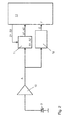
- FIG. 2 shows a block diagram of the receiving unit 2 of a photoelectric sensor, which is adapted to receive the light beam 4 and to evaluate in this example.
- the receiving unit 2 has a receiving device for converting the light beam 4 in a received signal A, the fragmentary in FIG. 4 is shown.
- the receiving device comprises a photodiode 9 for converting the light beam 4 into an electrical signal and an amplifier 10 for amplifying the electrical signal into the received signal A.
- the receiving unit 2 has an evaluation device for detecting measured values A1, A2 of the received signal A and for synchronizing the detection of the measured values A1, A2 with the received signal A.
- the evaluation device comprises an analog-to-digital converter 11, an edge detector 12 and a control unit 13.
- the analog-to-digital converter 11 is designed to detect the measured values A1, A2 of the analog received signal A and to convert them into digital measured values a1, a2.
- a measured value A1 of the maximum amplitude and a measured value A2 of the minimum amplitude of the rectangular pulse are respectively detected ( FIG. 4 ).
- the edge detector 12 is designed to determine event times E of positive edges of the pulses of the received signal A.
- the amplifier 10 is connected to transmit the received signal A to an input of the analog-to-digital converter 11 and to an input of the edge detector 12.
- the control unit 13 is designed to synchronize and evaluate the measured values A1, A2.
- An output of the analog-to-digital converter 11 is connected to the control unit 13 for forwarding digital measured values a1, a2 detected and converted from the analog received signal A.
- the control unit 13 is connected via an activation input for the transmission of measurement times Z1, Z2 to the analog-to-digital converter 11.
- the control unit 13 is designed to activate the analog-to-digital converter 11 at the time of measurement Z1, Z2.
- An output of the edge detector 12 is connected to the control unit 13 for forwarding the event times E.
- the control unit 13 is designed to receive event times E from the edge detector 12 and, if appropriate, to determine them as suitable for synchronization. Upon receipt of a first event time E, a subsequent event time E is determined by the control unit 13 if it is within an interval F of an expected subsequent event time E.
- the control unit 13 is designed to perform a synchronization.
- a synchronization occurs when at least two consecutive event times E have been determined.
- the control unit 13 is designed to evaluate the measured values A1, A2. For example, a difference between the measured values A1, A2 of the maximum and minimum amplitudes is calculated in each case and compared with previous differences. If the difference decreases by a predetermined amount, for example, where a broken thread is suspected, the control unit 13 generates an alarm signal.
- the control unit 13 comprises one or more microprocessors. It comprises timer elements for activating the analog-to-digital converter 11 as well as computing elements for determining e.g. the beginning and the end of the time interval and the measurement times Z1, Z2, as well as for the evaluation of the measured values A1, A2. These elements are designed as circuits and / or program sections.
- a light beam 4 is emitted by the transmitting unit 2 as pulses modulated in a rectangular shape.
- the light beam 4 is received by the reception unit 3 arranged at a distance from the transmission unit 2.
- the receiving device of the receiving unit 3 namely by the photodiode 9 and the amplifier 10
- the light beam 4 is converted into an analog received signal A.
- the evaluation device the measured values A1, A2 of the received signal A recorded and evaluated. Possibly. an alarm signal is generated, which is passed via the communication line 7 to the controller 8 of the textile machine.
- event times E of positive edges of the pulses of the received signal A are determined by the edge detector 12 and sent to the control unit 13.
- a period T of the pulses is derived by the control unit 13 and calculated by means of the period T beginning and end of the time interval F, in which a subsequent event time E is taken into account, as well as the measurement times Z1, Z2.
- the measured values A1, A2 are detected by the analog-to-digital converter 11 and converted into digital measured values a1, a2 for the control unit 13.
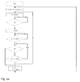
- FIGS. 3a and 3b the progress of a synchronization is further illustrated.
- event times E without the acquisition of measured values A1, A2 are initially determined in an asynchronous operating state of the receiving unit 3 until a synchronization is carried out.
- the period T of the pulses and the time interval F are given by the control unit 13 predetermined start values Ts and Fs.
- a number N of the periods T in a transient operating state is set to zero by the control unit 13.
- a time variable t is set to zero.
- the control unit 13 waits for an event time E of the edge detector 12.
- an event time E is determined by it and passed to the control unit 13.
- a time measurement with the time variable t is started by the control unit 13.
- control unit 13 is a time interval F of start: t > T - F / 2 until the end: t > T + F / 2 calculated.
- control unit 13 sets the time variable t to zero.
- the receiving unit 2 remains in the asynchronous operating state.
- the control unit 13 waits for an event time E of the edge detector 12.
- a positive edge of a following pulse is detected and thus a subsequent event time E is determined, a synchronization is performed.
- the period T receives the value of the time variable t at the following event time E.
- the time variable t is set to zero.
- a new time measurement with the time variable t is started.
- the synchronization is now carried out in a synchronous operating state of the receiving unit 2.
- control unit 13 of the analog-to-digital converter 11 is activated at the time Z1 of the time variable t to detect the measured value A1 of the maximum amplitude.
- the measured value A1 is digitized to the measured value a1 and sent to the control unit 13.
- control unit 13 of the analog-to-digital converter 11 is activated at time Z2 of the time variable t to detect the measured value A2 of the minimum amplitude.
- the measured value A2 is digitized to the measured value a2 and sent to the control unit 13.
- control unit 13 By the control unit 13 is a time interval F of t > T - F / 2 to t > T + F / 2 calculated. If in the time interval F by the edge detector 12, a positive edge of a following pulse is detected and thus a subsequent event time E is determined, the synchronization is carried out further in the synchronous operating state of the receiving unit 2.
- the period T receives the value of the time variable t at the last event time E and the time variable t is set to zero.
- the value of the time interval F is reduced by a value d up to a minimum value Fmin.
- the number N of the periods T in the transient operating state is increased by 1 by the control unit 13. If the number N is less than or equal to a maximum number Nmax, the receiving unit 2 remains in the transient operating state.
- the measured values A1, A2 are recorded as described for the synchronous operating state.
- the edge detector 12 If in the time interval F by the edge detector 12, a positive edge of a following pulse is detected and thus a subsequent event time E is determined, the synchronization is carried out further in the synchronous operating state of the receiving unit 2.
- the receiving unit 2 remains in the transitional operating state.
- the receiving unit 2 is set in the asynchronous operating state by the control unit 13.
- the control unit 13 starts a new synchronization in the asynchronous operating state.
- a synchronization is performed when at least three consecutive event times E have been determined by the control unit 13.
- the evaluation device comprises an edge detector 12 for determining event times E positive and / or negative edges of the pulses of the received signal A. The measuring times for detecting amplitude values are adjusted accordingly.
- the evaluation device or individual parts of the evaluation device for example the control unit 13, are designed as separate devices, which are not included in the receiving unit.
- queries e.g. B. for the determination of event times, performed in a frequency of 10 to 20K Hz.
Landscapes
- Physics & Mathematics (AREA)
- Life Sciences & Earth Sciences (AREA)
- General Life Sciences & Earth Sciences (AREA)
- General Physics & Mathematics (AREA)
- Geophysics (AREA)
- Geophysics And Detection Of Objects (AREA)
- Optical Radar Systems And Details Thereof (AREA)
- Photometry And Measurement Of Optical Pulse Characteristics (AREA)
Abstract
Description
- Die Erfindung betrifft ein Verfahren zum Betreiben eines photoelektrischen Sensors und einen photoelektrischen Sensor gemäß den Oberbegriffen der unabhängigen Ansprüche.
- Photoelektrische Sensoren, auch als optoelektronische Sensoren bezeichnet, werden zur Erfassung von Objekten eingesetzt. Bei sogenannten Einweg-Sensoren wird dazu ein von einer Sendeeinheit ausgesandter Lichtstrahl in einer Empfangseinheit empfangen und als elektrisches Signal einer Auswertung zugeführt.
- Aus der
DE 10 2011 000 857 ist ein optoelektronischer Sensor zur Erfassung von Objekten mit einem Sendeblock zum Aussenden eines Lichtsignals und einem Empfangsblock zum Empfangen des Lichtsignals und Erzeugen eines Empfangssignals aus dem empfangenen Lichtsignal bekannt. Das Lichtsignal wird mit einer Codefolge moduliert, wobei in einer Korrelationseinheit ein Korrelationssignal aus dem Empfangssignal und der verwendeten Codefolge gebildet wird. Die Korrelationseinheit erhält die Codefolge. Alternativ findet eine nicht weiter erläuterte optische Synchronisation des Sendeblocks und des Empfangsblock statt. - In der
DE 311 88 38 C2 ist eine photoelektrische Schalteinrichtung zur Erfassung eines Objektes im Strahlenpfad zwischen einer Lichtquelle und einem photoelektrischen Wandler beschrieben. Die Schalteinrichtung weist einen Lichtquellenteil, einen Lichtempfängerteil, einen Signalverarbeitungsteil und einen Hilfsteil zur Steuerung und Synchronisation der Betriebsweise des Lichtquellenteils und des Lichtempfängerteils auf. Der Lichtempfängerteil umfasst den photoelektrischen Wandler, der das darauf einfallende Licht in ein elektrisches Signal umsetzt. Um Eingabedaten, die auf dem elektrischen Signal basieren, zu verarbeiten, ist der Signalverarbeitungsteil mit einem Impulsformer versehen. Bei einer Verwendung der Schalteinrichtung, bei der die Lichtquelle und der Lichtempfänger getrennt voneinander angeordnet sind, wird der Lichtquellenteil mit einem separaten Oszillator verbunden. Die Frequenz dieses Oszillators ist etwas höher als die eines Oszillators, dessen Ausgangssignal als Taktsignal zur Einspeisung der Eingabedaten verwendet wird. Die Frequenz dieses Oszillators wird auf die Frequenz des separaten Oszillators synchronisiert. - Bei derartigen Schalteinrichtungen führen bereits kurzfristige Störungen des Lichtstrahls, z. B. durch Fremdlicht oder durch eine Abdeckung, zu einer Unterbrechung der Synchronisierung. Eine Synchronisierung ist jedoch beim Einsatz von gepulsten Lichtstrahlen notwendig. Sie ermöglicht die Festlegung von Messzeitpunkten innerhalb der Impulse.
- Aufgabe der Erfindung ist es, ein Verfahren und einen photoelektrischen Sensor zu entwickeln, wobei eine einfache und sichere Synchronisation der Auswertung eines gepulsten Lichtstrahles mit den Impulsen des gesendeten und empfangenen Lichtstrahls ermöglicht wird. Insbesondere soll die Erfassung von Messwerten des Empfangssignals, d.h. Messzeitpunkte, mit dem Empfangssignal synchronisiert werden.
- Diese Aufgabe ist durch die Merkmale der unabhängigen Ansprüche gelöst.
- Bei einem erfindungsgemäßen Verfahren zum Betreiben eines photoelektrischen Sensors wird durch eine Sendeeinheit des Sensors ein gepulster Lichtstrahl ausgesendet.
- In einer Ausführungsform umfasst die Sendeeinheit einen Lasersender, der rotes Laserlicht aussendet. Alternativ werden Lichtstrahlen in einem davon verschiedenen sichtbaren oder nichtsichtbaren Frequenzbereich, zum Beispiel im Infrarotbereich, verwendet.
- Der Lichtstrahl wird durch eine in Abstand zur Sendeeinheit angeordnete Empfangseinheit empfangen und in ein Empfangssignal umgewandelt. Die Empfangseinheit umfasst z. B. eine Photodiode. Messwerte des Empfangssignals werden durch eine Auswertevorrichtung erfasst. Die Erfassung der Messwerte wird durch die Auswertevorrichtung mit dem Empfangssignal synchronisiert.
- Dabei werden durch einen Flankendetektor der Auswertevorrichtung Ereigniszeitpunkte positiver Flanken und/oder negativer Flanken von Impulsen des Empfangssignals ermittelt. Die Ermittlung jeweils mindestens einer Flanke der Impulse des Empfangssignals in Form von Ereigniszeitpunkten wird beispielsweise dazu verwendet werden, den Beginn und die Dauer, d.h. die Periode, eines Impulses abzuleiten. Ggf. wird auch ein Takt, in dem die Impulse gesendet werden, abgeleitet.
- Durch eine Steuereinheit der Auswertevorrichtung, zu der die Ereigniszeitpunkte geleitet werden, wird nach einem Ereigniszeitpunkt ein folgender Ereigniszeitpunkt in einem Zeitintervall um einen erwarteten, folgenden Ereigniszeitpunkt bestimmt.
- Ein folgender Ereigniszeitpunkt zum Beispiel einer positiven Flanke wird nach Ablauf einer Periode des Empfangssignals erwartet. Ein folgender Ereigniszeitpunkt wird daher nur dann als gültig erkannt, wenn er nahe der erwarteten Sendefrequenz liegt.
- Die Auswahl eines Ereigniszeitpunktes lediglich in dem Zeitintervall um den erwarteten, folgenden Ereigniszeitpunkt hat den Vorteil, dass Fehlinformationen in der übrigen Zeit durch Störungen, z.B. durch Lichtblitze oder durch eine kurzfristige Abdeckung, unberücksichtigt bleiben.
- Durch eine Steuereinheit der Auswertevorrichtung wird eine Synchronisation durchgeführt, wenn mindestens zwei aufeinander folgende Ereigniszeitpunkte bestimmt worden sind. Bei einer Synchronisation werden aus mindestens zwei aufeinander folgenden Ereigniszeitpunkten die oben beschriebenen Informationen, Periode und z.B. Beginn der Impulse, aus dem Empfangssignal abgeleitet.
- Durch die Steuereinheit werden, ggf. aus diesen Informationen, Messzeitpunkte zur Erfassung der Messwerte aus den Ereigniszeitpunkten bestimmt. Dabei werden zum Beispiel aus der Periode und dem Beginn eines Impulses ein oder mehrere Messzeitpunkte im Verlauf eines Impulses, wie ein Messzeitpunkt zum Zeitpunkt einer maximalen Amplitude, bestimmt.
- Eine Synchronisation wird bereits nach der Bestimmung von mindestens zwei aufeinander folgenden Ereigniszeitpunkten durchgeführt. Die Bestimmung der Messzeitpunkte und damit die Erfassung der Messwerte können sehr schnell beginnen.
- Die Messzeitpunkte werden durch die Steuereinheit direkt aus dem Empfangssignal abgeleitet. Ein oder mehrere Oszillatoren und entsprechende Schaltungen sind nicht notwendig.
- Eine Synchronisierung mit dem Empfangssignal hat außerdem den Vorteil, dass weder der Sendereinheit ein der Empfangseinheit bekannter Takt über eine Taktleitung vorgegeben werden muss noch ein die Sendeeinheit triggernder Takt über eine Taktleitung der Empfängereinheit bekannt gemacht werden muss. Eine zusätzliche Taktleitung zur Sendereinheit ist auch bei diesen Verfahren nicht notwendig.
- In einer Ausführungsform werden in einem asynchronen Betriebszustand der Auswertevorrichtung Ereigniszeitpunkte ohne Erfassung von Messwerten ermittelt, bis eine erste Synchronisation durchgeführt wird.
- In einer Ausführungsform wird im asynchronen Betriebszustand ein Ausgangswert als Wert des Zeitintervalls vorgegeben. Der Wert beträgt z.B. 30% der Periode eines Impulses.
- In einer Ausführungsform werden in einem synchronen Betriebszustand der Empfangseinheit nach mindestens einer Synchronisation zu den bestimmten Messzeitpunkten die Messwerte erfasst.
- In einer Ausführungsform wird in dem synchronen Betriebszustand nach einer weiteren Synchronisation ein Wert des Zeitintervalls reduziert. Das Zeitintervall wird verkürzt. Dadurch wird der Einfluss von Störungen verringert.
- In einer Ausführungsform wird in einem auf einen synchronen Betriebszustand folgenden Übergangsbetriebszustand der Empfangseinheit, in dem in mindestens einem Zeitintervall um einen erwarteten, folgenden Ereigniszeitpunkt kein Ereigniszeitpunkt ermittelt wird, durch die Steuereinheit Messzeitpunkte entsprechend früherer Ereigniszeitpunkte bestimmt.
- In einer Ausführungsform wird der Lichtstrahl durch die Sendeeinheit als in Rechteckform modulierte Impulse ausgesendet, wobei durch die Steuereinheit aus den Ereigniszeitpunkten jeweils ein Messzeitpunkt zur Ermittlung eines Messwertes einer maximalen Amplitude und ein Messzeitpunkt zur Ermittlung eines Messwertes einer minimalen Amplitude bestimmt werden.
- In einer Ausführungsform werden aus den Messwerten der maximalen und der minimalen Amplitude deren Differenzen berechnet und ausgewertet. Eine Änderung der Differenz weist z.B. auf einen Überwachungsfall hin. Wenn beispielsweise mit einem erfindungsgemäßen photoelektrischen Sensor eine Fadenschar überwacht wird, zeigt eine bestimmte Änderung der Differenz eine kurze Verdunklung durch einen den Überwachungsweg durchlaufenden, gerissenen Faden an. Damit ist auch eine Erfassung von geringen Änderungen der Lichtintensität möglich.
- Ein erfindungsgemäßer photoelektrischer Sensor ist zur Durchführung der erfindungsgemäßen Verfahren geeignet. Er weist die beschriebenen Merkmale und Vorteile der Verfahren entsprechend auf.
- Ein photoelektrischer Sensor ist mit einer Sendeeinheit zur Aussendung eines gepulsten Lichtstrahls, mit einer im Abstand zur Sendeeinheit angeordneten Empfangseinheit zum Empfangen des Lichtstrahls und Umwandeln des Lichtstrahls in ein Empfangssignal und mit einer Auswertevorrichtung zur Erfassung von Messwerten des Empfangssignals und zur Synchronisierung der Erfassung der Messwerte mit dem Empfangssignal versehen.
- Die Auswerteeinheit weist einen Flankendetektor auf, der dazu ausgebildet ist, Ereigniszeitpunkte positiver Flanken und/oder negativer Flanken von Impulsen des Empfangssignals zu ermitteln.
- Die Auswertevorrichtung weist eine Steuereinheit auf, die mit dem Flankendetektor verbunden ist und die dazu ausgebildet ist, nach einem Ereigniszeitpunkt einen folgenden Ereigniszeitpunkt in einem Zeitintervall um den erwarteten, folgenden Ereigniszeitpunkt aus zu bestimmen. Die Steuereinheit ist dazu ausgebildet, eine Synchronisation durch zu führen, wenn mindestens zwei aufeinander folgende Ereigniszeitpunkte bestimmt worden sind. Sie ist dazu ausgebildet, Messzeitpunkte zur Erfassung der Messwerte aus den Ereigniszeitpunkten zu bestimmen.
- In einer Ausführungsform ist die Sendeeinheit dazu ausgebildet, den Lichtstrahl als in Rechteckform modulierte Impulse auszusenden. Die Steuereinheit ist dazu ausgebildet, einen Messzeitpunkt zur Ermittlung eines Messwertes einer maximalen Amplitude und einen Messzeitpunkt zur Ermittlung eines Messwertes einer minimalen Amplitude des Empfangssignals zu bestimmen.
- In einer Ausführungsform weist die Auswertevorrichtung einen Analog-Digital-Wandler zur Erfassung der Messwerte und zur Erzeugung digitaler Messwerte auf. Die Steuereinheit ist dazu ausgebildet, den Analog-Digital-Wandler zu aktivieren. Sie ist zur Aktivierung und zum Empfang der digitalen Messwerte mit dem Analog-Digitalwandler verbunden.
- Die Erfindung wird anhand von in der Zeichnung schematisch dargestellter Beispiele weiter erläutert. Es zeigen:
-
Figur 1 eine schematische Ansicht einer Anordnung mehrerer erfindungsgemäßer photoelektrischer Sensoren; -
Fig. 2 ein Blockdiagramm einer Empfangseinheit eines der photoelektrischen Sensoren; -
Fig. 3a und3b ein Ablaufdiagramm eines erfindungsgemäßen Verfahrens zum Betreiben des photoelektrischen Sensors; und -
Fig. 4 ein Empfangssignal des photoelektrischen Sensors. -
Figur 1 zeigt mehrere erfindungsgemäße photoelektrische Sensoren, die im, gestrichelt eingezeichneten, Bereich 1 einer Fadenschar an einer nicht dargestellten Textilmaschine angeordnet sind. Jeder photoelektrische Sensor umfasst eine Sendeeinheit 2 und eine in einem Abstand zur Sendeeinheit 2 angeordnete Empfangseinheit 3. - Die Sendeeinheit 2 ist dazu ausgebildet, einen gepulsten Lichtstrahl 4 auszusenden. Der Lichtstrahl 4 ist durch in Rechteckform modulierte Impulse gebildet. Die Sendeeinheit 2 weist einen Lasersender auf, der rotes Licht, z. B. mit einer Wellenlänge von etwa 750nm aussendet. Die photoelektrischen Sensoren sind so im Bereich 1 der Fadenschar angebracht, dass ein gerissener, herab fallender Faden den Lichtstrahl 4 mindestens eines Sensors durchquert.
- Die Sendeeinheiten 2 sind über eine Stromleitung 5 an eine Stromquelle 6 angeschlossen. Die Stromquelle 6 stellt Strom zum Beispiel mit einer Spannung von 24 V zur Verfügung. Die Empfangseinheiten 3 sind über eine Kommunikationsleitung 7 mit einer Steuerung 8 der Textilmaschine verbunden.
-
Figur 2 zeigt ein Blockdiagramm der Empfangseinheit 2 eines photoelektrischen Sensors, die dazu ausgebildet ist, den Lichtstrahl 4 zu empfangen und in diesem Beispiel auch auszuwerten. - Die Empfangseinheit 2 weist eine Empfangsvorrichtung zur Umwandlung des Lichtstrahls 4 in ein Empfangssignal A auf, das ausschnittsweise in
Figur 4 dargestellt ist. Die Empfangsvorrichtung umfasst eine Photodiode 9 zur Umwandlung des Lichtstrahls 4 in ein elektrisches Signal und einen Verstärker 10 zur Verstärkung des elektrischen Signals in das Empfangssignal A. - Die Empfangseinheit 2 weist eine Auswertevorrichtung zur Erfassung von Messwerten A1, A2 des Empfangssignals A und zur Synchronisierung der Erfassung der Messwerte A1, A2 mit dem Empfangssignal A auf. Die Auswertevorrichtung umfasst einen Analog-Digital-Wandler 11, einen Flankendetektor 12 und eine Steuereinheit 13.
- Der Analog-Digital-Wandler 11 ist dazu ausgebildet, die Messwerte A1, A2 des analogen Empfangssignal A zu erfassen und in digitale Messwerte a1, a2 umzuwandeln. In diesem Beispiel werden jeweils ein Messwert A1 der maximalen Amplitude und ein Messwert A2 der minimalen Amplitude des Rechteckimpulses erfasst (
Figur 4 ). - Der Flankendetektor 12 ist dazu ausgebildet, Ereigniszeitpunkte E positiver Flanken der Impulse des Empfangssignals A zu ermitteln.
- Der Verstärker 10 ist zur Übermittlung des Empfangssignals A mit einem Eingang des Analog-Digital-Wandlers 11 und mit einem Eingang des Flankendetektors 12 verbunden.
- Die Steuereinheit 13 ist zur Synchronisierung und zur Auswertung der Messwerte A1, A2 ausgebildet.
- Ein Ausgang des Analog-Digital-Wandlers 11 ist zur Weiterleitung von aus dem analogen Empfangssignal A erfassten und umgewandelten, digitalen Messwerten a1, a2 mit der Steuereinheit 13 verbunden.
- Die Steuereinheit 13 ist über einen Aktivierungseingang zur Übermittlung von Messzeitpunkten Z1, Z2 mit dem Analog-Digital-Wandler 11 verbunden. Die Steuereinheit 13 ist dazu ausgebildet, den Analog-Digital-Wandler 11 zu den Messezeitpunkten Z1, Z2 zu aktivieren.
- Ein Ausgang des Flankendetektors 12 ist zur Weiterleitung der Ereigniszeitpunkte E mit der Steuereinheit 13 verbunden.
- Die Steuereinheit 13 ist dazu ausgebildet, Ereigniszeitpunkte E von dem Flankendetektor 12 zu empfangen und ggf. als zur Synchronisation geeignet zu bestimmen. Nach Erhalt eines ersten Ereigniszeitpunktes E wird durch die Steuereinheit 13 ein folgender Ereigniszeitpunkt E bestimmt, wenn er in einem Zeitintervall F um einen erwarteten, folgenden Ereigniszeitpunkt E liegt.
- Die Steuereinheit 13 ist dazu ausgebildet, eine Synchronisation durchzuführen. Eine Synchronisierung erfolgt, wenn mindestens zwei aufeinander folgende Ereigniszeitpunkte E bestimmt worden sind.
- Die Steuereinheit 13 ist zur Auswertung der Messwerte A1, A2 ausgebildet. Es wird beispielsweise jeweils eine Differenz zwischen den Messwerten A1, A2 der maximalen und minimalen Amplitude berechnet und mit vorherigen Differenzen verglichen. Verringert sich die Differenz um einen vorgegebenen Betrag, bei dem zum Beispiel ein gerissener Faden vermutet wird, erzeugt die Steuereinheit 13 ein Alarmsignal.
- Die Steuereinheit 13 umfasst einen oder mehrere Mikroprozessoren. Sie umfasst Zeitgeberelemente zur Aktivierung des Analog-Digital-Wandlers 11 sowie Rechenelemente zur Bestimmung z.B. des Beginns und des Endes des Zeitintervalls und der Messzeitpunkte Z1, Z2, sowie zur Auswertung der Messwerte A1, A2. Diese Elemente sind als Schaltungen und/oder Programmabschnitte ausgebildet.
- In Betrieb eines erfindungsgemäßen photoelektrischen Sensors wird durch die Sendeeinheit 2 ein Lichtstrahl 4 als in Rechteckform modulierte Impulse ausgesendet. Der Lichtstrahl 4 wird durch die in Abstand zur Sendeeinheit 2 angeordnete Empfangseinheit 3 empfangen. Durch die Empfangsvorrichtung der Empfangseinheit 3, nämlich durch die Photodiode 9 und den Verstärker 10, wird der Lichtstrahl 4 in ein analoges Empfangssignal A umgewandelt. Durch die Auswertevorrichtung werden die Messwerte A1, A2 des Empfangssignals A erfasst und ausgewertet. Ggf. wird ein Alarmsignal erzeugt, das über die Kommunikationsleitung 7 zu der Steuerung 8 der Textilmaschine geleitet wird.
- Zur Synchronisation werden Ereigniszeitpunkte E positiver Flanken der Impulse des Empfangssignals A durch den Flankendetektor 12 ermittelt und an die Steuereinheit 13 geleitet.
- Wenn durch die Steuereinheit 13 mindestens zwei aufeinander folgende Ereigniszeitpunkte E bestimmt worden sind, d.h. eine Synchronisation durchgeführt worden ist, werden aus den Ereigniszeitpunkten E Messzeitpunkte Z1, Z2 bestimmt. Durch die Steuereinheit 13 wird nach einem Ereigniszeitpunkt E ein folgender Ereigniszeitpunkt nur dann bestimmt, wenn er in dem Zeitintervall F um einen erwarteten folgenden Ereigniszeitpunkt E ermittelt worden ist.
- Aus den Ereigniszeitpunkten E wird durch die Steuereinheit 13 eine Periode T der Impulse abgeleitet und mit Hilfe der Periode T Beginn und Ende des Zeitintervalls F, in dem ein folgender Ereigniszeitpunkt E berücksichtigt wird, sowie die Messzeitpunkte Z1, Z2 berechnet.
- Durch den Analog-Digital-Wandler 11 werden die Messwerte A1, A2 erfasst und für die Steuereinheit 13 in digitale Messwerte a1, a2 umgewandelt.
- In den
Figuren 3a und 3b wird der Ablauf einer Synchronisierung weiter veranschaulicht. - Bei einem Start einer Synchronisierung werden zunächst in einem asynchronen Betriebszustand der Empfangseinheit 3 Ereigniszeitpunkte E ohne Erfassung von Messwerten A1, A2 ermittelt, bis eine Synchronisation durchgeführt wird.
- Die Periode T der Impulse und das Zeitintervall F erhalten durch die Steuereinheit 13 vorgegebene Startwerte Ts und Fs. Eine Zahl N der Perioden T in einem Übergangsbetriebszustand wird durch die Steuereinheit 13 auf Null gesetzt.
- Durch die Steuereinheit 13 wird eine Zeitvariable t auf Null gesetzt.
- Die Steuereinheit 13 wartet auf einen Ereigniszeitpunkt E des Flankendetektors 12.
- Wenn der Flankendetektor 12 eine positive Flanke des Empfangssignals A erkennt, wird durch ihn ein Ereigniszeitpunkt E ermittelt und an die Steuereinheit 13 geleitet.
- Eine Zeitmessung mit der Zeitvariablen t wird durch die Steuereinheit 13 gestartet.
- Durch die Steuereinheit 13 wird ein Zeitintervall F von
Beginn:

- Wenn in diesem Zeitintervall F durch den Flankendetektor 12 keine positive Flanke eines folgenden Impulses erkannt wird, und damit kein folgender Ereigniszeitpunkt E ermittelt wird, wird durch die Steuereinheit 13 die Zeitvariable t auf Null gesetzt.
- Die Empfangseinheit 2 bleibt im asynchronen Betriebszustand. Die Steuereinheit 13 wartet auf einen Ereigniszeitpunkt E des Flankendetektors 12.
- Wenn in dem Zeitintervall F durch den Flankendetektor 12 eine positive Flanke eines folgenden Impulses erkannt wird und damit ein folgender Ereigniszeitpunkt E ermittelt wird, wird eine Synchronisation durchgeführt. Die Periode T erhält den Wert der Zeitvariable t zum folgenden Ereigniszeitpunkt E. Die Zeitvariable t wird auf Null gesetzt.
- Eine neue Zeitmessung mit der Zeitvariablen t wird gestartet.
- Die Synchronisierung wird nun in einem synchronen Betriebszustand der Empfangseinheit 2 durchgeführt.
- Durch die Steuereinheit 13 wird der Analog-Digital-Wandler 11 zum Zeitpunkt Z1 der Zeitvariablen t zur Erfassung des Messwertes A1 der maximalen Amplitude aktiviert. Der Messwert A1 wird zu dem Messwert a1 digitalisiert und an die Steuereinheit 13 geleitet.
- Durch die Steuereinheit 13 wird der Analog-Digital-Wandler 11 zum Zeitpunkt Z2 der Zeitvariablen t zur Erfassung des Messwertes A2 der minimalen Amplitude aktiviert. Der Messwert A2 wird zu dem Messwert a2 digitalisiert und an die Steuereinheit 13 geleitet.
- Durch die Steuereinheit 13 wird ein Zeitintervall F von

Wenn in dem Zeitintervall F durch den Flankendetektor 12 eine positive Flanke eines folgenden Impulses erkannt wird und damit ein folgender Ereigniszeitpunkt E ermittelt wird, wird die Synchronisierung weiter im synchronen Betriebszustand der Empfangseinheit 2 durchgeführt. Die Periodendauer T erhält den Wert der Zeitvariable t zum letzten Ereigniszeitpunkt E und die Zeitvariable t wird auf Null gesetzt. - Der Wert des Zeitintervalls F wird um einen Wert d bis zu einem minimalen Wert Fmin reduziert.
- Wenn in diesem Zeitintervall F durch den Flankendetektor 12 keine positive Flanke eines folgenden Impulses erkannt wird und damit kein Ereigniszeitpunkt E ermittelt wird, wird die Zahl N der Perioden T im Übergangsbetriebszustand durch die Steuereinheit 13 um 1 erhöht. Wenn die Zahl N kleiner oder gleich einer maximalen Zahl Nmax bleibt die Empfangseinheit 2 im Übergangsbetriebszustand.
- Die Zeitvariable t wird durch die Steuereinheit 13 um die zuletzt bestimmte Periode T reduziert:

- Die Messwerte A1, A2 werden, wie für den synchronen Betriebszustand beschrieben, erfasst.
- Wenn in dem Zeitintervall F durch den Flankendetektor 12 eine positive Flanke eines folgenden Impulses erkannt wird und damit ein folgender Ereigniszeitpunkt E ermittelt wird, wird die Synchronisierung weiter im synchronen Betriebszustand der Empfangseinheit 2 durchgeführt.
- Wenn in dem Zeitintervall F durch den Flankendetektor 12 keine positive Flanke eines folgenden Impulses erkannt wird und damit kein Ereigniszeitpunkt E ermittelt wird, bleibt die Empfangseinheit 2 im Übergangsbetriebszustand.
- Wenn die Zahl N größer ist als die maximale Zahl Nmax wird die Empfangseinheit 2 durch die Steuereinheit 13 in den asynchronen Betriebszustand versetzt. Die Steuereinheit 13 startet eine neue Synchronisierung im asynchronen Betriebszustand.
- In einer Alternative wird eine Synchronisation durchgeführt, wenn mindestens drei aufeinander folgende Ereigniszeitpunkte E durch die Steuereinheit 13 ermittelt worden sind.
- In einer Alternative umfasst die Auswertevorrichtung einen Flankendetektor 12 zur Ermittlung von Ereigniszeitpunkten E positiver und/oder negativer Flanken der Impulse des Empfangssignals A. Die Messzeitpunkte zur Erfassung von Amplitudenwerten werden entsprechend angepasst.
- In einer Alternative sind die Auswertevorrichtung oder einzelne Teile der Auswertevorrichtung, zum Beispiel die Steuereinheit 13, als separate Vorrichtungen ausgebildet, die nicht von der Empfangseinheit umfasst sind.
- In einer Alternative werden Abfragen, z. B. zur Ermittlung von Ereigniszeitpunkten, in einer Frequenz von 10 bis 20K Hz durchgeführt.
-
- 1
- Bereich einer Fadenschar
- 2
- Sendeeinheit
- 3
- Empfangseinheit
- 4
- Lichtstrahl
- 5
- Stromleitung
- 6
- Stromquelle
- 7
- Kommunikationsleitung
- 8
- Steuerung der Textilmaschine
- 9
- Photodiaode
- 10
- Verstärker
- 11
- Analog-Digital-Wandler
- 12
- Flankendetektor
- 13
- Steuereinheit
- A
- Empfangssignal
- A1
- analoger Messwert
- A2
- analoger Messwert
- a1
- digitaler Messwert
- a2
- digitaler Messwert
- E
- Ereigniszeitpunkt
- F
- Zeitintervall
- Fmin
- minimaler Wert des Zeitintervalls
- Fs
- Startwert des Zeitintervalls
- N
- Zahl der Perioden im Übergangszustand
- Nmax
- maximale Zahl der Perioden im Übergangszustand
- t
- Zeit
- T
- Periode
- Ts
- Startwert der Periode
- Z1
- Messzeitpunkt
- Z2
- Messzeitpunkt
Claims (8)
- Verfahren zum Betreiben eines photoelektrischen Sensors, bei dem ein gepulster Lichtstrahl (4) durch eine Sendeeinheit (2) ausgesendet wird, der durch eine in Abstand zur Sendeeinheit angeordnete Empfangseinheit (3) empfangen und in ein Empfangssignal (A) umgewandelt wird, bei dem Messwerte (A1, A2) des Empfangsignals (A) durch eine Auswertevorrichtung erfasst werden, und bei dem die Erfassung der Messwerte (A1, A2) mit dem Empfangssignal (A) synchronisiert wird, dadurch gekennzeichnet, dass
durch einen Flankendetektor (12) der Auswertevorrichtung Ereigniszeitpunkte (E) positiver Flanken und/oder negativer Flanken von Impulse des Empfangssignals (A) ermittelt werden,
durch eine Steuereinheit (13) der Auswertevorrichtung, zu der die Ereigniszeitpunkte (E) geleitet werden, nach einem Ereigniszeitpunkt (E) ein folgender Ereigniszeitpunkt (E) in einem Zeitintervall (F) um einen erwarteten, folgenden Ereigniszeitpunkt (E) bestimmt wird,
durch die Steuereinheit (13) eine Synchronisation durchgeführt wird, wenn mindestens zwei aufeinander folgende Ereigniszeitpunkte (E) bestimmt worden sind, und durch die Steuereinheit (13) Messzeitpunkte (Z1, Z2) zur Erfassung der Messwerte (A1, A2) aus den Ereigniszeitpunkten (E) bestimmt werden. - Verfahren nach Anspruch 1, dadurch gekennzeichnet, dass in einem asynchronen Betriebszustand der Empfangseinheit (2) Ereigniszeitpunkte (E) ohne Erfassung von Messwerten (A1, A2) ermittelt werden, bis eine Synchronisation durchgeführt wird.
- Verfahren nach Anspruch 1 oder 2, dadurch gekennzeichnet, dass in einem synchronen Betriebszustand der Empfangseinheit (2) nach zumindest einer Synchronisation die Messwerte (A1, A2) zu den bestimmten Messzeitpunkten (Z1, Z2) erfasst werden.
- Verfahren nach Anspruch 3, dadurch gekennzeichnet, dass in dem synchronen Betriebszustand nach einer weiteren Synchronisation durch die Steuereinheit (13) ein Wert (F) des Zeitintervalls reduziert wird.
- Verfahren nach Anspruch 3 oder 4, dadurch gekennzeichnet, dass in einem auf einen synchronen Betriebszustand folgenden Übergangsbetriebszustand der Empfangseinheit (2), in dem in mindestens einem Zeitintervall (F) um einen erwarteten, folgenden Ereigniszeitpunkt (E) kein Ereigniszeitpunkt (E) ermittelt wird, durch die Steuereinheit (13) Messzeitpunkte (Z1, Z2) entsprechend früherer Ereigniszeitpunkten (E) bestimmt werden.
- Verfahren nach einem der Ansprüche 1 bis 5, dadurch gekennzeichnet, dass der Lichtstrahl (4) als in Rechteckform modulierte Impulse ausgesendet wird, wobei durch die Steuereinheit (13) aus den Ereigniszeitpunkten (E) jeweils ein Messzeitpunkt (Z1) zur Ermittlung eines Messwertes (A1) einer maximalen Amplitude und ein Messzeitpunkt (Z2) zur Ermittlung eines Messwertes (A1) einer minimalen Amplitude des Empfangssignals (A) bestimmt werden.
- Photoelektrischer Sensor mit einer Sendeeinheit (2) zur Aussendung eines gepulsten Lichtstrahls, mit einer im Abstand zur Sendeeinheit angeordneten Empfangseinheit (3) zum Empfangen des Lichtstrahls (4) und Umwandeln des Lichtstrahls (4) in ein Empfangssignal (A), und mit einer Auswertevorrichtung zur Erfassung von Messwerten (A1, A2) des Empfangssignals (A) und zur Synchronisierung der Erfassung der Messwerte (A1, A2) mit dem Empfangssignal (A), dadurch gekennzeichnet, dass die Auswerteeinheit einen Flankendetektor (12) aufweist, der dazu ausgebildet ist, Ereigniszeitpunkte (E) positiver Flanken und/oder negativer Flanken von Impulsen des Empfangssignals (A) zu ermitteln und die Auswertevorrichtung eine Steuereinheit (13) aufweist, die mit dem Flankendetektor (12) zum Empfang der Ereigniszeitpunkte (E) verbunden ist und die dazu ausgebildet ist, nach einem Ereigniszeitpunkt (E) einen folgenden Ereigniszeitpunkt (E) in einem Zeitintervall (F) um einen erwarteten, folgenden Ereigniszeitpunkt (E) zu bestimmen, eine Synchronisation durch zu führen, wenn mindestens zwei aufeinander folgende Ereigniszeitpunkte (E) bestimmt worden sind, und Messzeitpunkte (Z1, Z2) zur Erfassung der Messwerte (A1, A2) aus den Ereigniszeitpunkten (E) zu bestimmen.
- Photoelektrischer Sensor nach Anspruch 7, dadurch gekennzeichnet, dass die Sendeeinheit (2) dazu ausgebildet ist, den Lichtstrahl (4) als in Rechteckform modulierte Impulse auszusenden, wobei die Steuereinheit (13) dazu ausgebildet ist, einen Messzeitpunkt (Z1) zur Ermittlung eines Messwertes (A1) einer maximalen Amplitude und einen Messzeitpunkt (Z2) zur Ermittlung eines Messerwertes (A2) einer minimalen Amplitude des Empfangssignals (A) zu bestimmen.
Applications Claiming Priority (1)
| Application Number | Priority Date | Filing Date | Title |
|---|---|---|---|
| DE102015116151.6A DE102015116151B4 (de) | 2015-09-24 | 2015-09-24 | Verfahren zum Betreiben eines photoelektrischen Sensors und photoelektrischer Sensor |
Publications (2)
| Publication Number | Publication Date |
|---|---|
| EP3147694A1 true EP3147694A1 (de) | 2017-03-29 |
| EP3147694B1 EP3147694B1 (de) | 2021-08-18 |
Family
ID=56979391
Family Applications (1)
| Application Number | Title | Priority Date | Filing Date |
|---|---|---|---|
| EP16189443.1A Active EP3147694B1 (de) | 2015-09-24 | 2016-09-19 | Verfahren zum betreiben eines photoelektrischen sensors und photoelektrischer sensor |
Country Status (4)
| Country | Link |
|---|---|
| US (1) | US10054711B2 (de) |
| EP (1) | EP3147694B1 (de) |
| CN (1) | CN107037500B (de) |
| DE (1) | DE102015116151B4 (de) |
Cited By (2)
| Publication number | Priority date | Publication date | Assignee | Title |
|---|---|---|---|---|
| EP3614182A1 (de) * | 2018-08-22 | 2020-02-26 | Leuze electronic GmbH + Co. KG | Lichtschrankenanordnung |
| WO2021090127A1 (en) * | 2019-11-04 | 2021-05-14 | Alcon Inc. | Measurement of pulsed laser output using optical detection of duty cycle |
Families Citing this family (1)
| Publication number | Priority date | Publication date | Assignee | Title |
|---|---|---|---|---|
| DE102018103729A1 (de) * | 2018-02-20 | 2019-08-22 | Fraba B.V. | Optoelektronische Sicherheitsvorrichtung und Verfahren zum Überwachen einer Maschinenbewegung |
Citations (5)
| Publication number | Priority date | Publication date | Assignee | Title |
|---|---|---|---|---|
| WO1989007276A1 (fr) * | 1988-02-02 | 1989-08-10 | Erwin Sick Gmbh | Reseau de barrages photoelectriques |
| DE3118838C2 (de) | 1981-05-12 | 1990-01-04 | Matsushita Electric Works, Ltd., Kadoma, Osaka, Jp | |
| DE19510304C1 (de) * | 1995-03-22 | 1996-02-01 | Leuze Electronic Gmbh & Co | Lichtschrankengitter |
| WO2005017471A1 (de) * | 2003-08-14 | 2005-02-24 | Hasse & Wrede Gmbh | Verfahren und vorrichtung zur messung von drehschwingungen |
| DE102011000857A1 (de) | 2011-02-21 | 2012-08-23 | Sick Ag | Optoelektronischer Sensor und Verfahren zur Erfassung von Objekten |
Family Cites Families (2)
| Publication number | Priority date | Publication date | Assignee | Title |
|---|---|---|---|---|
| US5650609A (en) * | 1995-05-15 | 1997-07-22 | Phoenix International Corporation | Seed monitoring system for counting seeds as they are dispensed through a seed planting tube |
| DE102012101431B4 (de) | 2012-02-23 | 2020-07-02 | Leuze Electronic Gmbh & Co. Kg | Sensoranordnung |
-
2015
- 2015-09-24 DE DE102015116151.6A patent/DE102015116151B4/de not_active Expired - Fee Related
-
2016
- 2016-09-19 US US15/269,427 patent/US10054711B2/en active Active
- 2016-09-19 EP EP16189443.1A patent/EP3147694B1/de active Active
- 2016-09-23 CN CN201610843850.7A patent/CN107037500B/zh active Active
Patent Citations (5)
| Publication number | Priority date | Publication date | Assignee | Title |
|---|---|---|---|---|
| DE3118838C2 (de) | 1981-05-12 | 1990-01-04 | Matsushita Electric Works, Ltd., Kadoma, Osaka, Jp | |
| WO1989007276A1 (fr) * | 1988-02-02 | 1989-08-10 | Erwin Sick Gmbh | Reseau de barrages photoelectriques |
| DE19510304C1 (de) * | 1995-03-22 | 1996-02-01 | Leuze Electronic Gmbh & Co | Lichtschrankengitter |
| WO2005017471A1 (de) * | 2003-08-14 | 2005-02-24 | Hasse & Wrede Gmbh | Verfahren und vorrichtung zur messung von drehschwingungen |
| DE102011000857A1 (de) | 2011-02-21 | 2012-08-23 | Sick Ag | Optoelektronischer Sensor und Verfahren zur Erfassung von Objekten |
Cited By (3)
| Publication number | Priority date | Publication date | Assignee | Title |
|---|---|---|---|---|
| EP3614182A1 (de) * | 2018-08-22 | 2020-02-26 | Leuze electronic GmbH + Co. KG | Lichtschrankenanordnung |
| WO2021090127A1 (en) * | 2019-11-04 | 2021-05-14 | Alcon Inc. | Measurement of pulsed laser output using optical detection of duty cycle |
| US12290312B2 (en) | 2019-11-04 | 2025-05-06 | Alcon Inc. | Measurement of pulsed laser output using optical detection of duty cycle |
Also Published As
| Publication number | Publication date |
|---|---|
| CN107037500B (zh) | 2019-09-03 |
| US10054711B2 (en) | 2018-08-21 |
| US20170090065A1 (en) | 2017-03-30 |
| DE102015116151A1 (de) | 2017-03-30 |
| CN107037500A (zh) | 2017-08-11 |
| DE102015116151B4 (de) | 2018-03-22 |
| EP3147694B1 (de) | 2021-08-18 |
Similar Documents
| Publication | Publication Date | Title |
|---|---|---|
| DE102017106380B4 (de) | Optoelektronischer Sensor und Verfahren zum Erfassen von Objekten | |
| DE102005045578B4 (de) | Optisch mehraxialer photoelektrischer Sensor | |
| WO2008009387A1 (de) | Optisches distanzmessverfahren und entsprechender optischer distanzmesser | |
| EP1960810A1 (de) | Sensoranordnung sowie sensorvorrichtung für eine sensor anordnung | |
| DE2513356C3 (de) | Photoelektrischer Schußfadenwächter | |
| DE102017130059B4 (de) | Fotoelektrischer sensor | |
| DE102015116151B4 (de) | Verfahren zum Betreiben eines photoelektrischen Sensors und photoelektrischer Sensor | |
| EP3059608B1 (de) | Optoelektronischer sensor und verfahren zur erfassung von objekten | |
| DE102011089636A1 (de) | Lichtlaufzeitkamera | |
| DE102015012429A1 (de) | Verfahren zur Signalerfassung in einem Gasanalysesystem | |
| DE2932990A1 (de) | Verfahren und schaltungsanordnung zum regeln einer ein signal oder eine strahlung abgebenden vorrichtung | |
| DE2451100C2 (de) | Selbstüberwachungseinrichtung für eine Sicherungseinrichtung zur Steuerung einer Maschine in Abhängigkeit vom Eindringen eines Gegenstandes in eine Schutzzone | |
| DE3530011C2 (de) | ||
| DE4209546A1 (de) | Vorrichtung zum Erfassen einer Bahnkante | |
| EP3234554B1 (de) | Absorptionsspektrometer | |
| WO2017060335A1 (de) | Lichtleiteranordnung zur optischen tropfendetektion | |
| CH697281B1 (de) | Verfahren und Vorrichtung zur Unterdrückung von Störungen bei optischen Sensoren. | |
| EP3614182B1 (de) | Lichtschrankenanordnung | |
| EP3796052A1 (de) | Optoelektronische sensoranordnung und sensorsystem | |
| EP0596231B1 (de) | Verfahren und Vorrichtung zur Trübungsmessung bei wässrigen Medien | |
| EP3406836B1 (de) | Verfahren und vorrichtung zur automatischen positionsbe-stimmung von sensoren | |
| DE102007054961A1 (de) | Messvorrichtung | |
| EP4435478A1 (de) | Optischer sensor und verfahren zum betrieb eines optischen sensors | |
| EP3665504A1 (de) | Verfahren zur bereitstellung eines detektionssignals für zu detektierende objekte | |
| DE102012102056A1 (de) | Optischer Sensor |
Legal Events
| Date | Code | Title | Description |
|---|---|---|---|
| PUAI | Public reference made under article 153(3) epc to a published international application that has entered the european phase |
Free format text: ORIGINAL CODE: 0009012 |
|
| STAA | Information on the status of an ep patent application or granted ep patent |
Free format text: STATUS: THE APPLICATION HAS BEEN PUBLISHED |
|
| AK | Designated contracting states |
Kind code of ref document: A1 Designated state(s): AL AT BE BG CH CY CZ DE DK EE ES FI FR GB GR HR HU IE IS IT LI LT LU LV MC MK MT NL NO PL PT RO RS SE SI SK SM TR |
|
| AX | Request for extension of the european patent |
Extension state: BA ME |
|
| STAA | Information on the status of an ep patent application or granted ep patent |
Free format text: STATUS: REQUEST FOR EXAMINATION WAS MADE |
|
| 17P | Request for examination filed |
Effective date: 20170921 |
|
| RBV | Designated contracting states (corrected) |
Designated state(s): AL AT BE BG CH CY CZ DE DK EE ES FI FR GB GR HR HU IE IS IT LI LT LU LV MC MK MT NL NO PL PT RO RS SE SI SK SM TR |
|
| RAP1 | Party data changed (applicant data changed or rights of an application transferred) |
Owner name: PROTECHNA HERBST GMBH & CO. KG Owner name: KARL MAYER R&D GMBH |
|
| RAP1 | Party data changed (applicant data changed or rights of an application transferred) |
Owner name: PROTECHNA HERBST GMBH & CO. KG Owner name: KARL MAYER STOLL R&D GMBH |
|
| GRAP | Despatch of communication of intention to grant a patent |
Free format text: ORIGINAL CODE: EPIDOSNIGR1 |
|
| STAA | Information on the status of an ep patent application or granted ep patent |
Free format text: STATUS: GRANT OF PATENT IS INTENDED |
|
| INTG | Intention to grant announced |
Effective date: 20210322 |
|
| GRAS | Grant fee paid |
Free format text: ORIGINAL CODE: EPIDOSNIGR3 |
|
| GRAA | (expected) grant |
Free format text: ORIGINAL CODE: 0009210 |
|
| STAA | Information on the status of an ep patent application or granted ep patent |
Free format text: STATUS: THE PATENT HAS BEEN GRANTED |
|
| AK | Designated contracting states |
Kind code of ref document: B1 Designated state(s): AL AT BE BG CH CY CZ DE DK EE ES FI FR GB GR HR HU IE IS IT LI LT LU LV MC MK MT NL NO PL PT RO RS SE SI SK SM TR |
|
| REG | Reference to a national code |
Ref country code: GB Ref legal event code: FG4D Free format text: NOT ENGLISH |
|
| REG | Reference to a national code |
Ref country code: CH Ref legal event code: EP |
|
| REG | Reference to a national code |
Ref country code: DE Ref legal event code: R096 Ref document number: 502016013640 Country of ref document: DE |
|
| REG | Reference to a national code |
Ref country code: IE Ref legal event code: FG4D Free format text: LANGUAGE OF EP DOCUMENT: GERMAN Ref country code: AT Ref legal event code: REF Ref document number: 1422137 Country of ref document: AT Kind code of ref document: T Effective date: 20210915 |
|
| REG | Reference to a national code |
Ref country code: LT Ref legal event code: MG9D |
|
| REG | Reference to a national code |
Ref country code: NL Ref legal event code: MP Effective date: 20210818 |
|
| PG25 | Lapsed in a contracting state [announced via postgrant information from national office to epo] |
Ref country code: SE Free format text: LAPSE BECAUSE OF FAILURE TO SUBMIT A TRANSLATION OF THE DESCRIPTION OR TO PAY THE FEE WITHIN THE PRESCRIBED TIME-LIMIT Effective date: 20210818 Ref country code: RS Free format text: LAPSE BECAUSE OF FAILURE TO SUBMIT A TRANSLATION OF THE DESCRIPTION OR TO PAY THE FEE WITHIN THE PRESCRIBED TIME-LIMIT Effective date: 20210818 Ref country code: HR Free format text: LAPSE BECAUSE OF FAILURE TO SUBMIT A TRANSLATION OF THE DESCRIPTION OR TO PAY THE FEE WITHIN THE PRESCRIBED TIME-LIMIT Effective date: 20210818 Ref country code: LT Free format text: LAPSE BECAUSE OF FAILURE TO SUBMIT A TRANSLATION OF THE DESCRIPTION OR TO PAY THE FEE WITHIN THE PRESCRIBED TIME-LIMIT Effective date: 20210818 Ref country code: BG Free format text: LAPSE BECAUSE OF FAILURE TO SUBMIT A TRANSLATION OF THE DESCRIPTION OR TO PAY THE FEE WITHIN THE PRESCRIBED TIME-LIMIT Effective date: 20211118 Ref country code: NO Free format text: LAPSE BECAUSE OF FAILURE TO SUBMIT A TRANSLATION OF THE DESCRIPTION OR TO PAY THE FEE WITHIN THE PRESCRIBED TIME-LIMIT Effective date: 20211118 Ref country code: PT Free format text: LAPSE BECAUSE OF FAILURE TO SUBMIT A TRANSLATION OF THE DESCRIPTION OR TO PAY THE FEE WITHIN THE PRESCRIBED TIME-LIMIT Effective date: 20211220 Ref country code: FI Free format text: LAPSE BECAUSE OF FAILURE TO SUBMIT A TRANSLATION OF THE DESCRIPTION OR TO PAY THE FEE WITHIN THE PRESCRIBED TIME-LIMIT Effective date: 20210818 Ref country code: ES Free format text: LAPSE BECAUSE OF FAILURE TO SUBMIT A TRANSLATION OF THE DESCRIPTION OR TO PAY THE FEE WITHIN THE PRESCRIBED TIME-LIMIT Effective date: 20210818 |
|
| PG25 | Lapsed in a contracting state [announced via postgrant information from national office to epo] |
Ref country code: PL Free format text: LAPSE BECAUSE OF FAILURE TO SUBMIT A TRANSLATION OF THE DESCRIPTION OR TO PAY THE FEE WITHIN THE PRESCRIBED TIME-LIMIT Effective date: 20210818 Ref country code: LV Free format text: LAPSE BECAUSE OF FAILURE TO SUBMIT A TRANSLATION OF THE DESCRIPTION OR TO PAY THE FEE WITHIN THE PRESCRIBED TIME-LIMIT Effective date: 20210818 Ref country code: GR Free format text: LAPSE BECAUSE OF FAILURE TO SUBMIT A TRANSLATION OF THE DESCRIPTION OR TO PAY THE FEE WITHIN THE PRESCRIBED TIME-LIMIT Effective date: 20211119 |
|
| PG25 | Lapsed in a contracting state [announced via postgrant information from national office to epo] |
Ref country code: NL Free format text: LAPSE BECAUSE OF FAILURE TO SUBMIT A TRANSLATION OF THE DESCRIPTION OR TO PAY THE FEE WITHIN THE PRESCRIBED TIME-LIMIT Effective date: 20210818 |
|
| PG25 | Lapsed in a contracting state [announced via postgrant information from national office to epo] |
Ref country code: DK Free format text: LAPSE BECAUSE OF FAILURE TO SUBMIT A TRANSLATION OF THE DESCRIPTION OR TO PAY THE FEE WITHIN THE PRESCRIBED TIME-LIMIT Effective date: 20210818 |
|
| REG | Reference to a national code |
Ref country code: CH Ref legal event code: PL |
|
| REG | Reference to a national code |
Ref country code: DE Ref legal event code: R097 Ref document number: 502016013640 Country of ref document: DE |
|
| REG | Reference to a national code |
Ref country code: BE Ref legal event code: MM Effective date: 20210930 |
|
| PG25 | Lapsed in a contracting state [announced via postgrant information from national office to epo] |
Ref country code: SM Free format text: LAPSE BECAUSE OF FAILURE TO SUBMIT A TRANSLATION OF THE DESCRIPTION OR TO PAY THE FEE WITHIN THE PRESCRIBED TIME-LIMIT Effective date: 20210818 Ref country code: SK Free format text: LAPSE BECAUSE OF FAILURE TO SUBMIT A TRANSLATION OF THE DESCRIPTION OR TO PAY THE FEE WITHIN THE PRESCRIBED TIME-LIMIT Effective date: 20210818 Ref country code: RO Free format text: LAPSE BECAUSE OF FAILURE TO SUBMIT A TRANSLATION OF THE DESCRIPTION OR TO PAY THE FEE WITHIN THE PRESCRIBED TIME-LIMIT Effective date: 20210818 Ref country code: MC Free format text: LAPSE BECAUSE OF FAILURE TO SUBMIT A TRANSLATION OF THE DESCRIPTION OR TO PAY THE FEE WITHIN THE PRESCRIBED TIME-LIMIT Effective date: 20210818 Ref country code: EE Free format text: LAPSE BECAUSE OF FAILURE TO SUBMIT A TRANSLATION OF THE DESCRIPTION OR TO PAY THE FEE WITHIN THE PRESCRIBED TIME-LIMIT Effective date: 20210818 Ref country code: CZ Free format text: LAPSE BECAUSE OF FAILURE TO SUBMIT A TRANSLATION OF THE DESCRIPTION OR TO PAY THE FEE WITHIN THE PRESCRIBED TIME-LIMIT Effective date: 20210818 Ref country code: AL Free format text: LAPSE BECAUSE OF FAILURE TO SUBMIT A TRANSLATION OF THE DESCRIPTION OR TO PAY THE FEE WITHIN THE PRESCRIBED TIME-LIMIT Effective date: 20210818 |
|
| PLBE | No opposition filed within time limit |
Free format text: ORIGINAL CODE: 0009261 |
|
| STAA | Information on the status of an ep patent application or granted ep patent |
Free format text: STATUS: NO OPPOSITION FILED WITHIN TIME LIMIT |
|
| 26N | No opposition filed |
Effective date: 20220519 |
|
| GBPC | Gb: european patent ceased through non-payment of renewal fee |
Effective date: 20211118 |
|
| PG25 | Lapsed in a contracting state [announced via postgrant information from national office to epo] |
Ref country code: LU Free format text: LAPSE BECAUSE OF NON-PAYMENT OF DUE FEES Effective date: 20210919 Ref country code: IE Free format text: LAPSE BECAUSE OF NON-PAYMENT OF DUE FEES Effective date: 20210919 Ref country code: BE Free format text: LAPSE BECAUSE OF NON-PAYMENT OF DUE FEES Effective date: 20210930 |
|
| PG25 | Lapsed in a contracting state [announced via postgrant information from national office to epo] |
Ref country code: SI Free format text: LAPSE BECAUSE OF FAILURE TO SUBMIT A TRANSLATION OF THE DESCRIPTION OR TO PAY THE FEE WITHIN THE PRESCRIBED TIME-LIMIT Effective date: 20210818 Ref country code: LI Free format text: LAPSE BECAUSE OF NON-PAYMENT OF DUE FEES Effective date: 20210930 Ref country code: CH Free format text: LAPSE BECAUSE OF NON-PAYMENT OF DUE FEES Effective date: 20210930 |
|
| PG25 | Lapsed in a contracting state [announced via postgrant information from national office to epo] |
Ref country code: FR Free format text: LAPSE BECAUSE OF NON-PAYMENT OF DUE FEES Effective date: 20211018 |
|
| PG25 | Lapsed in a contracting state [announced via postgrant information from national office to epo] |
Ref country code: GB Free format text: LAPSE BECAUSE OF NON-PAYMENT OF DUE FEES Effective date: 20211118 |
|
| REG | Reference to a national code |
Ref country code: AT Ref legal event code: MM01 Ref document number: 1422137 Country of ref document: AT Kind code of ref document: T Effective date: 20210919 |
|
| PG25 | Lapsed in a contracting state [announced via postgrant information from national office to epo] |
Ref country code: AT Free format text: LAPSE BECAUSE OF NON-PAYMENT OF DUE FEES Effective date: 20210919 |
|
| PG25 | Lapsed in a contracting state [announced via postgrant information from national office to epo] |
Ref country code: HU Free format text: LAPSE BECAUSE OF FAILURE TO SUBMIT A TRANSLATION OF THE DESCRIPTION OR TO PAY THE FEE WITHIN THE PRESCRIBED TIME-LIMIT; INVALID AB INITIO Effective date: 20160919 |
|
| PG25 | Lapsed in a contracting state [announced via postgrant information from national office to epo] |
Ref country code: CY Free format text: LAPSE BECAUSE OF FAILURE TO SUBMIT A TRANSLATION OF THE DESCRIPTION OR TO PAY THE FEE WITHIN THE PRESCRIBED TIME-LIMIT Effective date: 20210818 |
|
| P01 | Opt-out of the competence of the unified patent court (upc) registered |
Effective date: 20231123 |
|
| REG | Reference to a national code |
Ref country code: DE Ref legal event code: R082 Ref document number: 502016013640 Country of ref document: DE Representative=s name: PAUL & ALBRECHT PATENTANWAELTE PARTG MBB, DE |
|
| PG25 | Lapsed in a contracting state [announced via postgrant information from national office to epo] |
Ref country code: MK Free format text: LAPSE BECAUSE OF FAILURE TO SUBMIT A TRANSLATION OF THE DESCRIPTION OR TO PAY THE FEE WITHIN THE PRESCRIBED TIME-LIMIT Effective date: 20210818 |
|
| PG25 | Lapsed in a contracting state [announced via postgrant information from national office to epo] |
Ref country code: MT Free format text: LAPSE BECAUSE OF FAILURE TO SUBMIT A TRANSLATION OF THE DESCRIPTION OR TO PAY THE FEE WITHIN THE PRESCRIBED TIME-LIMIT Effective date: 20210818 |
|
| PGFP | Annual fee paid to national office [announced via postgrant information from national office to epo] |
Ref country code: DE Payment date: 20250919 Year of fee payment: 10 |
|
| PGFP | Annual fee paid to national office [announced via postgrant information from national office to epo] |
Ref country code: TR Payment date: 20250911 Year of fee payment: 10 |
|
| REG | Reference to a national code |
Ref country code: DE Ref legal event code: R081 Ref document number: 502016013640 Country of ref document: DE Owner name: KARL MAYER STOLL R&D GMBH, DE Free format text: FORMER OWNERS: KARL MAYER STOLL R&D GMBH, 63179 OBERTSHAUSEN, DE; PROTECHNA HERBST GMBH & CO. KG, 85579 NEUBIBERG, DE Ref country code: DE Ref legal event code: R081 Ref document number: 502016013640 Country of ref document: DE Owner name: PROTECHNA HERBST GMBH & CO. KG, DE Free format text: FORMER OWNERS: KARL MAYER STOLL R&D GMBH, 63179 OBERTSHAUSEN, DE; PROTECHNA HERBST GMBH & CO. KG, 85579 NEUBIBERG, DE |
|
| PGFP | Annual fee paid to national office [announced via postgrant information from national office to epo] |
Ref country code: IT Payment date: 20250930 Year of fee payment: 10 |