EP3147574A1 - Absperrventil für ein heizungssystem und heizungssystem - Google Patents
Absperrventil für ein heizungssystem und heizungssystem Download PDFInfo
- Publication number
- EP3147574A1 EP3147574A1 EP16189738.4A EP16189738A EP3147574A1 EP 3147574 A1 EP3147574 A1 EP 3147574A1 EP 16189738 A EP16189738 A EP 16189738A EP 3147574 A1 EP3147574 A1 EP 3147574A1
- Authority
- EP
- European Patent Office
- Prior art keywords
- valve
- channel
- shut
- return
- flow
- Prior art date
- Legal status (The legal status is an assumption and is not a legal conclusion. Google has not performed a legal analysis and makes no representation as to the accuracy of the status listed.)
- Granted
Links
- 238000010438 heat treatment Methods 0.000 title claims abstract description 26
- 239000008236 heating water Substances 0.000 claims abstract description 38
- 238000012423 maintenance Methods 0.000 claims abstract description 23
- 235000020188 drinking water Nutrition 0.000 claims description 11
- 239000003651 drinking water Substances 0.000 claims description 11
- XLYOFNOQVPJJNP-UHFFFAOYSA-N water Substances O XLYOFNOQVPJJNP-UHFFFAOYSA-N 0.000 description 14
- 229910000881 Cu alloy Inorganic materials 0.000 description 1
- 229910045601 alloy Inorganic materials 0.000 description 1
- 239000000956 alloy Substances 0.000 description 1
- 238000004140 cleaning Methods 0.000 description 1
- 230000001276 controlling effect Effects 0.000 description 1
- 238000009795 derivation Methods 0.000 description 1
- 210000003746 feather Anatomy 0.000 description 1
- 238000009434 installation Methods 0.000 description 1
- 238000004519 manufacturing process Methods 0.000 description 1
- 238000000034 method Methods 0.000 description 1
- 238000002360 preparation method Methods 0.000 description 1
- 230000002035 prolonged effect Effects 0.000 description 1
- 230000001105 regulatory effect Effects 0.000 description 1
- 239000010935 stainless steel Substances 0.000 description 1
- 229910001220 stainless steel Inorganic materials 0.000 description 1
- 239000008399 tap water Substances 0.000 description 1
- 235000020679 tap water Nutrition 0.000 description 1
Images

Classifications
-
- F—MECHANICAL ENGINEERING; LIGHTING; HEATING; WEAPONS; BLASTING
- F24—HEATING; RANGES; VENTILATING
- F24D—DOMESTIC- OR SPACE-HEATING SYSTEMS, e.g. CENTRAL HEATING SYSTEMS; DOMESTIC HOT-WATER SUPPLY SYSTEMS; ELEMENTS OR COMPONENTS THEREFOR
- F24D3/00—Hot-water central heating systems
- F24D3/10—Feed-line arrangements, e.g. providing for heat-accumulator tanks, expansion tanks ; Hydraulic components of a central heating system
- F24D3/1058—Feed-line arrangements, e.g. providing for heat-accumulator tanks, expansion tanks ; Hydraulic components of a central heating system disposition of pipes and pipe connections
- F24D3/1066—Distributors for heating liquids
-
- F—MECHANICAL ENGINEERING; LIGHTING; HEATING; WEAPONS; BLASTING
- F16—ENGINEERING ELEMENTS AND UNITS; GENERAL MEASURES FOR PRODUCING AND MAINTAINING EFFECTIVE FUNCTIONING OF MACHINES OR INSTALLATIONS; THERMAL INSULATION IN GENERAL
- F16K—VALVES; TAPS; COCKS; ACTUATING-FLOATS; DEVICES FOR VENTING OR AERATING
- F16K11/00—Multiple-way valves, e.g. mixing valves; Pipe fittings incorporating such valves
- F16K11/10—Multiple-way valves, e.g. mixing valves; Pipe fittings incorporating such valves with two or more closure members not moving as a unit
- F16K11/20—Multiple-way valves, e.g. mixing valves; Pipe fittings incorporating such valves with two or more closure members not moving as a unit operated by separate actuating members
- F16K11/22—Multiple-way valves, e.g. mixing valves; Pipe fittings incorporating such valves with two or more closure members not moving as a unit operated by separate actuating members with an actuating member for each valve, e.g. interconnected to form multiple-way valves
-
- F—MECHANICAL ENGINEERING; LIGHTING; HEATING; WEAPONS; BLASTING
- F16—ENGINEERING ELEMENTS AND UNITS; GENERAL MEASURES FOR PRODUCING AND MAINTAINING EFFECTIVE FUNCTIONING OF MACHINES OR INSTALLATIONS; THERMAL INSULATION IN GENERAL
- F16K—VALVES; TAPS; COCKS; ACTUATING-FLOATS; DEVICES FOR VENTING OR AERATING
- F16K31/00—Actuating devices; Operating means; Releasing devices
- F16K31/002—Actuating devices; Operating means; Releasing devices actuated by temperature variation
-
- F—MECHANICAL ENGINEERING; LIGHTING; HEATING; WEAPONS; BLASTING
- F16—ENGINEERING ELEMENTS AND UNITS; GENERAL MEASURES FOR PRODUCING AND MAINTAINING EFFECTIVE FUNCTIONING OF MACHINES OR INSTALLATIONS; THERMAL INSULATION IN GENERAL
- F16K—VALVES; TAPS; COCKS; ACTUATING-FLOATS; DEVICES FOR VENTING OR AERATING
- F16K5/00—Plug valves; Taps or cocks comprising only cut-off apparatus having at least one of the sealing faces shaped as a more or less complete surface of a solid of revolution, the opening and closing movement being predominantly rotary
- F16K5/06—Plug valves; Taps or cocks comprising only cut-off apparatus having at least one of the sealing faces shaped as a more or less complete surface of a solid of revolution, the opening and closing movement being predominantly rotary with plugs having spherical surfaces; Packings therefor
-
- F—MECHANICAL ENGINEERING; LIGHTING; HEATING; WEAPONS; BLASTING
- F24—HEATING; RANGES; VENTILATING
- F24D—DOMESTIC- OR SPACE-HEATING SYSTEMS, e.g. CENTRAL HEATING SYSTEMS; DOMESTIC HOT-WATER SUPPLY SYSTEMS; ELEMENTS OR COMPONENTS THEREFOR
- F24D17/00—Domestic hot-water supply systems
- F24D17/0073—Arrangements for preventing the occurrence or proliferation of microorganisms in the water
-
- F—MECHANICAL ENGINEERING; LIGHTING; HEATING; WEAPONS; BLASTING
- F24—HEATING; RANGES; VENTILATING
- F24D—DOMESTIC- OR SPACE-HEATING SYSTEMS, e.g. CENTRAL HEATING SYSTEMS; DOMESTIC HOT-WATER SUPPLY SYSTEMS; ELEMENTS OR COMPONENTS THEREFOR
- F24D19/00—Details
- F24D19/0002—Means for connecting central heating radiators to circulation pipes
-
- F—MECHANICAL ENGINEERING; LIGHTING; HEATING; WEAPONS; BLASTING
- F24—HEATING; RANGES; VENTILATING
- F24D—DOMESTIC- OR SPACE-HEATING SYSTEMS, e.g. CENTRAL HEATING SYSTEMS; DOMESTIC HOT-WATER SUPPLY SYSTEMS; ELEMENTS OR COMPONENTS THEREFOR
- F24D19/00—Details
- F24D19/10—Arrangement or mounting of control or safety devices
- F24D19/1006—Arrangement or mounting of control or safety devices for water heating systems
- F24D19/1009—Arrangement or mounting of control or safety devices for water heating systems for central heating
- F24D19/1015—Arrangement or mounting of control or safety devices for water heating systems for central heating using a valve or valves
- F24D19/1021—Arrangement or mounting of control or safety devices for water heating systems for central heating using a valve or valves a by pass valve
-
- F—MECHANICAL ENGINEERING; LIGHTING; HEATING; WEAPONS; BLASTING
- F24—HEATING; RANGES; VENTILATING
- F24D—DOMESTIC- OR SPACE-HEATING SYSTEMS, e.g. CENTRAL HEATING SYSTEMS; DOMESTIC HOT-WATER SUPPLY SYSTEMS; ELEMENTS OR COMPONENTS THEREFOR
- F24D19/00—Details
- F24D19/10—Arrangement or mounting of control or safety devices
- F24D19/1006—Arrangement or mounting of control or safety devices for water heating systems
- F24D19/1009—Arrangement or mounting of control or safety devices for water heating systems for central heating
- F24D19/1015—Arrangement or mounting of control or safety devices for water heating systems for central heating using a valve or valves
- F24D19/1024—Arrangement or mounting of control or safety devices for water heating systems for central heating using a valve or valves a multiple way valve
-
- F—MECHANICAL ENGINEERING; LIGHTING; HEATING; WEAPONS; BLASTING
- F24—HEATING; RANGES; VENTILATING
- F24D—DOMESTIC- OR SPACE-HEATING SYSTEMS, e.g. CENTRAL HEATING SYSTEMS; DOMESTIC HOT-WATER SUPPLY SYSTEMS; ELEMENTS OR COMPONENTS THEREFOR
- F24D2220/00—Components of central heating installations excluding heat sources
- F24D2220/02—Fluid distribution means
- F24D2220/0242—Multiple way valves
-
- F—MECHANICAL ENGINEERING; LIGHTING; HEATING; WEAPONS; BLASTING
- F24—HEATING; RANGES; VENTILATING
- F24D—DOMESTIC- OR SPACE-HEATING SYSTEMS, e.g. CENTRAL HEATING SYSTEMS; DOMESTIC HOT-WATER SUPPLY SYSTEMS; ELEMENTS OR COMPONENTS THEREFOR
- F24D2220/00—Components of central heating installations excluding heat sources
- F24D2220/02—Fluid distribution means
- F24D2220/0257—Thermostatic valves
Definitions
- the present invention relates to a shut-off valve for a heating system with a valve housing, which forms a channel for a flow and a channel for a return and a short-circuiting the two channels circulation channel.
- a valve seat is provided, which is associated with a valve body of a thermostatic valve.
- This thermostatic valve has a thermostatic element, which is provided as an actuator for the valve body and is set by the temperature of the guided in the shut-off valve heating water.
- the valve according to the invention is used in particular as a circulation bridge, which is installed together with a DHW heating station (TWES).
- TWES DHW heating station
- the DHW heating station is supplied with heating water, which heats hot water to be heated in a heat exchanger in the TWES, so that domestic hot water is available in a unit connected by the TWES, for example a residential unit.
- This embodiment of a heating system is based on the consideration that only the heating water must circulate in the building or buildings and hot domestic water is provided decentralized in the respective TWES by means of heat exchangers. As a result, the piping costs for the provision of hot tap water can be reduced.
- a corresponding heating system is installed in a large multi-family house or several houses with central heating water treatment, there is a sometimes extensive pipeline network for the heating water.
- the heating water in the corresponding building or part of the building is not in motion and cools down during prolonged non-use of DHW heating in all units or in all units of a subarea. If there is then a need for domestic hot water, it takes quite a long time until the heating water from the basement area of a building reaches the corresponding TWES and can exchange heat with the drinking water to be heated. This is not reasonable.
- thermostatically controlled bypass is mounted in such heating systems, usually at that point of a strand for Schuzierzirkulation, which is the heat source farthest provided.
- This bypass is also referred to as a circulation bridge. It ensures that due to thermostatic control due to the temperature of the heating water at the appropriate position in each case a circulation is ensured. Thus, the circulation of the heating water does not come to a halt even in summer operation.
- the present invention aims to provide a shut-off valve for a heating system of the type mentioned above, which offers a high practical value, while being compact and easy to assemble between flow and return lines and the TWES.
- a shut-off valve with the features of claim 1 is given to solve the problem.
- This valve has in the channel for the flow and / or in the channel for the return a shut-off valve, which is switchable between a normal position, a valve maintenance position and a station maintenance position.
- the channel In the normal position, the channel is continuous and connected to the circulation channel.
- the valve maintenance position there is no flow connection between the channel and the circulation channel.
- This circulation channel shut off at least opposite to the central heating water treatment pipes.
- the flow between the circulation channel and the channel for the flow and the return is interrupted. Thus, no heating water from the channel for the flow or the channel for the return can get into the circulation channel.
- the station maintenance position the channel is shut off with respect to the circulation channel on the opposite side of the central heating water treatment, while the circulation channel is continuous for the circulation of heating water supplied from and discharged to the central heating water treatment.
- the channels and the circulation channel are usually formed in a unitary valve housing. It is usually a cast housing made of the usual alloys, which are used for the production of water-bearing components, in particular copper alloys or stainless steel.
- the channels are usually end provided with connection elements for connecting the shut-off valve to the piping of the heating system, namely the pipes for the flow and the return. These connections can be integrally formed on the valve housing. You may also be well formed by connected to the valve body connecting piece. This is particularly preferable when the obturator of the present invention is designed as a ball valve element and sealingly received in the valve housing.
- a bush is preferably sealingly inserted into the valve housing, which fixes the ball valve element within the valve housing and seals on one side.
- This bushing can have internal or external threads for connecting the piping of the heating system.
- the heating system can also be connected by means of press connection and thus the valve housing itself or a socket mounted thereon can have corresponding connection surfaces for a press connection.
- the check valve of the invention has a thermostatic valve which typically provides presetting to place the valve body of the thermostatic valve within the valve housing and relative to the valve seat, typically by manual screwing to an actuator of the thermostatic valve. Furthermore, in a conventional manner, a thermostatic element is provided, which is set by the temperature of the guided in the shut-off valve heating water, depending on the water temperature to narrow the passage through the circulation channel, optionally close or expand to a circulation and thus To control a bypass between the flow and the return depending on the temperature of the inflowing over the flow of heating water. When the heating water is relatively cold, the thermostatic valve increases in order to increase the flow temperature by increasing circulation flow.
- the shut-off valve according to the invention allows on the one hand a circulation flow, by means of which the supply-side temperature is maintained at a desired value.
- the thermostatic valve opens or closes.
- the regulation is carried out with the aim of providing the most constant desired temperature on the supply side.
- energy stands for the tap of hot water or the heating of the unit directly to the TWES, especially when the shut-off valve according to the invention forms the interface between TWES and the piping of the heating system for the supply and the return to the TWES.
- the TWES is preferably provided in a unitary housing, which provides a connection option for the flow and the return of the heating system via the shut-off valve according to the invention.
- heating water in the TWES In the normal position can accordingly enter through the channels heating water in the TWES and be deducted from this.
- a circulation involving the TWES is possible, so that, for example, in normal operation during winter operation, heating water can circulate in the unit and heat it.
- valve maintenance position neither the channel nor the circulation channel is usually continuous. If shutoff valves are provided both on the supply line and on the return line, the circulation valve is depressurized by the valve maintenance position in order, for example, to maintain, replace or repair the thermostatic regulating valve.
- the obturator can preferably be provided so that in the valve maintenance position and the respective obturator associated channel is shut off relative to the central heating water treatment.
- the valve according to the invention offers the possibility of circulation in the station maintenance position the circulation channel, thermally controlled by the thermostatic valve, upon complete closure of the TWES, to repair or replace one or more components of the TWES.
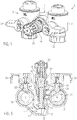
- the Fig. 1 shows a perspective side view of a designated by reference numeral 1 shut-off valve, which comprises a uniform metallic and cast housing 2.
- This housing 2 is formed substantially H-shaped with two legs 3, 4 and a web 5 connecting these legs 3, 4 (see. Fig. 2A ).
- the legs 3, 4 form connections at their respective ends, namely a connection 6 for a supply pipe section of the heating system, not shown, and a connection 7 for the discharge of the flow.
- the corresponding leg 3 accordingly forms a channel 8 for the flow.
- the other leg 4 forms a channel 9 for the return with associated Connections 10 for the supply of the return and connection 11 for the derivation of the return from.
- a circulation channel 12 is recessed within the housing 2, in particular the Fig. 5 can be seen.
- This circulation channel 12 is provided with a valve seat 13, which is integrally formed on the housing 2.
- the housing 2 forms on its side opposite the valve seat 13 a nozzle-shaped receptacle 14 for a marked with reference numeral 15 thermostatic valve.
- the thermostatic valve 15 has a thermostat housing 16 with a receptacle for an expansion element 17 of a thermostat controller 18.
- the expansion element 17 acts on a plate 19, which is held biased against the force of a spring 20 in the direction of the expansion element 17.
- a plunger 21 is coupled, which carries a valve body 22.
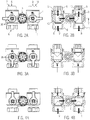
- each of the channels 8, 9 each have a three-way ball valve element 30, 31 is provided.
- the ball valve element 30, 31 respectively connected shafts 32, 33 connected thereto lever members 34, 35, the ball valve elements 30, 31 are brought into different positions.
- FIGS. 2A, 2B show the normal position in which the passages formed in the ball valve element 30, 31 are aligned such that the channel 8 for the supply of the preceding heating water, the channel 9 for the return of the returning heating water and the circulation channel 12 as Bypass between the flow and the return of the heating water flows through the latter, depending on the position of the thermostatic valve 15.
- Marked with reference numeral 36 marks on the surface of the lever elements illustrate the continuity of the corresponding shut-off valve 1 for the forward flow V and the return flow R to the TWES ,
- Plotted directional arrows Z indicate in this normal position, the thermally controlled circulation flow.
- each of the ball valve elements 30, 31 is set so that the channels 8, 9 are already shut off in the region of the terminal 6 and 11 respectively.
- This opposite Page is then depressurized.
- Fig. 3A, 3B shown position is thus suitable both for the replacement of components on this side facing away from the check valve 1 as well as for maintenance, repair, cleaning or replacement of the thermostatic valve 15 or parts thereof.
- FIG. 4A, 4B show a station maintenance position in which the area located on the other side of the coming of the central heating water flow V or the leading to this return R area is shut off. So can be exchanged or serviced in this position, connected to the corresponding side by the armature 1 TWES total or parts thereof. Nevertheless, the circulation of the entire system is maintained because the circulation channel 12 remains open in this station maintenance position, ie the coming of the central hot water preparation flow V communicates via the circulation channel 12 with the leading to the central hot water treatment return R.
- the Fig. 6 shows an example of the installation of the previously discussed embodiment of a check valve 1 in a TWES, whose components are explained in more detail below.
- the TWES has a housing base 40, which is usually mounted on a building wall and covered with a cover, not shown. Between the housing base 40 and the cover are components for controlling water flows and a heat exchanger 42, which is designed as a plate heat exchanger and is connected via Schumachervorlaufrohre 44 with the port 7 for the flow of the shut-off valve 1.
- the coming from a central heating hot water is introduced as a primary medium in the heat exchanger 42 and discharged via heating water return pipes 46 and discharged through the connection 10 for the return flow through the shut-off valve 1.
- a differential pressure regulator 48 is connected between the Bankworthvorlauf- and return pipes 44, 46.
- a differential pressure regulator 48 is connected between the Bankwasservorlauf- and return pipes 44, 46.
- From the Schuingervorlaufrohren 44 also goes from a Banklessvorlauftechnisch for an apartment 50, which is connected via a shut-off heating water flow apartment 52 on the outside of the TWES.
- a shut-off valve heating water return home 54 via which the return of the heating water from the apartment is returned to the TWES.
- a designated by reference numeral 56 heating water return line for the apartment is provided with a zone valve 58 and flows through a three-way control valve 60 in one of the Edelwasserschreiblaufrohre 46th
- shut-off valve 1 Height equal to the shut-off valve 1 and the previously discussed shut-off valves with reference numerals 52 and 54 are other valves, namely a shut-off DHW warm 62, which is connected via a line for hot drinking water 64 to the outlet of the secondary side of the heat exchanger 42. About this shut-off valve 62, the supply of the connected apartment with warm drinking water.
- a shut-off valve drinking water is cold, which is connected via a line for cold drinking water 68 with the interposition of a strainer 70 with a supply line 72 for cold drinking water, which is connected via a shut-off valve 74 to the cold water supply of the building.
- Cold water from the public supply network is introduced into the TWES via this shut-off valve 74.
- reference numeral 76 designates a shut-off valve, via which warm drinking water circulating from the home can be introduced into the TWES.
- a circulation pump 78 is provided in the TWES, which circulates the warm drinking water in the apartment and depending on the consumption within the apartment admixed to the guided through the supply line TWK 72 cold drinking water, so that it can be supplied to the heat exchanger 42 for heating.
- a volume flow and temperature sensor 80 is interposed, which is connected in terms of data with a controller 82, which also processes the signals from temperature sensors 84 and also a motor 86 to the position of the three-way control valve 60th controls.
Abstract
Description
- Die vorliegende Erfindung betrifft ein Absperrventil für ein Heizungssystem mit einem Ventilgehäuse, das einen Kanal für einen Vorlauf und einen Kanal für einen Rücklauf sowie einen die beiden Kanäle kurzschließenden Zirkulationskanal ausbildet. In dem Zirkulationskanal ist ein Ventilsitz vorgesehen, dem ein Ventilkörper eines Thermostatventiles zugeordnet ist. Dieses Thermostatventil hat ein Thermostatelement, welches als Stellelement für den Ventilkörper vorgesehen ist und durch die Temperatur des in dem Absperrventil geführten Heizungswassers gestellt wird.
- Das erfindungsgemäße Ventil kommt insbesondere als Zirkulationsbrücke zum Einsatz, die zusammen mit einer Trinkwassererwärmungsstation (TWES) verbaut wird. Dabei wird der Trinkwassererwärmungsstation Heizungswasser zugeführt, welches in einem Wärmetauscher in der TWES zu erwärmendes Brauchwasser erwärmt, so dass warmes Brauchwasser in einer durch die TWES angeschlossenen Einheit, beispielsweise einer Wohneinheit, zur Verfügung steht. Dieser Ausgestaltung eines Heizungssystems liegt die Überlegung zugrunde, dass lediglich das Heizungswasser in dem oder den Gebäude zirkulieren muss und warmes Brauchwasser dezentral in den jeweiligen TWES mittels Wärmetauscher bereitgestellt wird. Dadurch kann das Verrohrungsaufwand für die Bereitstellung von warmem Brauchwasser vermindert werden.
- Wenn ein entsprechendes Heizungssystem in einem großen Mehrfamilienhaus oder mehreren Häuser mit zentraler Heizungswasseraufbereitung verbaut wird, ergibt sich ein mitunter weitläufiges Rohrleitungsnetz für das Heizungswasser. Insbesondere im Sommerbetrieb, wenn kein Heizwärmebedarf in den jeweiligen Einheiten besteht, kann es passieren, dass bei längerer Nichtnutzung der Trinkwassererwärmung in allen Einheiten oder in allen Einheiten eines Teilbereiches das Heizungswasser in dem entsprechenden Gebäude oder Gebäudeteil nicht in Bewegung ist und auskühlt. Besteht dann ein Bedarf an Trinkwarmwasser, so dauert es recht lange, bis das Heizungswasser aus dem Kellerbereich eines Gebäudes an die entsprechende TWES gelangt und Wärme mit dem zu erwärmenden Trinkwasser tauschen kann. Dies ist nicht zumutbar. Aus diesem Grund wird in solchen Heizungssystemen ein thermostatisch geregelter Bypass montiert, und zwar üblicherweise an derjenigen Stelle eines Stranges für die Heizwasserzirkulation, die der Wärmequelle am entferntesten vorgesehen ist. Dieser Bypass wird auch als Zirkulationsbrücke bezeichnet. Er sorgt dafür, dass aufgrund thermostatischer Regelung bedingt durch die Temperatur des Heizungswassers an der entsprechenden Position jeweils eine Zirkulation gewährleistet wird. So kommt die Zirkulation des Heizungswassers auch im Sommerbetrieb nicht zum Erliegen.
- Die vorliegende Erfindung will ein Absperrventil für ein Heizungssystems der eingangs genannten Art angeben, welches einen hohen praktischen Wert bietet, dabei kompakt bauend ist und sich leicht zwischen Vorlauf- und Rücklaufleitungen und der TWES montieren lässt.
- Mit der vorliegenden Erfindung wird zur Lösung des Problems ein Absperrventil mit den Merkmalen von Anspruch 1 angegeben. Dieses Ventil hat in dem Kanal für den Vorlauf und/oder in dem Kanal für den Rücklauf ein Absperrorgan, das zwischen einer Normalstellung, einer Ventilwartungsstellung und einer Stationswartungsstellung schaltbar ist. In der Normalstellung ist der Kanal durchgängig und mit dem Zirkulationskanal verbunden. In der Ventilwartungsstellung besteht keine Strömungsverbindung zwischen dem Kanal und dem Zirkulationskanal. Dieser Zirkulationskanal zumindest gegenüber zu der zentralen Heizungswasseraufbereitung führenden Rohren abgesperrt. Die Strömung zwischen dem Zirkulationskanal und dem Kanal für den Vorlauf bzw. den Rücklauf ist unterbrochen. So kann kein Heizungswasser von dem Kanal für den Vorlauf bzw. den Kanal für den Rücklauf in den Zirkulationskanal gelangen. In der Stationswartungsstellung ist der Kanal in Bezug auf den Zirkulationskanal auf der der zentralen Heizungswasseraufbereitung gegenüberliegenden Seite abgesperrt, der Zirkulationskanal hingegen für die Zirkulation von Heizungswasser, das von der zentralen Heizungswasseraufbereitung zugeführt bzw. dorthin abgeleitet wird, durchgängig.
- Bei dem erfindungsgemäßen Absperrventil werden die Kanäle und der Zirkulationskanal üblicherweise in einem einheitlichen Ventilgehäuse ausgebildet. Es handelt sich üblicherweise um ein Gussgehäuse aus den üblichen Legierungen, die für die Herstellung von wasserführenden Bauteilen Verwendung finden, wie insbesondere Kupferlegierungen oder Edelstahl. Die Kanäle sind üblicherweise endseitig mit Anschlusselementen für den Anschluss des Absperrventils an die Verrohrung des Heizungssystems, namentlich die Rohre für den Vorlauf und den Rücklauf versehen. Dabei können diese Anschlüsse einteilig an dem Ventilgehäuse ausgebildet sein. Sie können ebenso gut durch mit dem Ventilgehäuse verbundene Anschlussstutzen ausgebildet sein. Dies ist insbesondere dann zu bevorzugen, wenn das Absperrorgan der vorliegenden Erfindung als Kugelventilelement ausgebildet und dichtend in dem Ventilgehäuse aufgenommen ist. In diesem Fall ist bevorzugt eine Buchse in das Ventilgehäuse dichtend eingesetzt, welche das Kugelventilelement innerhalb des Ventilgehäuses fixiert und einseitig abdichtet. Diese Buchse kann Innen- oder Außengewinde für den Anschluss der Verrohrung des Heizungssystems aufweisen. Das Heizungssystem kann auch mittels Pressverbindung angeschlossen sein und so kann das Ventilgehäuse selbst oder eine daran montierte Buchse entsprechende Anschlussflächen für eine Pressverbindung aufweisen.
- Das erfindungsgemäße Absperrventil hat ein Thermostatventil, welches üblicherweise eine Voreinstellung verwirklicht, um den Ventilkörper des Thermostatventils innerhalb des Ventilgehäuses und relativ zu dem Ventilsitz zu stellen, und zwar üblicherweise durch manuelles Verschrauben an einem Stellelement des Thermostatventils. Des Weiteren ist in an sich bekannter Weise ein Thermostatelement vorgesehen, welches durch die Temperatur des in dem Absperrventil geführten Heizungswassers gestellt ist, um abhängig von der Wassertemperatur den Durchgang durch den Zirkulationskanal zu verengen, gegebenenfalls zu verschließen oder zu erweitern, um eine Zirkulation und damit einen Bypass zwischen dem Vorlauf und dem Rücklauf abhängig von der Temperatur des über den Vorlauf einströmenden Heizungswassers zu regeln. Bei verhältnismäßig kaltem Heizungswasser macht das Thermostatventil vermehrt auf, um durch vermehrte Zirkulationsströmung eine Erhöhung der Vorlauftemperatur zu erreichen.
- In der Normalstellung erlaubt das erfindungsgemäße Absperrventil zum einen eine Zirkulationsströmung, durch welche die vorlaufseitige Temperatur auf einem gewünschten Wert gehalten wird. Bei einer Änderung der Vorlauftemperatur öffnet oder schließt das Thermostatventil. Die Regelung erfolgt mit dem Ziel, eine möglichst konstante Wunschtemperatur auf der Vorlauflseite bereitzustellen. So steht Energie für das Zapfen von Warmwasser bzw. die Heizung der Einheit unmittelbar an der TWES an, insbesondere dann, wenn das erfindungsgemäße Absperrventil die Schnittstelle zwischen TWES und der Verrohrung des Heizungssystems für den Vorlauf und den Rücklauf zu dem TWES bildet. Das TWES ist dabei vorzugsweise in einem einheitlichen Gehäuse vorgesehen, welches über das erfindungsgemäße Absperrventil eine Anschlussmöglichkeit für den Vorlauf und den Rücklauf des Heizungssystems bereitstellt.
- In der Normalstellung kann dementsprechend durch die Kanäle Heizungswasser in das TWES eintreten und aus diesem abgezogen werden. Eine Zirkulation unter Einbeziehung des TWES ist möglich, so dass beispielsweise im Winterbetrieb in der Normalstellung Heizungswasser in der Einheit zirkulieren und diese beheizen kann.
- In der Ventilwartungsstellung ist in der Regel weder der Kanal noch der Zirkulationskanal durchgängig. Sofern sowohl am Vorlauf als auch am Rücklauf Absperrorgane vorgesehen sind, wird durch die Ventilwartungsstellung der Zirkulationskanal drucklos gestellt, um beispielsweise das thermostatische Regulierventil zu warten, auszutauschen oder zu reparieren. Das Absperrorgan kann vorzugsweise so vorgesehen sein, dass in der Ventilwartungsstellung auch der dem jeweiligen Absperrorgan zugeordnete Kanal gegenüber zu der zentralen Heizungswasseraufbereitung abgesperrt ist. So kann in dieser Ventilwartungsstellung auch die über das erfindungsgemäße Absperrventil angeschlossene TWES gewartet werden. Jedenfalls bietet aber das erfindungsgemäße Ventil in der Stationswartungsstellung die Möglichkeit einer Zirkulation durch den Zirkulationskanal, thermisch gesteuert durch das Thermostatventil, bei vollständigem Abschluss der TWES, um eine oder mehrere Komponenten der TWES zu reparieren oder auszutauschen. Trotz der Absperrung der TWES in der Stationswartungsstellung ist die Zirkulation weiterhin gegeben, da der an die zentrale Heizungswasseraufbereitung und an die Zirkulationsleitung angeschlossene Bereich des Kanals noch mit dem zu der zentralen Heizungswasseraufbereitung führenden Rohr kommuniziert. So können auch längere Wartungsarbeiten durchgeführt werden, ohne dass die thermische Stabilität des gesamten Systems beeinträchtigt wird und die weiteren TWES des Gebäudes in der gewünschten Weise mit Heizungswasser in der gewünschten Temperatur versorgt werden.
- Weitere Einzelheiten und Vorteile der vorliegenden Erfindung ergeben sich aus der nachfolgenden Beschreibung eines Ausführungsbeispiels in Verbindung mit der Zeichnung. In dieser zeigen:
- Fig. 1
- eine perspektivische Seitenansicht eines Ausführungsbeispiels eines erfindungsgemäßen Absperrventils;
- Fig. 2A, 2B
- eine Draufsicht bzw. eine Längsschnittansicht des Ausführungsbeispiels nach
Fig. 1 in der Normalstellung der Absperrorgane; - Fig. 3A, 3B
- Darstellungen gemäß
Fig. 2A, 2B in der Ventilwartungsstellung der Absperrorgane; - Fig. 4A, 4B
- die Darstellungen nach den
Fig. 2A, 3A bzw. 2B, 3B in der Stationswartungsstellung der Absperrorgane; - Fig. 5
- eine Schnittansicht entlang der Linie V-V gemäß der Darstellung in
Fig. 2B ; und - Fig. 6
- ein Ausführungsbeispiel einer TWES mit dem in dem
Fig. 1 bis 5 gezeigten Ausführungsbeispiel des Absperrventils. - Die
Fig. 1 zeigt eine perspektivische Seitenansicht eines mit Bezugszeichen 1 gekennzeichneten Absperrventils, welches ein einheitliches metallisches und gegossenes Gehäuse 2 umfasst. Dieses Gehäuse 2 ist im Wesentlichen H-förmig mit zwei Schenkeln 3, 4 und einem diese Schenkel 3, 4 verbindenden Steg 5 ausgebildet (vgl.Fig. 2A ). Die Schenkel 3, 4 bilden an ihren jeweiligen Enden Anschlüsse aus, nämlich einen Anschluss 6 für eine den Vorlauf zuführenden Rohrleitungsabschnitt des nicht gezeigten Heizungssystems und einen Anschluss 7 für das Ableiten des Vorlaufs. Der entsprechende Schenkel 3 bildet dementsprechend einen Kanal 8 für den Vorlauf aus. Der andere Schenkel 4 bildet einen Kanal 9 für den Rücklauf mit zugeordneten Anschlüssen 10 für die Zuleitung des Rücklaufs und Anschluss 11 für die Ableitung des Rücklaufs aus. - Zwischen den beiden Kanälen 8, 9 ist ein Zirkulationskanal 12 innerhalb des Gehäuses 2 ausgespart, der insbesondere der
Fig. 5 zu entnehmen ist. Dieser Zirkulationskanal 12 ist mit einem Ventilsitz 13 versehen, der einteilig an dem Gehäuse 2 ausgebildet ist. - Das Gehäuse 2 bildet an seiner dem Ventilsitz 13 gegenüberliegenden Seite eine stutzenförmige Aufnahme 14 für ein mit Bezugszeichen 15 gekennzeichnetes Thermostatventil aus. Das Thermostatventil 15 hat ein Thermostatgehäuse 16 mit einer Aufnahme für ein Dehnstoffelement 17 eines Thermostatreglers 18. Das Dehnstoffelement 17 wirkt auf einen Teller 19 ein, der gegen die Kraft einer Feder 20 in Richtung auf das Dehnstoffelement 17 vorgespannt gehalten ist. Mit dem Teller 19 ist ein Stößel 21 gekoppelt, der einen Ventilkörper 22 trägt. Durch Verschrauben einer Kappe 23 des Thermostatreglers 18 relativ zu dem Thermostatgehäuse 16 kann der Stößel 21 und damit das Thermostatventil 15 voreingestellt werden.
- Wie die
Fig. 1 bis 4 verdeutlichen, ist in jedem der Kanäle 8, 9 jeweils ein Dreiwege-Kugelventilelement 30, 31 vorgesehen. Über mit dem Kugelventilelement 30, 31 jeweils verbundene Wellen 32, 33 mit daran angeschlossenen Hebelelementen 34, 35 können die Kugelventilelemente 30, 31 in verschiedene Stellungen gebracht werden. - Dabei zeigen die
Fig. 1 sowie 2A, 2B die Normalstellung, in welcher die in dem Kugelventilelement 30, 31 jeweils ausgebildeten Durchgänge so ausgerichtet sind, dass der Kanal 8 für den Vorlauf von dem vorlaufenden Heizungswasser, der Kanal 9 für den Rücklauf von dem rücklaufenden Heizungswasser und der Zirkulationskanal 12 als Bypass zwischen dem Vorlauf und dem Rücklauf von dem Heizungswasser durchströmt ist, letzterer abhängig von der Stellung des Thermostatventils 15. Mit Bezugszeichen 36 gekennzeichnete Markierungen auf der Oberfläche der Hebelelemente verdeutlichen die Durchgängigkeit des entsprechenden Absperrventils 1 für die Vorlauflaufströmung V und die Rücklaufströmung R zu dem TWES. Die inFig. 5 eingezeichneten Richtungspfeile Z deuten in dieser Normalstellung die thermisch gesteuerte Zirkulationsströmung an. - Wie die Markierungen und deren Ausrichtung nach
Fig. 3A belegen, ist in der dort gezeigten Ventilwartungsstellung jedes der Kugelventilelemente 30, 31 so gestellt, dass die Kanäle 8, 9 bereits im Bereich des Anschlusses 6 bzw. 11 abgesperrt sind. So gelangt weder vorlaufendes noch rücklaufendes Heizungswasser zu dem Zirkulationskanal und auch nicht auf die der Warmwasseraufbereitung gegenüberliegende Seite des Absperrventils 1. Diese gegenüberliegende Seite ist danach drucklos gestellt. Die inFig. 3A, 3B gezeigte Stellung eignet sich somit sowohl zum Austausch von Komponenten auf dieser abgewandten Seite des Absperrventils 1 wie auch zur Wartung, Reparatur, Reinigung oder dem Austausch des Thermostatventils 15 oder Teile davon. - Die
Fig. 4A, 4B zeigen schließlich eine Stationswartungsstellung, in welcher der auf der anderen Seite des von der zentralen Heizwasseraufbereitung kommenden Vorlaufs V bzw. des zu dieser führenden Rücklaufs R befindliche Bereich abgesperrt ist. So kann in dieser Stellung das auf der entsprechenden Seite durch die Armatur 1 angeschlossene TWES insgesamt oder Teile davon ausgetauscht oder gewartet werden. Gleichwohl bleibt die Zirkulation des Gesamtsystems erhalten, da der Zirkulationskanal 12 in dieser Stationswartungsstellung offen bleibt, d. h. der von der zentralen Heißwasseraufbereitung kommende Vorlauf V über den Zirkulationskanal 12 mit dem zu der zentralen Heißwasseraufbereitung führenden Rücklauf R kommuniziert. - Die
Fig. 6 zeigt ein Beispiel für den Einbau des zuvor diskutierten Ausführungsbeispiels eines Absperrventils 1 in einem TWES, dessen Komponenten nachstehend näher erläutert werden. as TWES hat eine Gehäusebasis 40, die üblicherweise an einer Gebäudewand montiert ist und mit einer nicht gezeigten Abdeckung abgedeckt ist. Zwischen der Gehäusebasis 40 und der Abdeckung befinden sich Komponenten zur Steuerung von Wasserströmen und ein Wärmetauscher 42, der als Plattenwärmetauscher ausgebildet ist und über Heizwasservorlaufrohre 44 mit dem Anschluss 7 für den Vorlauf des Absperrventils 1 verbunden ist. Das von einer Zentralheizung kommende Warmwasser wird als primäres Medium in den Wärmetauscher 42 eingeleitet und über Heizungswasserrücklaufrohre 46 abgeleitet und über den Anschluss 10 für den Rücklauf durch das Absperrventil 1 abgeleitet. Zwischen den Heizwasservorlauf- und Rücklaufrohren 44, 46 ist ein Differenzdruckregler 48 geschaltet. Von den Heizwasservorlaufrohren 44 geht ferner eine Heizwasservorlaufleitung für eine Wohnung 50 ab, die über ein Absperrventil Heizwasser-Vorlauf Wohnung 52 an der Außenseite der TWES anschließbar ist. Daneben befindet sich eine Absperrventil-Heizwasser-Rücklauf Wohnung 54, über welches der Rücklauf des Heizwassers aus der Wohnung in das TWES zurückgeleitet wird. Eine mit Bezugszeichen 56 gekennzeichnete Heizwasserrücklaufleitung für die Wohnung ist mit einem Zonenventil 58 versehen und mündet über ein Drei-Wege-Regelventil 60 in eines der Heizwasserrücklaufrohre 46. - Höhengleich zu dem Absperrventil 1 und den zuvor diskutieren Absperrventilen mit Bezugszeichen 52 und 54 befinden sich weitere Ventile, nämlich ein Absperrventil Trinkwasser warm 62, das über eine Leitung für warmes Trinkwasser 64 an den Auslass der Sekundärseite des Wärmetauschers 42 angeschlossen ist. Über dieses Absperrventil 62 erfolgt die Versorgung der angeschlossenen Wohnung mit warmem Trinkwasser.
- Mit Bezugszeichen 66 ist ein Absperrventil Trinkwasser kalt gekennzeichnet, welches über eine Leitung für kaltes Trinkwasser 68 unter Zwischenschaltung eines Schmutzfängers 70 mit einer Zuleitung 72 für kaltes Trinkwasser verbunden ist, die über ein Absperrventil 74 mit dem Kaltwasseranschluss des Gebäudes verbindbar ist. Über dieses Absperrventil 74 wird kaltes Trinkwasser aus dem öffentlichen Versorgungsnetz in das TWES eingeleitet. Die Weiterleitung des kalten Trinkwassers an die Wohnung erfolgt über das Absperrventil 66.
- Mit Bezugszeichen 76 ist schließlich ein Absperrventil gekennzeichnet, über welches aus der Wohnung zirkulierendes warmes Trinkwasser in das TWES eingeleitet werden kann. Hierzu ist in dem TWES eine Zirkulationspumpe 78 vorgesehen, die das warme Trinkwasser in der Wohnung zirkulieren lässt und je nach Verbrauchslage innerhalb der Wohnung dem durch die Zuleitung TWK 72 geführten kalten Trinkwasser zumischt, so dass dieses dem Wärmetauscher 42 zur Erwärmung zugeführt werden kann. Zur Steuerung dieser Zuströmung auf der Sekundärseite des Wärmetauschers 42 ist ein Volumenstrom- und Temperatursensor 80 zwischengeschaltet, der datenmäßig mit einer Regelung 82 verbunden ist, die auch die Signale von Temperatursensoren 84 verarbeitet und auch einen Motor 86 zur Stellung des Drei-Wege-Regelventils 60 ansteuert.
- Damit ist ein Ausführungsbeispiel einer bevorzugten Anwendung des erfindungsgemäßen Absperrventils verdeutlicht.
-
- 1
- Absperrventil
- 2
- Gehäuse
- 3
- Schenkel
- 4
- Schenkel
- 5
- Steg
- 6
- Anschluss Zuleitung Vorlauf
- 7
- Anschluss Ableitung Vorlauf
- 8
- Kanal Vorlauf
- 9
- Kanal Rücklauf
- 10
- Anschluss Zuleitung Rücklauf
- 11
- Anschluss Ableitung Rücklauf
- 12
- Zirkulationskanal
- 13
- Ventilsitz
- 14
- Aufnahme
- 15
- Thermostatventil
- 16
- Thermostatgehäuse
- 17
- Dehnstoffelement
- 18
- Thermostatregler
- 19
- Teller
- 20
- Feder
- 21
- Stößel
- 22
- Ventilkörper
- 23
- Kappe
- 30
- Kugelventilelement
- 31
- Kugelventilelement
- 32
- Welle
- 33
- Welle
- 34
- Hebelelement
- 35
- Hebelelement
- 36
- Markierung
- 40
- Gehäusebasis
- 42
- Wärmetauscher
- 44
- Heizwasservorlaufrohre
- 46
- Heizwasserrücklaufrohre
- 48
- Differenzdruckregler
- 50
- Heizwasservorlaufleitung für Wohnung
- 52
- Absperrventil HW-Vorlauf-WG
- 54
- Absperrventil HW-Rücklauf-WG
- 56
- Heizwasserrücklaufleitung für Wohnung
- 58
- Zonenventil
- 60
- Drei-Wege-Regelventil
- 62
- Absperrventil TWW
- 64
- TWW-Leitung
- 66
- Absperrventil TWK
- 68
- TWK-Leitung
- 70
- Schmutzfänger
- 72
- TWK-Zuleitung
- 74
- Absperrventil TWK Zentrale Versorgung
- 76
- Absperrventil TWW Zirkulation
- 78
- Zirkulationspumpe
- 80
- Volumenstrom- und Temperatursensor
- 82
- Regelung
- 84
- Temperatursensor
- 86
- Motor
- V
- Vorlauf
- R
- Rücklauf
- Z
- Zirkulation
Claims (3)
- Absperrventil (1) für ein Heizungssystem mit einem Ventilgehäuse (2), das zwischen einem Kanal (8) für einen Vorlauf und einem Kanal (9) für einen Rücklauf und einen die beiden Kanäle (8, 9) kurzschließenden Zirkulationskanal (12) ausbildet, in dem ein Ventilsitz (13) vorgesehen ist, dem ein Ventilkörper (22) eines Thermostatventils (15) zugeordnet ist, das ein durch die Temperatur des geführten Heizungswassers gestelltes Thermostatelement (17) aufweist, wobei in dem Kanal (8) für den Vorlauf und/oder den Kanal (9) für den Rücklauf ein Absperrorgan (30, 31) vorgesehen ist, das zwischen einer Normalstellung, in der der Kanal (8, 9) durchgängig und mit dem Zirkulationskanal (12) verbunden ist, einer Ventilwartungsstellung, in der der Kanal (8, 9) gegenüber dem Zirkulationskanal (12) abgesperrt ist, und einer Stationswartungsstellung, in der der Kanal (8, 9) abgesperrt und der Zirkulationskanal (12) durchgängig ist, schaltbar ist.
- Absperrventil (1) nach Anspruch 1, dadurch gekennzeichnet, dass das Absperrorgan als Kugelventilelement (30; 31) ausgebildet ist.
- Heizungssystem in einem Gebäude mit einem Vorlauf und einem Rücklauf und zumindest einer an Vorlauf und Rücklauf angeschlossenen Trinkwassererwärmungsstation, dadurch gekennzeichnet, dass zwischen dem Vorlauf und dem Rücklauf ein Zirkulationskanal (12) mit einem Ventilsitz (13) vorgesehen ist, dem ein Ventilkörper (22) eines Thermostatventils (15) zugeordnet ist, das ein durch die Temperatur des geführten Heizungswassers gestelltes Thermostatelement aufweist, und mit zumindest einem Absperrorgan (30, 31), das zwischen einer Normalstellung, in der der Kanal (8, 9) durchgängig und mit dem Zirkulationskanal (12) verbunden ist, einer Ventilwartungsstellung, in der der Kanal (8, 9) gegenüber dem Zirkulationskanal (12) abgesperrt ist, und einer Stationswartungsstellung, in der der Kanal (8, 9) abgesperrt und der Zirkulationskanal (12) durchgängig ist, schaltbar ist.
Applications Claiming Priority (1)
| Application Number | Priority Date | Filing Date | Title |
|---|---|---|---|
| DE202015006660.7U DE202015006660U1 (de) | 2015-09-22 | 2015-09-22 | Absperrventil für ein Heizungssystem |
Publications (2)
| Publication Number | Publication Date |
|---|---|
| EP3147574A1 true EP3147574A1 (de) | 2017-03-29 |
| EP3147574B1 EP3147574B1 (de) | 2018-06-20 |
Family
ID=57083091
Family Applications (1)
| Application Number | Title | Priority Date | Filing Date |
|---|---|---|---|
| EP16189738.4A Not-in-force EP3147574B1 (de) | 2015-09-22 | 2016-09-20 | Absperrventil für ein heizungssystem und heizungssystem |
Country Status (2)
| Country | Link |
|---|---|
| EP (1) | EP3147574B1 (de) |
| DE (1) | DE202015006660U1 (de) |
Cited By (2)
| Publication number | Priority date | Publication date | Assignee | Title |
|---|---|---|---|---|
| CN107763254A (zh) * | 2017-11-22 | 2018-03-06 | 鹤山市址山镇百思图卫浴厂 | 一种具有防烫功能的控水装置 |
| WO2021094258A1 (en) | 2019-11-14 | 2021-05-20 | Braathen Thor F | Valve |
Families Citing this family (3)
| Publication number | Priority date | Publication date | Assignee | Title |
|---|---|---|---|---|
| EA036897B1 (ru) * | 2017-01-30 | 2021-01-13 | И.В.А.Р. С.П.А. | Устройство и способ регулирования систем отопления |
| DE202017002700U1 (de) | 2017-05-19 | 2018-08-23 | Gebr. Kemper Gmbh + Co. Kg Metallwerke | Modul zur Wasserversorgung einer Wohneinheit |
| DE202017005077U1 (de) | 2017-09-29 | 2019-01-02 | Gebr. Kemper Gmbh + Co. Kg Metallwerke | Warmwasserversorgung einer Wohneinheit |
Citations (6)
| Publication number | Priority date | Publication date | Assignee | Title |
|---|---|---|---|---|
| FR2676530A3 (en) * | 1991-05-15 | 1992-11-20 | Caleffi Spa | Valvular unit (valve-containing unit) for combined (combination) boilers |
| WO1994018509A1 (de) * | 1993-02-05 | 1994-08-18 | Herz Armaturen Aktiengesellschaft | Adapterarmatur zum wahlweisen anschluss eines heizkörpers |
| DE4306610C1 (de) * | 1993-03-03 | 1994-08-25 | Centra Buerkle Gmbh & Co | Mischarmatur |
| DE19633930A1 (de) * | 1996-08-22 | 1998-02-26 | Kermi Gmbh | Monolithischer Wärmespeicherschrank |
| AT413056B (de) * | 2004-09-22 | 2005-10-15 | Stricker Erwin | Brauchwasserbereiter |
| EP1895245A2 (de) * | 2006-08-31 | 2008-03-05 | Watts Industries Italia S.r.l. | Einteiliges Multifunktionsventil zum Zuführen und Steuern einer Flüssigkeit für Benutzergeräte wie Heizvorrichtungen und dergleichen |
-
2015
- 2015-09-22 DE DE202015006660.7U patent/DE202015006660U1/de not_active Expired - Lifetime
-
2016
- 2016-09-20 EP EP16189738.4A patent/EP3147574B1/de not_active Not-in-force
Patent Citations (6)
| Publication number | Priority date | Publication date | Assignee | Title |
|---|---|---|---|---|
| FR2676530A3 (en) * | 1991-05-15 | 1992-11-20 | Caleffi Spa | Valvular unit (valve-containing unit) for combined (combination) boilers |
| WO1994018509A1 (de) * | 1993-02-05 | 1994-08-18 | Herz Armaturen Aktiengesellschaft | Adapterarmatur zum wahlweisen anschluss eines heizkörpers |
| DE4306610C1 (de) * | 1993-03-03 | 1994-08-25 | Centra Buerkle Gmbh & Co | Mischarmatur |
| DE19633930A1 (de) * | 1996-08-22 | 1998-02-26 | Kermi Gmbh | Monolithischer Wärmespeicherschrank |
| AT413056B (de) * | 2004-09-22 | 2005-10-15 | Stricker Erwin | Brauchwasserbereiter |
| EP1895245A2 (de) * | 2006-08-31 | 2008-03-05 | Watts Industries Italia S.r.l. | Einteiliges Multifunktionsventil zum Zuführen und Steuern einer Flüssigkeit für Benutzergeräte wie Heizvorrichtungen und dergleichen |
Cited By (3)
| Publication number | Priority date | Publication date | Assignee | Title |
|---|---|---|---|---|
| CN107763254A (zh) * | 2017-11-22 | 2018-03-06 | 鹤山市址山镇百思图卫浴厂 | 一种具有防烫功能的控水装置 |
| WO2021094258A1 (en) | 2019-11-14 | 2021-05-20 | Braathen Thor F | Valve |
| NO345644B1 (no) * | 2019-11-14 | 2021-05-25 | Braathen Thor F | Ventiler for vannvarmere med 1 eller 2 stusser og oppvarming fra ekstern varme kilde |
Also Published As
| Publication number | Publication date |
|---|---|
| EP3147574B1 (de) | 2018-06-20 |
| DE202015006660U1 (de) | 2016-12-23 |
Similar Documents
| Publication | Publication Date | Title |
|---|---|---|
| EP3147574B1 (de) | Absperrventil für ein heizungssystem und heizungssystem | |
| EP2154436B1 (de) | Verfahren und Vorrichtung zur Wärmenutzung | |
| EP2354677B1 (de) | Nutzung von Wärme aus den Fernwärmerücklauf | |
| DE102008013124A1 (de) | Mehrkreisige Heizungsanlage | |
| DE3622139C2 (de) | ||
| DE3916195C2 (de) | Wasserversorgungsanlage | |
| EP1792125B1 (de) | Brauchwasserbereiter | |
| EP0825387B1 (de) | Hydraulikbaugruppe, anschliessbar an eine kombinierte Heizwasser- und Sanitärwasseranlage | |
| DE102010014431B4 (de) | Verfahren und Vorrichtung zur Nutzung der Wärmeenergieresourcen eines Gebäudes | |
| EP2204619B1 (de) | Vorrichtung und verfahren für einen optimierten betrieb eines klimatisierungssystems und klimatisierungssystem | |
| DE102016106817A1 (de) | Verfahren und Anlage zur Steuerung des Betriebes und der thermischen Desinfektion von Warmwasser-Zirkulationsanlagen | |
| EP1385072B1 (de) | Regulierventil | |
| DE10254889B4 (de) | Regeltechnische Lösung für eine Wassererwärmungsanlage | |
| DE202017002700U1 (de) | Modul zur Wasserversorgung einer Wohneinheit | |
| EP0290846A1 (de) | Fernwärme-Uebernahmestation | |
| DE202013000593U1 (de) | Regelventil für Heizkörper | |
| EP0700501B1 (de) | Anschlussarmatur für den anschluss von heizkörpern eines heizkreislaufes einer gebäudeheizanlage an deren wärmequelle | |
| DE102014008319B4 (de) | Raumtemperatur-Regelung für eine Flächenheizung | |
| DE4308941C2 (de) | Anordnung zur Warmwasserbereitstellung für mit Gaswandgeräten beheizte Durchlaufspeicher | |
| DE202015006669U1 (de) | Satellit für eine Zentralheizung oder Fernheizung mit Voreinstellung für mehrere Funktionen | |
| DE102006054968B4 (de) | Versorgungssystem für Heiz- oder Kühlwasser und Verfahren zum Betrieb solch eines Versorgungssystems | |
| DE102022127744A1 (de) | Zentralheizungssystem und Verfahren zum Betrieb und/oder zur Steuerung und/oder zur Regelung eines Zentralheizungssystems | |
| WO2024083998A1 (de) | Zentralheizungssystem und verfahren zum betrieb und/oder zur steuerung und/oder zur regelung eines zentralheizungssystems | |
| AT502853A1 (de) | Heizungsanlage mit mindestens einer wärmequelle | |
| DE202019005741U1 (de) | Kombiniertes System zum Erhitzen von Haushaltswasser und von Medium zur Gebäudeheizung und/oder zum Kühlen von Heizmedium zur Gebäudekühlung |
Legal Events
| Date | Code | Title | Description |
|---|---|---|---|
| PUAI | Public reference made under article 153(3) epc to a published international application that has entered the european phase |
Free format text: ORIGINAL CODE: 0009012 |
|
| AK | Designated contracting states |
Kind code of ref document: A1 Designated state(s): AL AT BE BG CH CY CZ DE DK EE ES FI FR GB GR HR HU IE IS IT LI LT LU LV MC MK MT NL NO PL PT RO RS SE SI SK SM TR |
|
| AX | Request for extension of the european patent |
Extension state: BA ME |
|
| 17P | Request for examination filed |
Effective date: 20170309 |
|
| RBV | Designated contracting states (corrected) |
Designated state(s): AL AT BE BG CH CY CZ DE DK EE ES FI FR GB GR HR HU IE IS IT LI LT LU LV MC MK MT NL NO PL PT RO RS SE SI SK SM TR |
|
| RIC1 | Information provided on ipc code assigned before grant |
Ipc: F24D 17/00 20060101ALI20171208BHEP Ipc: F24D 19/10 20060101ALI20171208BHEP Ipc: F16K 11/22 20060101ALI20171208BHEP Ipc: F24D 19/00 20060101ALI20171208BHEP Ipc: F24D 3/10 20060101AFI20171208BHEP Ipc: F16K 31/00 20060101ALI20171208BHEP |
|
| GRAP | Despatch of communication of intention to grant a patent |
Free format text: ORIGINAL CODE: EPIDOSNIGR1 |
|
| INTG | Intention to grant announced |
Effective date: 20180124 |
|
| GRAS | Grant fee paid |
Free format text: ORIGINAL CODE: EPIDOSNIGR3 |
|
| GRAA | (expected) grant |
Free format text: ORIGINAL CODE: 0009210 |
|
| AK | Designated contracting states |
Kind code of ref document: B1 Designated state(s): AL AT BE BG CH CY CZ DE DK EE ES FI FR GB GR HR HU IE IS IT LI LT LU LV MC MK MT NL NO PL PT RO RS SE SI SK SM TR |
|
| REG | Reference to a national code |
Ref country code: GB Ref legal event code: FG4D Free format text: NOT ENGLISH |
|
| REG | Reference to a national code |
Ref country code: IE Ref legal event code: FG4D Free format text: LANGUAGE OF EP DOCUMENT: GERMAN |
|
| REG | Reference to a national code |
Ref country code: AT Ref legal event code: REF Ref document number: 1010872 Country of ref document: AT Kind code of ref document: T Effective date: 20180715 |
|
| REG | Reference to a national code |
Ref country code: DE Ref legal event code: R096 Ref document number: 502016001282 Country of ref document: DE |
|
| REG | Reference to a national code |
Ref country code: NL Ref legal event code: MP Effective date: 20180620 |
|
| PG25 | Lapsed in a contracting state [announced via postgrant information from national office to epo] |
Ref country code: LT Free format text: LAPSE BECAUSE OF FAILURE TO SUBMIT A TRANSLATION OF THE DESCRIPTION OR TO PAY THE FEE WITHIN THE PRESCRIBED TIME-LIMIT Effective date: 20180620 Ref country code: BG Free format text: LAPSE BECAUSE OF FAILURE TO SUBMIT A TRANSLATION OF THE DESCRIPTION OR TO PAY THE FEE WITHIN THE PRESCRIBED TIME-LIMIT Effective date: 20180920 Ref country code: FI Free format text: LAPSE BECAUSE OF FAILURE TO SUBMIT A TRANSLATION OF THE DESCRIPTION OR TO PAY THE FEE WITHIN THE PRESCRIBED TIME-LIMIT Effective date: 20180620 Ref country code: SE Free format text: LAPSE BECAUSE OF FAILURE TO SUBMIT A TRANSLATION OF THE DESCRIPTION OR TO PAY THE FEE WITHIN THE PRESCRIBED TIME-LIMIT Effective date: 20180620 Ref country code: NO Free format text: LAPSE BECAUSE OF FAILURE TO SUBMIT A TRANSLATION OF THE DESCRIPTION OR TO PAY THE FEE WITHIN THE PRESCRIBED TIME-LIMIT Effective date: 20180920 |
|
| REG | Reference to a national code |
Ref country code: LT Ref legal event code: MG4D |
|
| PG25 | Lapsed in a contracting state [announced via postgrant information from national office to epo] |
Ref country code: GR Free format text: LAPSE BECAUSE OF FAILURE TO SUBMIT A TRANSLATION OF THE DESCRIPTION OR TO PAY THE FEE WITHIN THE PRESCRIBED TIME-LIMIT Effective date: 20180921 Ref country code: LV Free format text: LAPSE BECAUSE OF FAILURE TO SUBMIT A TRANSLATION OF THE DESCRIPTION OR TO PAY THE FEE WITHIN THE PRESCRIBED TIME-LIMIT Effective date: 20180620 Ref country code: HR Free format text: LAPSE BECAUSE OF FAILURE TO SUBMIT A TRANSLATION OF THE DESCRIPTION OR TO PAY THE FEE WITHIN THE PRESCRIBED TIME-LIMIT Effective date: 20180620 Ref country code: RS Free format text: LAPSE BECAUSE OF FAILURE TO SUBMIT A TRANSLATION OF THE DESCRIPTION OR TO PAY THE FEE WITHIN THE PRESCRIBED TIME-LIMIT Effective date: 20180620 |
|
| PG25 | Lapsed in a contracting state [announced via postgrant information from national office to epo] |
Ref country code: NL Free format text: LAPSE BECAUSE OF FAILURE TO SUBMIT A TRANSLATION OF THE DESCRIPTION OR TO PAY THE FEE WITHIN THE PRESCRIBED TIME-LIMIT Effective date: 20180620 |
|
| PG25 | Lapsed in a contracting state [announced via postgrant information from national office to epo] |
Ref country code: CZ Free format text: LAPSE BECAUSE OF FAILURE TO SUBMIT A TRANSLATION OF THE DESCRIPTION OR TO PAY THE FEE WITHIN THE PRESCRIBED TIME-LIMIT Effective date: 20180620 Ref country code: PL Free format text: LAPSE BECAUSE OF FAILURE TO SUBMIT A TRANSLATION OF THE DESCRIPTION OR TO PAY THE FEE WITHIN THE PRESCRIBED TIME-LIMIT Effective date: 20180620 Ref country code: SK Free format text: LAPSE BECAUSE OF FAILURE TO SUBMIT A TRANSLATION OF THE DESCRIPTION OR TO PAY THE FEE WITHIN THE PRESCRIBED TIME-LIMIT Effective date: 20180620 Ref country code: RO Free format text: LAPSE BECAUSE OF FAILURE TO SUBMIT A TRANSLATION OF THE DESCRIPTION OR TO PAY THE FEE WITHIN THE PRESCRIBED TIME-LIMIT Effective date: 20180620 Ref country code: IS Free format text: LAPSE BECAUSE OF FAILURE TO SUBMIT A TRANSLATION OF THE DESCRIPTION OR TO PAY THE FEE WITHIN THE PRESCRIBED TIME-LIMIT Effective date: 20181020 Ref country code: EE Free format text: LAPSE BECAUSE OF FAILURE TO SUBMIT A TRANSLATION OF THE DESCRIPTION OR TO PAY THE FEE WITHIN THE PRESCRIBED TIME-LIMIT Effective date: 20180620 |
|
| PG25 | Lapsed in a contracting state [announced via postgrant information from national office to epo] |
Ref country code: ES Free format text: LAPSE BECAUSE OF FAILURE TO SUBMIT A TRANSLATION OF THE DESCRIPTION OR TO PAY THE FEE WITHIN THE PRESCRIBED TIME-LIMIT Effective date: 20180620 Ref country code: SM Free format text: LAPSE BECAUSE OF FAILURE TO SUBMIT A TRANSLATION OF THE DESCRIPTION OR TO PAY THE FEE WITHIN THE PRESCRIBED TIME-LIMIT Effective date: 20180620 Ref country code: IT Free format text: LAPSE BECAUSE OF FAILURE TO SUBMIT A TRANSLATION OF THE DESCRIPTION OR TO PAY THE FEE WITHIN THE PRESCRIBED TIME-LIMIT Effective date: 20180620 |
|
| REG | Reference to a national code |
Ref country code: DE Ref legal event code: R097 Ref document number: 502016001282 Country of ref document: DE |
|
| REG | Reference to a national code |
Ref country code: DE Ref legal event code: R119 Ref document number: 502016001282 Country of ref document: DE |
|
| PLBE | No opposition filed within time limit |
Free format text: ORIGINAL CODE: 0009261 |
|
| STAA | Information on the status of an ep patent application or granted ep patent |
Free format text: STATUS: NO OPPOSITION FILED WITHIN TIME LIMIT |
|
| PG25 | Lapsed in a contracting state [announced via postgrant information from national office to epo] |
Ref country code: MC Free format text: LAPSE BECAUSE OF FAILURE TO SUBMIT A TRANSLATION OF THE DESCRIPTION OR TO PAY THE FEE WITHIN THE PRESCRIBED TIME-LIMIT Effective date: 20180620 |
|
| 26N | No opposition filed |
Effective date: 20190321 |
|
| PG25 | Lapsed in a contracting state [announced via postgrant information from national office to epo] |
Ref country code: DK Free format text: LAPSE BECAUSE OF FAILURE TO SUBMIT A TRANSLATION OF THE DESCRIPTION OR TO PAY THE FEE WITHIN THE PRESCRIBED TIME-LIMIT Effective date: 20180620 |
|
| REG | Reference to a national code |
Ref country code: BE Ref legal event code: MM Effective date: 20180930 |
|
| REG | Reference to a national code |
Ref country code: IE Ref legal event code: MM4A |
|
| PG25 | Lapsed in a contracting state [announced via postgrant information from national office to epo] |
Ref country code: LU Free format text: LAPSE BECAUSE OF NON-PAYMENT OF DUE FEES Effective date: 20180920 |
|
| PG25 | Lapsed in a contracting state [announced via postgrant information from national office to epo] |
Ref country code: IE Free format text: LAPSE BECAUSE OF NON-PAYMENT OF DUE FEES Effective date: 20180920 Ref country code: DE Free format text: LAPSE BECAUSE OF NON-PAYMENT OF DUE FEES Effective date: 20190402 |
|
| PG25 | Lapsed in a contracting state [announced via postgrant information from national office to epo] |
Ref country code: SI Free format text: LAPSE BECAUSE OF FAILURE TO SUBMIT A TRANSLATION OF THE DESCRIPTION OR TO PAY THE FEE WITHIN THE PRESCRIBED TIME-LIMIT Effective date: 20180620 Ref country code: FR Free format text: LAPSE BECAUSE OF NON-PAYMENT OF DUE FEES Effective date: 20180930 Ref country code: BE Free format text: LAPSE BECAUSE OF NON-PAYMENT OF DUE FEES Effective date: 20180930 |
|
| PG25 | Lapsed in a contracting state [announced via postgrant information from national office to epo] |
Ref country code: AL Free format text: LAPSE BECAUSE OF FAILURE TO SUBMIT A TRANSLATION OF THE DESCRIPTION OR TO PAY THE FEE WITHIN THE PRESCRIBED TIME-LIMIT Effective date: 20180620 |
|
| PG25 | Lapsed in a contracting state [announced via postgrant information from national office to epo] |
Ref country code: MT Free format text: LAPSE BECAUSE OF FAILURE TO SUBMIT A TRANSLATION OF THE DESCRIPTION OR TO PAY THE FEE WITHIN THE PRESCRIBED TIME-LIMIT Effective date: 20180620 |
|
| PG25 | Lapsed in a contracting state [announced via postgrant information from national office to epo] |
Ref country code: TR Free format text: LAPSE BECAUSE OF FAILURE TO SUBMIT A TRANSLATION OF THE DESCRIPTION OR TO PAY THE FEE WITHIN THE PRESCRIBED TIME-LIMIT Effective date: 20180620 |
|
| PG25 | Lapsed in a contracting state [announced via postgrant information from national office to epo] |
Ref country code: PT Free format text: LAPSE BECAUSE OF FAILURE TO SUBMIT A TRANSLATION OF THE DESCRIPTION OR TO PAY THE FEE WITHIN THE PRESCRIBED TIME-LIMIT Effective date: 20180620 |
|
| REG | Reference to a national code |
Ref country code: CH Ref legal event code: PL |
|
| PG25 | Lapsed in a contracting state [announced via postgrant information from national office to epo] |
Ref country code: CY Free format text: LAPSE BECAUSE OF FAILURE TO SUBMIT A TRANSLATION OF THE DESCRIPTION OR TO PAY THE FEE WITHIN THE PRESCRIBED TIME-LIMIT Effective date: 20180620 Ref country code: MK Free format text: LAPSE BECAUSE OF NON-PAYMENT OF DUE FEES Effective date: 20180620 Ref country code: HU Free format text: LAPSE BECAUSE OF FAILURE TO SUBMIT A TRANSLATION OF THE DESCRIPTION OR TO PAY THE FEE WITHIN THE PRESCRIBED TIME-LIMIT; INVALID AB INITIO Effective date: 20160920 |
|
| PG25 | Lapsed in a contracting state [announced via postgrant information from national office to epo] |
Ref country code: CH Free format text: LAPSE BECAUSE OF NON-PAYMENT OF DUE FEES Effective date: 20190930 Ref country code: LI Free format text: LAPSE BECAUSE OF NON-PAYMENT OF DUE FEES Effective date: 20190930 |
|
| GBPC | Gb: european patent ceased through non-payment of renewal fee |
Effective date: 20200920 |
|
| PG25 | Lapsed in a contracting state [announced via postgrant information from national office to epo] |
Ref country code: GB Free format text: LAPSE BECAUSE OF NON-PAYMENT OF DUE FEES Effective date: 20200920 |
|
| REG | Reference to a national code |
Ref country code: AT Ref legal event code: MM01 Ref document number: 1010872 Country of ref document: AT Kind code of ref document: T Effective date: 20210920 |
|
| PG25 | Lapsed in a contracting state [announced via postgrant information from national office to epo] |
Ref country code: AT Free format text: LAPSE BECAUSE OF NON-PAYMENT OF DUE FEES Effective date: 20210920 |