EP3146934A1 - Pads für orthodontische klammern, orthodontische klammern und verfahren zur herstellung orthodontischer klammern - Google Patents
Pads für orthodontische klammern, orthodontische klammern und verfahren zur herstellung orthodontischer klammern Download PDFInfo
- Publication number
- EP3146934A1 EP3146934A1 EP16190488.3A EP16190488A EP3146934A1 EP 3146934 A1 EP3146934 A1 EP 3146934A1 EP 16190488 A EP16190488 A EP 16190488A EP 3146934 A1 EP3146934 A1 EP 3146934A1
- Authority
- EP
- European Patent Office
- Prior art keywords
- pad
- bracket
- porous
- superelastic metal
- bonding
- Prior art date
- Legal status (The legal status is an assumption and is not a legal conclusion. Google has not performed a legal analysis and makes no representation as to the accuracy of the status listed.)
- Granted
Links
- 238000000034 method Methods 0.000 title claims abstract description 25
- 229910052751 metal Inorganic materials 0.000 claims abstract description 101
- 239000002184 metal Substances 0.000 claims abstract description 101
- 239000000853 adhesive Substances 0.000 claims abstract description 73
- 230000001070 adhesive effect Effects 0.000 claims abstract description 73
- 239000011148 porous material Substances 0.000 claims abstract description 49
- 239000007787 solid Substances 0.000 claims abstract description 25
- 239000000843 powder Substances 0.000 claims description 19
- 239000000203 mixture Substances 0.000 claims description 16
- PXHVJJICTQNCMI-UHFFFAOYSA-N Nickel Chemical compound [Ni] PXHVJJICTQNCMI-UHFFFAOYSA-N 0.000 claims description 12
- 238000006243 chemical reaction Methods 0.000 claims description 11
- 239000000945 filler Substances 0.000 claims description 8
- 239000006260 foam Substances 0.000 claims description 7
- 239000010936 titanium Substances 0.000 claims description 7
- OKTJSMMVPCPJKN-UHFFFAOYSA-N Carbon Chemical group [C] OKTJSMMVPCPJKN-UHFFFAOYSA-N 0.000 claims description 6
- 238000002156 mixing Methods 0.000 claims description 6
- 229910052759 nickel Inorganic materials 0.000 claims description 6
- 229910052719 titanium Inorganic materials 0.000 claims description 6
- RTAQQCXQSZGOHL-UHFFFAOYSA-N Titanium Chemical compound [Ti] RTAQQCXQSZGOHL-UHFFFAOYSA-N 0.000 claims description 5
- 239000000463 material Substances 0.000 claims description 5
- 239000011230 binding agent Substances 0.000 claims description 4
- 238000001816 cooling Methods 0.000 claims description 4
- 238000000151 deposition Methods 0.000 claims description 4
- 239000012704 polymeric precursor Substances 0.000 claims description 4
- 238000005245 sintering Methods 0.000 claims description 4
- 238000003466 welding Methods 0.000 claims description 4
- 238000002844 melting Methods 0.000 claims description 2
- 230000008018 melting Effects 0.000 claims description 2
- 239000002923 metal particle Substances 0.000 claims description 2
- 238000003825 pressing Methods 0.000 claims description 2
- 238000005507 spraying Methods 0.000 claims description 2
- 229910001000 nickel titanium Inorganic materials 0.000 abstract description 21
- HZEWFHLRYVTOIW-UHFFFAOYSA-N [Ti].[Ni] Chemical compound [Ti].[Ni] HZEWFHLRYVTOIW-UHFFFAOYSA-N 0.000 description 21
- 210000003298 dental enamel Anatomy 0.000 description 16
- 238000011282 treatment Methods 0.000 description 10
- 230000008569 process Effects 0.000 description 8
- 229910045601 alloy Inorganic materials 0.000 description 6
- 239000000956 alloy Substances 0.000 description 6
- 238000009826 distribution Methods 0.000 description 6
- 150000001875 compounds Chemical class 0.000 description 3
- 238000009434 installation Methods 0.000 description 3
- 230000018984 mastication Effects 0.000 description 3
- 238000010077 mastication Methods 0.000 description 3
- 239000000155 melt Substances 0.000 description 3
- 239000002245 particle Substances 0.000 description 3
- 238000006116 polymerization reaction Methods 0.000 description 3
- 150000003839 salts Chemical class 0.000 description 3
- 239000000126 substance Substances 0.000 description 3
- 206010061274 Malocclusion Diseases 0.000 description 2
- QYKIQEUNHZKYBP-UHFFFAOYSA-N Vinyl ether Chemical compound C=COC=C QYKIQEUNHZKYBP-UHFFFAOYSA-N 0.000 description 2
- 150000001252 acrylic acid derivatives Chemical class 0.000 description 2
- 239000012867 bioactive agent Substances 0.000 description 2
- 238000005229 chemical vapour deposition Methods 0.000 description 2
- 238000005049 combustion synthesis Methods 0.000 description 2
- 230000006835 compression Effects 0.000 description 2
- 238000007906 compression Methods 0.000 description 2
- -1 copper-aluminum-manganese Chemical compound 0.000 description 2
- 238000011049 filling Methods 0.000 description 2
- 239000012530 fluid Substances 0.000 description 2
- 125000000524 functional group Chemical group 0.000 description 2
- 238000005304 joining Methods 0.000 description 2
- 150000002734 metacrylic acid derivatives Chemical class 0.000 description 2
- 150000002739 metals Chemical class 0.000 description 2
- 238000012986 modification Methods 0.000 description 2
- 230000004048 modification Effects 0.000 description 2
- 210000000214 mouth Anatomy 0.000 description 2
- 230000035515 penetration Effects 0.000 description 2
- 230000005855 radiation Effects 0.000 description 2
- 229920005989 resin Polymers 0.000 description 2
- 239000011347 resin Substances 0.000 description 2
- 239000000565 sealant Substances 0.000 description 2
- 230000035939 shock Effects 0.000 description 2
- 239000007921 spray Substances 0.000 description 2
- 229910001220 stainless steel Inorganic materials 0.000 description 2
- 239000010935 stainless steel Substances 0.000 description 2
- 229910000619 316 stainless steel Inorganic materials 0.000 description 1
- 239000006096 absorbing agent Substances 0.000 description 1
- 238000010521 absorption reaction Methods 0.000 description 1
- 239000000654 additive Substances 0.000 description 1
- 230000000844 anti-bacterial effect Effects 0.000 description 1
- 230000000712 assembly Effects 0.000 description 1
- 238000000429 assembly Methods 0.000 description 1
- 230000015572 biosynthetic process Effects 0.000 description 1
- 238000004061 bleaching Methods 0.000 description 1
- 238000005266 casting Methods 0.000 description 1
- 239000004568 cement Substances 0.000 description 1
- 239000000919 ceramic Substances 0.000 description 1
- 230000008859 change Effects 0.000 description 1
- 239000003795 chemical substances by application Substances 0.000 description 1
- 230000001055 chewing effect Effects 0.000 description 1
- 238000002485 combustion reaction Methods 0.000 description 1
- 238000005056 compaction Methods 0.000 description 1
- 239000002537 cosmetic Substances 0.000 description 1
- 230000002939 deleterious effect Effects 0.000 description 1
- 239000003479 dental cement Substances 0.000 description 1
- 210000004268 dentin Anatomy 0.000 description 1
- 210000004513 dentition Anatomy 0.000 description 1
- 238000009792 diffusion process Methods 0.000 description 1
- 230000005489 elastic deformation Effects 0.000 description 1
- 125000003700 epoxy group Chemical group 0.000 description 1
- 239000003822 epoxy resin Substances 0.000 description 1
- 238000001125 extrusion Methods 0.000 description 1
- 239000011888 foil Substances 0.000 description 1
- PCHJSUWPFVWCPO-UHFFFAOYSA-N gold Chemical compound [Au] PCHJSUWPFVWCPO-UHFFFAOYSA-N 0.000 description 1
- 239000010931 gold Substances 0.000 description 1
- 229910052737 gold Inorganic materials 0.000 description 1
- 229910002804 graphite Inorganic materials 0.000 description 1
- 239000010439 graphite Substances 0.000 description 1
- LNEPOXFFQSENCJ-UHFFFAOYSA-N haloperidol Chemical compound C1CC(O)(C=2C=CC(Cl)=CC=2)CCN1CCCC(=O)C1=CC=C(F)C=C1 LNEPOXFFQSENCJ-UHFFFAOYSA-N 0.000 description 1
- 238000001513 hot isostatic pressing Methods 0.000 description 1
- 230000008595 infiltration Effects 0.000 description 1
- 238000001764 infiltration Methods 0.000 description 1
- 230000002045 lasting effect Effects 0.000 description 1
- 229910001338 liquidmetal Inorganic materials 0.000 description 1
- 238000011068 loading method Methods 0.000 description 1
- 238000004519 manufacturing process Methods 0.000 description 1
- 230000007246 mechanism Effects 0.000 description 1
- 239000013528 metallic particle Substances 0.000 description 1
- 238000001000 micrograph Methods 0.000 description 1
- 230000003278 mimic effect Effects 0.000 description 1
- 238000004806 packaging method and process Methods 0.000 description 1
- 230000000149 penetrating effect Effects 0.000 description 1
- 230000002093 peripheral effect Effects 0.000 description 1
- 238000007750 plasma spraying Methods 0.000 description 1
- 229920000647 polyepoxide Polymers 0.000 description 1
- 239000002243 precursor Substances 0.000 description 1
- 238000012545 processing Methods 0.000 description 1
- 238000011084 recovery Methods 0.000 description 1
- 230000002787 reinforcement Effects 0.000 description 1
- 230000008439 repair process Effects 0.000 description 1
- 230000000717 retained effect Effects 0.000 description 1
- 239000008247 solid mixture Substances 0.000 description 1
- 238000007711 solidification Methods 0.000 description 1
- 230000008023 solidification Effects 0.000 description 1
- 238000002490 spark plasma sintering Methods 0.000 description 1
- 238000003892 spreading Methods 0.000 description 1
- 230000007480 spreading Effects 0.000 description 1
- 238000010186 staining Methods 0.000 description 1
- 238000010561 standard procedure Methods 0.000 description 1
- 238000005728 strengthening Methods 0.000 description 1
- 238000003786 synthesis reaction Methods 0.000 description 1
- 238000012360 testing method Methods 0.000 description 1
- 230000036346 tooth eruption Effects 0.000 description 1
Images


Classifications
-
- A—HUMAN NECESSITIES
- A61—MEDICAL OR VETERINARY SCIENCE; HYGIENE
- A61C—DENTISTRY; APPARATUS OR METHODS FOR ORAL OR DENTAL HYGIENE
- A61C7/00—Orthodontics, i.e. obtaining or maintaining the desired position of teeth, e.g. by straightening, evening, regulating, separating, or by correcting malocclusions
- A61C7/12—Brackets; Arch wires; Combinations thereof; Accessories therefor
- A61C7/14—Brackets; Fixing brackets to teeth
- A61C7/16—Brackets; Fixing brackets to teeth specially adapted to be cemented to teeth
-
- A—HUMAN NECESSITIES
- A61—MEDICAL OR VETERINARY SCIENCE; HYGIENE
- A61C—DENTISTRY; APPARATUS OR METHODS FOR ORAL OR DENTAL HYGIENE
- A61C7/00—Orthodontics, i.e. obtaining or maintaining the desired position of teeth, e.g. by straightening, evening, regulating, separating, or by correcting malocclusions
- A61C7/12—Brackets; Arch wires; Combinations thereof; Accessories therefor
- A61C7/14—Brackets; Fixing brackets to teeth
- A61C7/141—Brackets with reinforcing structure, e.g. inserts
-
- A—HUMAN NECESSITIES
- A61—MEDICAL OR VETERINARY SCIENCE; HYGIENE
- A61C—DENTISTRY; APPARATUS OR METHODS FOR ORAL OR DENTAL HYGIENE
- A61C7/00—Orthodontics, i.e. obtaining or maintaining the desired position of teeth, e.g. by straightening, evening, regulating, separating, or by correcting malocclusions
- A61C7/12—Brackets; Arch wires; Combinations thereof; Accessories therefor
- A61C7/28—Securing arch wire to bracket
- A61C7/287—Sliding locks
-
- B—PERFORMING OPERATIONS; TRANSPORTING
- B22—CASTING; POWDER METALLURGY
- B22D—CASTING OF METALS; CASTING OF OTHER SUBSTANCES BY THE SAME PROCESSES OR DEVICES
- B22D21/00—Casting non-ferrous metals or metallic compounds so far as their metallurgical properties are of importance for the casting procedure; Selection of compositions therefor
- B22D21/002—Castings of light metals
- B22D21/005—Castings of light metals with high melting point, e.g. Be 1280 degrees C, Ti 1725 degrees C
-
- B—PERFORMING OPERATIONS; TRANSPORTING
- B22—CASTING; POWDER METALLURGY
- B22D—CASTING OF METALS; CASTING OF OTHER SUBSTANCES BY THE SAME PROCESSES OR DEVICES
- B22D25/00—Special casting characterised by the nature of the product
- B22D25/06—Special casting characterised by the nature of the product by its physical properties
-
- B—PERFORMING OPERATIONS; TRANSPORTING
- B22—CASTING; POWDER METALLURGY
- B22F—WORKING METALLIC POWDER; MANUFACTURE OF ARTICLES FROM METALLIC POWDER; MAKING METALLIC POWDER; APPARATUS OR DEVICES SPECIALLY ADAPTED FOR METALLIC POWDER
- B22F3/00—Manufacture of workpieces or articles from metallic powder characterised by the manner of compacting or sintering; Apparatus specially adapted therefor ; Presses and furnaces
- B22F3/10—Sintering only
- B22F3/1017—Multiple heating or additional steps
- B22F3/1021—Removal of binder or filler
-
- B—PERFORMING OPERATIONS; TRANSPORTING
- B22—CASTING; POWDER METALLURGY
- B22F—WORKING METALLIC POWDER; MANUFACTURE OF ARTICLES FROM METALLIC POWDER; MAKING METALLIC POWDER; APPARATUS OR DEVICES SPECIALLY ADAPTED FOR METALLIC POWDER
- B22F3/00—Manufacture of workpieces or articles from metallic powder characterised by the manner of compacting or sintering; Apparatus specially adapted therefor ; Presses and furnaces
- B22F3/10—Sintering only
- B22F3/1039—Sintering only by reaction
-
- B—PERFORMING OPERATIONS; TRANSPORTING
- B22—CASTING; POWDER METALLURGY
- B22F—WORKING METALLIC POWDER; MANUFACTURE OF ARTICLES FROM METALLIC POWDER; MAKING METALLIC POWDER; APPARATUS OR DEVICES SPECIALLY ADAPTED FOR METALLIC POWDER
- B22F3/00—Manufacture of workpieces or articles from metallic powder characterised by the manner of compacting or sintering; Apparatus specially adapted therefor ; Presses and furnaces
- B22F3/10—Sintering only
- B22F3/11—Making porous workpieces or articles
-
- B—PERFORMING OPERATIONS; TRANSPORTING
- B22—CASTING; POWDER METALLURGY
- B22F—WORKING METALLIC POWDER; MANUFACTURE OF ARTICLES FROM METALLIC POWDER; MAKING METALLIC POWDER; APPARATUS OR DEVICES SPECIALLY ADAPTED FOR METALLIC POWDER
- B22F3/00—Manufacture of workpieces or articles from metallic powder characterised by the manner of compacting or sintering; Apparatus specially adapted therefor ; Presses and furnaces
- B22F3/12—Both compacting and sintering
- B22F3/16—Both compacting and sintering in successive or repeated steps
-
- B—PERFORMING OPERATIONS; TRANSPORTING
- B23—MACHINE TOOLS; METAL-WORKING NOT OTHERWISE PROVIDED FOR
- B23K—SOLDERING OR UNSOLDERING; WELDING; CLADDING OR PLATING BY SOLDERING OR WELDING; CUTTING BY APPLYING HEAT LOCALLY, e.g. FLAME CUTTING; WORKING BY LASER BEAM
- B23K31/00—Processes relevant to this subclass, specially adapted for particular articles or purposes, but not covered by only one of the preceding main groups
- B23K31/02—Processes relevant to this subclass, specially adapted for particular articles or purposes, but not covered by only one of the preceding main groups relating to soldering or welding
-
- C—CHEMISTRY; METALLURGY
- C23—COATING METALLIC MATERIAL; COATING MATERIAL WITH METALLIC MATERIAL; CHEMICAL SURFACE TREATMENT; DIFFUSION TREATMENT OF METALLIC MATERIAL; COATING BY VACUUM EVAPORATION, BY SPUTTERING, BY ION IMPLANTATION OR BY CHEMICAL VAPOUR DEPOSITION, IN GENERAL; INHIBITING CORROSION OF METALLIC MATERIAL OR INCRUSTATION IN GENERAL
- C23C—COATING METALLIC MATERIAL; COATING MATERIAL WITH METALLIC MATERIAL; SURFACE TREATMENT OF METALLIC MATERIAL BY DIFFUSION INTO THE SURFACE, BY CHEMICAL CONVERSION OR SUBSTITUTION; COATING BY VACUUM EVAPORATION, BY SPUTTERING, BY ION IMPLANTATION OR BY CHEMICAL VAPOUR DEPOSITION, IN GENERAL
- C23C16/00—Chemical coating by decomposition of gaseous compounds, without leaving reaction products of surface material in the coating, i.e. chemical vapour deposition [CVD] processes
- C23C16/06—Chemical coating by decomposition of gaseous compounds, without leaving reaction products of surface material in the coating, i.e. chemical vapour deposition [CVD] processes characterised by the deposition of metallic material
-
- C—CHEMISTRY; METALLURGY
- C23—COATING METALLIC MATERIAL; COATING MATERIAL WITH METALLIC MATERIAL; CHEMICAL SURFACE TREATMENT; DIFFUSION TREATMENT OF METALLIC MATERIAL; COATING BY VACUUM EVAPORATION, BY SPUTTERING, BY ION IMPLANTATION OR BY CHEMICAL VAPOUR DEPOSITION, IN GENERAL; INHIBITING CORROSION OF METALLIC MATERIAL OR INCRUSTATION IN GENERAL
- C23C—COATING METALLIC MATERIAL; COATING MATERIAL WITH METALLIC MATERIAL; SURFACE TREATMENT OF METALLIC MATERIAL BY DIFFUSION INTO THE SURFACE, BY CHEMICAL CONVERSION OR SUBSTITUTION; COATING BY VACUUM EVAPORATION, BY SPUTTERING, BY ION IMPLANTATION OR BY CHEMICAL VAPOUR DEPOSITION, IN GENERAL
- C23C4/00—Coating by spraying the coating material in the molten state, e.g. by flame, plasma or electric discharge
- C23C4/12—Coating by spraying the coating material in the molten state, e.g. by flame, plasma or electric discharge characterised by the method of spraying
- C23C4/123—Spraying molten metal
-
- A—HUMAN NECESSITIES
- A61—MEDICAL OR VETERINARY SCIENCE; HYGIENE
- A61C—DENTISTRY; APPARATUS OR METHODS FOR ORAL OR DENTAL HYGIENE
- A61C2201/00—Material properties
- A61C2201/007—Material properties using shape memory effect
Definitions
- the present invention relates to orthodontic appliances for use in dental applications and, in particular, to pads for use with orthodontic brackets, orthodontic brackets having pads, and methods of making pads and orthodontic brackets.
- Typical orthodontic brackets may include a bracket body in which an archwire slot is provided to receive an archwire and may also include tie wings or other ligating structures integral with or secured to the bracket body for use in ligating the archwire to the bracket.
- Such bracket structure is generally provided with a tooth engaging structure with which the bracket is secured to the tooth surface.
- Orthodontic appliances are typically secured to the patient's teeth with an adhesive.
- the adhesive is generally applied to a tooth, with the orthodontic appliance then being pressed onto the adhesive. Once cured, the adhesive creates a chemical and/or mechanical bond between the adhesive and the tooth and a chemical and/or mechanical bond with structure on the bracket.
- each of a plurality of orthodontic brackets is adhered to a tooth. The brackets may then be coupled together by an archwire to begin treatment.
- the tooth engaging structure on the bracket often includes a pad that may be either integrally formed with the bracket body or is formed as a separate sheet and then secured to the bracket body.
- the pad may define a bonding surface and may include specific features to facilitate an adhesive bond to the patient's tooth.
- the bonding surface often includes structural elements, such as a mesh or other highly textured structure that includes undercuts, protrusions, or recesses or a combination of these features.
- the adhesive may flow in and around these features during affixation of the bracket to the tooth. Once the adhesive hardens or cures, the adhesive provides a mechanical or interlocking bond between the pad and the tooth.
- Such a bonding surface may be referred to as a "mechanical bonding base.”
- orthodontic brackets are subjected to a variety of forces in addition to forces exerted on brackets by archwires. More particularly, when objects, such as food, forcibly contact orthodontic brackets during chewing, the forces are conveyed by the bracket directly to the adhesive bond securing the bracket to the tooth. When the force exceeds the strength of the bond, the bond may fail catastrophically and the bracket may debond from the tooth. Often it is normal mastication that generates forces that debond the brackets from a patient's tooth.
- bracket debond is a major loss of revenue for the orthodontist.
- a pad is provided for use with an orthodontic bracket that includes a porous superelastic metal structure.
- the porous superelastic metal structure is configured to receive an adhesive for bonding the orthodontic bracket to a tooth.
- the porous superelastic metal structure is a wafer and is impregnated with the adhesive prior to bonding the orthodontic bracket to the tooth.
- the orthodontic bracket includes a bracket body and the porous superelastic metal structure forms a bonding portion that is coupled to the bracket body and that defines a bonding surface.
- the bonding surface receives the adhesive.
- the porous superelastic metal structure defines a pore volume that is substantially uniformly distributed through the thickness of the bonding portion.
- the porous superelastic metal structure defines a pore volume in which a volume fraction of porosity at a location proximate the bracket body is different from a volume fraction of porosity at a location proximate the bonding surface.
- the pad further includes an attachment portion for attaching the bonding portion to the bracket body.
- the attachment portion is substantially solid.
- the attachment portion is made of a metal that is different from the metal of the porous superelastic metal structure.
- the attachment portion is made of a metal that differs from the metal of the bracket body.
- bracket body and the porous superelastic metal structure are integrally formed.
- an orthodontic bracket in one embodiment, includes a bracket body, and a pad extending from the bracket body and including a porous superelastic metal wafer.
- the wafer is impregnated with the adhesive prior to bonding the orthodontic bracket to the tooth.
- bracket body and the pad are integrally formed.
- the porous superelastic metal structure forms a bonding portion that is coupled to the bracket body and defines a bonding surface that is configured to receive the adhesive.
- the pad further includes an attachment portion for attaching the bonding portion to the bracket body.
- the attachment portion is substantially solid.
- a method for making a pad for an orthodontic bracket includes fabricating a porous superelastic metal structure for placement between the orthodontic bracket and a tooth.
- the porous superelastic metal structure is configured to receive an adhesive for bonding the porous superelastic metal structure to the tooth.
- the orthodontic bracket includes a bracket body and the porous superelastic metal structure forms a bonding portion.
- the method further includes fabricating an attachment portion that is to be coupled to the body portion and to the bracket body.
- fabricating the attachment portion includes closing off porosity on one side of the bonding portion by spraying molten metal or tack welding a sheet of metal to one side of the bonding portion.
- fabricating the porous superelastic metal structure includes producing a gradient in a volume fraction of porosity in the porous superelastic metal structure with the highest volume fraction of porosity at one surface.
- fabricating the porous superelastic metal structure includes mixing a nickel-containing powder and a titanium-containing powder, pressing the mixture to form a green body, and igniting a reaction between the nickel-containing powder and the titanium-containing powder in the green body.
- fabricating the porous superelastic metal structure includes mixing a powder of a superelastic metal and a powder of a polymeric binder, placing the mixture in a polymeric precursor foam, and sintering the superelastic metal particles.
- fabricating the porous superelastic metal structure includes vapor depositing a superelastic metal on a prefabricated carbon skeleton.
- fabricating the porous superelastic metal structure includes melting a composition from which the superelastic metal forms upon cooling, mixing a filler material in the melt, pouring the mixture of melted metal and filler into a mold, cooling the mixture, and removing the filler.
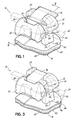
- an orthodontic appliance such as an orthodontic bracket 10 for attachment to a tooth (not shown).
- the orthodontic bracket 10 includes a bracket body 12 and a pad 14.
- the bracket body 12 may be secured to the pad 14 or may be formed integrally with the pad 14, as is described below.
- the pad 14 includes a body that is at least partially made of a porous structure, for example a porous superelastic metal structure. The porosity is open and is thus connected to an outer surface of the pad 14. In this regard, when the orthodontic bracket 10 is secured to a tooth with an adhesive, the adhesive may penetrate into the pores.
- the orthodontic bracket 10 may resist unintentional debonding from the patient's tooth because the superelastic metal of the pad 14 may absorb shear forces and shock associated with normal mastication and other less frequent, but more severe impacts that occasionally occur during treatment. These events may include impact forces, such as from sporting events or other accidental impact to the bracket body 12.
- NiTi may act as a shock absorber. More specifically, NiTi may elastically strain near 6 to 8%. Thus, a pad of NiTi may deform significantly before the bond between the pad 14 and the tooth surface is significantly stressed by the external force.
- the strength of the bond between the orthodontic bracket 10 and the tooth may be in the range in which when the clinician intentionally debonds the orthodontic bracket 10 at the end of treatment, the patient's teeth are not damaged.
- dental assemblies according to the present invention may show improved bond strength.
- the orthodontic bracket 10 includes a movable closure member coupled to the bracket body 12.
- the movable closure member may include a ligating slide 16 slidably coupled with the bracket body 12.
- the bracket body 12 includes an archwire slot 18 formed therein adapted to receive an archwire 20 (shown in phantom) for applying corrective forces to the teeth.
- the ligating slide 16 is movable between an opened position ( Fig. 1 ) in which the archwire 20 is insertable into the archwire slot 18 and a closed position ( Fig. 3 ) in which the archwire 20 is retained within the archwire slot 18.
- the bracket body 12 and the ligating slide 16 collectively form the orthodontic bracket 10 for use in corrective orthodontic treatments.
- the movable closure member is described herein as a ligating slide, the invention is not so limited.
- the movable closure member may include other movable structures (e.g., latch, spring clip, door, etc.) that are capable of moving between an opened and closed position.
- embodiments of the present invention are not limited to self-ligating orthodontic brackets.
- orthodontic brackets, bands, buccal tubes, anchors, caps or other hardware may be attached to a tooth.
- Orthodontic brackets may include those described in U.S. Pat. No. 8,585,398 and in U.S. Patent Publication No.
- twin tie-wing style orthodontic brackets e.g., shown in Figs. 7A-7D
- Figs. 7A-7D twin tie-wing style orthodontic brackets
- the archwire slot 18 may include a base surface 22 and a pair of opposed slot surfaces 24, 26 projecting outwardly from the base surface 22 that collectively define the archwire slot 18 extending in a mesial-distal direction.
- the archwire slot 18 may be designed to receive an orthodontic archwire 20 in any suitable manner.
- twin tie wing style brackets also include an archwire slot but rely on a separate ligature, such as, an elastomeric O-ring or wire, to secure the archwire within the archwire slot.
- bracket 10 unless otherwise indicated, is described herein using a reference frame attached to a labial surface of an anterior tooth on the lower jaw. Consequently, as used herein, terms such as labial, lingual, mesial, distal, occlusal, and gingival used to describe bracket 10 are relative to the chosen reference frame. The embodiments of the invention, however, are not limited to the chosen reference frame and descriptive terms, as the orthodontic bracket 10 may be used on other teeth and in other orientations within the oral cavity. For example, the bracket 10 may also be coupled to the lingual surface of the tooth and be within the scope of the invention. Those of ordinary skill in the art will recognize that the descriptive terms used herein may not directly apply when there is a change in reference frame.
- embodiments of the invention are intended to be independent of location and orientation within the oral cavity and the relative terms used to describe embodiments of the orthodontic bracket are to merely provide a clear description of the embodiments in the drawings.
- the relative terms labial, lingual, mesial, distal, occlusal, and gingival are in no way limiting the invention to a particular location or orientation.
- the bracket body 12 When mounted to the labial surface of a tooth (not shown) carried on the patient's lower jaw and with reference specifically to Fig. 1 , the bracket body 12 has a lingual side 28, an occlusal side 30, a gingival side 32, a mesial side 34, a distal side 36, and a labial side 38.
- the bracket body 12 is configured to be secured to the tooth by an appropriate orthodontic cement or adhesive.
- the lingual side 28 is provided with the pad 14 defining a body or bonding base that is configured to be secured to the surface of the tooth.
- the pad 14 may be coupled to the bracket body 12 as a separate piece or element or, alternatively, the pad 14 may be integrally formed with the bracket body 12, each of which is described below. Further, the pad 14 may be specifically shaped to fit on the surface of the patient's tooth. In that regard, the pad 14 may be customized in shape and in curvature and may therefore have a multitude of configurations different from that shown in Figs. 1-3 . In that regard, it will be appreciated that embodiments of the present invention are not limited to any particular shape of the pad 14.
- the pad 14 has a bonding surface 40 that may be contoured to match the surface of the tooth and may define a peripheral surface or edge 42 that defines a bonding area. As is described below, in embodiments of the invention, at least a portion of the bonding surface 40 is defined by a bonding portion 44 that includes a porous superelastic metal structure having open pores that penetrate into the pad 14.
- the adhesive may cover the bonding area and extend beyond the edge 42 while penetrating into the pores of the porous superelastic metal structure. That is, the adhesive penetrates into the bonding portion 44. Once cured, the adhesive provides a mechanical interlock between the orthodontic bracket 10 and the tooth.
- the porosity extends into the pad 14 and may be referred to as apparent porosity in which the pores are open to the bonding surface 40 and so fluids, such as, an adhesive, may penetrate into the pores.
- Apparent porosity may be referred to as open porosity.
- embodiments of the present invention may exclude closed porosity in which pores are closed off from, or not connected to, a surface though limited amounts of closed porosity may be tolerated.
- the porous structure may comprise a solid volume of superelastic metal with pores defining an open volume in the pad 14. It will be appreciated that the open porosity may be in any form but may include individual pockets that are isolated from one another by regions of metal. The pockets may not be isolated but may interconnect to form networks of channels within the pad 14.
- the porosity may be a combination of interconnected channels and isolated pores or pockets.
- the pad 14 includes a porous superelastic metal structure 48 having a solid volume 52 of the superelastic metal.
- the porous structure 48 includes a three-dimensional framework of superelastic metal (i.e., the solid volume 52) that defines a pore volume 50.
- individual pores of the pore volume 50 are open to the bonding surface 40 and so are capable of receiving fluids, such as adhesives.
- the solid volume 52 may be randomly constructed and so differs from a patterned machined mesh or molded grid. The characteristics of the solid volume 52 to the pore volume 50 may vary.
- the pore volume 50 fraction may be constant throughout the pad 14.
- the bonding portion 44 may include an evenly distributed ratio of solid volume 52 to pore volume 50 through the thickness of the pad 14. Other distributions and ratios are possible.
- the pore volume 50 may not be evenly distributed through the porous structure 48.
- the pore volume 50 may be highest at regions proximate the bonding surface 40 and may then decrease in a direction toward the bracket body 12.
- the bonding portion 44 may include more than one layer of material.
- a layer of solid superelastic metal may be coupled to a porous layer of superelastic metal. In this way, the bonding portion 44 includes two discrete layers of metal that are bonded together. In this embodiment, there may be a boundary between the solid metal and the porous metal. This two-layered body may then be coupled to the bracket body 12 with the porous layer defining the bonding surface 40.
- the pore volume 50 varies continuously through the thickness of the bonding portion 44.
- the pore volume 50 to solid volume 52 of the porous structure 48 may vary from nearly 100% solid (no porosity) adjacent the lingual side 28 of the bracket body 12 to a ratio of less than 100% solid (balance of pore volume) adjacent the bonding surface 40. This distribution may be the result of a gradient in the solid volume 52 starting at 100% solid at or near the lingual side 28 of the bracket body 12 and changing to a larger portion of pore volume 50 at the bonding surface 40.
- This may include a distribution in which the largest volume fraction of porosity is at or near the bonding surface 40 with the volume fraction of porosity being reduced at distances in the bonding portion 44 furthest from the bonding surface 40.
- the gradient may be linear with thickness of the bonding portion 44 or be a nonlinear function of thickness of the bonding portion 44.
- a gradient in porosity may be advantageous when, for example, the pad 14 is being bonded to the bracket body 12. In this regard, a less porous surface of the bonding portion 44 of the pad 14 may improve the mechanical integrity of the interface between the bracket body 12 and the pad 14.
- a gradient in porosity is shown best in Fig. 2 .
- Exemplary microstructures, including porosity, for the pad 14 are shown in Figs. 2A and 2B .
- the porosity may mimic natural porosity found in the enamel of teeth.
- Pores in enamel may be generally defined by rods that are about 4 ⁇ m to about 8 ⁇ m in diameter and are oriented generally perpendicularly to the underlying dentin.
- a rod sheath may surround each rod and together with interrod enamel may define the natural porosity found in enamel.
- the porous superelastic metal structure may be characterized with a similar rod and pore structure and have a similar orientation and extend to a similar depth as the natural porosity in enamel.
- individual pores of the pore volume 50 may have similar pore diameters as the pores of tooth enamel.
- the pore diameter may be about 5 ⁇ m.
- the depth of the pore volume 50 from the bonding surface 40 may vary.
- the pore volume 50 may extend to a depth of a few tens of microns up to a depth of about 250 ⁇ m. In view of the similarity between the porosity found in enamel and the porosity formed in the superelastic metal pad, it is believed that the bond strength with an appropriate adhesive will be around 40 MPa.
- individual pores of the pore volume 50 may be generally aligned with each other.
- the pores may generally be at a right angle to the tooth surface.
- the pores may be generally aligned at a 45 degree angle to the tooth surface. This anisotropy in the microstructure may produce different degrees of performance (e.g., elastic modulus) in different directions to address debonding force.
- the pad 14 is at least partially made of a superelastic metal.
- the superelastic metal may be a nickel-titanium (NiTi) based alloy, a copper-aluminum-manganese (CuAlMn) alloy, a copper-aluminum-beryllium (CuAlBe) alloy, or a copper-aluminum-nickel (CuAlNi) alloy, among others.
- the superelastic metal may be fabricated to have anisotropic properties, particularly with regard to the distribution of the porosity.
- the entirety of the pad 14 may be porous and so functions as the bonding portion 44.
- the pad 14 is coupled directly to the bracket body 12.
- the pad 14 may be secured to the bracket body 12 such as by welding or with an adhesive.
- the pad 14 may include an assembly of an attachment portion 46 coupled to the bonding portion 44. Similar to the embodiment shown in Fig. 1 , the bonding portion 44 defines the bonding surface 40 for bonding the orthodontic bracket 10 to the tooth with adhesive.
- the attachment portion 46 may facilitate attachment of the bonding portion 44 to the bracket body 12. Without being bound by theory, joining of dissimilar metals can sometimes be problematic. As such, bonding a non-superelastic metallic bracket body, for example, made from stainless steel, to superelastic metal may be facilitated by the attachment portion 46 made of a different metal. To that end, the attachment portion 46 is positioned between the bracket body 12 and the bonding portion 44.
- the attachment portion 46 may be a layer of a metal that differs from the bonding portion 44 though it may form a portion of the pad 14, as shown.
- the bonding portion 44 may be a superelastic metal mesh.
- the attachment portion 46 may be solid superelastic metal or a different metal to facilitate attachment of the bonding portion 44 to the bracket body 12.
- the bracket body 12 and the pad 14 may be integrally formed. That is, the body 12 and the pad 14 are formed of a single superelastic metallic body with open porosity (i.e., a volume of porosity) at the bonding surface 40, similar to embodiments described above and shown in Figs. 1 and 3 .
- the pad 14 may be fabricated using the self-propagating high temperature synthesis process, also known as combustion synthesis. This process utilizes high reaction temperatures (e.g., 1200 °C) and short processing times (e.g., seconds to minutes) resulting in homogeneous alloys of desirable stoichiometry.
- superelastic metal e.g., fine, high-purity powders of nickel and titanium (for superelastic NiTi) may be mixed in an inert atmosphere at a low pre-heat temperature (e.g., 300 °C to 400 °C) and pressure (e.g., up to 200 MPa) to form a green (i.e., unsintered or unreacted) compact.
- the green compact may then be sintered by ignition of a self-propagating combustion reaction to produce a solid.
- a specified maximum pre-heat temperature may be chosen to initiate this reaction, which is highly exothermic.
- the compact is ignited at one end.
- the reaction proceeds directionally toward the other end to form a solid.
- the reaction equation for NiTi may be shown by Equation 1: Ni + Ti ⁇ NiTi + 67 kJ / mol
- This reaction may be controlled by, for example, salts or reaction stoichiometry and may result in porous superelastic metal having a desired shape, such as the shape of the pad 14 or, alternatively, the bracket body 12.
- the pad 14 may include a solid volume of superelastic metal having an interconnected porosity of about 45% to about 65%. The percentage of porosity may depend on factors including compaction pressure and particle size distributions, to name only a few.
- the porosity may be in the form of isolated pockets or interconnected pockets that form channels.
- the pockets or channels may have cross sectional dimensions that measure up to 0.5 mm.
- porous superelastic metal may be fabricated using hot isostatic pressing.
- elemental powders of Ni and Ti may be pressurized at or near the melt temperatures (e.g., about 1310 °C), which drives the reaction and solidification of the alloy.
- the atmosphere is controlled due to the combination of high temperature and pressure used in the reaction.
- the pressure determines the degree of porosity in the pad.
- this reaction may be controlled such that the resultant porous NiTi body has a desired shape.
- superelastic powder may be fused and shaped into a porous body using spark plasma sintering.
- This process relies upon compression and electrical energy to sinter metallic particles into a solid body.
- a pulsed current is induced through a die (e.g., made of graphite) to heat and drive necking (i.e., sintering) between particles.
- the quantity and type of porosity may be controlled by the temperature and pressure. In this regard, lower temperatures and pressures may result in increased porosity.
- a "burn out" process may be used to sinter superelastic metal powder into a porous body with a desired shape.
- a mixture of NiTi powder and polymeric binder may be poured into a polymeric precursor foam. This loaded foam may then be heated to vaporize the binder and foam and to begin sintering the NiTi powder.
- the porosity may be generally controlled by the characteristics of the precursor foam.
- the polymeric precursor foam may be shaped to create a porosity gradient (described above) in the pad 14.
- porous superelastic metal may be fabricated by depositing NiTi via chemical vapor deposition (CVD) or chemical vapor infiltration (CVI) on a prefabricated carbon skeleton.
- CVD chemical vapor deposition
- CVI chemical vapor infiltration
- the carbon skeleton does not form a portion of the porous body. Instead, it is mechanically or chemically removed to leave the deposited NiTi body.
- NiTi vapor may be deposited on a prefabricated carbon skeleton shaped to create a gradient in the porosity.
- Other techniques may include traditional casting techniques involving pouring a melt of the superelastic metal over salt in a mold, which is later digested chemically, or by introducing gas to the poured melt to form porosity.
- the porosity may be controlled based on the amount of gas or salt introduced.
- the pad 14 may have a uniform porosity through its thickness.
- a subsequent thermal spray process may be used to create a gradient in the porosity by capping open pores on one surface.
- a porous body may be plasma sprayed with another metal (e.g., 316 stainless steel) on one side.
- the molten or liquid metal droplets fill in or cap a portion of the pore volume 50.
- Capping or filling in the pores on one surface may create a gradient in the pore volume 50 in the pad 14 by reducing or eliminating porosity on one surface.
- the degree of penetration of the droplets determines the gradient in the pore volume 50 and may result in a solid mixture of superelastic metal and the sprayed metal at one surface.
- plasma spraying may result in a completely sealed (e.g., solid) side of the pad 14. More than one layer of superelastic metal having varying degrees of porosity may be bonded together to build a gradient of porosity in the bonding portion 44. It should be recognized that there may be other methods to create a gradient in a porous pad. As an alternative, a sheet of metal may be tack welded to one side of the bonding portion 44 to provide a platform by which the bonding portion 44 is attached to the bracket body 12.
- the pad 14 may then be attached to the bracket body 12, as shown in Fig. 1 . This may be accomplished, for example, by laser bonding the pad 14 to the bracket body 12 or by another metal joining or welding process.
- the clinician may add adhesive 56 to the pad 14 or the pad 14 may be prefilled with the adhesive 56 and packaged as a ready-to-use kit.
- the bonding portion 44 may be designed with a target volume of porosity. A targeted volume of adhesive may be injected into that volume of porosity. This may occur at the manufacturing facility in which case the bracket 10 with preloaded adhesive is packaged for distribution.
- the adhesive 56 may be an un-polymerized orthodontic adhesive partially or fully absorbed by the porous structure 48.
- This prepackaged orthodontic bracket may be offered as the packaged product for a clinician to employ at the time of bonding and therefore may eliminate the tedious intermediate step of manually applying bulk adhesive prior to adhering the bracket 10 to the tooth.
- the prepackaged product provides a tremendous time savings in the office and enables greater bond consistency across the dentition.
- the amount of adhesive 56 may be sufficient to essentially fill all of or only a portion of the pore volume 50 of the pad 14.
- the superelastic metal may be hydrophilic and so advantageously promote the penetration of the adhesive 56 into the pore volume 50 of the bonding portion 44.
- the adhesive 56 may be photopolymerizable or another polymerizable compound known in the art.
- the composition contains a photoinitiator that upon irradiation with actinic radiation initiates the polymerization (or hardening) of the composition.
- photopolymerizable compositions can be free-radically polymerizable or cationically polymerizable.
- Suitable photopolymerizable components that can be used in the compositions as disclosed herein include, for example, epoxy resins (which contain cationically active epoxy groups), vinyl ether resins (which contain cationically active vinyl ether groups), ethylenically unsaturated compounds (which contain free-radically active unsaturated groups, e.g., acrylates and methacrylates), and combinations thereof.
- polymerizable materials that contain both a cationically active functional group and a free-radically active functional group in a single compound. Examples include epoxy-functional acrylates, epoxy-functional methacrylates, and combinations thereof.
- the porous structure 48 acts as a sponge to hold preloaded adhesive in a targeted location.
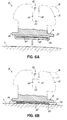
- the clinician may press the bracket 10 against the tooth. This slight manual pressure on the pad 14 may cause the porous structure 48 to elastically compress. During that compression, a thickness of the porous structure 48 is reduced. This may temporarily reduce the pore volume 50 and cause extrusion of the adhesive 56 from the bonding portion 44.
- the adhesive 56 may extend outwardly from the pad 14, as is shown in Fig. 5 , in a controlled manner. When the pressure is released, the porous structure 48 may elastically recover at least a portion of its original dimensions during which any excess adhesive 56 may be reabsorbed. This may minimize the need for post-bonding cleanup.
- the adhesive 56 may be polymerized by standard methods (e.g., photo-initiation).
- a porous wafer 60 of superelastic metal e.g., NiTi
- the wafer 60 may include the porous structure 48 similar to that described above.
- the adhesive 56 may be preloaded at the manufacturer's facility rather than being manually dispensed by the clinician and may fill the pore volume 50.
- the porous wafer 60 may act as a structural or functional element in the preloaded adhesive 56.
- the wafer 60 may retain the adhesive 56 in contact with the pad prior to polymerization. As shown, the adhesive 56 may encapsulate the porous wafer 60.
- the adhesive 56 may wet the porous wafer 60 and so may be less likely to run off the pad 14 prior to installation.
- the porous wafer 60 may hold a low viscosity adhesive in position on the pad 14 during shipment and prior to polymerization. During installation, the porous wafer 60 may facilitate uniform spreading of the adhesive 56 between the bracket 10 and the tooth T.
- the porous wafer 60 may structurally reinforce the adhesive 56. Structural reinforcement may be in addition to any fillers in the adhesive 56 or the wafer 60 may replace the fillers found in conventional adhesives. Once the adhesive polymerizes, the wafer 60 may structurally support the cured adhesive during treatment.
- the porous wafer 60 may be from about 50 ⁇ m to about 500 ⁇ m in thickness.
- the adhesive 56 may then be hardened so that the bracket body 12 is bonded to the tooth. Curing may be effected by visible light radiation or other methods known in the art. When the adhesive cures, it is "rooted" in the pad 14. It will be appreciated that the intimate contact between the bonding portion 44 and the adhesive 56 is promoted by a large surface area of contact between the two, that is, between the relatively large surface area provided by the solid volume 52 and the adhesive 56. Having multiple interlocking bonding sites forces the failure mechanism of debonding to break each independent site. It is believed that the crack propagation between the tooth and the pad 14 within the adhesive bond may be blunted due to the additional energy necessary to start new cracks when multiple interlocking bonding sites are encountered.
- the pad 14 may act as a bioreservoir.
- at least a portion of the pore volume 50 may house additives intended to improve the quality of the bonding of the bracket body 12 to the tooth.
- anti-bacterial, anti-staining (cosmetic), bleaching, and/or re-mineralization agents may be incorporated into a dental sealant or resin.
- the pad 14 may then be impregnated by filling at least a portion of the pore volume 50 with the sealant (not shown).
- the bioactive agent may slow-release at an effective rate to an area adjacent the tooth surface.
- the location of the bioactive agents within the pad 14 may be chosen based on the area(s) adjacent the tooth that are most at risk (i.e., areas that are hygienically hindered).
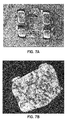
- a porous NiTi base was bonded to an Ormco Mini-TwinTM bracket.
- the assembled bracket and pad are shown in Figs. 7A and 7B .
- the bonding surface of the pad is most clearly shown in Fig. 7B .
- the bracket was stainless steel (i.e., SS 17-4).
- the porous NiTi pad from PorOsteon was a generally rectangular block or sheet and included a layer of 316 SS sprayed via a plasma spray system. Individual pads were machined (i.e., via EDM) from the sheet.
- the porous NiTi pad was gold brazed to the bracket body, specifically to the layer of 316 SS, at 1,950 °F.
- the bracket including the porous NiTi pad was adhered to tooth enamel with a standard Ormco adhesive between a tooth and the pad.
- the bracket bonded to the tooth is shown in Figs. 7C and 7D .
- the porous NiTi base bonded well to the enamel using standard clinical procedures.
- shear bonding tests the bracket debonded from the tooth enamel at about 5 kgf. Debonding occurred between the enamel and the pad and not between the pad and the bracket. It was concluded that the bonding between the porous NiTi pad and the tooth enamel was successful and demonstrated orthodontic applicability.
Landscapes
- Health & Medical Sciences (AREA)
- Engineering & Computer Science (AREA)
- Mechanical Engineering (AREA)
- Chemical & Material Sciences (AREA)
- Veterinary Medicine (AREA)
- Oral & Maxillofacial Surgery (AREA)
- Life Sciences & Earth Sciences (AREA)
- Animal Behavior & Ethology (AREA)
- General Health & Medical Sciences (AREA)
- Public Health (AREA)
- Dentistry (AREA)
- Epidemiology (AREA)
- Manufacturing & Machinery (AREA)
- Chemical Kinetics & Catalysis (AREA)
- Materials Engineering (AREA)
- Metallurgy (AREA)
- Organic Chemistry (AREA)
- Plasma & Fusion (AREA)
- Physics & Mathematics (AREA)
- General Chemical & Material Sciences (AREA)
- Dental Tools And Instruments Or Auxiliary Dental Instruments (AREA)
Applications Claiming Priority (1)
| Application Number | Priority Date | Filing Date | Title |
|---|---|---|---|
| US201562232079P | 2015-09-24 | 2015-09-24 |
Publications (2)
| Publication Number | Publication Date |
|---|---|
| EP3146934A1 true EP3146934A1 (de) | 2017-03-29 |
| EP3146934B1 EP3146934B1 (de) | 2018-04-11 |
Family
ID=56997375
Family Applications (1)
| Application Number | Title | Priority Date | Filing Date |
|---|---|---|---|
| EP16190488.3A Active EP3146934B1 (de) | 2015-09-24 | 2016-09-23 | Pads für orthodontische klammern, orthodontische klammern und verfahren zur herstellung orthodontischer klammern |
Country Status (5)
| Country | Link |
|---|---|
| US (1) | US20170086947A1 (de) |
| EP (1) | EP3146934B1 (de) |
| JP (1) | JP2017060768A (de) |
| KR (1) | KR20170036644A (de) |
| CN (1) | CN107019568A (de) |
Cited By (2)
| Publication number | Priority date | Publication date | Assignee | Title |
|---|---|---|---|---|
| EP3644892A4 (de) * | 2017-06-26 | 2021-03-10 | Murrell, Fred | Kieferorthopädische zahnrückhaltevorrichtungen und verfahren zu ihrer herstellung |
| US20210169616A1 (en) * | 2017-12-08 | 2021-06-10 | Ca Digital Gmbh | Method of producing and deploying orthodontic brackets or attachments |
Families Citing this family (1)
| Publication number | Priority date | Publication date | Assignee | Title |
|---|---|---|---|---|
| KR102010452B1 (ko) | 2017-07-19 | 2019-08-13 | 조선대학교산학협력단 | 개폐 가능한 슬롯 커버를 갖는 교정용 브라켓 |
Citations (6)
| Publication number | Priority date | Publication date | Assignee | Title |
|---|---|---|---|---|
| US4165561A (en) * | 1976-04-15 | 1979-08-28 | American Hospital Supply Corporation | Orthodontic appliance with porous tooth-abutting face |
| CA1219476A (en) * | 1983-07-21 | 1987-03-24 | Gustaf H. Hanson | Orthodontic bracket |
| WO2003026526A2 (en) * | 2001-09-24 | 2003-04-03 | Conform Orthodontics, Inc. | Adjustable orthodontic band |
| US8585398B2 (en) | 2008-08-13 | 2013-11-19 | Ormco Corporation | Aesthetic orthodontic bracket and method of making same |
| WO2014119089A1 (ja) * | 2013-01-30 | 2014-08-07 | トミー株式会社 | 歯列矯正用部材 |
| US20140272758A1 (en) | 2012-12-07 | 2014-09-18 | Ormco Corporation | Connector for coupling an orthodontic appliance to a patient and associated methods |
Family Cites Families (9)
| Publication number | Priority date | Publication date | Assignee | Title |
|---|---|---|---|---|
| US4068379A (en) * | 1977-03-18 | 1978-01-17 | Ormco Corporation | Orthodontic appliance with porous tooth-abutting face |
| US4752221A (en) * | 1981-09-15 | 1988-06-21 | Augusta Developments, Inc. | Orthodontic bracket |
| US5232361A (en) * | 1992-04-06 | 1993-08-03 | Sachdeva Rohit C L | Orthodontic bracket |
| US5263859A (en) * | 1992-05-08 | 1993-11-23 | Tp Orthodontics, Inc. | Relatively flexible bonding pad for an orthodontic ceramic bracket |
| DE19535095A1 (de) * | 1995-09-21 | 1997-03-27 | Foerster Bernhard Gmbh | Kieferorthopädisches Teil aus Metall |
| US6050815A (en) * | 1996-03-15 | 2000-04-18 | 3M Innovative Properties Company | Precoated dental cement |
| US7175428B2 (en) * | 2004-07-02 | 2007-02-13 | Nicholson James A | Shape memory self-ligating orthodontic brackets |
| CN201684030U (zh) * | 2010-04-21 | 2010-12-29 | 江阴东大新材料研究院 | 多孔正畸托槽 |
| CN204072365U (zh) * | 2014-07-23 | 2015-01-07 | 北京圣玛特科技有限公司 | 一种带有双层滑盖的自锁托槽 |
-
2016
- 2016-09-23 JP JP2016185326A patent/JP2017060768A/ja not_active Ceased
- 2016-09-23 EP EP16190488.3A patent/EP3146934B1/de active Active
- 2016-09-23 US US15/273,756 patent/US20170086947A1/en not_active Abandoned
- 2016-09-26 KR KR1020160122951A patent/KR20170036644A/ko unknown
- 2016-09-26 CN CN201610852934.7A patent/CN107019568A/zh active Pending
Patent Citations (6)
| Publication number | Priority date | Publication date | Assignee | Title |
|---|---|---|---|---|
| US4165561A (en) * | 1976-04-15 | 1979-08-28 | American Hospital Supply Corporation | Orthodontic appliance with porous tooth-abutting face |
| CA1219476A (en) * | 1983-07-21 | 1987-03-24 | Gustaf H. Hanson | Orthodontic bracket |
| WO2003026526A2 (en) * | 2001-09-24 | 2003-04-03 | Conform Orthodontics, Inc. | Adjustable orthodontic band |
| US8585398B2 (en) | 2008-08-13 | 2013-11-19 | Ormco Corporation | Aesthetic orthodontic bracket and method of making same |
| US20140272758A1 (en) | 2012-12-07 | 2014-09-18 | Ormco Corporation | Connector for coupling an orthodontic appliance to a patient and associated methods |
| WO2014119089A1 (ja) * | 2013-01-30 | 2014-08-07 | トミー株式会社 | 歯列矯正用部材 |
Cited By (2)
| Publication number | Priority date | Publication date | Assignee | Title |
|---|---|---|---|---|
| EP3644892A4 (de) * | 2017-06-26 | 2021-03-10 | Murrell, Fred | Kieferorthopädische zahnrückhaltevorrichtungen und verfahren zu ihrer herstellung |
| US20210169616A1 (en) * | 2017-12-08 | 2021-06-10 | Ca Digital Gmbh | Method of producing and deploying orthodontic brackets or attachments |
Also Published As
| Publication number | Publication date |
|---|---|
| EP3146934B1 (de) | 2018-04-11 |
| US20170086947A1 (en) | 2017-03-30 |
| KR20170036644A (ko) | 2017-04-03 |
| JP2017060768A (ja) | 2017-03-30 |
| CN107019568A (zh) | 2017-08-08 |
Similar Documents
| Publication | Publication Date | Title |
|---|---|---|
| US10945817B1 (en) | Orthodontic appliances and methods of making and using same | |
| EP3146934B1 (de) | Pads für orthodontische klammern, orthodontische klammern und verfahren zur herstellung orthodontischer klammern | |
| EP2077795A1 (de) | Vorgeformte formbare mehrschichtige dentalartikel | |
| Bishara et al. | Ceramic brackets: something old, something new, a review | |
| EP2614810A2 (de) | Auf Thermoplast basierte Polymerhaftzusammensetzungen und Vorrichtungen für ihre Verwendung in Zahnanwendungen | |
| US20140363778A1 (en) | Orthodontic FFM Resin Rope Appliance | |
| US20160296303A1 (en) | Orthodontic System Anchoring Method and Apparatus | |
| El-Mowafy et al. | Resin-bonded fixed partial dentures--a literature review with presentation of a novel approach. | |
| US10039616B2 (en) | Orthodontic bracket | |
| WO2008033758A2 (en) | Preformed malleable solid crown | |
| CA2672305C (en) | Dental impression film, and a method of manufacturing the dental impression film | |
| JPH09238955A (ja) | 非対称の結合構造体を有する歯科矯正具 | |
| US20160184067A1 (en) | Orthodontic anchoring method and apparatus | |
| JPH04231040A (ja) | 歯の複合修復において用いられるマトリックスバンド | |
| JP2014507971A (ja) | 圧縮性材料を含む固着可能な歯科用アセンブリ及び方法 | |
| EP2881076B1 (de) | Labiale befestigungsvorrichtung zur verwendung mit orthodontischen hilfs- und lingualem anwendungssystem | |
| Sahmali et al. | Comparison of in vitro tensile bond strengths of luting cements to metallic and tooth-colored posts | |
| DJ et al. | Adhesive properties of bonded orthodontic retainers to enamel: Stainless steel wire versus fiber-reinforced composites | |
| US6644968B2 (en) | Orthodontic appliance | |
| US20070111152A1 (en) | Pre-cemented orthodontic appliances | |
| JP3444829B2 (ja) | セラミック歯科補綴材 | |
| JP6396429B2 (ja) | 歯列矯正用接着材および歯列矯正用接着材キット | |
| WO2013025489A1 (en) | Laser etched sintered ceramic orthodontic brackets | |
| US11992385B1 (en) | Orthodontic archwire stop and methods of making and using same | |
| JP3586296B2 (ja) | 人工歯根の製造方法及び製造装置 |
Legal Events
| Date | Code | Title | Description |
|---|---|---|---|
| PUAI | Public reference made under article 153(3) epc to a published international application that has entered the european phase |
Free format text: ORIGINAL CODE: 0009012 |
|
| AK | Designated contracting states |
Kind code of ref document: A1 Designated state(s): AL AT BE BG CH CY CZ DE DK EE ES FI FR GB GR HR HU IE IS IT LI LT LU LV MC MK MT NL NO PL PT RO RS SE SI SK SM TR |
|
| AX | Request for extension of the european patent |
Extension state: BA ME |
|
| 17P | Request for examination filed |
Effective date: 20170912 |
|
| RBV | Designated contracting states (corrected) |
Designated state(s): AL AT BE BG CH CY CZ DE DK EE ES FI FR GB GR HR HU IE IS IT LI LT LU LV MC MK MT NL NO PL PT RO RS SE SI SK SM TR |
|
| GRAP | Despatch of communication of intention to grant a patent |
Free format text: ORIGINAL CODE: EPIDOSNIGR1 |
|
| RIC1 | Information provided on ipc code assigned before grant |
Ipc: A61C 7/16 20060101AFI20170929BHEP |
|
| INTG | Intention to grant announced |
Effective date: 20171106 |
|
| RIN1 | Information on inventor provided before grant (corrected) |
Inventor name: ALAUDDIN, SAMMEL, SHAHRIER Inventor name: WONG, RAYMOND, F |
|
| GRAS | Grant fee paid |
Free format text: ORIGINAL CODE: EPIDOSNIGR3 |
|
| GRAA | (expected) grant |
Free format text: ORIGINAL CODE: 0009210 |
|
| AK | Designated contracting states |
Kind code of ref document: B1 Designated state(s): AL AT BE BG CH CY CZ DE DK EE ES FI FR GB GR HR HU IE IS IT LI LT LU LV MC MK MT NL NO PL PT RO RS SE SI SK SM TR |
|
| REG | Reference to a national code |
Ref country code: GB Ref legal event code: FG4D |
|
| REG | Reference to a national code |
Ref country code: CH Ref legal event code: EP |
|
| REG | Reference to a national code |
Ref country code: AT Ref legal event code: REF Ref document number: 987169 Country of ref document: AT Kind code of ref document: T Effective date: 20180415 |
|
| REG | Reference to a national code |
Ref country code: IE Ref legal event code: FG4D |
|
| REG | Reference to a national code |
Ref country code: DE Ref legal event code: R096 Ref document number: 602016002372 Country of ref document: DE |
|
| REG | Reference to a national code |
Ref country code: NL Ref legal event code: MP Effective date: 20180411 |
|
| REG | Reference to a national code |
Ref country code: LT Ref legal event code: MG4D |
|
| REG | Reference to a national code |
Ref country code: FR Ref legal event code: PLFP Year of fee payment: 3 |
|
| PG25 | Lapsed in a contracting state [announced via postgrant information from national office to epo] |
Ref country code: NL Free format text: LAPSE BECAUSE OF FAILURE TO SUBMIT A TRANSLATION OF THE DESCRIPTION OR TO PAY THE FEE WITHIN THE PRESCRIBED TIME-LIMIT Effective date: 20180411 |
|
| PG25 | Lapsed in a contracting state [announced via postgrant information from national office to epo] |
Ref country code: SE Free format text: LAPSE BECAUSE OF FAILURE TO SUBMIT A TRANSLATION OF THE DESCRIPTION OR TO PAY THE FEE WITHIN THE PRESCRIBED TIME-LIMIT Effective date: 20180411 Ref country code: LT Free format text: LAPSE BECAUSE OF FAILURE TO SUBMIT A TRANSLATION OF THE DESCRIPTION OR TO PAY THE FEE WITHIN THE PRESCRIBED TIME-LIMIT Effective date: 20180411 Ref country code: ES Free format text: LAPSE BECAUSE OF FAILURE TO SUBMIT A TRANSLATION OF THE DESCRIPTION OR TO PAY THE FEE WITHIN THE PRESCRIBED TIME-LIMIT Effective date: 20180411 Ref country code: AL Free format text: LAPSE BECAUSE OF FAILURE TO SUBMIT A TRANSLATION OF THE DESCRIPTION OR TO PAY THE FEE WITHIN THE PRESCRIBED TIME-LIMIT Effective date: 20180411 Ref country code: PL Free format text: LAPSE BECAUSE OF FAILURE TO SUBMIT A TRANSLATION OF THE DESCRIPTION OR TO PAY THE FEE WITHIN THE PRESCRIBED TIME-LIMIT Effective date: 20180411 Ref country code: NO Free format text: LAPSE BECAUSE OF FAILURE TO SUBMIT A TRANSLATION OF THE DESCRIPTION OR TO PAY THE FEE WITHIN THE PRESCRIBED TIME-LIMIT Effective date: 20180711 Ref country code: BG Free format text: LAPSE BECAUSE OF FAILURE TO SUBMIT A TRANSLATION OF THE DESCRIPTION OR TO PAY THE FEE WITHIN THE PRESCRIBED TIME-LIMIT Effective date: 20180711 Ref country code: FI Free format text: LAPSE BECAUSE OF FAILURE TO SUBMIT A TRANSLATION OF THE DESCRIPTION OR TO PAY THE FEE WITHIN THE PRESCRIBED TIME-LIMIT Effective date: 20180411 |
|
| PG25 | Lapsed in a contracting state [announced via postgrant information from national office to epo] |
Ref country code: RS Free format text: LAPSE BECAUSE OF FAILURE TO SUBMIT A TRANSLATION OF THE DESCRIPTION OR TO PAY THE FEE WITHIN THE PRESCRIBED TIME-LIMIT Effective date: 20180411 Ref country code: HR Free format text: LAPSE BECAUSE OF FAILURE TO SUBMIT A TRANSLATION OF THE DESCRIPTION OR TO PAY THE FEE WITHIN THE PRESCRIBED TIME-LIMIT Effective date: 20180411 Ref country code: GR Free format text: LAPSE BECAUSE OF FAILURE TO SUBMIT A TRANSLATION OF THE DESCRIPTION OR TO PAY THE FEE WITHIN THE PRESCRIBED TIME-LIMIT Effective date: 20180712 Ref country code: LV Free format text: LAPSE BECAUSE OF FAILURE TO SUBMIT A TRANSLATION OF THE DESCRIPTION OR TO PAY THE FEE WITHIN THE PRESCRIBED TIME-LIMIT Effective date: 20180411 |
|
| REG | Reference to a national code |
Ref country code: AT Ref legal event code: MK05 Ref document number: 987169 Country of ref document: AT Kind code of ref document: T Effective date: 20180411 |
|
| PG25 | Lapsed in a contracting state [announced via postgrant information from national office to epo] |
Ref country code: PT Free format text: LAPSE BECAUSE OF FAILURE TO SUBMIT A TRANSLATION OF THE DESCRIPTION OR TO PAY THE FEE WITHIN THE PRESCRIBED TIME-LIMIT Effective date: 20180813 |
|
| REG | Reference to a national code |
Ref country code: DE Ref legal event code: R097 Ref document number: 602016002372 Country of ref document: DE |
|
| PG25 | Lapsed in a contracting state [announced via postgrant information from national office to epo] |
Ref country code: DK Free format text: LAPSE BECAUSE OF FAILURE TO SUBMIT A TRANSLATION OF THE DESCRIPTION OR TO PAY THE FEE WITHIN THE PRESCRIBED TIME-LIMIT Effective date: 20180411 Ref country code: AT Free format text: LAPSE BECAUSE OF FAILURE TO SUBMIT A TRANSLATION OF THE DESCRIPTION OR TO PAY THE FEE WITHIN THE PRESCRIBED TIME-LIMIT Effective date: 20180411 Ref country code: EE Free format text: LAPSE BECAUSE OF FAILURE TO SUBMIT A TRANSLATION OF THE DESCRIPTION OR TO PAY THE FEE WITHIN THE PRESCRIBED TIME-LIMIT Effective date: 20180411 Ref country code: RO Free format text: LAPSE BECAUSE OF FAILURE TO SUBMIT A TRANSLATION OF THE DESCRIPTION OR TO PAY THE FEE WITHIN THE PRESCRIBED TIME-LIMIT Effective date: 20180411 Ref country code: SK Free format text: LAPSE BECAUSE OF FAILURE TO SUBMIT A TRANSLATION OF THE DESCRIPTION OR TO PAY THE FEE WITHIN THE PRESCRIBED TIME-LIMIT Effective date: 20180411 Ref country code: CZ Free format text: LAPSE BECAUSE OF FAILURE TO SUBMIT A TRANSLATION OF THE DESCRIPTION OR TO PAY THE FEE WITHIN THE PRESCRIBED TIME-LIMIT Effective date: 20180411 |
|
| PLBE | No opposition filed within time limit |
Free format text: ORIGINAL CODE: 0009261 |
|
| STAA | Information on the status of an ep patent application or granted ep patent |
Free format text: STATUS: NO OPPOSITION FILED WITHIN TIME LIMIT |
|
| PG25 | Lapsed in a contracting state [announced via postgrant information from national office to epo] |
Ref country code: SM Free format text: LAPSE BECAUSE OF FAILURE TO SUBMIT A TRANSLATION OF THE DESCRIPTION OR TO PAY THE FEE WITHIN THE PRESCRIBED TIME-LIMIT Effective date: 20180411 |
|
| 26N | No opposition filed |
Effective date: 20190114 |
|
| PG25 | Lapsed in a contracting state [announced via postgrant information from national office to epo] |
Ref country code: MC Free format text: LAPSE BECAUSE OF FAILURE TO SUBMIT A TRANSLATION OF THE DESCRIPTION OR TO PAY THE FEE WITHIN THE PRESCRIBED TIME-LIMIT Effective date: 20180411 |
|
| PG25 | Lapsed in a contracting state [announced via postgrant information from national office to epo] |
Ref country code: SI Free format text: LAPSE BECAUSE OF FAILURE TO SUBMIT A TRANSLATION OF THE DESCRIPTION OR TO PAY THE FEE WITHIN THE PRESCRIBED TIME-LIMIT Effective date: 20180411 |
|
| REG | Reference to a national code |
Ref country code: IE Ref legal event code: MM4A |
|
| PG25 | Lapsed in a contracting state [announced via postgrant information from national office to epo] |
Ref country code: LU Free format text: LAPSE BECAUSE OF NON-PAYMENT OF DUE FEES Effective date: 20180923 |
|
| PG25 | Lapsed in a contracting state [announced via postgrant information from national office to epo] |
Ref country code: IE Free format text: LAPSE BECAUSE OF NON-PAYMENT OF DUE FEES Effective date: 20180923 |
|
| PGFP | Annual fee paid to national office [announced via postgrant information from national office to epo] |
Ref country code: IT Payment date: 20190930 Year of fee payment: 4 |
|
| PG25 | Lapsed in a contracting state [announced via postgrant information from national office to epo] |
Ref country code: MT Free format text: LAPSE BECAUSE OF NON-PAYMENT OF DUE FEES Effective date: 20180923 |
|
| PGFP | Annual fee paid to national office [announced via postgrant information from national office to epo] |
Ref country code: BE Payment date: 20190927 Year of fee payment: 4 |
|
| PG25 | Lapsed in a contracting state [announced via postgrant information from national office to epo] |
Ref country code: TR Free format text: LAPSE BECAUSE OF FAILURE TO SUBMIT A TRANSLATION OF THE DESCRIPTION OR TO PAY THE FEE WITHIN THE PRESCRIBED TIME-LIMIT Effective date: 20180411 |
|
| REG | Reference to a national code |
Ref country code: CH Ref legal event code: PL |
|
| PG25 | Lapsed in a contracting state [announced via postgrant information from national office to epo] |
Ref country code: CY Free format text: LAPSE BECAUSE OF FAILURE TO SUBMIT A TRANSLATION OF THE DESCRIPTION OR TO PAY THE FEE WITHIN THE PRESCRIBED TIME-LIMIT Effective date: 20180411 Ref country code: MK Free format text: LAPSE BECAUSE OF NON-PAYMENT OF DUE FEES Effective date: 20180411 Ref country code: HU Free format text: LAPSE BECAUSE OF FAILURE TO SUBMIT A TRANSLATION OF THE DESCRIPTION OR TO PAY THE FEE WITHIN THE PRESCRIBED TIME-LIMIT; INVALID AB INITIO Effective date: 20160923 |
|
| PG25 | Lapsed in a contracting state [announced via postgrant information from national office to epo] |
Ref country code: LI Free format text: LAPSE BECAUSE OF NON-PAYMENT OF DUE FEES Effective date: 20190930 Ref country code: CH Free format text: LAPSE BECAUSE OF NON-PAYMENT OF DUE FEES Effective date: 20190930 Ref country code: IS Free format text: LAPSE BECAUSE OF FAILURE TO SUBMIT A TRANSLATION OF THE DESCRIPTION OR TO PAY THE FEE WITHIN THE PRESCRIBED TIME-LIMIT Effective date: 20180811 |
|
| GBPC | Gb: european patent ceased through non-payment of renewal fee |
Effective date: 20200923 |
|
| REG | Reference to a national code |
Ref country code: BE Ref legal event code: MM Effective date: 20200930 |
|
| PG25 | Lapsed in a contracting state [announced via postgrant information from national office to epo] |
Ref country code: GB Free format text: LAPSE BECAUSE OF NON-PAYMENT OF DUE FEES Effective date: 20200923 Ref country code: BE Free format text: LAPSE BECAUSE OF NON-PAYMENT OF DUE FEES Effective date: 20200930 |
|
| PG25 | Lapsed in a contracting state [announced via postgrant information from national office to epo] |
Ref country code: IT Free format text: LAPSE BECAUSE OF NON-PAYMENT OF DUE FEES Effective date: 20200923 |
|
| P01 | Opt-out of the competence of the unified patent court (upc) registered |
Effective date: 20230524 |
|
| PGFP | Annual fee paid to national office [announced via postgrant information from national office to epo] |
Ref country code: FR Payment date: 20230808 Year of fee payment: 8 Ref country code: DE Payment date: 20230802 Year of fee payment: 8 |