EP3146183B1 - Boite d'engrenages de turbomachine d'aéronef - Google Patents
Boite d'engrenages de turbomachine d'aéronef Download PDFInfo
- Publication number
- EP3146183B1 EP3146183B1 EP15732796.6A EP15732796A EP3146183B1 EP 3146183 B1 EP3146183 B1 EP 3146183B1 EP 15732796 A EP15732796 A EP 15732796A EP 3146183 B1 EP3146183 B1 EP 3146183B1
- Authority
- EP
- European Patent Office
- Prior art keywords
- oil
- gearbox
- sleeve
- flange
- gutter
- Prior art date
- Legal status (The legal status is an assumption and is not a legal conclusion. Google has not performed a legal analysis and makes no representation as to the accuracy of the status listed.)
- Active
Links
Images

Classifications
-
- F—MECHANICAL ENGINEERING; LIGHTING; HEATING; WEAPONS; BLASTING
- F01—MACHINES OR ENGINES IN GENERAL; ENGINE PLANTS IN GENERAL; STEAM ENGINES
- F01D—NON-POSITIVE DISPLACEMENT MACHINES OR ENGINES, e.g. STEAM TURBINES
- F01D15/00—Adaptations of machines or engines for special use; Combinations of engines with devices driven thereby
- F01D15/12—Combinations with mechanical gearing
-
- F—MECHANICAL ENGINEERING; LIGHTING; HEATING; WEAPONS; BLASTING
- F02—COMBUSTION ENGINES; HOT-GAS OR COMBUSTION-PRODUCT ENGINE PLANTS
- F02C—GAS-TURBINE PLANTS; AIR INTAKES FOR JET-PROPULSION PLANTS; CONTROLLING FUEL SUPPLY IN AIR-BREATHING JET-PROPULSION PLANTS
- F02C7/00—Features, components parts, details or accessories, not provided for in, or of interest apart form groups F02C1/00 - F02C6/00; Air intakes for jet-propulsion plants
- F02C7/06—Arrangements of bearings; Lubricating
-
- F—MECHANICAL ENGINEERING; LIGHTING; HEATING; WEAPONS; BLASTING
- F01—MACHINES OR ENGINES IN GENERAL; ENGINE PLANTS IN GENERAL; STEAM ENGINES
- F01D—NON-POSITIVE DISPLACEMENT MACHINES OR ENGINES, e.g. STEAM TURBINES
- F01D25/00—Component parts, details, or accessories, not provided for in, or of interest apart from, other groups
- F01D25/16—Arrangement of bearings; Supporting or mounting bearings in casings
-
- F—MECHANICAL ENGINEERING; LIGHTING; HEATING; WEAPONS; BLASTING
- F01—MACHINES OR ENGINES IN GENERAL; ENGINE PLANTS IN GENERAL; STEAM ENGINES
- F01D—NON-POSITIVE DISPLACEMENT MACHINES OR ENGINES, e.g. STEAM TURBINES
- F01D25/00—Component parts, details, or accessories, not provided for in, or of interest apart from, other groups
- F01D25/18—Lubricating arrangements
-
- F—MECHANICAL ENGINEERING; LIGHTING; HEATING; WEAPONS; BLASTING
- F02—COMBUSTION ENGINES; HOT-GAS OR COMBUSTION-PRODUCT ENGINE PLANTS
- F02C—GAS-TURBINE PLANTS; AIR INTAKES FOR JET-PROPULSION PLANTS; CONTROLLING FUEL SUPPLY IN AIR-BREATHING JET-PROPULSION PLANTS
- F02C7/00—Features, components parts, details or accessories, not provided for in, or of interest apart form groups F02C1/00 - F02C6/00; Air intakes for jet-propulsion plants
- F02C7/32—Arrangement, mounting, or driving, of auxiliaries
-
- F—MECHANICAL ENGINEERING; LIGHTING; HEATING; WEAPONS; BLASTING
- F16—ENGINEERING ELEMENTS AND UNITS; GENERAL MEASURES FOR PRODUCING AND MAINTAINING EFFECTIVE FUNCTIONING OF MACHINES OR INSTALLATIONS; THERMAL INSULATION IN GENERAL
- F16H—GEARING
- F16H57/00—General details of gearing
- F16H57/04—Features relating to lubrication or cooling or heating
- F16H57/042—Guidance of lubricant
- F16H57/043—Guidance of lubricant within rotary parts, e.g. axial channels or radial openings in shafts
- F16H57/0431—Means for guiding lubricant directly onto a tooth surface or to foot areas of a gear, e.g. by holes or grooves in a tooth flank
-
- F—MECHANICAL ENGINEERING; LIGHTING; HEATING; WEAPONS; BLASTING
- F16—ENGINEERING ELEMENTS AND UNITS; GENERAL MEASURES FOR PRODUCING AND MAINTAINING EFFECTIVE FUNCTIONING OF MACHINES OR INSTALLATIONS; THERMAL INSULATION IN GENERAL
- F16H—GEARING
- F16H57/00—General details of gearing
- F16H57/04—Features relating to lubrication or cooling or heating
- F16H57/048—Type of gearings to be lubricated, cooled or heated
- F16H57/0493—Gearings with spur or bevel gears
- F16H57/0495—Gearings with spur or bevel gears with fixed gear ratio
-
- F—MECHANICAL ENGINEERING; LIGHTING; HEATING; WEAPONS; BLASTING
- F01—MACHINES OR ENGINES IN GENERAL; ENGINE PLANTS IN GENERAL; STEAM ENGINES
- F01D—NON-POSITIVE DISPLACEMENT MACHINES OR ENGINES, e.g. STEAM TURBINES
- F01D15/00—Adaptations of machines or engines for special use; Combinations of engines with devices driven thereby
- F01D15/08—Adaptations for driving, or combinations with, pumps
-
- F—MECHANICAL ENGINEERING; LIGHTING; HEATING; WEAPONS; BLASTING
- F01—MACHINES OR ENGINES IN GENERAL; ENGINE PLANTS IN GENERAL; STEAM ENGINES
- F01D—NON-POSITIVE DISPLACEMENT MACHINES OR ENGINES, e.g. STEAM TURBINES
- F01D15/00—Adaptations of machines or engines for special use; Combinations of engines with devices driven thereby
- F01D15/10—Adaptations for driving, or combinations with, electric generators
-
- F—MECHANICAL ENGINEERING; LIGHTING; HEATING; WEAPONS; BLASTING
- F05—INDEXING SCHEMES RELATING TO ENGINES OR PUMPS IN VARIOUS SUBCLASSES OF CLASSES F01-F04
- F05D—INDEXING SCHEME FOR ASPECTS RELATING TO NON-POSITIVE-DISPLACEMENT MACHINES OR ENGINES, GAS-TURBINES OR JET-PROPULSION PLANTS
- F05D2220/00—Application
- F05D2220/30—Application in turbines
- F05D2220/32—Application in turbines in gas turbines
- F05D2220/323—Application in turbines in gas turbines for aircraft propulsion, e.g. jet engines
-
- F—MECHANICAL ENGINEERING; LIGHTING; HEATING; WEAPONS; BLASTING
- F05—INDEXING SCHEMES RELATING TO ENGINES OR PUMPS IN VARIOUS SUBCLASSES OF CLASSES F01-F04
- F05D—INDEXING SCHEME FOR ASPECTS RELATING TO NON-POSITIVE-DISPLACEMENT MACHINES OR ENGINES, GAS-TURBINES OR JET-PROPULSION PLANTS
- F05D2240/00—Components
- F05D2240/60—Shafts
- F05D2240/63—Glands for admission or removal of fluids from shafts
-
- F—MECHANICAL ENGINEERING; LIGHTING; HEATING; WEAPONS; BLASTING
- F05—INDEXING SCHEMES RELATING TO ENGINES OR PUMPS IN VARIOUS SUBCLASSES OF CLASSES F01-F04
- F05D—INDEXING SCHEME FOR ASPECTS RELATING TO NON-POSITIVE-DISPLACEMENT MACHINES OR ENGINES, GAS-TURBINES OR JET-PROPULSION PLANTS
- F05D2260/00—Function
- F05D2260/40—Transmission of power
- F05D2260/403—Transmission of power through the shape of the drive components
- F05D2260/4031—Transmission of power through the shape of the drive components as in toothed gearing
-
- F—MECHANICAL ENGINEERING; LIGHTING; HEATING; WEAPONS; BLASTING
- F05—INDEXING SCHEMES RELATING TO ENGINES OR PUMPS IN VARIOUS SUBCLASSES OF CLASSES F01-F04
- F05D—INDEXING SCHEME FOR ASPECTS RELATING TO NON-POSITIVE-DISPLACEMENT MACHINES OR ENGINES, GAS-TURBINES OR JET-PROPULSION PLANTS
- F05D2260/00—Function
- F05D2260/98—Lubrication
Definitions
- the present invention relates to a turbomachine gearbox.
- the state of the art includes the documents EP-A1-2711505 , US Patent 3,621,937 and GB-A-2,488,142 .
- An aircraft turbomachine gearbox in particular for a jet engine or an airplane or helicopter turboprop, may consist of an accessory box (also known as AGB), which is an acronym for the English Accessory Gear Box. serves to drive turbomachine equipment, such as pumps, electricity generators, etc.
- the accessory box transmits mechanical power originating from the turbomachine to the equipment via a kinematic chain composed of rotating elements such as pinions or bearings.
- An aircraft turbine engine gear box may also consist of a transfer case (also known as TGB, acronym for Transfer Gear Box), for example for kinematically connecting an accessory box to a turbine shaft of the turbomachine using two transfer shafts optionally forming an angle and interconnected by the transfer box.
- Such a gearbox in particular an accessory box and a transfer case, comprises a casing defining a housing housing rotating elements which are lubricated with oil, this oil can also serve to cool the housing.
- the gearbox comprises at least one tubular sleeve meshing with at least one rotating element and configured to be coupled and to rotate a shaft, for example a transfer shaft or the shaft of a turbine engine equipment.
- This sleeve has a part female socket having splines configured to cooperate with splines of a male interlocking portion of the shaft.
- the splines of the female socket portion of the sleeve and those of the male interlocking portion of the shaft must be lubricated. This lubrication however requires very little oil. It is sufficient to ensure a level of oil in the splines to lubricate the coupling.
- a continuously operating nozzle is generally used to lubricate these flutes. The diameter of the nozzle can not be too small, so that the grooves are often over-lubricated. This results in unnecessary consumption of oil.
- the present invention is intended in particular to provide a simple, effective and economical solution to at least some of the aforementioned problems.
- the invention provides an aircraft turbomachine gearbox, comprising a housing defining an enclosure housing rotary elements lubricated by oil, and at least one tubular sleeve coupled to the rotating elements and configured to drive in rotation a shaft, this sleeve comprising female splines configured to cooperate with male splines of said shaft, the box further comprising means for recovering lubricating oil from the rotating elements and the runoff of the oil recovered to the grooves for lubrication, said recovery and conveying means comprising at least one oil-collecting inner wall of said housing, the gearbox being configured to run off oil on said at least one a collector internal wall during operation of the turbomachine, characterized in that said recovery and routing means comprise a channel member which extends at least partially inside said sleeve, and at least one gutter configured to convey the oil flowing over said at least one collecting internal wall to the channeling member, wherein said channeling member and said at least one gutter are carried by or formed with a flange of the housing, said flange defining said at
- the splines are thus lubricated by oil recovered from rotating element lubrication and not by oil dedicated exclusively to the lubrication of the splines. At least a portion of the lubricating oil of the rotating elements is thus recovered and conveyed to the flutes without direct oil supply from a nozzle. This limits the lubricating oil consumption of the gearbox. Moreover, the recovery and the routing of the oil can be carried out continuously during the operation of the engine, which is advantageous over the prior art.
- the invention makes it possible to optimize the bulk of the gearbox.
- the recovery and routing means do not interfere with the rotation guidance of the sleeve, since the bearing in the vicinity of the recovery and conveying means fits perfectly in this configuration thanks in particular to the radial opening provided in the cylindrical wall. bearing support.
- the flange has a flat portion and a hollow cylindrical portion which extends substantially perpendicularly to the flat portion and which supports the rolling bearing, said channeling member extending within the cylindrical portion from the planar portion, and at least one radial opening being formed in the cylindrical portion at the junction with the planar portion so that runoff oil passes through said at least one radial opening to be collected in said at least one gutter.
- the splines extend in a longitudinal annular cavity of the sleeve which is delimited at one longitudinal end by an annular seal configured to cooperate with said shaft, and at an opposite longitudinal end by an annular barrier preferably formed by a seal. a level whose outer periphery defines a maximum oil level in said annular cavity.
- the annular barrier extends in a transverse plane which is traversed by the recovery and routing means.
- said flange comprises two gutters together forming a V with an angle of the order of 120-160 °.
- the or each gutter may have a substantially U-shaped section.
- the or each gutter may extend substantially radially relative to the axis of said cylindrical portion of the flange.
- the or each gutter may be located in an axial space extending between said flat portion of the flange and an end of the sleeve guided by said bearing.
- the channeling member may have a substantially U-shaped section.
- the present invention also relates to a turbomachine, such as an aircraft turbojet or turboprop engine, characterized in that it comprises a gearbox as described above.
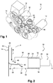
- FIG 1 represents an example of an accessory box 10 for the equipment drive 12 of a turbomachine such as a turbojet engine or an aircraft turboprop engine.
- a turbomachine such as a turbojet engine or an aircraft turboprop engine.
- Such a box of accessories is described in particular in the document FR-A1-2 941 744 .
- This accessory box 10 is intended to take mechanical power originating from the turbine engine and to transmit it to the equipment that is pumps, generators of electricity, etc.
- the transmission is performed by a kinematic chain composed of rotating elements geared to each other to form gear lines or accessories.
- the accessory box 10 comprises a casing 14 defining a housing for housing the rotating elements which comprise, for example, gears and bearings.
- the kinematic chain is connected to a drive shaft 16 which is a radial shaft of the turbomachine or an intermediate shaft, the chain being also connected to shafts 18 of power take-off equipment.
- the accessory box 10 is attached to the turbomachine and the equipment is in general itself attached to the accessory box 10.
- the figure 2 represents an embodiment of the invention.
- the reference numerals 10, 14 and 18 are also used to designate respectively the accessory box, its housing and the shaft of a equipment.
- the gearbox example according to the invention described with reference to Figures 2 to 4 relates to an accessory box, but it is understood that the embodiment described herein is also applicable to a transfer case.
- the coupling of the shaft 18 to the kinematic chain of the accessory box 10 is achieved by means of splines 24, 26.
- the shaft 18 comprises a male end portion 28 intended to be engaged in a sleeve 30 constituting a tubular portion of a rotating element or pinion of the accessory box, this end portion 28 having external or male grooves 24 which are preferably straight grooves extending substantially parallel to the axis A of rotation of the tree 18.
- Accessory box 10 includes one or more pinion sleeves 30, each sleeve serving to rotate a shaft 18 of equipment and to transmit the power of the driveline to that shaft.
- the sleeve 30 comprises a female end portion 32 intended to receive the end portion 28 of the shaft 18, this end portion 32 having internal or female grooves 26 substantially complementary to the grooves 24. They are therefore preferably rectilinear extending substantially parallel to the axis A of rotation of the shaft 18.
- the grooves 24, 26 here extend in an internal longitudinal cavity 34 of the sleeve 30 which is delimited at one end, located on the side of the shaft 18, by an annular seal 36 and at the opposite end by an annular dam 38
- the annular seal 36 is carried by the sleeve 30 and is intended to cooperate with the shaft 18 to ensure an oil seal between the sleeve 30 and the shaft 18.
- the seal 36 could be carried by the Shaft 18 and cooperate with the sleeve 30.
- the annular barrier 38 is preferably formed by a level annular seal.
- the cavity 34 makes it possible to store a determined volume of oil in which the grooves 24, 26.
- the level seal (barrier 38) is configured to define a maximum level of oil in the cavity 34, the excess oil then being discharged from the cavity 34 flowing through the seal level.
- the sleeve 30 is rotatable and rotated by at least one rotating element of the accessory box, for example another pinion.
- the sleeve may comprise at its outer periphery a toothed wheel adapted to be engaged with the toothed wheel of another pinion.
- the sleeve 30 and its gear wheel constitute a pinion.
- the rotating elements of the accessory box 10 are lubricated by oil which can be brought into the inner chamber of the housing 14 by nozzles for example.
- the accessory box 10 comprises means for recovering the lubricating oil from the rotating elements and the trickling of the recovered oil to the flutes 24, 26.
- These means here comprise a wall or a flange 42 of the housing 14 on which flows at least a portion of the oil which was used to lubricate the rotating elements.
- This flange 42 which serves as a sealing cover for the housing, comprises or carries at least one inner wall 48 for collecting lubricating oil from the rotating elements and a channeling member 44 which has an elongated shape and extends in part.
- the level seal (annular barrier 38) thus extends in a transverse plane P which is traversed by the channeling member 44.
- the run-off by the member 44 is provided sufficient to compensate for any minor oil leakage. at the joint 36.
- FIGS. 3 and 4 represent a more concrete example of embodiment of the accessory box 10 according to the invention and in particular of its flange 42 carrying the means for recovery and delivery of oil.
- the flange 42 is here formed in one piece and comprises in particular a flat portion on the inner face of which is formed at least one recess defining a collector inner wall 48 as described above.
- the flange 42 also comprises a hollow cylindrical portion 54 which extends substantially perpendicular to the flat portion and which supports a rolling bearing 52 of the sleeve.
- the internal collecting wall 48 is substantially perpendicular to the axis of this cylindrical portion 54.
- the rolling bearing 52 comprises an outer ring mounted in a free end portion of the cylindrical portion 54 and an inner ring mounted around a portion end of the sleeve 30, opposite the grooves 26.
- the sleeve 50 is thus partly engaged by an end portion in the cylindrical portion 54 of the flange 42. This end portion is however at axial distance from the portion plane flange 42 to allow an oil flow between them (arrow 46), as will be described in the following.
- the cylindrical portion 54 is here formed by a boss of the flange which comprises external radial extensions in which are provided threaded orifices 49 for screwing screws for fixing the outer ring of the bearing 52 to the flange 42.
- the cylindrical portion 54 comprises a radial opening 56 at the junction with the wall 48 of the flat portion of the flange 42. Oil can thus flow on the wall 48 to the inside of the cylindrical portion 54, passing through the opening 56.
- the flange 42 further comprises, radially inside the cylindrical portion 54, the aforementioned channeling member 44 as well as two gutters 50 which serve to collect the oil passing through the radial opening 56 and to route it to at the longitudinal end of the member 44 connected to the flat portion of the flange 42.
- Each channel 50 has a substantially U-shaped cross section and extends substantially radially with respect to the axis of the cylindrical portion 54, substantially from this axis to the cylindrical portion 54.
- the gutters 50 together form a V with a angle of the order of 120-160 °.
- the gutters 50 are located substantially in the axial space extending between the flat portion of the flange 42 and the end of the sleeve 30 guided by the bearing 52.
- the duct member 44 has a substantially U-shaped section and extends partially inside the sleeve 30 to be able to discharge the recovered oil into the inner cavity 34 of the sleeve.
- the cavity 34 is delimited by the level seal (dam 38) and by the aforementioned seal (seal 36 on the figure 2 ) which is here borne by the tree and is therefore not represented. This seal is intended to cooperate with an internal cylindrical surface of the sleeve 30.
- the end portion of the sleeve 30 having the splines 26 is guided by another bearing 60 and is further surrounded by a dynamic seal 62, the bearing 60 and the seal 62 being mounted in a cylindrical wall 64 of the housing 14 .
- the sleeve 30 is further secured to a wheel 66 with external teeth so as to form a pinion.
- the flask 42 of Figures 3 and 4 can be made of foundry for example, or by machining.
- the oil that is projected or discharges in operation on the collector wall 48 flows to the opening 56 and enters the cylindrical wall 54 to be collected in the gutters 50 which conveys this oil to the channel member 44.
- This oil then flows into the internal cavity 34 of the sleeve 30 for the lubrication of the grooves 26 as well as those of the corresponding equipment shaft. Since the channeling member 44 passes through the transverse plane in which the level seal (annular barrier 38) extends, the oil flows by gravitation to the free end of this channeling organ necessarily falls into the internal cavity 34 of the sleeve 30.
- the channeling member 44 is advantageously arranged to extend substantially horizontally once the accessory box is installed in the turbomachine, or to form a slight slope with respect to the horizontal in most flight attitudes so to promote the flow of oil by gravitation.
- the flow of the oil into the internal cavity 34 is not interrupted, except in exceptional flight attitudes and short duration. It may be provided for example that the opening of the sleeve 30 on the side of the gasket 38 is oriented towards the front of the aircraft, so that during flight the flow of the oil into the internal cavity 34 from the channeling member 44 can be interrupted only during a possible flight phase in steep downward inclination (especially in case of acceleration dive).
- the level gasket 38 advantageously has a radial height sufficient for stopping the turbomachine, that is to say when the rotating elements of the accessory box are no longer in rotation, a part of the grooves of the sleeve and the barbote shaft in the oil retained in the bottom of the internal cavity 34. At restart of the turbomachine, all the grooves are found quickly lubricated by the retained oil.
Landscapes
- Engineering & Computer Science (AREA)
- General Engineering & Computer Science (AREA)
- Mechanical Engineering (AREA)
- Chemical & Material Sciences (AREA)
- Combustion & Propulsion (AREA)
- General Details Of Gearings (AREA)
Applications Claiming Priority (2)
| Application Number | Priority Date | Filing Date | Title |
|---|---|---|---|
| FR1454679A FR3021358B1 (fr) | 2014-05-23 | 2014-05-23 | Boite d'engrenages de turbomachine d'aeronef |
| PCT/FR2015/051374 WO2015177487A1 (fr) | 2014-05-23 | 2015-05-22 | Boite d'engrenages de turbomachine d'aéronef |
Publications (2)
| Publication Number | Publication Date |
|---|---|
| EP3146183A1 EP3146183A1 (fr) | 2017-03-29 |
| EP3146183B1 true EP3146183B1 (fr) | 2018-02-14 |
Family
ID=51417437
Family Applications (1)
| Application Number | Title | Priority Date | Filing Date |
|---|---|---|---|
| EP15732796.6A Active EP3146183B1 (fr) | 2014-05-23 | 2015-05-22 | Boite d'engrenages de turbomachine d'aéronef |
Country Status (8)
| Country | Link |
|---|---|
| US (1) | US9790804B2 (https=) |
| EP (1) | EP3146183B1 (https=) |
| CN (1) | CN106460668B (https=) |
| BR (1) | BR112016027277B8 (https=) |
| CA (1) | CA2949818C (https=) |
| FR (1) | FR3021358B1 (https=) |
| RU (1) | RU2651004C1 (https=) |
| WO (1) | WO2015177487A1 (https=) |
Families Citing this family (25)
| Publication number | Priority date | Publication date | Assignee | Title |
|---|---|---|---|---|
| FR3059753B1 (fr) * | 2016-12-02 | 2019-10-25 | Renault S.A.S | Dispositif de guidage d'huile de lubrification a l'interieur d'un arbre creux de boite de vitesses |
| CN107237880B (zh) * | 2017-06-01 | 2019-04-30 | 中国航发湖南动力机械研究所 | 自动倾斜器导筒组件和主减速器 |
| US10883495B2 (en) | 2017-11-15 | 2021-01-05 | Hamilton Sundstrand Corporation | Scavenge/charge pump drive gear for integrated drive generator |
| US11306812B2 (en) * | 2018-09-28 | 2022-04-19 | Ge Avio S.R.L. | System and method for emergency lubricant flow at an aircraft gear assembly |
| FR3086974B1 (fr) | 2018-10-04 | 2021-01-08 | Safran Trans Systems | Boitier d'engrenages de turbomachine |
| FR3088979B1 (fr) * | 2018-11-23 | 2021-06-18 | Safran Trans Systems | Porte-satellites pour un reducteur mecanique de turbomachine d’aeronef |
| US10995675B2 (en) | 2019-02-19 | 2021-05-04 | Pratt & Whitney Canada Corp. | Gas turbine engine with accessory gearbox |
| FR3092885B1 (fr) * | 2019-02-20 | 2021-09-24 | Safran Trans Systems | Solaire pour un reducteur mecanique de turbomachine d’aeronef |
| FR3094406B1 (fr) | 2019-03-25 | 2021-03-05 | Safran Trans Systems | Pignon d’entrainement d’au moins un arbre d’accessoire pour un boitier d’accessoires de turbomachine d’aeronef |
| FR3095832B1 (fr) * | 2019-05-10 | 2021-05-21 | Safran Aircraft Engines | Système huile pour turbomachine |
| FR3096081B1 (fr) * | 2019-05-15 | 2021-04-23 | Safran Helicopter Engines | Pignon d’arbre de turbomachine à voile comportant une structure réticulée |
| FR3098548B1 (fr) * | 2019-07-08 | 2022-07-15 | Safran Trans Systems | Reducteur mecanique pour une turbomachine d’aeronef |
| CN110966052A (zh) * | 2019-12-02 | 2020-04-07 | 东方电气集团东方汽轮机有限公司 | 一种压缩机透平一体式机组及其运行方法 |
| CN112049924B (zh) * | 2020-09-07 | 2022-09-02 | 中国航发贵阳发动机设计研究所 | 一种重复利用滑油润滑结构 |
| US11661893B2 (en) | 2020-11-09 | 2023-05-30 | Ge Avio S.R.L. | Systems and methods of servicing turbomachines |
| JP7619132B2 (ja) | 2021-03-31 | 2025-01-22 | 株式会社アイシン | 回転電機及び車両駆動装置 |
| IT202100015386A1 (it) | 2021-06-11 | 2022-12-11 | Ge Avio Srl | Turbomacchine e gruppi ad ingranaggi epicicloidali con canali di lubrificazione |
| CN113803448B (zh) * | 2021-09-29 | 2025-11-07 | 广西玉柴机器股份有限公司 | 一种用于高速传动齿轮系的强制润滑结构 |
| CN115388157B (zh) * | 2022-05-13 | 2025-12-30 | 株洲九方装备股份有限公司 | 一种齿轮箱润滑系统及传动齿轮箱 |
| US12326115B2 (en) * | 2022-06-22 | 2025-06-10 | General Electric Company | Gearbox assembly with lubricant extraction volume ratio |
| US12421898B2 (en) | 2022-06-22 | 2025-09-23 | General Electric Company | Gearbox assembly with lubricant extraction volume ratio |
| US12320418B2 (en) * | 2022-06-22 | 2025-06-03 | General Electric Company | Gearbox assembly with lubricant extraction volume ratio |
| US12523176B2 (en) | 2022-06-22 | 2026-01-13 | General Electric Company | Gearbox assembly with lubricant extraction volume ratio |
| US12345201B2 (en) | 2022-06-22 | 2025-07-01 | General Electric Company | Gearbox assembly with lubricant extraction volume ratio |
| CN116576244A (zh) * | 2023-03-29 | 2023-08-11 | 中国航发湖南动力机械研究所 | 一种附件传动齿轮箱花键副的润滑装置 |
Family Cites Families (13)
| Publication number | Priority date | Publication date | Assignee | Title |
|---|---|---|---|---|
| GB1248437A (en) * | 1968-10-24 | 1971-10-06 | Rolls Royce | Lubrication system |
| JPS5455261A (en) * | 1977-10-12 | 1979-05-02 | Toyota Motor Corp | Lubricant induction unit for gear transmission |
| FR2649754B1 (fr) * | 1989-07-12 | 1991-11-29 | Hispano Suiza Sa | Dispositif de limitation de debit de lubrifiant au travers d'un arbre en rotation |
| US5119905A (en) | 1991-10-28 | 1992-06-09 | General Motors Corporation | Accessory drive spline lubrication system for a turbine engine reduction gear box |
| JP5053107B2 (ja) * | 2008-01-22 | 2012-10-17 | Gknドライブラインジャパン株式会社 | 動力伝達装置 |
| FR2929325B1 (fr) * | 2008-03-26 | 2012-09-28 | Snecma | Dispositif et procede d'equilibrage de pression dans une enceinte palier de turboreacteur |
| FR2941744B1 (fr) * | 2009-01-30 | 2011-09-16 | Hispano Suiza Sa | Ensemble d'un boitier de relais d'accessoires et d'un reservoir d'huile |
| JP5436111B2 (ja) * | 2009-09-16 | 2014-03-05 | 本田技研工業株式会社 | 潤滑油供給構造 |
| GB2488142B (en) * | 2011-02-17 | 2017-11-01 | Agustawestland Ltd | Tail rotor gearbox lubrication |
| FR2971816B1 (fr) * | 2011-02-21 | 2015-11-13 | Snecma | Arbre d'entrainement de boitier a engrenages de machines auxiliaires d'un turboreacteur |
| FR2989140B1 (fr) * | 2012-04-06 | 2014-09-05 | Snecma | Systeme de transmission de puissance pour une turbomachine |
| DE102012018603A1 (de) * | 2012-09-20 | 2014-03-20 | Rolls-Royce Deutschland Ltd & Co Kg | Hilfsgerätegetriebevorrichtung |
| US20140271142A1 (en) * | 2013-03-14 | 2014-09-18 | General Electric Company | Turbine Shroud with Spline Seal |
-
2014
- 2014-05-23 FR FR1454679A patent/FR3021358B1/fr active Active
-
2015
- 2015-05-22 BR BR112016027277A patent/BR112016027277B8/pt active IP Right Grant
- 2015-05-22 WO PCT/FR2015/051374 patent/WO2015177487A1/fr not_active Ceased
- 2015-05-22 US US15/313,036 patent/US9790804B2/en active Active
- 2015-05-22 CA CA2949818A patent/CA2949818C/fr active Active
- 2015-05-22 CN CN201580026913.3A patent/CN106460668B/zh active Active
- 2015-05-22 EP EP15732796.6A patent/EP3146183B1/fr active Active
- 2015-05-22 RU RU2016148457A patent/RU2651004C1/ru active
Also Published As
| Publication number | Publication date |
|---|---|
| RU2651004C1 (ru) | 2018-04-18 |
| FR3021358A1 (fr) | 2015-11-27 |
| CN106460668A (zh) | 2017-02-22 |
| BR112016027277B1 (pt) | 2022-01-25 |
| CN106460668B (zh) | 2018-05-22 |
| BR112016027277B8 (pt) | 2022-04-19 |
| WO2015177487A1 (fr) | 2015-11-26 |
| BR112016027277A2 (https=) | 2017-08-15 |
| FR3021358B1 (fr) | 2018-07-20 |
| EP3146183A1 (fr) | 2017-03-29 |
| CA2949818A1 (fr) | 2015-11-26 |
| CA2949818C (fr) | 2018-04-03 |
| US9790804B2 (en) | 2017-10-17 |
| US20170138214A1 (en) | 2017-05-18 |
Similar Documents
| Publication | Publication Date | Title |
|---|---|---|
| EP3146183B1 (fr) | Boite d'engrenages de turbomachine d'aéronef | |
| EP3495692B1 (fr) | Couronne de reducteur de vitesse a train planetaire de turbomachine | |
| EP3575562B1 (fr) | Système de transmission de puissance comprenant un dispositif de récupération d'huile de lubrification et turbomachine équipée d'un tel système de transmission de puissance | |
| EP3350482B1 (fr) | Dispositif d'alimentation en huile pour un reducteur a train epicycloïdal | |
| EP3137741B1 (fr) | Turbomachine d'aéronef a prélèvement de puissance mécanique amélioré | |
| FR3073915A1 (fr) | Cage de reducteur de vitesse a train planetaire ou epicycloidal de turbomachine | |
| EP3956555B1 (fr) | Reducteur de vitesse d'une turbomachine | |
| EP3247924B1 (fr) | Intégration d'une pompe en fût de pignon | |
| FR2987416A1 (fr) | Dispositif de lubrification d'un reducteur epicycloidal. | |
| EP3857029B1 (fr) | Reservoir auxiliaire d'huile pour une turbomachine d'aeronef | |
| FR2995055A1 (fr) | Reducteur a train epicycloidal, notamment pour turbomachine | |
| WO2015166178A1 (fr) | Assemblage pour turbomachine d'aéronef et son procédé de montage | |
| FR2987402A1 (fr) | Dispositif de lubrification d'un reducteur epicycloidal compatible d'un montage modulaire. | |
| CA2952506A1 (fr) | Dispositif et procede de lubrification d'un palier a roulement de turbomachine | |
| FR3075868B1 (fr) | Tube de degazage pour une turbomachine d'aeronef a reducteur | |
| EP3262283B1 (fr) | Palier hydrodynamique | |
| EP3610177B1 (fr) | Train d'engrenages epicycloïdal | |
| WO2018189442A1 (fr) | Lubrification pour train d'engrenages épicycloïdal | |
| FR3106155A1 (fr) | Système de lubrification d’engrenages pour une turbomachine d’aéronef | |
| FR3086974A1 (fr) | Boitier d'engrenages de turbomachine | |
| FR3099220A1 (fr) | Réducteur de vitesse à train épicycloïdal pour une turbomachine | |
| FR3156828A1 (fr) | Ensemble pour une turbomachine d’aeronef comprenant un reducteur et un systeme de lubrification du reducteur | |
| FR3088683A1 (fr) | Ensemble pour turbomachine d'aeronef comportant un systeme a lubrifier ainsi qu'un dispositif ameliore d'injection de lubrifiant |
Legal Events
| Date | Code | Title | Description |
|---|---|---|---|
| PUAI | Public reference made under article 153(3) epc to a published international application that has entered the european phase |
Free format text: ORIGINAL CODE: 0009012 |
|
| 17P | Request for examination filed |
Effective date: 20161130 |
|
| AK | Designated contracting states |
Kind code of ref document: A1 Designated state(s): AL AT BE BG CH CY CZ DE DK EE ES FI FR GB GR HR HU IE IS IT LI LT LU LV MC MK MT NL NO PL PT RO RS SE SI SK SM TR |
|
| AX | Request for extension of the european patent |
Extension state: BA ME |
|
| DAV | Request for validation of the european patent (deleted) | ||
| DAX | Request for extension of the european patent (deleted) | ||
| GRAP | Despatch of communication of intention to grant a patent |
Free format text: ORIGINAL CODE: EPIDOSNIGR1 |
|
| INTG | Intention to grant announced |
Effective date: 20170921 |
|
| GRAS | Grant fee paid |
Free format text: ORIGINAL CODE: EPIDOSNIGR3 |
|
| GRAA | (expected) grant |
Free format text: ORIGINAL CODE: 0009210 |
|
| AK | Designated contracting states |
Kind code of ref document: B1 Designated state(s): AL AT BE BG CH CY CZ DE DK EE ES FI FR GB GR HR HU IE IS IT LI LT LU LV MC MK MT NL NO PL PT RO RS SE SI SK SM TR |
|
| REG | Reference to a national code |
Ref country code: GB Ref legal event code: FG4D Free format text: NOT ENGLISH |
|
| REG | Reference to a national code |
Ref country code: CH Ref legal event code: EP |
|
| REG | Reference to a national code |
Ref country code: IE Ref legal event code: FG4D Free format text: LANGUAGE OF EP DOCUMENT: FRENCH |
|
| REG | Reference to a national code |
Ref country code: DE Ref legal event code: R096 Ref document number: 602015008052 Country of ref document: DE Ref country code: AT Ref legal event code: REF Ref document number: 969993 Country of ref document: AT Kind code of ref document: T Effective date: 20180315 |
|
| REG | Reference to a national code |
Ref country code: SE Ref legal event code: TRGR |
|
| REG | Reference to a national code |
Ref country code: FR Ref legal event code: PLFP Year of fee payment: 4 |
|
| REG | Reference to a national code |
Ref country code: NL Ref legal event code: MP Effective date: 20180214 |
|
| REG | Reference to a national code |
Ref country code: AT Ref legal event code: MK05 Ref document number: 969993 Country of ref document: AT Kind code of ref document: T Effective date: 20180214 |
|
| PG25 | Lapsed in a contracting state [announced via postgrant information from national office to epo] |
Ref country code: NO Free format text: LAPSE BECAUSE OF FAILURE TO SUBMIT A TRANSLATION OF THE DESCRIPTION OR TO PAY THE FEE WITHIN THE PRESCRIBED TIME-LIMIT Effective date: 20180514 Ref country code: LT Free format text: LAPSE BECAUSE OF FAILURE TO SUBMIT A TRANSLATION OF THE DESCRIPTION OR TO PAY THE FEE WITHIN THE PRESCRIBED TIME-LIMIT Effective date: 20180214 Ref country code: FI Free format text: LAPSE BECAUSE OF FAILURE TO SUBMIT A TRANSLATION OF THE DESCRIPTION OR TO PAY THE FEE WITHIN THE PRESCRIBED TIME-LIMIT Effective date: 20180214 Ref country code: NL Free format text: LAPSE BECAUSE OF FAILURE TO SUBMIT A TRANSLATION OF THE DESCRIPTION OR TO PAY THE FEE WITHIN THE PRESCRIBED TIME-LIMIT Effective date: 20180214 Ref country code: CY Free format text: LAPSE BECAUSE OF FAILURE TO SUBMIT A TRANSLATION OF THE DESCRIPTION OR TO PAY THE FEE WITHIN THE PRESCRIBED TIME-LIMIT Effective date: 20180214 Ref country code: ES Free format text: LAPSE BECAUSE OF FAILURE TO SUBMIT A TRANSLATION OF THE DESCRIPTION OR TO PAY THE FEE WITHIN THE PRESCRIBED TIME-LIMIT Effective date: 20180214 Ref country code: HR Free format text: LAPSE BECAUSE OF FAILURE TO SUBMIT A TRANSLATION OF THE DESCRIPTION OR TO PAY THE FEE WITHIN THE PRESCRIBED TIME-LIMIT Effective date: 20180214 |
|
| PG25 | Lapsed in a contracting state [announced via postgrant information from national office to epo] |
Ref country code: RS Free format text: LAPSE BECAUSE OF FAILURE TO SUBMIT A TRANSLATION OF THE DESCRIPTION OR TO PAY THE FEE WITHIN THE PRESCRIBED TIME-LIMIT Effective date: 20180214 Ref country code: BG Free format text: LAPSE BECAUSE OF FAILURE TO SUBMIT A TRANSLATION OF THE DESCRIPTION OR TO PAY THE FEE WITHIN THE PRESCRIBED TIME-LIMIT Effective date: 20180514 Ref country code: AT Free format text: LAPSE BECAUSE OF FAILURE TO SUBMIT A TRANSLATION OF THE DESCRIPTION OR TO PAY THE FEE WITHIN THE PRESCRIBED TIME-LIMIT Effective date: 20180214 Ref country code: LV Free format text: LAPSE BECAUSE OF FAILURE TO SUBMIT A TRANSLATION OF THE DESCRIPTION OR TO PAY THE FEE WITHIN THE PRESCRIBED TIME-LIMIT Effective date: 20180214 Ref country code: GR Free format text: LAPSE BECAUSE OF FAILURE TO SUBMIT A TRANSLATION OF THE DESCRIPTION OR TO PAY THE FEE WITHIN THE PRESCRIBED TIME-LIMIT Effective date: 20180515 |
|
| PG25 | Lapsed in a contracting state [announced via postgrant information from national office to epo] |
Ref country code: MT Free format text: LAPSE BECAUSE OF FAILURE TO SUBMIT A TRANSLATION OF THE DESCRIPTION OR TO PAY THE FEE WITHIN THE PRESCRIBED TIME-LIMIT Effective date: 20180214 |
|
| PG25 | Lapsed in a contracting state [announced via postgrant information from national office to epo] |
Ref country code: PL Free format text: LAPSE BECAUSE OF FAILURE TO SUBMIT A TRANSLATION OF THE DESCRIPTION OR TO PAY THE FEE WITHIN THE PRESCRIBED TIME-LIMIT Effective date: 20180214 Ref country code: RO Free format text: LAPSE BECAUSE OF FAILURE TO SUBMIT A TRANSLATION OF THE DESCRIPTION OR TO PAY THE FEE WITHIN THE PRESCRIBED TIME-LIMIT Effective date: 20180214 Ref country code: EE Free format text: LAPSE BECAUSE OF FAILURE TO SUBMIT A TRANSLATION OF THE DESCRIPTION OR TO PAY THE FEE WITHIN THE PRESCRIBED TIME-LIMIT Effective date: 20180214 Ref country code: AL Free format text: LAPSE BECAUSE OF FAILURE TO SUBMIT A TRANSLATION OF THE DESCRIPTION OR TO PAY THE FEE WITHIN THE PRESCRIBED TIME-LIMIT Effective date: 20180214 |
|
| REG | Reference to a national code |
Ref country code: DE Ref legal event code: R097 Ref document number: 602015008052 Country of ref document: DE |
|
| PG25 | Lapsed in a contracting state [announced via postgrant information from national office to epo] |
Ref country code: CZ Free format text: LAPSE BECAUSE OF FAILURE TO SUBMIT A TRANSLATION OF THE DESCRIPTION OR TO PAY THE FEE WITHIN THE PRESCRIBED TIME-LIMIT Effective date: 20180214 Ref country code: SK Free format text: LAPSE BECAUSE OF FAILURE TO SUBMIT A TRANSLATION OF THE DESCRIPTION OR TO PAY THE FEE WITHIN THE PRESCRIBED TIME-LIMIT Effective date: 20180214 Ref country code: SM Free format text: LAPSE BECAUSE OF FAILURE TO SUBMIT A TRANSLATION OF THE DESCRIPTION OR TO PAY THE FEE WITHIN THE PRESCRIBED TIME-LIMIT Effective date: 20180214 Ref country code: DK Free format text: LAPSE BECAUSE OF FAILURE TO SUBMIT A TRANSLATION OF THE DESCRIPTION OR TO PAY THE FEE WITHIN THE PRESCRIBED TIME-LIMIT Effective date: 20180214 |
|
| REG | Reference to a national code |
Ref country code: CH Ref legal event code: PL |
|
| PLBE | No opposition filed within time limit |
Free format text: ORIGINAL CODE: 0009261 |
|
| STAA | Information on the status of an ep patent application or granted ep patent |
Free format text: STATUS: NO OPPOSITION FILED WITHIN TIME LIMIT |
|
| 26N | No opposition filed |
Effective date: 20181115 |
|
| REG | Reference to a national code |
Ref country code: BE Ref legal event code: MM Effective date: 20180531 |
|
| PG25 | Lapsed in a contracting state [announced via postgrant information from national office to epo] |
Ref country code: MC Free format text: LAPSE BECAUSE OF FAILURE TO SUBMIT A TRANSLATION OF THE DESCRIPTION OR TO PAY THE FEE WITHIN THE PRESCRIBED TIME-LIMIT Effective date: 20180214 |
|
| REG | Reference to a national code |
Ref country code: IE Ref legal event code: MM4A |
|
| PG25 | Lapsed in a contracting state [announced via postgrant information from national office to epo] |
Ref country code: SI Free format text: LAPSE BECAUSE OF FAILURE TO SUBMIT A TRANSLATION OF THE DESCRIPTION OR TO PAY THE FEE WITHIN THE PRESCRIBED TIME-LIMIT Effective date: 20180214 Ref country code: LI Free format text: LAPSE BECAUSE OF NON-PAYMENT OF DUE FEES Effective date: 20180531 Ref country code: CH Free format text: LAPSE BECAUSE OF NON-PAYMENT OF DUE FEES Effective date: 20180531 |
|
| PG25 | Lapsed in a contracting state [announced via postgrant information from national office to epo] |
Ref country code: LU Free format text: LAPSE BECAUSE OF NON-PAYMENT OF DUE FEES Effective date: 20180522 |
|
| PG25 | Lapsed in a contracting state [announced via postgrant information from national office to epo] |
Ref country code: IE Free format text: LAPSE BECAUSE OF NON-PAYMENT OF DUE FEES Effective date: 20180522 |
|
| PG25 | Lapsed in a contracting state [announced via postgrant information from national office to epo] |
Ref country code: BE Free format text: LAPSE BECAUSE OF NON-PAYMENT OF DUE FEES Effective date: 20180531 |
|
| PG25 | Lapsed in a contracting state [announced via postgrant information from national office to epo] |
Ref country code: TR Free format text: LAPSE BECAUSE OF FAILURE TO SUBMIT A TRANSLATION OF THE DESCRIPTION OR TO PAY THE FEE WITHIN THE PRESCRIBED TIME-LIMIT Effective date: 20180214 |
|
| PG25 | Lapsed in a contracting state [announced via postgrant information from national office to epo] |
Ref country code: PT Free format text: LAPSE BECAUSE OF FAILURE TO SUBMIT A TRANSLATION OF THE DESCRIPTION OR TO PAY THE FEE WITHIN THE PRESCRIBED TIME-LIMIT Effective date: 20180214 |
|
| PG25 | Lapsed in a contracting state [announced via postgrant information from national office to epo] |
Ref country code: HU Free format text: LAPSE BECAUSE OF FAILURE TO SUBMIT A TRANSLATION OF THE DESCRIPTION OR TO PAY THE FEE WITHIN THE PRESCRIBED TIME-LIMIT; INVALID AB INITIO Effective date: 20150522 Ref country code: MK Free format text: LAPSE BECAUSE OF NON-PAYMENT OF DUE FEES Effective date: 20180214 |
|
| PG25 | Lapsed in a contracting state [announced via postgrant information from national office to epo] |
Ref country code: IS Free format text: LAPSE BECAUSE OF FAILURE TO SUBMIT A TRANSLATION OF THE DESCRIPTION OR TO PAY THE FEE WITHIN THE PRESCRIBED TIME-LIMIT Effective date: 20180614 |
|
| PGFP | Annual fee paid to national office [announced via postgrant information from national office to epo] |
Ref country code: DE Payment date: 20250519 Year of fee payment: 11 |
|
| PGFP | Annual fee paid to national office [announced via postgrant information from national office to epo] |
Ref country code: GB Payment date: 20250527 Year of fee payment: 11 |
|
| PGFP | Annual fee paid to national office [announced via postgrant information from national office to epo] |
Ref country code: IT Payment date: 20250530 Year of fee payment: 11 |
|
| PGFP | Annual fee paid to national office [announced via postgrant information from national office to epo] |
Ref country code: FR Payment date: 20250526 Year of fee payment: 11 |
|
| PGFP | Annual fee paid to national office [announced via postgrant information from national office to epo] |
Ref country code: SE Payment date: 20250522 Year of fee payment: 11 |