EP3145461B1 - Push-to-fit earplug having an array of cavities - Google Patents
Push-to-fit earplug having an array of cavities Download PDFInfo
- Publication number
- EP3145461B1 EP3145461B1 EP15725161.2A EP15725161A EP3145461B1 EP 3145461 B1 EP3145461 B1 EP 3145461B1 EP 15725161 A EP15725161 A EP 15725161A EP 3145461 B1 EP3145461 B1 EP 3145461B1
- Authority
- EP
- European Patent Office
- Prior art keywords
- earplug
- cavities
- array
- stem
- cavity
- Prior art date
- Legal status (The legal status is an assumption and is not a legal conclusion. Google has not performed a legal analysis and makes no representation as to the accuracy of the status listed.)
- Active
Links
Images


Classifications
-
- A—HUMAN NECESSITIES
- A61—MEDICAL OR VETERINARY SCIENCE; HYGIENE
- A61F—FILTERS IMPLANTABLE INTO BLOOD VESSELS; PROSTHESES; DEVICES PROVIDING PATENCY TO, OR PREVENTING COLLAPSING OF, TUBULAR STRUCTURES OF THE BODY, e.g. STENTS; ORTHOPAEDIC, NURSING OR CONTRACEPTIVE DEVICES; FOMENTATION; TREATMENT OR PROTECTION OF EYES OR EARS; BANDAGES, DRESSINGS OR ABSORBENT PADS; FIRST-AID KITS
- A61F11/00—Methods or devices for treatment of the ears or hearing sense; Non-electric hearing aids; Methods or devices for enabling ear patients to achieve auditory perception through physiological senses other than hearing sense; Protective devices for the ears, carried on the body or in the hand
- A61F11/06—Protective devices for the ears
- A61F11/08—Protective devices for the ears internal, e.g. earplugs
- A61F11/085—Protective devices for the ears internal, e.g. earplugs including an inner channel
-
- A—HUMAN NECESSITIES
- A61—MEDICAL OR VETERINARY SCIENCE; HYGIENE
- A61F—FILTERS IMPLANTABLE INTO BLOOD VESSELS; PROSTHESES; DEVICES PROVIDING PATENCY TO, OR PREVENTING COLLAPSING OF, TUBULAR STRUCTURES OF THE BODY, e.g. STENTS; ORTHOPAEDIC, NURSING OR CONTRACEPTIVE DEVICES; FOMENTATION; TREATMENT OR PROTECTION OF EYES OR EARS; BANDAGES, DRESSINGS OR ABSORBENT PADS; FIRST-AID KITS
- A61F2230/00—Geometry of prostheses classified in groups A61F2/00 - A61F2/26 or A61F2/82 or A61F9/00 or A61F11/00 or subgroups thereof
- A61F2230/0002—Two-dimensional shapes, e.g. cross-sections
- A61F2230/0017—Angular shapes
- A61F2230/0023—Angular shapes triangular
-
- A—HUMAN NECESSITIES
- A61—MEDICAL OR VETERINARY SCIENCE; HYGIENE
- A61F—FILTERS IMPLANTABLE INTO BLOOD VESSELS; PROSTHESES; DEVICES PROVIDING PATENCY TO, OR PREVENTING COLLAPSING OF, TUBULAR STRUCTURES OF THE BODY, e.g. STENTS; ORTHOPAEDIC, NURSING OR CONTRACEPTIVE DEVICES; FOMENTATION; TREATMENT OR PROTECTION OF EYES OR EARS; BANDAGES, DRESSINGS OR ABSORBENT PADS; FIRST-AID KITS
- A61F2230/00—Geometry of prostheses classified in groups A61F2/00 - A61F2/26 or A61F2/82 or A61F9/00 or A61F11/00 or subgroups thereof
- A61F2230/0002—Two-dimensional shapes, e.g. cross-sections
- A61F2230/0028—Shapes in the form of latin or greek characters
- A61F2230/005—Rosette-shaped, e.g. star-shaped
-
- A—HUMAN NECESSITIES
- A61—MEDICAL OR VETERINARY SCIENCE; HYGIENE
- A61F—FILTERS IMPLANTABLE INTO BLOOD VESSELS; PROSTHESES; DEVICES PROVIDING PATENCY TO, OR PREVENTING COLLAPSING OF, TUBULAR STRUCTURES OF THE BODY, e.g. STENTS; ORTHOPAEDIC, NURSING OR CONTRACEPTIVE DEVICES; FOMENTATION; TREATMENT OR PROTECTION OF EYES OR EARS; BANDAGES, DRESSINGS OR ABSORBENT PADS; FIRST-AID KITS
- A61F2250/00—Special features of prostheses classified in groups A61F2/00 - A61F2/26 or A61F2/82 or A61F9/00 or A61F11/00 or subgroups thereof
- A61F2250/0014—Special features of prostheses classified in groups A61F2/00 - A61F2/26 or A61F2/82 or A61F9/00 or A61F11/00 or subgroups thereof having different values of a given property or geometrical feature, e.g. mechanical property or material property, at different locations within the same prosthesis
- A61F2250/0036—Special features of prostheses classified in groups A61F2/00 - A61F2/26 or A61F2/82 or A61F9/00 or A61F11/00 or subgroups thereof having different values of a given property or geometrical feature, e.g. mechanical property or material property, at different locations within the same prosthesis differing in thickness
Definitions
- This disclosure relates to a hearing protection device, in particular a push-to-fit earplug having a tip region and an array of cavities positioned in the tip region and spaced around the longitudinal axis that provide a collapsible volume.
- hearing protective and noise attenuating devices are well known, and various types of devices have been considered.
- Such devices include earplugs and semi-aural devices partially or completely constructed of foam or rubber materials that are inserted into, or placed over, the ear canal of a user to physically obstruct the passage of sound waves into the inner ear.
- Compressible or "roll-down" type earplugs generally comprise a compressible, resilient body portion and may be made of suitable slow recovery foam materials.
- the earplug may be inserted into the ear canal of a user by first rolling it between fingers to compress the body portion, then pushing the body portion into the ear canal, and subsequently allowing the body portion to expand to fill the ear canal.
- Push-to-fit type earplugs have also been considered, and may include a compressible attenuating portion and a stiff portion that extends from the attenuating portion.
- US 2005/274568 discloses a hearing protection device insertable into an earcanal, the device generally including a stem portion, a sound attenuating portion affixed to and extending at least partially over the stem portion, and a volume of space disposed between and delimited by the sound attenuating portion and the stem portion, where at least a part of the sound attenuating portion is collapsible into the volume of space during insertion of the hearing protection device into the earcanal.
- Push-to-fit earplugs may allow the earplug to be quickly and easily inserted in an ear canal, and may promote hygiene by minimizing contact with the attenuating portion of the earplug prior to insertion.
- an earplug such as a push-to-fit earplug.
- an earplug includes a stem and a sound attenuating body attached to the stem.
- the sound attenuating body includes a leading end, a base end, a tip region positioned rearward of the leading end, and a longitudinal axis extending between the leading end and the base end.
- An array of cavities is positioned within the tip region and spaced around the longitudinal axis, and the array of cavities provides a collapsible volume.
- the tip region comprises a cavity area (Ac), a material area (Am) and an area aspect ratio (Ac/Am) at a plane intersecting the array of cavities transverse to the longitudinal axis, and 0.10 ⁇ (Ac/Am) ⁇ 0.35.
- the sound attenuating body further includes a flange extending at least partially over the stem and comprising an exterior flange surface and an interior flange surface having a plurality of one or both of protrusions or recesses and the earplug further includes a flange cavity including a continuous volume around a perimeter of the stem between the interior flange surface and the stem.
- An earplug that provides hearing protection for a user is provided herein.
- An earplug according to the present disclosure includes a stem and a sound attenuating body having a flange. When inserted into the ear canal of a user, the sound attenuating body is able to compress and at least partially collapse into a collapsible volume provided by an array of cavities in a tip region. The array of cavities provide additional volume into which a portion of the sound attenuating body can collapse, reducing an insertion force required to position the earplug in an ear canal and reducing an equilibrium force exerted by the earplug and acting on a user's ear canal when the earplug is positioned for use.
- An earplug having an array of cavities in a tip region as described herein facilitates an earplug that is easy to insert and comfortable to wear.
- FIGS. 1 through 3 show an exemplary push-to-fit earplug 100 including a stem 110 and sound attenuating body 120 and having first and second ends 101 and 102.
- Sound attenuating body 120 is configured for at least partial insertion into the ear canal of a user to attenuate the passage of sound into the ear canal.
- stem 110 may serve as a handle which may be gripped by a user.
- Earplug 100, and specifically sound attenuating body 120 is brought proximate to the user's ear and at least partially inserted into the ear canal. Sound attenuating body 120 compresses and/or collapses as it is positioned, and stem 110 provides sufficient stiffness to facilitate insertion.
- sound attenuating body 120 is positioned substantially within an ear canal to block the passage of sound and stem 110 extends outwardly from the ear canal to provide a handle to remove the earplug.
- sound attenuating body 120 includes a leading end 121, a base end 122, a tip region 123 and a flange 124 extending at least partially over stem 110. Tip region 123 is located rearwardly of leading end 121 and flange 124 is located between tip region 123 and base end 122.
- sound attenuating body 120 defines a flange cavity 130 between stem 110 and sound attenuating body 120.
- flange cavity 130 is defined at least in part by stem 110, sound attenuating body 120, and a flange cavity bottom 131.
- Flange cavity bottom 131 may be formed by a portion of tip region 123, where stem 110 and sound attenuating body 120 intersect, for example.
- a longitudinal axis 10 extends between leading end 121 and base end 122 of sound attenuating body 120.
- a leading end plane 11 passes across an outermost tip of leading end 121, and/or first end 101, of earplug 100 transverse to the longitudinal axis, and a flange end plane 15 intersects earplug 100 transverse to longitudinal axis 10 at base end 122 of flange 124.
- a cavity plane 13 intersects earplug 100 at a forward-most portion of flange cavity 130.
- flange 124 is not attached to stem 110 within flange cavity 130, or between cavity plane 13 and base end 122, and only attaches to stem at and/or above cavity plane 13.
- Flange 124 may be defined as that portion of sound attenuating body 120 that is located below the cavity plane 13. Because flange 124 is connected to a remainder of sound attenuating body 120 and/or stem 110 only near one end, flange cavity 130 includes a continuous volume around stem 110. According to the invention, an interior flange surface 126 of flange 124 does not contact stem 110 when in a neutral, uncompressed configuration such as when not positioned in an ear canal.
- the flange cavity includes a continuous uninterrupted volume around a perimeter of at least a portion of stem 110.
- Flange 124 may deflect inwardly as earplug 100 is advanced into an ear canal and/or is positioned therein, and in some embodiments interior flange surface 126 may at least partially contact stem 110.
- deflection and/or compression of flange 124 may improve insertion, comfort, and sound attenuation, and may be controlled by the materials, geometry, and configuration of earplug 100.
- Earplug 100 includes an array of cavities 160 positioned within tip region 123 and spaced around the longitudinal axis 10. Cavities 160 provide a collapsible volume that at least a portion of sound attenuating body 120 may collapse into as earplug 100 is advanced into an ear canal of a user. Collapsible volume provided by cavities 160 provides an earplug 100 that may be comfortably inserted and worn by a user while providing a desired level of sound attenuation.
- the geometry and configuration of cavities 160 may be selected as described herein to provide a desire balance of fit for a range of users having varied ear canal shapes and sizes.
- Cavities 160 may be positioned around longitudinal axis 10 and extend within tip region 123 of earplug 100.
- earplug 100 includes a flange cavity 130 between stem 110 and sound attenuating body 120 and having a flange cavity bottom 131. Cavities 160 are positioned between flange cavity bottom 131 and leading end 121 of sound attenuating body 120 (e.g. between cavity plane 13 and leading end plane 11).
- the array of cavities 160 extend between first and second cavity ends 161 and 162 and have a generally elongate shape.
- First cavity end 161 may be the forward-most portion of array of cavities 160 nearest to leading end 121 and second cavity end 162 may be the rearward-most portion of array of cavities 160 furthest from leading end 121.
- cavities 160 have a length (Lc) between first and second cavity ends 161 and 162 between about 1.0 mm and 6.0 mm, 2.0 mm and 5.0 mm, or of about 4.0 mm.
- first cavity end 161 is between 3.5 mm and 8.0 mm, 4.5 mm and 7.3 mm, or about 5.5 mm from leading end 121 of sound attenuating body 120. Such a distance allows for sufficient stiffness such that leading end 121 may be readily inserted into a user's ear.
- Second cavity end 162 is at least partially open and in communication with flange cavity 130, and second cavity end 162 may be located proximate cavity plane 13.
- Array of cavities 160 are sized to provide a desirable collapsible space to reduce a force required to compress sound attenuating body 120 when earplug 100 is at least partially inserted into an ear canal of a user.
- tip region 123 of sound attenuating body 120 may be characterized as having a cavity area (Ac) and a material area (Am) at a plane intersecting array of cavities 160 transverse to the longitudinal axis, such as plane 12.
- Cavity area (Ac) is an area of open space within each cavity 160
- material area (Am) is the remaining area of tip region 123 of earplug 100 including material, such as foam material and cells that may be present in the material.
- cavity area (Ac) may be between 4 mm 2 and 36 mm 2 , 6 mm 2 and 24 mm 2 , or about 12 mm 2
- material area (Am) may be about 45 mm 2 to 65 mm 2 , 50 mm 2 to 60 mm 2 , or about 55 mm 2 .
- array of cavities 160 exhibits an area aspect ratio (Ac/Am) of cavity area (Ac) to material area (Am).
- (Ac/Am) is between 0.04 and 0.35, 0.10 and 0.30, or about 0.22, and in some exemplary embodiments may exhibit an area aspect ratio (Ac/Am) within such ranges when plane 12 passes through array of cavities at a distance between 4.5 mm and 8.0 mm from leading end 121.
- a maximum area aspect ratio (Ac/Am) exists at a plane passing through array of cavities transverse to longitudinal axis 10 at a location in which (Ac/Am) is greatest.
- maximum area aspect ratio (Ac/Am) at plane 12 intersecting array of cavities 160 at a distance between 7.0 mm and 10.0 mm is between 0.10 and 0.35, 0.16 and 0.28, or about 0.22.
- maximum area aspect ratio (Ac/Am) occurs at second end 162, for example at cavity plane 13, and the cavities taper such that (Ac/Am) decreases at locations closer to first end 161 of array of cavities 160.
- Reduced wall thickness (Tw) may be selected to provide a required level of durability such that earplug does not readily tear or break while also not being so thick so as to unduly increase equilibrium force.
- reduced wall thickness is between 1.0 mm and 2.5 mm, 1.1 mm and 1.7 mm, or about 1.25 mm.
- An exemplary earplug 100 having dimensions and cavity area (Ac) within the above ranges provides additional collapsible space for material of tip region 123 to compress into as tip region 123 is positioned and resident in an ear canal of a user.
- such ranges may result in a desired equilibrium force exerted by tip region 123 when residing in an ear canal of a user.
- Equilibrium force is a force exerted by earplug 100 to return to an original, uncompressed state and is related to a force exerted on a user's ear canal when earplug 100 is positioned for use.
- array of cavities 160 having a cavity area (Ac) within such ranges provides a reduced equilibrium force to maximize comfort while ensuring sufficient force that earplug 100 may be maintained in position in a user's ear canal.
- array of cavities 160 can reduce equilibrium force between 5 % and 50 %, 10 % and 40 %, or about 25 % as compared to an earplug having the same material and geometry but not having an array of cavities.
- Array of cavities 160 may include any suitable number and shape of cavities.
- array of cavities 160 includes between 4 and 24, 6 and 18, or about 8 cavities 160.
- Cavities 160 may have any desired cross-sectional shape and may vary along a length of the cavities, for example between first and second cavity ends 161, 162.
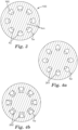
- cavities 160 have a generally trapezoidal shape, and is only one example of many suitable shapes for cavities as described herein.
- Other exemplary shapes include, but are not limited to, the shapes of Figs. 4a and 4b.
- Figure 4a and 4b show earplugs 201 and 202 having an array of cavities 261, 262 that exhibit oval, or otherwise arcuate, and quadrilateral cavities.
- An exemplary earplug as described herein may have any suitable shape or profile to provide a desired fit or that may be suitable for a particular application.
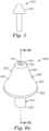
- the specific shape of sound attenuating body 120 of the exemplary embodiment depicted in FIGS. 1 through 3 is only one example of a potentially suitable shape for an earplug as described herein. Examples of one of the myriad of alternative shapes that could be used for earplugs as described herein is depicted in FIG. 5 showing exemplary earplug 500 having sound attenuating body 521.
- a channel 113 extends through earplug 100 between first and second ends 101, 102.
- Earplugs as described herein that include channels passing through the earplug may be manufactured such that components of a receiver or of a communication system may be attached to the earplug.
- channel 113 may accommodate one or more filters or other passive hearing elements to provide an attenuation curve having a desired shape.
- filters positioned in channel 113 may cause nonlinear attenuation of high level impulses produced by explosions, gunfire, or the like.
- Channels provided in one or more embodiments of earplugs as described herein may also provide a recess that a cord may be attached to, such that first and second earplugs may be joined, or that ends of a headband may be attached to in a semi-aural hearing protector.
- earplug 100 includes a core 140 that provides a substrate onto which an outer layer of material may be provided and, in one or more embodiments, may facilitate insertion into an ear canal of a user.
- Core 140 is made of a first material that exhibits greater rigidity or stiffness than a second material that forms sound attenuating body 120, yet that is soft enough to be comfortable and safe for a user.
- the first material of core 140 is different than the second material used to form sound attenuating body 120 and/or an outer layer 115 of stem 110.
- the first and second materials are similar or the same chemically, but may be formed or provided in a manner that results in different stiffnesses between the first material and the second material, for example due to differing density, cell structure, hardness, etc.
- Including a core 140 in the stem 110 that is stiffer than the material of sound attenuating body 120 and/or outer layer 115 of the stem 110 may, in one or more exemplary embodiments, provide a stem 110 having sufficient rigidity so that the earplugs described herein may be positioned for use at least partially in the ear of a user by pushing sound attenuating body 120 into the ear canal with an appropriate force. That is, a sufficiently stiff stem 110 may be provided by a core 140 and an outer layer 115 of the material used to form the sound attenuating body 120 so that earplug 100 may be positioned for use at least partially in the ear of a user without the need to first compress or "roll down" sound attenuating body 120.
- Direct insertion without the need to first compress or "roll down" sound attenuating body 120 may, for example, promote hygiene by limiting contact with sound attenuating body 120 prior to placement in the ear.
- core 140 may also exhibit an appropriate level of flexibility such that it may slightly deform to follow the contours of the ear canal when positioned for use.
- Core 140 may, in one or more exemplary embodiments, be made from one or more materials that can suitably bond to, and are otherwise compatible with, the material used to form the sound attenuating body 120 and/or, when present, outer layer 115 of stem 110.
- core 140 may be made from a blend of polypropylene and styrene-ethylene-butylene-styrene (SEBS), such as TUFPRENE available from S&E Specialty Polymers, LLC. of Lunenburg, Massachusetts or PPC1TF2 available from Washington Penn Plastic Co., Inc. of Washington, Pennsylvania.
- SEBS polypropylene and styrene-ethylene-butylene-styrene
- Other potentially suitable materials include SANTOPRENE 101-90, available from Exxon Mobile Corporation, and other materials exhibiting appropriate stiffness such that sound attenuating body 120 of earplug 100 may be easily inserted into the ear canal of a user.
- a second material used to form sound attenuating body and, in one or more embodiments, an outer layer of a stem of an earplug as described herein, may be soft and pliable foam, rubber, polymer, or other suitable material that may be comfortably positioned in an ear canal of a user.
- the second material is an SEBS, such as MONPRENE MP1900 available from Teknor Apex of Pawtucket, Rhode Island, or a blend of high and low molecular weight Kraton SEBS resins resulting in a hardness of 32 Shore A, available from Kraton Polymers LLC, of Houston, Texas, that provides a cellular foam.
- suitable materials include plasticized polyvinyl chloride, ethylene propylene diene monomer (EPDM) rubber, styrene butadiene rubber (SBR), butyl rubber, natural rubbers, other thermoplastics, thermoset polymers, and other suitable materials as known in the art that can be formulated to exhibit an appropriate hardness range.
- EPDM ethylene propylene diene monomer
- SBR styrene butadiene rubber
- natural rubbers other thermoplastics
- thermoset polymers thermoset polymers
- the materials used to construct a core and sound attenuating body may be selected such that the primary source of bonding between the core and material used for the sound attenuating body (directly or indirectly) is thermal bonding.
- an additional adhesive is not required to bond the core to the sound attenuating body and, as a result, an adhesive is not present between the core and the sound attenuating body.
- the sound attenuating body of an earplug as described herein may be described as being constructed of a second material, in one or more embodiments a sound attenuating body may be constructed of multiple layers of the same or different materials (which may be, e.g., arranged concentrically). For example, a first layer may be used to provide desired characteristics for contacting an ear canal of a user and a second layer may be used to facilitate a robust bond with the core, while one or more additional layers may be used to provide other desired characteristics.
- sound attenuating body 120 includes an SEBS having a molecular weight between 100,000 Daltons and 200,000 Daltons, as measured by gel permeation chromatography analysis as known in the art, such as according to ASTM D6474 - 99.
- the density of outer layer of second material used in the sound attenuating bodies as used in earplugs as described herein can, in one or more embodiments, be controlled during manufacturing to provide a specified density as desired for a particular application.
- the second material may, in one or more embodiments, exhibit a density that varies by thickness, for example, such that the second material used in the sound attenuating body has an integral outer skin that has a higher density than the second material located closer to the core.
- a skin may be present on one or both of sound attenuating body and the stem (in embodiments in which the stem includes, for example, a layer of the second material used in the sound attenuating body).
- the second material used to construct the sound attenuating body and/or an outer layer of the stem may have a substantially uniform density.
- the average density of the sound attenuating portion, comprising a foamed SEBS for example is between 100 kg/m 3 and 180 kg/m 3 , or 110 kg/m 3 and 160 kg/m 3 , or may be about 125 kg/m 3 .
- U.S. Patent Application Ser. No. 13/547,189 titled Method of Making an Earplug
- U.S. Patent Application Ser. No. 13/547,177 titled Push-In Earplug
- U.S. Patent Application Ser. No. 13/547,294 titled Foamable Article, addresses an article for forming a device or component.
- earplug 100 may be formed from a single material or first and second materials that are similar or the same chemically, but formed or provided in a manner that results in different stiffnesses between the first material and the second material, for example due to differing density, cell structure, hardness, etc.
- a stem and sound attenuating body having differing properties may be formed by controlling venting in a molding process, and a core 140 may not be included.
- U.S. Application Ser. No. 61/925,770 Molded Foam Push-To-Fit Earplug, Method, and Devices, describes techniques for making an earplug having a sound attenuating body and stiffer stem formed from the same or similar materials.
- stem 110 and sound attenuating body 120 may be formed separately and subsequently joined together.
- sound attenuating body 120 may be formed from any suitable soft and pliable foam, rubber, polymer, or other suitable material, as described above, and stem 110 may be formed of a more rigid material.
- Stem 110 and sound attenuating body 120 are then permanently or removably joined, for example by an adhesive, friction, or other engagement.
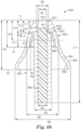
- FIGS. 6a through 6c show an exemplary push-to-fit earplug 600 including a stem 610 and sound attenuating body 620 and having first and second ends 601 and 602.
- Sound attenuating body 620 includes a leading end 621, a base end 622, a tip region 623 and a flange 624. Tip region 623 is located rearwardly of leading end 621 and flange 624 is located between tip region 623 and base end 622.
- sound attenuating body 620 includes an array of cavities 660 positioned within tip region 623 and spaced around the longitudinal axis 10. Cavities 660 provide a collapsible volume that at least a portion of sound attenuating body 620 may collapse into as earplug 100 is advanced into an ear canal of a user.
- Exemplary earplug 600 includes a tip cavity 670 that extends from first end 601 of earplug 600 towards a bottom 671 located nearer second end 602 of earplug 600.
- Tip cavity 670 includes an opening at first end 601 of earplug 600.
- Tip cavity 670 may, in one or more exemplary embodiments, provide a volume into which the surrounding material of sound attenuating body 620, and particularly tip region 621, can collapse as earplug 600 is advanced into an earcanal and/or is resident therein.
- U.S. Application Ser. No. 13/768,214 Earplug with Tip Cavity and Methods of Manufacturing the Same address earplugs having a tip cavity.
- bottom 671 of tip cavity 670 may be spaced from a first end 661 of cavities 660.
- bottom 671 of tip cavity 670 may be spaced a distance (dmin) from a portion of cavities 660, such as first end 661 of cavities 660.
- a minimum distance (dmin) between tip cavity 670 and one or more cavities 660 is between at least 0.3 mm and 3.0 mm, 1 mm and 2.5 mm, or of about 1.5 mm.
- a minimum distance (dmin) within such ranges results in a sufficient stiffness such that a leading end 621 of earplug 600 may be inserted in a user's ear, and improves strength and durability to withstand repeated uses.
- earplug 600 further includes various geometric features 650 of an interior flange surface 626 such that a distance between exterior and interior flange surface 625, 626 varies and flange 624 exhibits different thickness around a perimeter of the flange at a plane intersecting the flange transverse to the longitudinal axis.
- flange 624 may be characterized by a minimum flange thickness (Fmin) and a maximum flange thickness (Fmax) between exterior flange surface 625 and interior flange surface 626.
- flange 624 includes a plurality of geometric features in the form of splines 650 spaced about flange 624 and extending from base end 622 of flange 624 at least partially towards bottom 631 of flange cavity 630.
- Splines 650 exhibit a width (w) between two adjacent locations of a minimum flange thickness (Fmin).
- Geometric features, such as protrusions, recess, or splines 650, affect collapse and/or compression of flange 624 such that undesirable creasing or buckling of flange 624 is minimized.
- An earplug having such geometric flange features facilitates an earplug that is comfortable to wear and minimizes undue noise leakage into an ear canal by limiting creasing or buckling of the flange.
- U.S. Application Ser. No. 14/282,252 Push-To-Fit Earplug Having Geometric Flange Features, addresses earplugs having a plurality of inwardly projecting geometric features.
- Equilibrium force is a rebound force exerted by an earplug when compressed and represents a force exerted by an earplug when positioned in a user's ear canal. Equilibrium force may provide an indication of a relative level of comfort of an earplug.
- Equilibrium force was obtained by placing an earplug conditioned in an environmental room set to 22.8 °C (73 °F) and 50 percent relative humidity for 48 hours between parallel feet having matching straight edges of 20.32 mm (0.8 inches) of a Chatillon DGGS Force Gauge (0.1 gm - 250 gm) mounted on an LTS stand.
- the parallel feet were adjusted using a 9.525 mm (0.375 inch) calibration pin placed between the feet such that spacing between the feet was 9.525 mm (0.375 inches) and a force reading between 20 to 70 grams was obtained.
- the force gauge was positioned in a temperature chamber capable of controlling to 35.6 °C ⁇ 0.6 °C (96°F ⁇ 1 °F).
- a leading end of an earplug is adhered in a 9.5 mm diameter and 25 mm deep recess of a fixture using LOCTITE 403 cyanoacrylate adhesive.
- the fixture was mounted onto a Model 5967 tensile machine available from Instron of Norwood, MA, and the vertically oriented stem portion was clamped in pneumatic jaws of the tensile machine.
- the tensile machine was programmed to pull the fixture and pneumatic jaws until a force of 1.134 kg (2.5 lbs) was achieved and then return to a home position. The home position was maintained for approximately 5 seconds and the tensile machine again pulled to a force of 1.134 kg (2.5 lbs). The process was repeated for 200 cycles or until failure.
- the sample of Examples 1, 2 and Comparative Example A included a core made from PPC1TF2 Pantone 307C (serial # 02271318112) from Washington Penn Plastic Co., Inc. of Frankfort, Kentucky and a sound attenuating portion and stem outer layer made from Kraton SEBS resins with a hardness of 32 Shore A, from Kraton Polymers LLC, of Houston, Texas, and included expanded spheres and a chemical foaming agent.
- the core was coated with the material of the sound attenuating portion and stem outer layer and subsequently placed in a mold and heated to form a sound attenuating portion.
- the earplug of Example 1 included an array of cavities including 8 cavities having trapezoidal cross-sectional shapes uniformly spaced around the longitudinal axis with a shape and configuration shown in Figures 6b and 6c .
- the earplug of Example 2 had a shape and configuration shown in Figures 6b and 7 and included an array of cavities including 6 cavities having generally rectangular cross-sectional shapes uniformly spaced around the longitudinal axis.
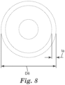
- the earplug of Comparative Example A had a shape and configuration shown in Figures 6b and 8 but did not include an array of cavities.
- Ac cavity area
Landscapes
- Health & Medical Sciences (AREA)
- Life Sciences & Earth Sciences (AREA)
- Biomedical Technology (AREA)
- Heart & Thoracic Surgery (AREA)
- Biophysics (AREA)
- Otolaryngology (AREA)
- Psychology (AREA)
- Engineering & Computer Science (AREA)
- Physics & Mathematics (AREA)
- Acoustics & Sound (AREA)
- Vascular Medicine (AREA)
- Animal Behavior & Ethology (AREA)
- General Health & Medical Sciences (AREA)
- Public Health (AREA)
- Veterinary Medicine (AREA)
- Soundproofing, Sound Blocking, And Sound Damping (AREA)
- Headphones And Earphones (AREA)
- Helmets And Other Head Coverings (AREA)
Applications Claiming Priority (2)
| Application Number | Priority Date | Filing Date | Title |
|---|---|---|---|
| US14/282,266 US10660797B2 (en) | 2014-05-20 | 2014-05-20 | Push-to-fit earplug having an array of cavities |
| PCT/US2015/030066 WO2015179151A1 (en) | 2014-05-20 | 2015-05-11 | Push-to-fit earplug having an array of cavities |
Publications (2)
| Publication Number | Publication Date |
|---|---|
| EP3145461A1 EP3145461A1 (en) | 2017-03-29 |
| EP3145461B1 true EP3145461B1 (en) | 2024-09-11 |
Family
ID=53268886
Family Applications (1)
| Application Number | Title | Priority Date | Filing Date |
|---|---|---|---|
| EP15725161.2A Active EP3145461B1 (en) | 2014-05-20 | 2015-05-11 | Push-to-fit earplug having an array of cavities |
Country Status (9)
| Country | Link |
|---|---|
| US (1) | US10660797B2 (enExample) |
| EP (1) | EP3145461B1 (enExample) |
| JP (2) | JP6576366B2 (enExample) |
| KR (1) | KR102390353B1 (enExample) |
| CN (1) | CN107072819B (enExample) |
| AU (1) | AU2015264620B2 (enExample) |
| BR (1) | BR112016027201B1 (enExample) |
| RU (1) | RU2666259C2 (enExample) |
| WO (1) | WO2015179151A1 (enExample) |
Families Citing this family (11)
| Publication number | Priority date | Publication date | Assignee | Title |
|---|---|---|---|---|
| US20150335489A1 (en) * | 2014-05-20 | 2015-11-26 | 3M Innovative Properties Company | Push-To-Fit Earplug Having Geometric Flange Features |
| AU2018326831B2 (en) * | 2017-09-01 | 2020-07-02 | 3M Innovative Properties Company | Earplug assembly and method for forming the same |
| WO2019043627A2 (en) * | 2017-09-01 | 2019-03-07 | 3M Innovative Properties Company | PUSH-FITTING EAR PLUG WITH HIGH POINT CAVITY |
| USD895901S1 (en) | 2017-09-01 | 2020-09-08 | 3M Innovative Properties Company | Hearing protector |
| CN107684488B (zh) * | 2017-09-30 | 2023-08-25 | 江阴思安塑胶防护科技有限公司 | 可选择式消音器及包括其的降噪耳塞 |
| CN107517422B (zh) * | 2017-09-30 | 2024-04-02 | 江阴思安塑胶防护科技有限公司 | 消音器及包括其的降噪耳塞 |
| EP4034361A1 (en) | 2019-09-27 | 2022-08-03 | 3M Innovative Properties Company | Push-in earplug and method of making the same using a mandrel |
| USD959670S1 (en) * | 2019-12-23 | 2022-08-02 | JMJ Holdings, LLC | Earpiece-foam sizing tool |
| USD952831S1 (en) * | 2021-04-22 | 2022-05-24 | JMJ Holdings, LLC | Earpiece apparatus |
| CN117883238B (zh) * | 2024-03-04 | 2024-12-06 | 广州市行动者科技有限责任公司 | 一种导音管降噪耳塞 |
| USD1039219S1 (en) * | 2024-04-01 | 2024-08-13 | Shenzhen Xiaoyi Technology Innovation Co., Ltd | Earplug |
Family Cites Families (55)
| Publication number | Priority date | Publication date | Assignee | Title |
|---|---|---|---|---|
| GB1050275A (enExample) | 1963-03-05 | |||
| JPS4431107Y1 (enExample) * | 1967-06-05 | 1969-12-22 | ||
| US3638370A (en) | 1970-06-24 | 1972-02-01 | Evon Ind Inc | Fastening structure for securing support brackets to a wall |
| IE47808B1 (en) | 1979-02-01 | 1984-06-27 | Trinity College Dublin | Nmr test method for measuring the homogeneity of dispersions of carbon black in rubber compositions |
| SU822821A1 (ru) | 1979-03-21 | 1981-04-23 | Рижский Краснознаменный Институтгражданской Авиации Им.Ленинскогокомсомола | Ушной вкладыш |
| GB2045159B (en) | 1979-03-28 | 1983-05-11 | Ercol Furniture Ltd | Method of bending wood |
| US4314553A (en) | 1979-08-08 | 1982-02-09 | Bilsom Ab | Earplug and earplug set |
| US4452021A (en) | 1982-02-05 | 1984-06-05 | Construction Concepts, Inc. | Natural wood suspended wood ceiling or wall system employing clip means |
| US4665671A (en) | 1986-03-28 | 1987-05-19 | American Floor Covering Company | Method for assembling an awning |
| USD307635S (en) | 1987-11-05 | 1990-05-01 | Cabot Corporation | Earplug or similar article |
| USD307636S (en) | 1987-11-05 | 1990-05-01 | Cabot Corporation | Earplug or similar article |
| USD307325S (en) | 1987-11-05 | 1990-04-17 | Cabot Corporation | Earplug or similar article |
| USD330761S (en) | 1990-09-21 | 1992-11-03 | Cabot Safety Corporation | Earplug |
| JPH05164199A (ja) | 1991-12-11 | 1993-06-29 | Hino Motors Ltd | 差動制限装置 |
| US5575126A (en) | 1993-12-28 | 1996-11-19 | Mm Systems Corp. | Flat expansion joint gasket |
| USD371193S (en) | 1994-05-16 | 1996-06-25 | Cabot Safety Intermediate Corporation | Hearing protective earplug |
| DE19534455C1 (de) * | 1995-09-16 | 1996-12-12 | Fresenius Ag | PVC-freier-Mehrschichtschlauch für medizinische Zwecke, Verfahren zu dessen Herstellung und Verwendung |
| USD402752S (en) | 1996-08-15 | 1998-12-15 | Cabot Safety Intermediate Corporation | Hearing protective device |
| US5799658A (en) | 1996-08-15 | 1998-09-01 | Cabot Safety Intermediate Corporation | Hearing protective device comprising a foam and a porous component and method of manufacture thereof |
| US5816625A (en) | 1997-08-14 | 1998-10-06 | Clarke; Robert H. | Quick release coupling with spacer ring to align spline rod |
| US6460302B1 (en) | 1999-01-25 | 2002-10-08 | Microstone Building Systems, L.L.C. | Framework-free building system and method of construction |
| CN2439507Y (zh) | 2000-07-09 | 2001-07-18 | 董正林 | 机械密码开关 |
| WO2003053295A1 (en) * | 2000-10-13 | 2003-07-03 | Cabot Safety Intermediate Corporation | Improved flanged earplug |
| USD466995S1 (en) | 2001-11-28 | 2002-12-10 | Cabot Safety Intermediate Corporation | Earplug |
| USD651302S1 (en) | 2002-01-18 | 2011-12-27 | 3M Innovative Properties Company | Earplug |
| WO2003063744A2 (en) | 2002-01-25 | 2003-08-07 | Cabot Safety Intermediate Corporation | Hearing protection device |
| USD471625S1 (en) | 2002-03-14 | 2003-03-11 | Cabot Safety Intermediate Co. | Earplug |
| USD481118S1 (en) | 2002-04-11 | 2003-10-21 | Cabot Safety Intermediate Corporation | Earplug |
| US6681833B2 (en) | 2002-04-23 | 2004-01-27 | Saint-Gobain Bayform America, Inc. | Screen frame having corners under compression |
| USD478658S1 (en) | 2002-09-06 | 2003-08-19 | Cabot Safety Intermediate Corporation | Earplug |
| US6820717B2 (en) * | 2003-01-16 | 2004-11-23 | Howard Leight Industries, Llc | Pressure regulating earplug |
| USD524937S1 (en) | 2004-04-23 | 2006-07-11 | Cabot Safety Intermediate Corporation | Hearing protection device |
| US7464786B2 (en) | 2004-06-11 | 2008-12-16 | Cabot Safety Intermediate Corporation | High sound attenuating hearing protection device |
| USD536089S1 (en) | 2004-10-21 | 2007-01-30 | Moldex-Metric, Inc. | Earplug |
| USD524938S1 (en) | 2005-01-05 | 2006-07-11 | Neesim Health, Llc | Ear piece |
| AU2006206471B9 (en) * | 2005-01-21 | 2011-08-18 | 3M Innovative Properties Company | Hearing protection device with damped material |
| DE202005009132U1 (de) | 2005-06-10 | 2005-08-25 | Uvex Arbeitsschutz Gmbh | Gehörschutzstöpsel |
| JP4783092B2 (ja) | 2005-08-30 | 2011-09-28 | 龍江精工株式会社 | 疑似コアおよびこれを用いる射出成形金型 |
| JP4698379B2 (ja) | 2005-10-17 | 2011-06-08 | ダイハツ工業株式会社 | トルクコンバータ |
| JP4259521B2 (ja) | 2005-12-28 | 2009-04-30 | トヨタ自動車株式会社 | 車両用自動変速機 |
| US20080035281A1 (en) | 2006-08-09 | 2008-02-14 | Kirby David A | Hembar for a shade fabric and assembly method |
| US7984716B2 (en) * | 2007-06-22 | 2011-07-26 | Kimberly-Clark Worldwide Inc. | Self-conforming sound attenuation earplug |
| DE102007042740A1 (de) | 2007-09-07 | 2009-03-12 | Uvex Arbeitsschutz Gmbh | Gehörschutzstöpsel |
| KR20090113923A (ko) | 2008-04-29 | 2009-11-03 | 현해구 | 트랙터용 작업기 자동연결장치 |
| US8113207B2 (en) | 2008-08-22 | 2012-02-14 | Kimberly-Clark Worldwide, Inc. | Self-conforming sound attenuation earplug |
| JP2010059630A (ja) | 2008-09-02 | 2010-03-18 | Masayasu Mifuji | 打ち込み型枠と仮設材を使用しない連結方法 |
| USD606648S1 (en) | 2008-09-22 | 2009-12-22 | Mckeon Products, Inc. | Earplug |
| US8061472B2 (en) * | 2009-06-03 | 2011-11-22 | Sperian Hearing Protection, Llc | Non-roll foam eartip |
| USD636484S1 (en) | 2009-10-22 | 2011-04-19 | Sperian Hearing Protection, Llc | Earplug |
| CN201851555U (zh) | 2010-11-08 | 2011-06-01 | 杭州登峰离合器有限公司 | 一种制动s花键凸插式凸轮轴 |
| KR101191989B1 (ko) | 2012-01-20 | 2012-10-18 | (주)알파정밀 | 이어 팁 및 이를 구비하는 이어폰 |
| US8679607B2 (en) | 2012-07-12 | 2014-03-25 | 3M Innovative Properties Company | Foamable article |
| US9737439B2 (en) * | 2012-07-12 | 2017-08-22 | 3M Innovative Properties Company | Push-in earplug |
| US8968613B2 (en) * | 2012-07-12 | 2015-03-03 | 3M Innovative Properties Company | Method of making an earplug |
| US20150335489A1 (en) | 2014-05-20 | 2015-11-26 | 3M Innovative Properties Company | Push-To-Fit Earplug Having Geometric Flange Features |
-
2014
- 2014-05-20 US US14/282,266 patent/US10660797B2/en active Active
-
2015
- 2015-05-11 BR BR112016027201-3A patent/BR112016027201B1/pt active IP Right Grant
- 2015-05-11 CN CN201580027418.4A patent/CN107072819B/zh active Active
- 2015-05-11 AU AU2015264620A patent/AU2015264620B2/en active Active
- 2015-05-11 EP EP15725161.2A patent/EP3145461B1/en active Active
- 2015-05-11 RU RU2016147227A patent/RU2666259C2/ru active
- 2015-05-11 KR KR1020167035492A patent/KR102390353B1/ko active Active
- 2015-05-11 WO PCT/US2015/030066 patent/WO2015179151A1/en not_active Ceased
- 2015-05-11 JP JP2016568512A patent/JP6576366B2/ja active Active
-
2019
- 2019-07-12 JP JP2019129717A patent/JP6807990B2/ja active Active
Also Published As
| Publication number | Publication date |
|---|---|
| RU2016147227A (ru) | 2018-06-20 |
| AU2015264620A1 (en) | 2016-12-08 |
| KR102390353B1 (ko) | 2022-04-25 |
| JP2019195662A (ja) | 2019-11-14 |
| KR20170009932A (ko) | 2017-01-25 |
| AU2015264620B2 (en) | 2018-03-22 |
| WO2015179151A1 (en) | 2015-11-26 |
| BR112016027201B1 (pt) | 2022-08-02 |
| JP6807990B2 (ja) | 2021-01-06 |
| RU2666259C2 (ru) | 2018-09-06 |
| CN107072819B (zh) | 2020-09-11 |
| US20150335490A1 (en) | 2015-11-26 |
| BR112016027201A2 (enExample) | 2017-08-15 |
| JP6576366B2 (ja) | 2019-09-18 |
| CN107072819A (zh) | 2017-08-18 |
| EP3145461A1 (en) | 2017-03-29 |
| RU2016147227A3 (enExample) | 2018-06-20 |
| JP2017516419A (ja) | 2017-06-15 |
| US10660797B2 (en) | 2020-05-26 |
Similar Documents
| Publication | Publication Date | Title |
|---|---|---|
| EP3145461B1 (en) | Push-to-fit earplug having an array of cavities | |
| EP3145460B1 (en) | Push-to-fit earplug having geometric flange features | |
| EP2068795B1 (en) | Self-conforming sound attenuation earplug | |
| KR101569546B1 (ko) | 이도관 내에 위치시키기 위한 자가 맞춤 장치 | |
| AU2017200603B2 (en) | Earplug with tip cavity and methods of manufacturing the same | |
| MX2011001967A (es) | Tapon auditivo de atenuacion del sonido de auto conformacion. | |
| AU2018200558B2 (en) | Molded foam push-to-fit earplug, method and devices | |
| CN111031975A (zh) | 带有末端腔的推入贴合型耳塞 |
Legal Events
| Date | Code | Title | Description |
|---|---|---|---|
| STAA | Information on the status of an ep patent application or granted ep patent |
Free format text: STATUS: THE INTERNATIONAL PUBLICATION HAS BEEN MADE |
|
| PUAI | Public reference made under article 153(3) epc to a published international application that has entered the european phase |
Free format text: ORIGINAL CODE: 0009012 |
|
| STAA | Information on the status of an ep patent application or granted ep patent |
Free format text: STATUS: REQUEST FOR EXAMINATION WAS MADE |
|
| 17P | Request for examination filed |
Effective date: 20161123 |
|
| AK | Designated contracting states |
Kind code of ref document: A1 Designated state(s): AL AT BE BG CH CY CZ DE DK EE ES FI FR GB GR HR HU IE IS IT LI LT LU LV MC MK MT NL NO PL PT RO RS SE SI SK SM TR |
|
| AX | Request for extension of the european patent |
Extension state: BA ME |
|
| DAV | Request for validation of the european patent (deleted) | ||
| DAX | Request for extension of the european patent (deleted) | ||
| STAA | Information on the status of an ep patent application or granted ep patent |
Free format text: STATUS: EXAMINATION IS IN PROGRESS |
|
| 17Q | First examination report despatched |
Effective date: 20180216 |
|
| GRAP | Despatch of communication of intention to grant a patent |
Free format text: ORIGINAL CODE: EPIDOSNIGR1 |
|
| STAA | Information on the status of an ep patent application or granted ep patent |
Free format text: STATUS: GRANT OF PATENT IS INTENDED |
|
| INTG | Intention to grant announced |
Effective date: 20240516 |
|
| GRAS | Grant fee paid |
Free format text: ORIGINAL CODE: EPIDOSNIGR3 |
|
| P01 | Opt-out of the competence of the unified patent court (upc) registered |
Free format text: CASE NUMBER: APP_39560/2024 Effective date: 20240703 |
|
| GRAA | (expected) grant |
Free format text: ORIGINAL CODE: 0009210 |
|
| STAA | Information on the status of an ep patent application or granted ep patent |
Free format text: STATUS: THE PATENT HAS BEEN GRANTED |
|
| AK | Designated contracting states |
Kind code of ref document: B1 Designated state(s): AL AT BE BG CH CY CZ DE DK EE ES FI FR GB GR HR HU IE IS IT LI LT LU LV MC MK MT NL NO PL PT RO RS SE SI SK SM TR |
|
| REG | Reference to a national code |
Ref country code: GB Ref legal event code: FG4D |
|
| REG | Reference to a national code |
Ref country code: CH Ref legal event code: EP |
|
| REG | Reference to a national code |
Ref country code: DE Ref legal event code: R096 Ref document number: 602015089856 Country of ref document: DE |
|
| REG | Reference to a national code |
Ref country code: IE Ref legal event code: FG4D |
|
| REG | Reference to a national code |
Ref country code: LT Ref legal event code: MG9D |
|
| PG25 | Lapsed in a contracting state [announced via postgrant information from national office to epo] |
Ref country code: NO Free format text: LAPSE BECAUSE OF FAILURE TO SUBMIT A TRANSLATION OF THE DESCRIPTION OR TO PAY THE FEE WITHIN THE PRESCRIBED TIME-LIMIT Effective date: 20241211 |
|
| REG | Reference to a national code |
Ref country code: NL Ref legal event code: MP Effective date: 20240911 |
|
| PG25 | Lapsed in a contracting state [announced via postgrant information from national office to epo] |
Ref country code: GR Free format text: LAPSE BECAUSE OF FAILURE TO SUBMIT A TRANSLATION OF THE DESCRIPTION OR TO PAY THE FEE WITHIN THE PRESCRIBED TIME-LIMIT Effective date: 20241212 Ref country code: FI Free format text: LAPSE BECAUSE OF FAILURE TO SUBMIT A TRANSLATION OF THE DESCRIPTION OR TO PAY THE FEE WITHIN THE PRESCRIBED TIME-LIMIT Effective date: 20240911 |
|
| PG25 | Lapsed in a contracting state [announced via postgrant information from national office to epo] |
Ref country code: BG Free format text: LAPSE BECAUSE OF FAILURE TO SUBMIT A TRANSLATION OF THE DESCRIPTION OR TO PAY THE FEE WITHIN THE PRESCRIBED TIME-LIMIT Effective date: 20240911 |
|
| PG25 | Lapsed in a contracting state [announced via postgrant information from national office to epo] |
Ref country code: LV Free format text: LAPSE BECAUSE OF FAILURE TO SUBMIT A TRANSLATION OF THE DESCRIPTION OR TO PAY THE FEE WITHIN THE PRESCRIBED TIME-LIMIT Effective date: 20240911 |
|
| PG25 | Lapsed in a contracting state [announced via postgrant information from national office to epo] |
Ref country code: HR Free format text: LAPSE BECAUSE OF FAILURE TO SUBMIT A TRANSLATION OF THE DESCRIPTION OR TO PAY THE FEE WITHIN THE PRESCRIBED TIME-LIMIT Effective date: 20240911 |
|
| PG25 | Lapsed in a contracting state [announced via postgrant information from national office to epo] |
Ref country code: ES Free format text: LAPSE BECAUSE OF FAILURE TO SUBMIT A TRANSLATION OF THE DESCRIPTION OR TO PAY THE FEE WITHIN THE PRESCRIBED TIME-LIMIT Effective date: 20240911 Ref country code: RS Free format text: LAPSE BECAUSE OF FAILURE TO SUBMIT A TRANSLATION OF THE DESCRIPTION OR TO PAY THE FEE WITHIN THE PRESCRIBED TIME-LIMIT Effective date: 20241211 |
|
| PG25 | Lapsed in a contracting state [announced via postgrant information from national office to epo] |
Ref country code: RS Free format text: LAPSE BECAUSE OF FAILURE TO SUBMIT A TRANSLATION OF THE DESCRIPTION OR TO PAY THE FEE WITHIN THE PRESCRIBED TIME-LIMIT Effective date: 20241211 Ref country code: NO Free format text: LAPSE BECAUSE OF FAILURE TO SUBMIT A TRANSLATION OF THE DESCRIPTION OR TO PAY THE FEE WITHIN THE PRESCRIBED TIME-LIMIT Effective date: 20241211 Ref country code: LV Free format text: LAPSE BECAUSE OF FAILURE TO SUBMIT A TRANSLATION OF THE DESCRIPTION OR TO PAY THE FEE WITHIN THE PRESCRIBED TIME-LIMIT Effective date: 20240911 Ref country code: HR Free format text: LAPSE BECAUSE OF FAILURE TO SUBMIT A TRANSLATION OF THE DESCRIPTION OR TO PAY THE FEE WITHIN THE PRESCRIBED TIME-LIMIT Effective date: 20240911 Ref country code: GR Free format text: LAPSE BECAUSE OF FAILURE TO SUBMIT A TRANSLATION OF THE DESCRIPTION OR TO PAY THE FEE WITHIN THE PRESCRIBED TIME-LIMIT Effective date: 20241212 Ref country code: FI Free format text: LAPSE BECAUSE OF FAILURE TO SUBMIT A TRANSLATION OF THE DESCRIPTION OR TO PAY THE FEE WITHIN THE PRESCRIBED TIME-LIMIT Effective date: 20240911 Ref country code: ES Free format text: LAPSE BECAUSE OF FAILURE TO SUBMIT A TRANSLATION OF THE DESCRIPTION OR TO PAY THE FEE WITHIN THE PRESCRIBED TIME-LIMIT Effective date: 20240911 Ref country code: BG Free format text: LAPSE BECAUSE OF FAILURE TO SUBMIT A TRANSLATION OF THE DESCRIPTION OR TO PAY THE FEE WITHIN THE PRESCRIBED TIME-LIMIT Effective date: 20240911 |
|
| REG | Reference to a national code |
Ref country code: AT Ref legal event code: MK05 Ref document number: 1722044 Country of ref document: AT Kind code of ref document: T Effective date: 20240911 |
|
| PG25 | Lapsed in a contracting state [announced via postgrant information from national office to epo] |
Ref country code: NL Free format text: LAPSE BECAUSE OF FAILURE TO SUBMIT A TRANSLATION OF THE DESCRIPTION OR TO PAY THE FEE WITHIN THE PRESCRIBED TIME-LIMIT Effective date: 20240911 |
|
| PG25 | Lapsed in a contracting state [announced via postgrant information from national office to epo] |
Ref country code: IS Free format text: LAPSE BECAUSE OF FAILURE TO SUBMIT A TRANSLATION OF THE DESCRIPTION OR TO PAY THE FEE WITHIN THE PRESCRIBED TIME-LIMIT Effective date: 20250111 Ref country code: PT Free format text: LAPSE BECAUSE OF FAILURE TO SUBMIT A TRANSLATION OF THE DESCRIPTION OR TO PAY THE FEE WITHIN THE PRESCRIBED TIME-LIMIT Effective date: 20250113 |
|
| PG25 | Lapsed in a contracting state [announced via postgrant information from national office to epo] |
Ref country code: RO Free format text: LAPSE BECAUSE OF FAILURE TO SUBMIT A TRANSLATION OF THE DESCRIPTION OR TO PAY THE FEE WITHIN THE PRESCRIBED TIME-LIMIT Effective date: 20240911 Ref country code: SM Free format text: LAPSE BECAUSE OF FAILURE TO SUBMIT A TRANSLATION OF THE DESCRIPTION OR TO PAY THE FEE WITHIN THE PRESCRIBED TIME-LIMIT Effective date: 20240911 |
|
| PG25 | Lapsed in a contracting state [announced via postgrant information from national office to epo] |
Ref country code: EE Free format text: LAPSE BECAUSE OF FAILURE TO SUBMIT A TRANSLATION OF THE DESCRIPTION OR TO PAY THE FEE WITHIN THE PRESCRIBED TIME-LIMIT Effective date: 20240911 Ref country code: AT Free format text: LAPSE BECAUSE OF FAILURE TO SUBMIT A TRANSLATION OF THE DESCRIPTION OR TO PAY THE FEE WITHIN THE PRESCRIBED TIME-LIMIT Effective date: 20240911 |
|
| PG25 | Lapsed in a contracting state [announced via postgrant information from national office to epo] |
Ref country code: CZ Free format text: LAPSE BECAUSE OF FAILURE TO SUBMIT A TRANSLATION OF THE DESCRIPTION OR TO PAY THE FEE WITHIN THE PRESCRIBED TIME-LIMIT Effective date: 20240911 Ref country code: PL Free format text: LAPSE BECAUSE OF FAILURE TO SUBMIT A TRANSLATION OF THE DESCRIPTION OR TO PAY THE FEE WITHIN THE PRESCRIBED TIME-LIMIT Effective date: 20240911 |
|
| PG25 | Lapsed in a contracting state [announced via postgrant information from national office to epo] |
Ref country code: SK Free format text: LAPSE BECAUSE OF FAILURE TO SUBMIT A TRANSLATION OF THE DESCRIPTION OR TO PAY THE FEE WITHIN THE PRESCRIBED TIME-LIMIT Effective date: 20240911 Ref country code: IT Free format text: LAPSE BECAUSE OF FAILURE TO SUBMIT A TRANSLATION OF THE DESCRIPTION OR TO PAY THE FEE WITHIN THE PRESCRIBED TIME-LIMIT Effective date: 20240911 |
|
| REG | Reference to a national code |
Ref country code: DE Ref legal event code: R097 Ref document number: 602015089856 Country of ref document: DE |
|
| PGFP | Annual fee paid to national office [announced via postgrant information from national office to epo] |
Ref country code: DE Payment date: 20250423 Year of fee payment: 11 |
|
| PG25 | Lapsed in a contracting state [announced via postgrant information from national office to epo] |
Ref country code: DK Free format text: LAPSE BECAUSE OF FAILURE TO SUBMIT A TRANSLATION OF THE DESCRIPTION OR TO PAY THE FEE WITHIN THE PRESCRIBED TIME-LIMIT Effective date: 20240911 |
|
| PLBE | No opposition filed within time limit |
Free format text: ORIGINAL CODE: 0009261 |
|
| STAA | Information on the status of an ep patent application or granted ep patent |
Free format text: STATUS: NO OPPOSITION FILED WITHIN TIME LIMIT |
|
| 26N | No opposition filed |
Effective date: 20250612 |
|
| PG25 | Lapsed in a contracting state [announced via postgrant information from national office to epo] |
Ref country code: SE Free format text: LAPSE BECAUSE OF FAILURE TO SUBMIT A TRANSLATION OF THE DESCRIPTION OR TO PAY THE FEE WITHIN THE PRESCRIBED TIME-LIMIT Effective date: 20240911 |
|
| REG | Reference to a national code |
Ref country code: CH Ref legal event code: H13 Free format text: ST27 STATUS EVENT CODE: U-0-0-H10-H13 (AS PROVIDED BY THE NATIONAL OFFICE) Effective date: 20251223 |
|
| PG25 | Lapsed in a contracting state [announced via postgrant information from national office to epo] |
Ref country code: LU Free format text: LAPSE BECAUSE OF NON-PAYMENT OF DUE FEES Effective date: 20250511 |
|
| PG25 | Lapsed in a contracting state [announced via postgrant information from national office to epo] |
Ref country code: CH Free format text: LAPSE BECAUSE OF NON-PAYMENT OF DUE FEES Effective date: 20250531 |
|
| GBPC | Gb: european patent ceased through non-payment of renewal fee |
Effective date: 20250511 |
|
| REG | Reference to a national code |
Ref country code: BE Ref legal event code: MM Effective date: 20250531 |
|
| PG25 | Lapsed in a contracting state [announced via postgrant information from national office to epo] |
Ref country code: MC Free format text: LAPSE BECAUSE OF FAILURE TO SUBMIT A TRANSLATION OF THE DESCRIPTION OR TO PAY THE FEE WITHIN THE PRESCRIBED TIME-LIMIT Effective date: 20240911 |
|
| PG25 | Lapsed in a contracting state [announced via postgrant information from national office to epo] |
Ref country code: GB Free format text: LAPSE BECAUSE OF NON-PAYMENT OF DUE FEES Effective date: 20250511 |
|
| PG25 | Lapsed in a contracting state [announced via postgrant information from national office to epo] |
Ref country code: IE Free format text: LAPSE BECAUSE OF NON-PAYMENT OF DUE FEES Effective date: 20250511 |
|
| PG25 | Lapsed in a contracting state [announced via postgrant information from national office to epo] |
Ref country code: BE Free format text: LAPSE BECAUSE OF NON-PAYMENT OF DUE FEES Effective date: 20250531 |
|
| PG25 | Lapsed in a contracting state [announced via postgrant information from national office to epo] |
Ref country code: FR Free format text: LAPSE BECAUSE OF NON-PAYMENT OF DUE FEES Effective date: 20250531 |