EP3145375B1 - Air heating device - Google Patents
Air heating device Download PDFInfo
- Publication number
- EP3145375B1 EP3145375B1 EP15742401.1A EP15742401A EP3145375B1 EP 3145375 B1 EP3145375 B1 EP 3145375B1 EP 15742401 A EP15742401 A EP 15742401A EP 3145375 B1 EP3145375 B1 EP 3145375B1
- Authority
- EP
- European Patent Office
- Prior art keywords
- air
- heating device
- air heating
- lower side
- product holder
- Prior art date
- Legal status (The legal status is an assumption and is not a legal conclusion. Google has not performed a legal analysis and makes no representation as to the accuracy of the status listed.)
- Active
Links
- 238000010438 heat treatment Methods 0.000 title claims description 42
- 238000002360 preparation method Methods 0.000 claims description 4
- 239000000126 substance Substances 0.000 claims description 3
- 238000004806 packaging method and process Methods 0.000 description 4
- 235000001674 Agaricus brunnescens Nutrition 0.000 description 1
- 229920002472 Starch Polymers 0.000 description 1
- 239000000470 constituent Substances 0.000 description 1
- 238000006073 displacement reaction Methods 0.000 description 1
- 230000002349 favourable effect Effects 0.000 description 1
- 239000000796 flavoring agent Substances 0.000 description 1
- 235000019634 flavors Nutrition 0.000 description 1
- 239000010794 food waste Substances 0.000 description 1
- 238000005259 measurement Methods 0.000 description 1
- 235000019698 starch Nutrition 0.000 description 1
- 239000008107 starch Substances 0.000 description 1
- 230000000007 visual effect Effects 0.000 description 1
- XLYOFNOQVPJJNP-UHFFFAOYSA-N water Substances O XLYOFNOQVPJJNP-UHFFFAOYSA-N 0.000 description 1
Images


Classifications
-
- A—HUMAN NECESSITIES
- A47—FURNITURE; DOMESTIC ARTICLES OR APPLIANCES; COFFEE MILLS; SPICE MILLS; SUCTION CLEANERS IN GENERAL
- A47J—KITCHEN EQUIPMENT; COFFEE MILLS; SPICE MILLS; APPARATUS FOR MAKING BEVERAGES
- A47J37/00—Baking; Roasting; Grilling; Frying
- A47J37/06—Roasters; Grills; Sandwich grills
- A47J37/0623—Small-size cooking ovens, i.e. defining an at least partially closed cooking cavity
- A47J37/0629—Small-size cooking ovens, i.e. defining an at least partially closed cooking cavity with electric heating elements
- A47J37/0641—Small-size cooking ovens, i.e. defining an at least partially closed cooking cavity with electric heating elements with forced air circulation, e.g. air fryers
Definitions
- the present invention relates to an air heating device, in which a product is prepared for consumption by means of hot air.
- the document WO 2012/032449 A1 discloses an air heating device. Therefore, it is an object of the present invention to provide an air heating device which optimally obviates the abovementioned drawbacks, which takes up a limited surface area and which occupies a limited volume, and which is also better accepted by the general public.
- the air heating device comprises the features mentioned in claim 1.
- An advantage of the device according to the invention resides in that the various constituents of the device enable a compact structure which is tailored for universal use, in particular if the heating elements are provided at or against the outside surface of the possibly cylindrical product holder.
- the product holder comprises an air permeable structure only on the upper and lower side, the product holder is integrated in a space-saving manner in the air circulation system during operation of the device.
- a further embodiment of the device according to the invention is characterized in that the product holder and the air heating device are arranged such that the product holder is removably placeable therein.
- An advantage of this feature resides in that, by virtue thereof, the compact arrangement according to the invention also corresponds, as to the external characteristics thereof and the operations to be performed, to an electric water boiler or coffee maker, which have gained a steady place in today's kitchens.
- a still further embodiment of the device according to the invention is characterized in that the air circulation system comprises at least one fan, which is connected to control elements by means of which the direction of the air circulating past the products can be reversed.
- the product can be heated from above or from below as desired, so that the finished product is heated more uniformly.
- the control elements used for this purpose are either electrical and/or mechanical.
- a subsequent embodiment of the air heating device is characterized in that it comprises a manifold space, on the upper side or the lower side, which manifold space is incorporated in the air circulation system and in which a removable or unremovable aerodynamic element is provided which is shaped such that it influences the air inflow/outflow pattern on the relevant side(s).
- a further embodiment of the relevant device according to the invention is characterized in that the air heating device comprises an air humidity measuring system with one or more sensors, arranged to measure the air humidity on the upper and/or lower side.
- the absolute moisture content and/or the difference in moisture content can be determined after measurement in order to be used as a measure for reporting that the product is ready.
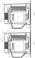
- Figure 1 shows an air heating device 1 for products, which may or may not contain starch, which are to provided in a product holder 2.
- the products which may or may not be partly pre-packaged, are separately placed in the product holder 2 or they are placed in said product holder 2 in their entirely or partly open or perforated packaging.
- the products are packaged in measured weight quantities or measured volume quantities, and the volume and/or the shape of the product holder is adapted to said packaging.
- the device 1 remains compact and does not take up more space than strictly necessary to make the pre-packaged products ready for consumption. In practice a substantial part of the products will have been baked already before they are reheated by the device 1.
- the device 1 therefor comprises an air circulation system 3 which causes air to circulate via the upper side 4-1 and the lower side 4-2 of the product holder 2.
- These sides hereinafter indicated by means of reference numeral 4 for brevity, are provided with an air-permeable structure 5, for example in the form of a basket or grid.
- the upper side may be open, which is considered here as an air permeable structure for simplicity. If only the upper and lower side(s) 4 are air permeable, then there is no need for air to flow along the side face, so that, as shown here, the device 1 remains slim.
- the air can flow from top to bottom or conversely, or it can flow alternately from top to bottom and from bottom to top through the product holder 2 during one heating cycle.
- heating elements 6 are incorporated which heat the air flowing through them that flows from and to the sides above and below the product holder 2.
- the heating capacity and hence the electric power consumption of the heating elements 6 is such that it is adapted to the abovementioned measured packaging.
- the heating elements 6, which are of limited width, are arranged in the air circulation system 3 so as to be at or against, or at least close to the preferably cylindrical outer surface of the product holder 2. This provides the device 1 with an attractive asymmetric appearance as shown in figures 4a and 4b .
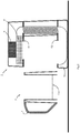
- FIG 2 it is schematically shown that the product holder 2 and the air heating device 1 are arranged such that the product holder 2 is removably placeable therein.
- the product holder 2 which is bounded on the lower side by the grid structure 5, is provided with a grip 7.
- the device 1 will in practice comprise at least one fan 8, which is positioned in the air circulation system 3 and, as shown here, above the product holder 2.
- the fan 8 can cause air to flow through the air circulation system 3 in one direction or another.
- a suitable mechanical control element is an air check valve, which is not shown.
- Figure 2 schematically shows an electric motor inverter, taking up a limited volume, as the control element 9 for the fan 8, which inverter may be combined, if necessary, with a circuit for controlling the amount of air displacement, for example as a function of time and/or quantities to be explained hereinafter.
- Figure 3 shows that the device 1 comprises a removable drawer 10 arranged at some distance below the lower side 4-2 of the product holder 2.
- food residues such as crumbs can collect in the drawer 10 or at least in a part thereof, so that they are not circulated in the air circulation system 3.
- the fan 8 in the air circulation system 3 will be sufficiently powerful to make the circulated hot air flow uniformly through the product in the product holder 2, so that the product heats up uniformly throughout the volume thereof.
- the electric power consumption of the fan 8 is preferably adapted to the abovementioned measured packaging of the product, so that the volume and the noise produced by the air circulation system 3 will be minimal.
- an air flow distributor is superfluous.
- a detachable or non-detachable aerodynamic element may be provided in a manifold space 11 forming part of the air circulation system 3, said aerodynamic element being shaped such that it influences the air inflow/outflow pattern on the relevant side(s) of the product holder 2 or distributes said pattern according to the requirements.
- This aerodynamic element could have the shape of a lying fanning-out mushroom that matches the asymmetric structure of the device 1, enabling it, as shown in fig. 1a , to guide air in a uniform manner to the bottom side 4-2 of the product holder 2.
- the device 1 may comprise a measuring, control and warning system including corresponding measuring sensors S1 and S2 to measure said quantities, such as temperature and/or humidity of the air particularly on the upper side 4-1 and/or lower side 4-2 and to the determine, based on said values, whether the product is ready.
- This system is capable of measuring air temperature and/or humidity and particularly the difference in temperature and/or the difference in relative or absolute humidity between said sides.
- the system is further arranged to determine, based on said values, whether the product is ready and give an audible and/or visual warning.
- the above-mentioned drawer 10, the manifold space 11 and/or the aerodynamic element make it possible to add, to the passing air, if necessary in compartments of said parts, dry or moist substances or moisture, which may or may not be spiced and/or aromatized and which are important for the preparation of the products.
- the use thereof during the heating process adds a desired flavour element to the prepared product. Furthermore, this has a favourable effect on the texture and the moisture content of certain products.
Landscapes
- Engineering & Computer Science (AREA)
- Food Science & Technology (AREA)
- Drying Of Solid Materials (AREA)
- Devices For Warming Or Keeping Food Or Tableware Hot (AREA)
Description
- The present invention relates to an air heating device, in which a product is prepared for consumption by means of hot air.
- Such devices are generally known. In order to be attractive to buyers, an air heating device, in addition to the oven generally already present in a kitchen, must have added value and provide universal use. In addition, the purchase of such a device should not place an additional burden on the environment or take up a lot of space or cause noise pollution in the kitchen. Hitherto, these factors stand in the way of wider acceptance by potential buyers and their propensity to purchase, both in the professional kitchen and in the kitchen at home.
- The document
WO 2012/032449 A1 discloses an air heating device. Therefore, it is an object of the present invention to provide an air heating device which optimally obviates the abovementioned drawbacks, which takes up a limited surface area and which occupies a limited volume, and which is also better accepted by the general public. - To achieve this, the air heating device according to the invention comprises the features mentioned in
claim 1. - An advantage of the device according to the invention resides in that the various constituents of the device enable a compact structure which is tailored for universal use, in particular if the heating elements are provided at or against the outside surface of the possibly cylindrical product holder.
- If the product holder comprises an air permeable structure only on the upper and lower side, the product holder is integrated in a space-saving manner in the air circulation system during operation of the device.
- A further embodiment of the device according to the invention is characterized in that the product holder and the air heating device are arranged such that the product holder is removably placeable therein.
- An advantage of this feature resides in that, by virtue thereof, the compact arrangement according to the invention also corresponds, as to the external characteristics thereof and the operations to be performed, to an electric water boiler or coffee maker, which have gained a steady place in today's kitchens.
- A still further embodiment of the device according to the invention is characterized in that the air circulation system comprises at least one fan, which is connected to control elements by means of which the direction of the air circulating past the products can be reversed.
- This has the advantage that, either manually or periodically, the direction of the air flow through the product holder can be automatically reversed. By virtue thereof, the product can be heated from above or from below as desired, so that the finished product is heated more uniformly. The control elements used for this purpose are either electrical and/or mechanical.
- In order to achieve, at a minimal air resistance and a correspondingly low fan power, an optimum distribution of air or heat over the product surface on the upper or lower side, a subsequent embodiment of the air heating device is characterized in that it comprises a manifold space, on the upper side or the lower side, which manifold space is incorporated in the air circulation system and in which a removable or unremovable aerodynamic element is provided which is shaped such that it influences the air inflow/outflow pattern on the relevant side(s).
- A further embodiment of the relevant device according to the invention is characterized in that the air heating device comprises an air humidity measuring system with one or more sensors, arranged to measure the air humidity on the upper and/or lower side.
- The absolute moisture content and/or the difference in moisture content can be determined after measurement in order to be used as a measure for reporting that the product is ready.
- Further detailed, possible embodiments, which are set forth in the remaining claims, are mentioned together with the associated advantages in the following description.
- The air heating device according to the present invention will now be explained in greater detail with reference to the figures mentioned below, in which corresponding parts are indicated by means of the same reference numerals. In the Figures:
-
Figures 1a and 1b are schematic representations of embodiments of the air heating device according to the invention, in which the air circulates in one of two directions; -
Figure 2 schematically shows the removable product used in the device shown infigures 1a and 1b ; -
Figure 3 schematically shows the removable drawer at the bottom of device shown infigures 1a and 1b ; and -
Figures 4a and 4b show the external shape of the device shown infigures 1a and 1b , and the removed product holder to be used therein, respectively. -
Figure 1 shows anair heating device 1 for products, which may or may not contain starch, which are to provided in aproduct holder 2. The products, which may or may not be partly pre-packaged, are separately placed in theproduct holder 2 or they are placed in saidproduct holder 2 in their entirely or partly open or perforated packaging. Preferably the products are packaged in measured weight quantities or measured volume quantities, and the volume and/or the shape of the product holder is adapted to said packaging. By virtue thereof, thedevice 1 remains compact and does not take up more space than strictly necessary to make the pre-packaged products ready for consumption. In practice a substantial part of the products will have been baked already before they are reheated by thedevice 1. - The
device 1 therefor comprises anair circulation system 3 which causes air to circulate via the upper side 4-1 and the lower side 4-2 of theproduct holder 2. These sides, hereinafter indicated by means of reference numeral 4 for brevity, are provided with an air-permeable structure 5, for example in the form of a basket or grid. As shown here, the upper side may be open, which is considered here as an air permeable structure for simplicity. If only the upper and lower side(s) 4 are air permeable, then there is no need for air to flow along the side face, so that, as shown here, thedevice 1 remains slim. In a manner which will be explained in more detail hereinafter, the air can flow from top to bottom or conversely, or it can flow alternately from top to bottom and from bottom to top through theproduct holder 2 during one heating cycle. - In the
air circulating system 3,heating elements 6 are incorporated which heat the air flowing through them that flows from and to the sides above and below theproduct holder 2. Again preferably, the heating capacity and hence the electric power consumption of theheating elements 6 is such that it is adapted to the abovementioned measured packaging. By virtue thereof, overcapacity, which would lead to a larger volume taken up, is precluded, and in addition the preparation time of the relevant product is known in advance when the heating operation starts, because the preparation temperature is known, so that a user can rely on this and perform other operations in the kitchen in the meantime. - In the embodiment shown in
figures 1a and 1b , theheating elements 6, which are of limited width, are arranged in theair circulation system 3 so as to be at or against, or at least close to the preferably cylindrical outer surface of theproduct holder 2. This provides thedevice 1 with an attractive asymmetric appearance as shown infigures 4a and 4b . - In
figure 2 , it is schematically shown that theproduct holder 2 and theair heating device 1 are arranged such that theproduct holder 2 is removably placeable therein. To enable simple removal and replacement, theproduct holder 2, which is bounded on the lower side by thegrid structure 5, is provided with agrip 7. - In order to be able to rapidly provide a well prepared finished product, the
device 1 will in practice comprise at least onefan 8, which is positioned in theair circulation system 3 and, as shown here, above theproduct holder 2. By means of suitable mechanical or electrical control elements 9, thefan 8 can cause air to flow through theair circulation system 3 in one direction or another. A suitable mechanical control element is an air check valve, which is not shown.Figure 2 schematically shows an electric motor inverter, taking up a limited volume, as the control element 9 for thefan 8, which inverter may be combined, if necessary, with a circuit for controlling the amount of air displacement, for example as a function of time and/or quantities to be explained hereinafter. -
Figure 3 shows that thedevice 1 comprises aremovable drawer 10 arranged at some distance below the lower side 4-2 of theproduct holder 2. In principle, food residues such as crumbs can collect in thedrawer 10 or at least in a part thereof, so that they are not circulated in theair circulation system 3. Thefan 8 in theair circulation system 3 will be sufficiently powerful to make the circulated hot air flow uniformly through the product in theproduct holder 2, so that the product heats up uniformly throughout the volume thereof. Again, the electric power consumption of thefan 8 is preferably adapted to the abovementioned measured packaging of the product, so that the volume and the noise produced by theair circulation system 3 will be minimal. If the dimensions of thefan 8 are sufficient to enable the fan to independently provide a sufficiently uniform air flow through the product in theproduct holder 2, an air flow distributor is superfluous. For example, on the lower side shown, a detachable or non-detachable aerodynamic element, not shown here, may be provided in amanifold space 11 forming part of theair circulation system 3, said aerodynamic element being shaped such that it influences the air inflow/outflow pattern on the relevant side(s) of theproduct holder 2 or distributes said pattern according to the requirements. This aerodynamic element could have the shape of a lying fanning-out mushroom that matches the asymmetric structure of thedevice 1, enabling it, as shown infig. 1a , to guide air in a uniform manner to the bottom side 4-2 of theproduct holder 2. - The
device 1 may comprise a measuring, control and warning system including corresponding measuring sensors S1 and S2 to measure said quantities, such as temperature and/or humidity of the air particularly on the upper side 4-1 and/or lower side 4-2 and to the determine, based on said values, whether the product is ready. This system is capable of measuring air temperature and/or humidity and particularly the difference in temperature and/or the difference in relative or absolute humidity between said sides. The system is further arranged to determine, based on said values, whether the product is ready and give an audible and/or visual warning. - The above-mentioned
drawer 10, themanifold space 11 and/or the aerodynamic element make it possible to add, to the passing air, if necessary in compartments of said parts, dry or moist substances or moisture, which may or may not be spiced and/or aromatized and which are important for the preparation of the products. This could be achieved by placing small interior receptacles, which may or may not be of a disposable type, in said compartments. The use thereof during the heating process adds a desired flavour element to the prepared product. Furthermore, this has a favourable effect on the texture and the moisture content of certain products.
Claims (12)
- An air heating device (1) for products, comprising:- a product holder (2) with at least an upper (4-1) and a lower (4-2) side provided with an air permeable structure (5),- an air circulation system (3) connected to said upper and lower side, and- heating elements (6) incorporated in said air circulation system,wherein:- said air circulation system (3) is arranged to guide the air passed through the product holder (2) from one of the upper and lower side via the heating elements to the other one of the upper and lower side; characterized in that- the air heating device comprises a temperature measuring system with two or more sensors (S1, S2), arranged to measure the air temperature on the upper and lower side, wherein the temperature measuring system is arranged to determine at least the temperature difference between the air passing on the upper side (4-1) and the lower side (4-2), and to use the measured temperature difference to determine whether the product is ready.
- The air heating device according to claim 1, characterized in that the heating elements (6) are provided at or against the outside surface of the possibly cylindrical product holder.
- The air heating device according to claim 1 or 2, characterized in that the product holder (2) comprises an air permeable structure only on the upper and lower side thereof.
- The air heating device according to any of the preceding claims,
characterized in that the product holder (2) and the air heating device (1) are arranged such that the product holder is removably placeable therein. - The air heating device according to any of the preceding claims,
characterized in that the air circulation system (3) comprises at least one fan (8), which is connected to control elements (9) by means of which the direction of the air flow circulating through the products can be reversed. - The air heating device according to claim 5, characterized in that the control elements (9) may be electrically driven, provided with an electric inverter, or mechanically driven, provided with an air check valve.
- The air heating device according to any of the preceding claims,
characterized in that the air heating device (1) comprises, on at least one of the upper side and lower side, a manifold space (11) incorporated in the air circulation system (3), in which manifold space a detachable or non-detachable aerodynamic element is provided which is shaped such that it influences the air inflow/outflow pattern on the relevant side(s). - The air heating device according to any of the preceding claims,
characterized in that the air heating device (1) comprises an air humidity measuring system with one or more sensors, arranged to measure the humidity on the upper and/or lower side. - The air heating device according to claim 8, characterized in that the air humidity measuring system is arranged to determine at least the difference in absolute or relative moisture content of the air passing on the upper side and the lower side, and to use the measured difference in absolute or relative moisture content to determine whether the product is ready.
- The air heating device according to any of the preceding claims,
characterized in that the air heating device comprises a removable drawer (10) arranged at some distance below the lower side of the product holder (2) or below the aerodynamic element. - The air heating device according to claim 10, characterized in that the air heating device (1) is constructed to make the air pass over the drawer (10), if necessary via the aerodynamic element, towards the lower side of the product holder.
- The air heating device according to claim 10 or 11, characterized in that the drawer (10) is built up of one or more compartments suitable for collecting grains, crumbs or residues of the heated products, and/or for providing one or more dry or moist substances or moisture in said compartments, which substances or moisture may or may not be spiced and/or aromatized and which are important for the preparation of the products.
Priority Applications (1)
| Application Number | Priority Date | Filing Date | Title |
|---|---|---|---|
| PL15742401T PL3145375T3 (en) | 2014-07-07 | 2015-07-02 | Air heating device |
Applications Claiming Priority (2)
| Application Number | Priority Date | Filing Date | Title |
|---|---|---|---|
| NL2013137A NL2013137B1 (en) | 2014-07-07 | 2014-07-07 | Air heating device. |
| PCT/NL2015/050483 WO2016007002A1 (en) | 2014-07-07 | 2015-07-02 | Air heating device |
Publications (2)
| Publication Number | Publication Date |
|---|---|
| EP3145375A1 EP3145375A1 (en) | 2017-03-29 |
| EP3145375B1 true EP3145375B1 (en) | 2018-09-12 |
Family
ID=53758495
Family Applications (1)
| Application Number | Title | Priority Date | Filing Date |
|---|---|---|---|
| EP15742401.1A Active EP3145375B1 (en) | 2014-07-07 | 2015-07-02 | Air heating device |
Country Status (7)
| Country | Link |
|---|---|
| EP (1) | EP3145375B1 (en) |
| CN (1) | CN108521758B (en) |
| ES (1) | ES2701928T3 (en) |
| HK (1) | HK1258480A1 (en) |
| NL (1) | NL2013137B1 (en) |
| PL (1) | PL3145375T3 (en) |
| WO (1) | WO2016007002A1 (en) |
Families Citing this family (15)
| Publication number | Priority date | Publication date | Assignee | Title |
|---|---|---|---|---|
| CN105686620A (en) * | 2016-04-22 | 2016-06-22 | 周林斌 | High-efficiency roasting pan |
| US11278151B2 (en) | 2017-08-09 | 2022-03-22 | Sharkninja Operating Llc | Cooking device and components thereof |
| USD914447S1 (en) | 2018-06-19 | 2021-03-30 | Sharkninja Operating Llc | Air diffuser |
| USD903413S1 (en) | 2018-08-09 | 2020-12-01 | Sharkninja Operating Llc | Cooking basket |
| USD934027S1 (en) | 2018-08-09 | 2021-10-26 | Sharkninja Operating Llc | Reversible cooking rack |
| USD883014S1 (en) | 2018-08-09 | 2020-05-05 | Sharkninja Operating Llc | Food preparation device |
| USD883015S1 (en) | 2018-08-09 | 2020-05-05 | Sharkninja Operating Llc | Food preparation device and parts thereof |
| CN108937629A (en) * | 2018-10-16 | 2018-12-07 | 广东万家乐厨房科技有限公司 | A kind of air fryer and system |
| CN109008669A (en) * | 2018-10-16 | 2018-12-18 | 广东万家乐厨房科技有限公司 | A kind of disturbing flow device and air fryer system |
| CN212788226U (en) | 2019-02-25 | 2021-03-26 | 沙克忍者运营有限责任公司 | Cooking system |
| US11051654B2 (en) | 2019-02-25 | 2021-07-06 | Sharkninja Operating Llc | Cooking device and components thereof |
| USD982375S1 (en) | 2019-06-06 | 2023-04-04 | Sharkninja Operating Llc | Food preparation device |
| USD918654S1 (en) | 2019-06-06 | 2021-05-11 | Sharkninja Operating Llc | Grill plate |
| EP3838086A1 (en) * | 2019-12-19 | 2021-06-23 | Koninklijke Philips N.V. | Configurable air fryer and method of operating the same |
| US11647861B2 (en) | 2020-03-30 | 2023-05-16 | Sharkninja Operating Llc | Cooking device and components thereof |
Family Cites Families (5)
| Publication number | Priority date | Publication date | Assignee | Title |
|---|---|---|---|---|
| CA2289592A1 (en) * | 1997-05-17 | 1998-11-26 | Wolfgang Hofer | Baking device and method |
| US6917017B2 (en) * | 2002-08-23 | 2005-07-12 | Heartware Home Products, Inc. | Counter-top cooker having multiple heating elements |
| EP2613679B1 (en) * | 2010-09-10 | 2014-07-30 | Koninklijke Philips N.V. | Apparatus for preparing food |
| CN102824120A (en) * | 2012-09-24 | 2012-12-19 | 张一骋 | Smokeless air frying pan |
| CN203483269U (en) * | 2013-10-12 | 2014-03-19 | 宁波峰亚电器有限公司 | Household electric heating air baking pan |
-
2014
- 2014-07-07 NL NL2013137A patent/NL2013137B1/en active
-
2015
- 2015-07-02 PL PL15742401T patent/PL3145375T3/en unknown
- 2015-07-02 EP EP15742401.1A patent/EP3145375B1/en active Active
- 2015-07-02 ES ES15742401T patent/ES2701928T3/en active Active
- 2015-07-02 WO PCT/NL2015/050483 patent/WO2016007002A1/en active Application Filing
- 2015-07-02 CN CN201580082318.1A patent/CN108521758B/en active Active
-
2019
- 2019-01-17 HK HK19100821.4A patent/HK1258480A1/en unknown
Non-Patent Citations (1)
| Title |
|---|
| None * |
Also Published As
| Publication number | Publication date |
|---|---|
| NL2013137B1 (en) | 2016-09-09 |
| CN108521758B (en) | 2021-07-06 |
| CN108521758A (en) | 2018-09-11 |
| EP3145375A1 (en) | 2017-03-29 |
| WO2016007002A1 (en) | 2016-01-14 |
| PL3145375T3 (en) | 2019-02-28 |
| ES2701928T3 (en) | 2019-02-26 |
| HK1258480A1 (en) | 2019-11-15 |
Similar Documents
| Publication | Publication Date | Title |
|---|---|---|
| EP3145375B1 (en) | Air heating device | |
| JP6654737B2 (en) | Food processing apparatus, control device and operation method | |
| KR102428734B1 (en) | Electric cooking appliance for making fried food | |
| CN108471896A (en) | Equipment for cooking food and corresponding cooking methods | |
| CN109965683B (en) | Cooking appliance, control method and device thereof, storage medium and processor | |
| ES2747785T3 (en) | Device for heating and / or cooking meat products | |
| CN101167627A (en) | Cooking apparatus and method of displaying caloric information | |
| US20070119443A1 (en) | Fryer | |
| CN107072427A (en) | Apparatus and method and coffee machine for roasting coffee beans | |
| CN110353469B (en) | Cooking appliance, cooking method and computer storage medium | |
| CN111897381B (en) | Oven control method and device and oven | |
| CN108827489A (en) | A kind of food materials detection module | |
| KR101372338B1 (en) | Vending machine for korean cake | |
| CN109793429A (en) | Baking machine and its baking control method bake control device and computer readable storage medium | |
| CN206062947U (en) | A kind of cooking system and cooker | |
| CN108618641A (en) | The control method of cooking apparatus and cooking apparatus | |
| CN202751199U (en) | Cooking utensil | |
| CN207561743U (en) | Split cooking apparatus | |
| WO2014007740A1 (en) | Oven, and receptacle for use in an oven | |
| CN209285148U (en) | A kind of oven with bowl basket and sterilizing function | |
| CN208339407U (en) | Baking machine | |
| CN109752970B (en) | Cooking appliance, detection method and device of cooking appliance and inner pot thereof, storage medium and processor | |
| CN206026090U (en) | Intelligent oven | |
| CN205849229U (en) | A kind of cooking equipment of novel accurate thermometric | |
| KR20120066553A (en) | Personalization electric rice cooker |
Legal Events
| Date | Code | Title | Description |
|---|---|---|---|
| STAA | Information on the status of an ep patent application or granted ep patent |
Free format text: STATUS: THE INTERNATIONAL PUBLICATION HAS BEEN MADE |
|
| PUAI | Public reference made under article 153(3) epc to a published international application that has entered the european phase |
Free format text: ORIGINAL CODE: 0009012 |
|
| STAA | Information on the status of an ep patent application or granted ep patent |
Free format text: STATUS: REQUEST FOR EXAMINATION WAS MADE |
|
| 17P | Request for examination filed |
Effective date: 20161222 |
|
| AK | Designated contracting states |
Kind code of ref document: A1 Designated state(s): AL AT BE BG CH CY CZ DE DK EE ES FI FR GB GR HR HU IE IS IT LI LT LU LV MC MK MT NL NO PL PT RO RS SE SI SK SM TR |
|
| AX | Request for extension of the european patent |
Extension state: BA ME |
|
| DAV | Request for validation of the european patent (deleted) | ||
| DAX | Request for extension of the european patent (deleted) | ||
| GRAP | Despatch of communication of intention to grant a patent |
Free format text: ORIGINAL CODE: EPIDOSNIGR1 |
|
| STAA | Information on the status of an ep patent application or granted ep patent |
Free format text: STATUS: GRANT OF PATENT IS INTENDED |
|
| INTG | Intention to grant announced |
Effective date: 20180322 |
|
| GRAS | Grant fee paid |
Free format text: ORIGINAL CODE: EPIDOSNIGR3 |
|
| 111Z | Information provided on other rights and legal means of execution |
Free format text: AL AT BE BG CH CY CZ DE DK EE ES FI FR GB GR HR HU IE IS IT LT LU LV MC MK MT NL NO PL PT RO RS SE SI SK SM TR Effective date: 20180605 |
|
| GRAA | (expected) grant |
Free format text: ORIGINAL CODE: 0009210 |
|
| STAA | Information on the status of an ep patent application or granted ep patent |
Free format text: STATUS: THE PATENT HAS BEEN GRANTED |
|
| AK | Designated contracting states |
Kind code of ref document: B1 Designated state(s): AL AT BE BG CH CY CZ DE DK EE ES FI FR GB GR HR HU IE IS IT LI LT LU LV MC MK MT NL NO PL PT RO RS SE SI SK SM TR |
|
| REG | Reference to a national code |
Ref country code: GB Ref legal event code: FG4D |
|
| REG | Reference to a national code |
Ref country code: CH Ref legal event code: EP |
|
| REG | Reference to a national code |
Ref country code: IE Ref legal event code: FG4D |
|
| REG | Reference to a national code |
Ref country code: DE Ref legal event code: R096 Ref document number: 602015016161 Country of ref document: DE |
|
| REG | Reference to a national code |
Ref country code: AT Ref legal event code: REF Ref document number: 1039586 Country of ref document: AT Kind code of ref document: T Effective date: 20181015 |
|
| REG | Reference to a national code |
Ref country code: CH Ref legal event code: NV Representative=s name: ING. ALESSANDRO GALASSI C/O PGA S.P.A., MILANO, CH |
|
| REG | Reference to a national code |
Ref country code: NL Ref legal event code: FP |
|
| REG | Reference to a national code |
Ref country code: LT Ref legal event code: MG4D |
|
| PG25 | Lapsed in a contracting state [announced via postgrant information from national office to epo] |
Ref country code: LT Free format text: LAPSE BECAUSE OF FAILURE TO SUBMIT A TRANSLATION OF THE DESCRIPTION OR TO PAY THE FEE WITHIN THE PRESCRIBED TIME-LIMIT Effective date: 20180912 Ref country code: SE Free format text: LAPSE BECAUSE OF FAILURE TO SUBMIT A TRANSLATION OF THE DESCRIPTION OR TO PAY THE FEE WITHIN THE PRESCRIBED TIME-LIMIT Effective date: 20180912 Ref country code: BG Free format text: LAPSE BECAUSE OF FAILURE TO SUBMIT A TRANSLATION OF THE DESCRIPTION OR TO PAY THE FEE WITHIN THE PRESCRIBED TIME-LIMIT Effective date: 20181212 Ref country code: GR Free format text: LAPSE BECAUSE OF FAILURE TO SUBMIT A TRANSLATION OF THE DESCRIPTION OR TO PAY THE FEE WITHIN THE PRESCRIBED TIME-LIMIT Effective date: 20181213 Ref country code: NO Free format text: LAPSE BECAUSE OF FAILURE TO SUBMIT A TRANSLATION OF THE DESCRIPTION OR TO PAY THE FEE WITHIN THE PRESCRIBED TIME-LIMIT Effective date: 20181212 Ref country code: FI Free format text: LAPSE BECAUSE OF FAILURE TO SUBMIT A TRANSLATION OF THE DESCRIPTION OR TO PAY THE FEE WITHIN THE PRESCRIBED TIME-LIMIT Effective date: 20180912 Ref country code: RS Free format text: LAPSE BECAUSE OF FAILURE TO SUBMIT A TRANSLATION OF THE DESCRIPTION OR TO PAY THE FEE WITHIN THE PRESCRIBED TIME-LIMIT Effective date: 20180912 |
|
| REG | Reference to a national code |
Ref country code: ES Ref legal event code: FG2A Ref document number: 2701928 Country of ref document: ES Kind code of ref document: T3 Effective date: 20190226 |
|
| PG25 | Lapsed in a contracting state [announced via postgrant information from national office to epo] |
Ref country code: HR Free format text: LAPSE BECAUSE OF FAILURE TO SUBMIT A TRANSLATION OF THE DESCRIPTION OR TO PAY THE FEE WITHIN THE PRESCRIBED TIME-LIMIT Effective date: 20180912 Ref country code: LV Free format text: LAPSE BECAUSE OF FAILURE TO SUBMIT A TRANSLATION OF THE DESCRIPTION OR TO PAY THE FEE WITHIN THE PRESCRIBED TIME-LIMIT Effective date: 20180912 Ref country code: AL Free format text: LAPSE BECAUSE OF FAILURE TO SUBMIT A TRANSLATION OF THE DESCRIPTION OR TO PAY THE FEE WITHIN THE PRESCRIBED TIME-LIMIT Effective date: 20180912 |
|
| REG | Reference to a national code |
Ref country code: AT Ref legal event code: MK05 Ref document number: 1039586 Country of ref document: AT Kind code of ref document: T Effective date: 20180912 |
|
| PG25 | Lapsed in a contracting state [announced via postgrant information from national office to epo] |
Ref country code: AT Free format text: LAPSE BECAUSE OF FAILURE TO SUBMIT A TRANSLATION OF THE DESCRIPTION OR TO PAY THE FEE WITHIN THE PRESCRIBED TIME-LIMIT Effective date: 20180912 Ref country code: EE Free format text: LAPSE BECAUSE OF FAILURE TO SUBMIT A TRANSLATION OF THE DESCRIPTION OR TO PAY THE FEE WITHIN THE PRESCRIBED TIME-LIMIT Effective date: 20180912 Ref country code: RO Free format text: LAPSE BECAUSE OF FAILURE TO SUBMIT A TRANSLATION OF THE DESCRIPTION OR TO PAY THE FEE WITHIN THE PRESCRIBED TIME-LIMIT Effective date: 20180912 Ref country code: CZ Free format text: LAPSE BECAUSE OF FAILURE TO SUBMIT A TRANSLATION OF THE DESCRIPTION OR TO PAY THE FEE WITHIN THE PRESCRIBED TIME-LIMIT Effective date: 20180912 Ref country code: IS Free format text: LAPSE BECAUSE OF FAILURE TO SUBMIT A TRANSLATION OF THE DESCRIPTION OR TO PAY THE FEE WITHIN THE PRESCRIBED TIME-LIMIT Effective date: 20190112 |
|
| PG25 | Lapsed in a contracting state [announced via postgrant information from national office to epo] |
Ref country code: PT Free format text: LAPSE BECAUSE OF FAILURE TO SUBMIT A TRANSLATION OF THE DESCRIPTION OR TO PAY THE FEE WITHIN THE PRESCRIBED TIME-LIMIT Effective date: 20190112 Ref country code: SK Free format text: LAPSE BECAUSE OF FAILURE TO SUBMIT A TRANSLATION OF THE DESCRIPTION OR TO PAY THE FEE WITHIN THE PRESCRIBED TIME-LIMIT Effective date: 20180912 Ref country code: SM Free format text: LAPSE BECAUSE OF FAILURE TO SUBMIT A TRANSLATION OF THE DESCRIPTION OR TO PAY THE FEE WITHIN THE PRESCRIBED TIME-LIMIT Effective date: 20180912 |
|
| REG | Reference to a national code |
Ref country code: DE Ref legal event code: R097 Ref document number: 602015016161 Country of ref document: DE |
|
| PLBE | No opposition filed within time limit |
Free format text: ORIGINAL CODE: 0009261 |
|
| STAA | Information on the status of an ep patent application or granted ep patent |
Free format text: STATUS: NO OPPOSITION FILED WITHIN TIME LIMIT |
|
| PG25 | Lapsed in a contracting state [announced via postgrant information from national office to epo] |
Ref country code: DK Free format text: LAPSE BECAUSE OF FAILURE TO SUBMIT A TRANSLATION OF THE DESCRIPTION OR TO PAY THE FEE WITHIN THE PRESCRIBED TIME-LIMIT Effective date: 20180912 |
|
| 26N | No opposition filed |
Effective date: 20190613 |
|
| PG25 | Lapsed in a contracting state [announced via postgrant information from national office to epo] |
Ref country code: SI Free format text: LAPSE BECAUSE OF FAILURE TO SUBMIT A TRANSLATION OF THE DESCRIPTION OR TO PAY THE FEE WITHIN THE PRESCRIBED TIME-LIMIT Effective date: 20180912 |
|
| PG25 | Lapsed in a contracting state [announced via postgrant information from national office to epo] |
Ref country code: MC Free format text: LAPSE BECAUSE OF FAILURE TO SUBMIT A TRANSLATION OF THE DESCRIPTION OR TO PAY THE FEE WITHIN THE PRESCRIBED TIME-LIMIT Effective date: 20180912 |
|
| PG25 | Lapsed in a contracting state [announced via postgrant information from national office to epo] |
Ref country code: TR Free format text: LAPSE BECAUSE OF FAILURE TO SUBMIT A TRANSLATION OF THE DESCRIPTION OR TO PAY THE FEE WITHIN THE PRESCRIBED TIME-LIMIT Effective date: 20180912 |
|
| PG25 | Lapsed in a contracting state [announced via postgrant information from national office to epo] |
Ref country code: CY Free format text: LAPSE BECAUSE OF FAILURE TO SUBMIT A TRANSLATION OF THE DESCRIPTION OR TO PAY THE FEE WITHIN THE PRESCRIBED TIME-LIMIT Effective date: 20180912 |
|
| PG25 | Lapsed in a contracting state [announced via postgrant information from national office to epo] |
Ref country code: HU Free format text: LAPSE BECAUSE OF FAILURE TO SUBMIT A TRANSLATION OF THE DESCRIPTION OR TO PAY THE FEE WITHIN THE PRESCRIBED TIME-LIMIT; INVALID AB INITIO Effective date: 20150702 Ref country code: MT Free format text: LAPSE BECAUSE OF FAILURE TO SUBMIT A TRANSLATION OF THE DESCRIPTION OR TO PAY THE FEE WITHIN THE PRESCRIBED TIME-LIMIT Effective date: 20180912 |
|
| PG25 | Lapsed in a contracting state [announced via postgrant information from national office to epo] |
Ref country code: MK Free format text: LAPSE BECAUSE OF FAILURE TO SUBMIT A TRANSLATION OF THE DESCRIPTION OR TO PAY THE FEE WITHIN THE PRESCRIBED TIME-LIMIT Effective date: 20180912 |
|
| PGFP | Annual fee paid to national office [announced via postgrant information from national office to epo] |
Ref country code: PL Payment date: 20230622 Year of fee payment: 9 Ref country code: NL Payment date: 20230726 Year of fee payment: 9 Ref country code: LU Payment date: 20230727 Year of fee payment: 9 |
|
| PGFP | Annual fee paid to national office [announced via postgrant information from national office to epo] |
Ref country code: IT Payment date: 20230720 Year of fee payment: 9 Ref country code: IE Payment date: 20230727 Year of fee payment: 9 Ref country code: GB Payment date: 20230727 Year of fee payment: 9 Ref country code: ES Payment date: 20230804 Year of fee payment: 9 Ref country code: CH Payment date: 20230802 Year of fee payment: 9 |
|
| PGFP | Annual fee paid to national office [announced via postgrant information from national office to epo] |
Ref country code: FR Payment date: 20230725 Year of fee payment: 9 Ref country code: DE Payment date: 20230727 Year of fee payment: 9 Ref country code: BE Payment date: 20230727 Year of fee payment: 9 |