EP3145251A1 - Terminal utilisateur, station de base sans fil et procédé de communication sans fil - Google Patents
Terminal utilisateur, station de base sans fil et procédé de communication sans fil Download PDFInfo
- Publication number
- EP3145251A1 EP3145251A1 EP15792280.8A EP15792280A EP3145251A1 EP 3145251 A1 EP3145251 A1 EP 3145251A1 EP 15792280 A EP15792280 A EP 15792280A EP 3145251 A1 EP3145251 A1 EP 3145251A1
- Authority
- EP
- European Patent Office
- Prior art keywords
- drx
- user terminal
- discontinuous reception
- grant
- transition
- Prior art date
- Legal status (The legal status is an assumption and is not a legal conclusion. Google has not performed a legal analysis and makes no representation as to the accuracy of the status listed.)
- Granted
Links
- 238000004891 communication Methods 0.000 title claims description 34
- 238000000034 method Methods 0.000 title claims description 23
- 230000007704 transition Effects 0.000 claims abstract description 129
- 230000004044 response Effects 0.000 claims description 15
- 230000005540 biological transmission Effects 0.000 claims description 14
- 238000012545 processing Methods 0.000 description 19
- 238000010586 diagram Methods 0.000 description 18
- 230000008569 process Effects 0.000 description 13
- 238000007726 management method Methods 0.000 description 10
- 238000006243 chemical reaction Methods 0.000 description 4
- 230000006870 function Effects 0.000 description 4
- 238000013507 mapping Methods 0.000 description 4
- 101000741965 Homo sapiens Inactive tyrosine-protein kinase PRAG1 Proteins 0.000 description 3
- 102100038659 Inactive tyrosine-protein kinase PRAG1 Human genes 0.000 description 3
- 238000012937 correction Methods 0.000 description 3
- 238000001514 detection method Methods 0.000 description 3
- 102100036409 Activated CDC42 kinase 1 Human genes 0.000 description 2
- 238000010295 mobile communication Methods 0.000 description 2
- 230000004617 sleep duration Effects 0.000 description 2
- 230000001960 triggered effect Effects 0.000 description 2
- 239000002699 waste material Substances 0.000 description 2
- CIWBSHSKHKDKBQ-JLAZNSOCSA-N Ascorbic acid Chemical compound OC[C@H](O)[C@H]1OC(=O)C(O)=C1O CIWBSHSKHKDKBQ-JLAZNSOCSA-N 0.000 description 1
- 239000000969 carrier Substances 0.000 description 1
- 230000008878 coupling Effects 0.000 description 1
- 238000010168 coupling process Methods 0.000 description 1
- 238000005859 coupling reaction Methods 0.000 description 1
- 230000001934 delay Effects 0.000 description 1
- 230000000694 effects Effects 0.000 description 1
- 230000007774 longterm Effects 0.000 description 1
- 239000011159 matrix material Substances 0.000 description 1
- 238000012986 modification Methods 0.000 description 1
- 230000004048 modification Effects 0.000 description 1
- 230000009467 reduction Effects 0.000 description 1
Images


Classifications
-
- H—ELECTRICITY
- H04—ELECTRIC COMMUNICATION TECHNIQUE
- H04W—WIRELESS COMMUNICATION NETWORKS
- H04W52/00—Power management, e.g. TPC [Transmission Power Control], power saving or power classes
- H04W52/02—Power saving arrangements
- H04W52/0209—Power saving arrangements in terminal devices
- H04W52/0225—Power saving arrangements in terminal devices using monitoring of external events, e.g. the presence of a signal
-
- H—ELECTRICITY
- H04—ELECTRIC COMMUNICATION TECHNIQUE
- H04W—WIRELESS COMMUNICATION NETWORKS
- H04W52/00—Power management, e.g. TPC [Transmission Power Control], power saving or power classes
- H04W52/02—Power saving arrangements
-
- H—ELECTRICITY
- H04—ELECTRIC COMMUNICATION TECHNIQUE
- H04W—WIRELESS COMMUNICATION NETWORKS
- H04W52/00—Power management, e.g. TPC [Transmission Power Control], power saving or power classes
- H04W52/02—Power saving arrangements
- H04W52/0209—Power saving arrangements in terminal devices
- H04W52/0212—Power saving arrangements in terminal devices managed by the network, e.g. network or access point is master and terminal is slave
- H04W52/0216—Power saving arrangements in terminal devices managed by the network, e.g. network or access point is master and terminal is slave using a pre-established activity schedule, e.g. traffic indication frame
-
- H—ELECTRICITY
- H04—ELECTRIC COMMUNICATION TECHNIQUE
- H04W—WIRELESS COMMUNICATION NETWORKS
- H04W52/00—Power management, e.g. TPC [Transmission Power Control], power saving or power classes
- H04W52/02—Power saving arrangements
- H04W52/0209—Power saving arrangements in terminal devices
- H04W52/0225—Power saving arrangements in terminal devices using monitoring of external events, e.g. the presence of a signal
- H04W52/0229—Power saving arrangements in terminal devices using monitoring of external events, e.g. the presence of a signal where the received signal is a wanted signal
-
- H—ELECTRICITY
- H04—ELECTRIC COMMUNICATION TECHNIQUE
- H04W—WIRELESS COMMUNICATION NETWORKS
- H04W72/00—Local resource management
- H04W72/20—Control channels or signalling for resource management
- H04W72/23—Control channels or signalling for resource management in the downlink direction of a wireless link, i.e. towards a terminal
-
- H—ELECTRICITY
- H04—ELECTRIC COMMUNICATION TECHNIQUE
- H04W—WIRELESS COMMUNICATION NETWORKS
- H04W76/00—Connection management
- H04W76/20—Manipulation of established connections
- H04W76/28—Discontinuous transmission [DTX]; Discontinuous reception [DRX]
-
- Y—GENERAL TAGGING OF NEW TECHNOLOGICAL DEVELOPMENTS; GENERAL TAGGING OF CROSS-SECTIONAL TECHNOLOGIES SPANNING OVER SEVERAL SECTIONS OF THE IPC; TECHNICAL SUBJECTS COVERED BY FORMER USPC CROSS-REFERENCE ART COLLECTIONS [XRACs] AND DIGESTS
- Y02—TECHNOLOGIES OR APPLICATIONS FOR MITIGATION OR ADAPTATION AGAINST CLIMATE CHANGE
- Y02D—CLIMATE CHANGE MITIGATION TECHNOLOGIES IN INFORMATION AND COMMUNICATION TECHNOLOGIES [ICT], I.E. INFORMATION AND COMMUNICATION TECHNOLOGIES AIMING AT THE REDUCTION OF THEIR OWN ENERGY USE
- Y02D30/00—Reducing energy consumption in communication networks
- Y02D30/70—Reducing energy consumption in communication networks in wireless communication networks
Definitions
- the present invention relates to a user terminal, a radio base station and a radio communication method in a next-generation mobile communication system.
- LTE Long term evolution
- LTE-A Long Term Evolution-advanced
- FRA Full Radio Access
- LTE and LTE-A employ discontinuous reception (DRX: Discontinuous reception), in which user terminals switch off the receiving circuit in a predetermined cycle (see non-patent literature 2).
- DRX Discontinuous reception
- the power consumption of user terminals can be reduced.
- a user terminal controls the transition to the DRX state with a timer (for example, a DRX-inactivity timer) that is started when a downlink control signal (PDCCH) is received, and/or based on a MAC control element (for example, a DRX MAC CE) that commands a transition to the DRX state.
- a timer for example, a DRX-inactivity timer
- a MAC control element for example, a DRX MAC CE
- LTE-A and later systems user terminals are presumed to carry out radio communication by using a plurality of fundamental frequency blocks (component carriers), and there is a demand for further reduction of power consumption.
- the present invention has been made in view of the above, and it is therefore an object of the present invention to provide a user terminal, a radio base station and a radio communication method which can reduce the power consumption of user terminals more in comparison to conventional DRX control.
- a user terminal has a receiving section that receives a DL signal, which at least includes a UL grant, and a DRX control section that controls a discontinuous reception operation, and, in this user terminal, the DRX control section, when receiving the DL signal including the UL grant, controls the discontinuous reception operation based on DRX transition command information included in the DL signal.
- DRX Discontinuous Reception
- a user terminal that is "RRC_CONNECTED” meaning that an RRC connection is established between the user terminal and a radio base station
- RRC_CONNECTED meaning that an RRC connection is established between the user terminal and a radio base station
- a user terminal in the active state monitors the downlink control channel (which may be the PDCCH (Physical Downlink Control CHannel) or the EPDCCH (Enhanced Physical Downlink Control CHannel), collectively referred to as the "PDCCH"). Also, to the radio base station, the user terminal reports feedback information (channel state information (CSI) including CQI (Channel Quality Indicator), PMI (Precoding Matrix Indicator), RI (Rank Indicator), PTI (Precoding Type Indicator), etc.), uplink reference signals (SRS: Sounding Reference Signal), and so on.
- CSI channel state information
- CQI Channel Quality Indicator
- PMI Precoding Matrix Indicator
- RI Rank Indicator
- PTI Precoding Type Indicator
- SRS Sounding Reference Signal
- a user terminal in the inactive state does not monitor the downlink control channel or report feedback information. By this means, it becomes possible to reduce the user terminal's battery consumption.
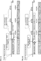
- FIGs. 1 show examples of discontinuous reception (DRX) control. Note that FIG. 1A shows a case where the user terminal transitions to the discontinuous reception (DRX) state upon expiration of the DRX-inactivity timer, and FIG. 1B shows a case where the user terminal transitions to discontinuous reception following a MAC control element (DRX command MAC control element) that commands a transition to the DRX state.
- DRX command MAC control element a MAC control element
- the DRX cycle specifies the cycle combining an ON duration and a sleep duration that follows the ON duration. Note that, in the ON duration, the user terminal assumes the active state and receives downlink signals such as the PDCCH. On the other hand, in the sleep duration, the user terminal stops receiving downlink signals such as the PDCCH.
- the user terminal when the user terminal successfully decodes the PDCCH for the user terminal in the ON duration, the user terminal starts a DRX-inactivity timer.
- the DRX-inactivity timer is a timer that measures a predetermined period after the PDCCH is successfully decoded.
- the user terminal continues assuming the active state until the DRX-inactivity timer expires, and, when the DRX-inactivity timer corresponding to the last PDCCH that was received expires, starts the above-mentioned DRX cycle (transitions to the discontinuous reception state). Also, when the user terminal successfully decodes the PDCCH for the user terminal before the DRX-inactivity timer expires, the user terminal re-starts the DRX-inactivity timer.
- the user terminal even before the DRX-inactivity timer expires, if the user terminal receives a predetermined MAC control element (DRX MAC CE: DRX command MAC Control Element), the user terminal starts the DRX cycle. That is, upon receiving the DRX MAC CE, the user terminal forces the DRX-inactivity timer to stop, and transitions to the discontinuous reception state. In this way, by using the DRX MAC CE, the radio base station can let the user terminal transition to the discontinuous reception state.
- DRX MAC CE DRX command MAC Control Element
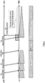
- the user terminal can be forced to transition to the DRX state only while DL allocation control is applied to the user terminal. Consequently, while UL allocation control is applied to the user terminal (while UL grants are transmitted), it is not possible to force the user terminal to transition to the discontinuous reception state (see FIG. 2 ).
- the user terminal assumes the active state for a predetermined period of time (for example, until the time the DRX-inactivity timer expires) from the time the UL grant is allocated, even if no data is transmitted/received after this.
- the present inventors have focused on the fact that the battery saving in user terminals after UL grant allocation control is not sufficient with conventional DRX control, and worked on the DRX control after UL grant allocation.
- a method to transmit the conventional DRX MAC CE shortly after a UL grant is allocated, and force a user terminal to transition to the discontinuous reception state may be possible (see FIG. 3 ).
- a DL signal needs to be transmitted only to let the user terminal transition to the discontinuous reception state, and there is a threat of leading to a decrease in the efficiency of the use of radio resources.
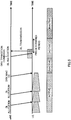
- the present inventors have come up with a control method to make the user terminal transition to the discontinuous reception state when UL allocation is commanded by using a UL grant (when a UL grant is transmitted).
- a UL grant is indicated to the user terminal, information to command whether or not to transition to the discontinuous reception state is reported together (DRX transition command information) (see FIG. 4 ).
- the user terminal having received the UL grant controls the discontinuous reception operations in accordance with the content of the DRX transition command information.
- the DRX transition command information may be information to indicate the timing to transition to the discontinuous reception state to the user terminal having received the UL grant, or information to command not to start or re-start the DRX-inactivity timer.
- the user terminal can transition to the discontinuous reception state shortly after receiving the UL grant.
- the power consumption of the user terminal can be reduced more in comparison to conventional DRX control. Also, it is no longer necessary to transmit DL signals only to command discontinuous reception to the user terminal, so that it is possible to reduce the decrease of the efficiency of the use of radio resources.
- DCI downlink control information
- MAC CE MAC control element
- DCI downlink control information
- a radio base station can command a DRX transition to a user terminal by using downlink control information (DCI) that includes a UL grant.
- DCI downlink control information
- the radio base station configures a bit field for DRX transition command information in downlink control information (DCI), and allocates this DCI to the downlink control channel (PDCCH).
- DCI formats 0, 4 and so on can be used as downlink control information.
- the user terminal receives the downlink control channel, in which the UL grant is included, and, furthermore, detects the bit that indicates whether or not to make a DRX transition (DRX transition command information).
- DRX transition command information When a transition to discontinuous reception is commanded in the downlink control information received, the user terminal transitions to the discontinuous reception state. For example, the user terminal does not start the DRX-inactivity timer, and transitions to the discontinuous reception state after the ON duration is over (see FIG. 4 ).
- the user terminal may be controlled to transition to the discontinuous reception state a predetermined period after the bit that corresponds to the DRX transition command information is detected, instead of transitioning to the discontinuous reception state soon (see FIG. 5 ).
- the predetermined period has only to be configured shorter than the duration of the DRX-inactivity timer.
- the user terminal having received a DRX transition command when the user terminal having received a DRX transition command additionally receives a command to start or re-start the DRX-inactivity timer before making a transition to discontinuous reception (for example, within the predetermined period shown in FIG. 5 ), the user terminal may cancel the transition operations to discontinuous reception triggered by the DRX transition command (see FIG. 6 ).
- the user terminal may cancel the transition operations to discontinuous reception triggered by the DRX transition command (see FIG. 6 ).
- the user terminal may be structured to cancel the transition operations to discontinuous reception only when the PDCCH to command a start or a re-start of the DRX-inactivity timer is received a predetermined number of times.
- the PDCCH detection failures false detection
- the user terminal may cancel the transition to discontinuous reception. That is, when the user terminal is unable to receive an ACK in response to the PUSCH, the user terminal can operate not to transition to DRX in expectation of a PDCCH retransmission from the radio base station. In this way, the transition operations to discontinuous reception is controlled by taking into consideration the positive delivery acknowledgement signal in response to the PUSCH signal, so that data can be transmitted/received adequately.
- ACK delivery acknowledgement signal
- PUSCH signal UL data signal
- DRX transition cancel operation in the user terminal may be controlled by the radio base station by using the RRC signal, the MAC signal and so on. By this means, it is possible to execute more flexible DRX control in the user terminal based on the state of communication.
- a user terminal operates to transition to discontinuous reception (DRX) when a DRX transition is commanded
- DRX discontinuous reception
- the radio base station when sending a UL grant, may also send a command for not starting or re-starting the DRX-inactivity timer to the user terminal together, by using downlink control information (DCI).
- DCI downlink control information
- the radio base station transmits downlink control information (DCI), which includes a UL grant, to the user terminal, by using the downlink control channel (PDCCH/EPDCCH). Meanwhile, the user terminal receives this downlink control information (UL grant) (ST101). Based on the UL grant received, the user terminal controls the transmission of UL data (PUSCH signal).
- DCI downlink control information
- UL grant downlink control information
- the user terminal decides whether a transition to discontinuous reception (DRX) is commanded in the downlink control information (DCI) received (ST102). For example, the user terminal detects the DRX transition command information included in the downlink control information, and decides whether or not to transition to the discontinuous reception state based on this DRX transition command information.
- DRX transition to discontinuous reception
- DCI downlink control information
- the user terminal transitions to the discontinuous reception state (ST103). For example, when a transition to the discontinuous reception state is commanded in the DRX transition command information, the user terminal transitions to the discontinuous reception state after transmitting UL data (PUSCH signal). When doing so, the user terminal may transition to the discontinuous reception state a predetermined period after the transition to discontinuous reception is commanded, as shown in above FIG. 5 .
- the user terminal may operate not to start or re-start the DRX-inactivity timer.
- the user terminal may cancel the transition operations to the discontinuous reception state. Also, even when a transition to the discontinuous reception state is commanded in ST102, if the user terminal is unable to receive the delivery acknowledgement signal (ACK) in response to the UL data signal (PUSCH signal) that has been transmitted based on the UL grant, the user terminal may cancel the transition to the discontinuous reception state.
- ACK delivery acknowledgement signal
- PUSCH signal UL data signal
- the user terminal When a transition to the discontinuous reception state is not commanded in the downlink control information (ST102: No), the user terminal starts or re-starts the DRX-inactivity timer (ST104). For example, when the radio base station further transmits/receives more data with respect to the user terminal, the radio base station commands the user terminal not to transition to the discontinuous reception (DRX) state, with downlink control information.
- MAC CE MAC control element
- the radio base station transmits a predetermined MAC CE that indicates a UL grant and a command for a DRX transition (for example, DRX command with UL grant MAC CE) to the user terminal.
- the user terminal upon receiving this predetermined MAC CE, performs UL transmission operations and transition operations to the DRX state (see FIG. 4 ).
- the user terminal when detecting a predetermined MAC CE to indicate a UL grant and a command for a DRX transition, the user terminal may be controlled to transition to the discontinuous reception state a predetermined period after the detection, instead of transitioning to the discontinuous reception state soon.
- the predetermined period has only to be configured shorter than the duration of the DRX-inactivity timer.
- the user terminal having received a predetermined MAC CE to indicate a UL grant and a DRX transition command additionally receives a command to start or re-start the DRX-inactivity timer before making a transition to discontinuous reception (for example, within the predetermined period shown in FIG. 5 )
- the user terminal may cancel the transition operations to discontinuous reception triggered by the DRX transition command (see FIG. 6 ).
- the user terminal may cancel the transition to the discontinuous reception. That is, when the user terminal is unable to receive an ACK in response to the PUSCH, the user terminal can operate not to transition to DRX in expectation of a PDCCH retransmission from the radio base station. In this way, the transition operations to discontinuous reception is controlled by taking into consideration the positive delivery acknowledgement signal in response to the PUSCH signal, so that data can be transmitted/received adequately.
- ACK delivery acknowledgement signal
- PUSCH signal UL data signal
- DRX transition stop operations in the user terminal may be controlled by the radio base station by using the RRC signal, the MAC signal and so on. By this means, it is possible to execute more flexible DRX control in the user terminal based on the state of communication.
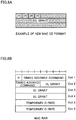
- a new MAC CE format can be used as a predetermined MAC CE to indicate a UL grant and a command for a DRX transition.
- a new MAC CE format (3 bytes) to include a UL grant can be used.
- the conventional MAC PDU Protocol Data Unit
- the conventional MAC PDU Protocol Data Unit
- RAR random access response
- the user terminal can interpret this RAR as a MAC CE to indicate a UL grant and a command for a DRX transition, and performs UL grant receiving operations and DRX transition operations.
- the user terminal is capable of transmission only by using the RA-RNTI (Random Access RNTI). Consequently, when, as shown above, the MAC RAR is used as a MAC CE to indicate a UL grant and a command for a DRX transition, the user terminal is controlled to operate in expectation of an RAR in response to the C-RNTI as well.
- RA-RNTI Random Access RNTI
- radio communication system according to the present embodiment will be described in detail below.
- the above-described radio communication methods according to the first and second examples are employed.
- the above radio communication methods according to the first and second examples may be applied individually or may be applied in combination.
- FIG. 9 is a schematic structure diagram of the radio communication system according to the present embodiment.
- the radio communication system 1 is comprised of a radio base station 10 that forms a cell C, user terminals 20 and a core network 30 with which the radio base station 10 is connected. Note that the number of radio base stations 10 and user terminals 20 is not limited to what is illustrated in FIG. 9 .
- the radio base station 10 and the user terminals 20 have hardware including a communication interface, a processor, a memory, a display and input keys, and, in the memory, software modules to be executed on the processor are stored. Also, the functional structures of the radio base station 10 and the user terminals 20 may be implemented by using the above-described hardware, may be implemented by using the software modules to be executed on the processor, or may be implemented by combining both of these.
- the radio base station 10 is a radio base station to have a predetermined coverage.
- the radio base station 10 may be a macro base station to have a relatively wide coverage (which may be an eNodeB, a macro base station, a central node, a transmission point, a transmitting/receiving point and so on), or may be a small base station to have a local coverage (which may be a small base station, a pico base station, a femto base station, an HeNB (Home eNodeB), an RRH (Remote Radio Head), a micro base station, a transmission point, a transmitting/receiving point and so on).
- the radio base station 10 is connected to the core network 30.
- core network devices such as an MME (Mobility Management Entity), an S-GW (Serving-GateWay), a P-GW (Packet-GateWay) and so on are provided.
- MME Mobility Management Entity
- S-GW Serving-GateWay
- P-GW Packet-GateWay
- the MME provided in the core network 30 is a device to perform mobility management for the user terminals 20, and may be connected to the radio base station 10 via a C-plane interface (for example, the S1-C interface).
- the S-GW provided in the core network 30 is a device to process the user data that is transmitted from the radio base station 10 to the user terminals 20, and may be connected with the radio base station 10 via a U-plane interface (for example, the S1-U interface).
- the user terminals 20 are terminals to support various communication schemes such as LTE, LTE-A and so on, and may be either mobile communication terminals or stationary communication terminals.
- the user terminals 20 carry out downlink/uplink communication with the radio base station 10.
- Downlink communication channels include a PDSCH (Physical Downlink Shared CHannel), which is used by each user terminal 20 on a shared basis, and downlink L1/L2 control channels (PDCCH, PCFICH, PHICH and enhanced PDCCH).
- PDSCH Physical Downlink Shared CHannel
- PDCCH Physical Downlink Control CHannel
- the number of OFDM symbols to use for the PDCCH is communicated by the PCFICH (Physical Control Format Indicator CHannel).
- HARQ ACKs/NACKs for the PUSCH are communicated by the PHICH (Physical Hybrid-ARQ Indicator CHannel). Also, the scheduling information for the PDSCH and the PUSCH and so on may be communicated by the enhanced PDCCH (EPDCCH) as well. This EPDCCH is frequency-division-multiplexed with the PDSCH (downlink shared data channel).
- PHICH Physical Hybrid-ARQ Indicator CHannel
- EPDCCH enhanced PDCCH
- Uplink communication channels include a PUSCH (Physical Uplink Shared CHannel), which is used by each user terminal 20 on a shared basis as an uplink data channel, and a PUCCH (Physical Uplink Control CHannel), which is an uplink control channel. User data and higher control information are communicated by this PUSCH. Also, downlink channel state information (CSI), ACK/NACK and so on are communicated by the PUCCH.
- PUSCH Physical Uplink Shared CHannel
- PUCCH Physical Uplink Control CHannel
- duplex scheme a frequency division duplex (FDD) scheme, a time division duplex (TDD) scheme, or both of these may be used.
- FDD frequency division duplex
- TDD time division duplex
- FIG. 10 is a diagram to show an overall structure of a radio base station 10 according to the present embodiment.
- the radio base station 10 has a plurality of transmitting/receiving antennas 101 for MIMO communication, amplifying sections 102, transmitting/receiving sections (transmission section/receiving section) 103, a baseband signal processing section 104, a call processing section 105 and a communication path interface 106.
- User data to be transmitted from the radio base station 10 to a user terminal 20 on the downlink is input from the higher station apparatus 30 to the baseband signal processing section 104, via the communication path interface 106.
- a PDCP layer process In the baseband signal processing section 104, a PDCP layer process, division and coupling of user data, RLC (Radio Link Control) layer transmission processes such as an RLC retransmission control transmission process, MAC (Medium Access Control) retransmission control, including, for example, an HARQ transmission process, scheduling, transport format selection, channel coding, an inverse fast Fourier transform (IFFT) process and a precoding process are performed, and the result is forwarded to each transmitting/receiving section 103. Furthermore, downlink control channel signals are also subjected to transmission processes such as channel coding and an inverse fast Fourier transform, and forwarded to each transmitting/receiving section 103.
- RLC Radio Link Control
- MAC Medium Access Control
- the baseband signal processing section 104 reports information (DRX transition command information) that allows the user terminal 20 to control the discontinuous reception operations (the transition operations to discontinuous reception).
- the DRX transition command information can be reported to the user terminal by using downlink control information (for example, DCI to include a UL grant), a predetermined MAC CE (MAC CE to command DRX) and so on.
- Each transmitting/receiving section 103 converts the baseband signals, which are pre-coded and output from the baseband signal processing section 104 on a per antenna basis, into a radio frequency band.
- the amplifying sections 102 amplify the radio frequency signals having been subjected to frequency conversion, and transmit the signals through the transmitting/receiving antennas 101.
- the transmitting/receiving sections 103 function as transmission sections to transmit DL signals that at least include UL grants and DRX transition command information.
- radio frequency signals that are received in the transmitting/receiving antennas 101 are each amplified in the amplifying sections 102, converted into the baseband signal through frequency conversion in each transmitting/receiving section 103, and input in the baseband signal processing section 104.
- the user data that is included in the input baseband signal is subjected to an FFT process, an IDFT process, error correction decoding, a MAC retransmission control receiving process, and RLC layer and PDCP layer receiving processes, and the result is forwarded to the core network 30 via the communication path interface 106.
- the call processing section 105 performs call processing such as setting up and releasing communication channels, manages the state of the radio base stations 10 and manages the radio resources.
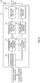
- FIG. 11 is a diagram to show a principle functional structure of the baseband signal processing section 104 provided in the radio base station 10 according to the present embodiment.
- the baseband signal processing section 104 provided in the radio base station 10 is comprised at least of a control section 301, a DL signal generating section 302, a mapping section 303, a UL signal demodulation section 304 and a decision section 305.
- the control section 301 controls the scheduling of downlink user data that is transmitted in the PDSCH, downlink control information that is transmitted in the PDCCH and/or the enhanced PDCCH (EPDCCH), downlink reference signals and so on (DL allocation control). Also, the control section 301 controls the scheduling of uplink data that is transmitted in the PUSCH, uplink control information that is transmitted in the PUCCH or the PUSCH, and uplink reference signals (UL allocation control). Information about the allocation control of uplink signals (uplink control signals and uplink user data) is reported to user terminals by using downlink control signals (DCI).
- DCI downlink control signals
- control section 301 controls the allocation of radio resources to downlink signals and uplink signals based on command information from the core network 30, feedback information from each user terminal 20 and so on. That is, the control section 301 functions as a scheduler. Also, the control section 301 can also control the discontinuous reception (DRX) operations in user terminals.
- DRX discontinuous reception
- control section 301 when carrying out UL allocation and also making a user terminal transition to the discontinuous reception state, commands the DL signal generating section 302 to generate a UL grant and information related to a command for a transition to the discontinuous reception state (DRX transition command information).
- DRX transition command information information related to a command for a transition to the discontinuous reception state
- the DL signal generating section 302 generates a MAC control element (MAC CE), a physical downlink channel signal, and so on.
- MAC CE MAC control element
- the DL signal generating section 302 generates a downlink control signal (PDCCH signal and/or EPDCCH signal), a downlink data signal (PDSCH signal) and so on, determined to be allocated by the control section 301.
- the DL signal generating section 302 Based on commands from the control section 301, the DL signal generating section 302 generates DL assignments, which report downlink signal allocation information, and UL grants, which report uplink signal allocation information.
- the DL signal generating section 302 generates a PDCCH signal that includes a UL grant and information related to a command for a transition to the discontinuous reception state (DRX transition command information), or a predetermined MAC CE (for example, DRX command with UL grant MAC CE).
- DRX transition command information information related to a command for a transition to the discontinuous reception state
- a predetermined MAC CE for example, DRX command with UL grant MAC CE.
- the DL signal generating section 302 can use the MAC CE formats shown in above FIGs. 8 .
- the mapping section 303 controls the allocation of the downlink control signals and the downlink data signals generated in the DL signal generating section 302 to radio resources based on commands from the control section 301.
- the UL signal demodulation section 304 demodulates the feedback signals (delivery acknowledgement signals and/or the like) transmitted from the user terminal through an uplink control channel (PUCCH), and outputs the results to the control section 301. Also, the UL signal demodulation section 304 demodulates the uplink data signals transmitted from the user terminal through an uplink shared channel (PUSCH), and outputs the results to the decision section 305.
- PUCCH uplink control channel
- PUSCH uplink shared channel
- the decision section 305 makes retransmission control decisions (ACKs/NACKs) based on the demodulation results in the UL signal demodulation section 304, and, furthermore, outputs the results to the control section 301. Note that the results made in the decision section 305 (delivery acknowledgement signals) are reported to the user terminal by using the PHICH (Physical Hybrid-ARQ Indicator CHannel).
- PHICH Physical Hybrid-ARQ Indicator CHannel
- FIG. 12 is a diagram to show an overall structure of a user terminal 20 according to the present embodiment.
- the user terminal 20 has a plurality of transmitting/receiving antennas 201 for MIMO communication, amplifying sections 202, transmitting/receiving sections (transmitting section/receiving section) 203, a baseband signal processing section 204 and an application section 205.
- radio frequency signals that are received in a plurality of transmitting/receiving antennas 201 are each amplified in the amplifying sections 202, and subjected to frequency conversion and converted into the baseband signal in the transmitting/receiving sections 203.
- This baseband signal is subjected to receiving processes such as an FFT process, error correction decoding and retransmission control, in the baseband signal processing section 204.
- downlink user data is forwarded to the application section 205.
- the application section 205 performs processes related to higher layers above the physical layer and the MAC layer.
- broadcast information is also forwarded to the application section 205.
- the transmitting/receiving sections 203 function as receiving sections to receive DL signals that include UL grants and DRX transition command information.
- uplink user data is input from the application section 205 to the baseband signal processing section 204.
- a retransmission control (H-ARQ (Hybrid ARQ)) transmission process channel coding, precoding, a DFT process, an IFFT process and so on are performed, and the result is forwarded to each transmitting/receiving section 203.
- the baseband signal that is output from the baseband signal processing section 204 is converted into a radio frequency band in the transmitting/receiving sections 203.
- the amplifying sections 202 amplify the radio frequency signal having been subjected to frequency conversion, and transmit the resulting signal from the transmitting/receiving antennas 201.
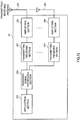
- FIG. 13 is a diagram to show a principle functional structure of the baseband signal processing section 204 (which may include the application section 205) provided in the user terminal 20.
- the baseband signal processing section 204 provided in the user terminal 20 is comprised at least of a DL signal demodulation section 401, a DRX control section 402 (a timer management section 402a and a DRX state management section 402b), a control section (feedback control section) 403, a UL signal generating section 404 and a mapping section 405.
- the DL signal demodulation section 401 demodulates the downlink control signal (PDCCH signal) transmitted in the downlink control channel (PDCCH), and outputs the scheduling information (information regarding the allocation to uplink resources) to the DRX control section 402 and the control section 403. Also, the DL signal demodulation section 401 demodulates the downlink data signal transmitted in the downlink shared channel (PDSCH).
- PDSCH downlink shared channel
- the DRX control section 402 has a timer management section 402a and a DRX state management section 402b, and controls the discontinuous reception (DRX) operations in the user terminal.
- the timer management section 402a manages a predetermined timer (for example, a DRX-inactivity timer) pertaining to DRX operations. For example, when the DRX-inactivity timer expires, the timer management section 402a sends a report to the DRX state management section 402b.
- the DRX state management section 402b manages the DRX state (transition to the DRX state and so on) in the user terminal.
- the DRX control section 402 when receiving a DL signal that includes a UL grant, controls the application of discontinuous reception based on the DRX transition command information included in this DL signal.
- the DRX control section 402 can apply control so that a transition is made to the discontinuous reception state after a predetermined period (see above FIG. 5 ).
- the DRX control section 402 may cancel the transition to the discontinuous reception state (see above FIG. 6 ).
- the DRX control section 402 may cancel the transition to the discontinuous reception state.
- the control section 403 controls the generation of uplink control signals (feedback signals) and uplink data signals based on downlink control signals (PDCCH signal) transmitted from the radio base station, retransmission control decisions in response to the PDSCH signals that have been received, and so on. Also, the control section 403 also functions as a feedback control section that controls the feedback of delivery acknowledgement signals (A/N's) in response to PDSCH signals. Note that when the DRX control section 402 decides to make a transition to the discontinuous reception state, the control section 403 stops operating.
- the UL signal generating section 404 generates uplink control signals (feedback signals such as delivery acknowledgement signals, channel state information (CSI) and so on) based on commands from the control section 403. Also, the UL signal generating section 404 generates uplink data signals based on commands from the control section 403.
- uplink control signals feedback signals such as delivery acknowledgement signals, channel state information (CSI) and so on
- CSI channel state information
- the mapping section 405 controls the allocation of uplink control signals (delivery acknowledgement signals, etc.) and uplink data signals to radio resources (the PUCCH and the PUSCH) based on commands from the control section 405.
Landscapes
- Engineering & Computer Science (AREA)
- Computer Networks & Wireless Communication (AREA)
- Signal Processing (AREA)
- Mobile Radio Communication Systems (AREA)
- Circuits Of Receivers In General (AREA)
Applications Claiming Priority (2)
| Application Number | Priority Date | Filing Date | Title |
|---|---|---|---|
| JP2014101526 | 2014-05-15 | ||
| PCT/JP2015/063245 WO2015174327A1 (fr) | 2014-05-15 | 2015-05-08 | Terminal utilisateur, station de base sans fil et procédé de communication sans fil |
Publications (3)
| Publication Number | Publication Date |
|---|---|
| EP3145251A1 true EP3145251A1 (fr) | 2017-03-22 |
| EP3145251A4 EP3145251A4 (fr) | 2017-12-20 |
| EP3145251B1 EP3145251B1 (fr) | 2021-11-17 |
Family
ID=54479868
Family Applications (1)
| Application Number | Title | Priority Date | Filing Date |
|---|---|---|---|
| EP15792280.8A Active EP3145251B1 (fr) | 2014-05-15 | 2015-05-08 | Terminal utilisateur, station de base sans fil et procédé de communication sans fil |
Country Status (8)
| Country | Link |
|---|---|
| US (1) | US20170099635A1 (fr) |
| EP (1) | EP3145251B1 (fr) |
| JP (1) | JP6174249B2 (fr) |
| CN (1) | CN106465270B (fr) |
| CL (1) | CL2016002897A1 (fr) |
| DK (1) | DK3145251T3 (fr) |
| HU (1) | HUE056951T2 (fr) |
| WO (1) | WO2015174327A1 (fr) |
Cited By (2)
| Publication number | Priority date | Publication date | Assignee | Title |
|---|---|---|---|---|
| WO2018060804A1 (fr) * | 2016-09-29 | 2018-04-05 | Telefonaktiebolaget Lm Ericsson (Publ) | Gestion de temps active comportant une autorisation en deux étapes |
| EP3565319A4 (fr) * | 2017-01-10 | 2019-11-06 | Guangdong OPPO Mobile Telecommunications Corp., Ltd. | Procédé de détermination d'état de réception discontinu, dispositif terminal et dispositif de réseau |
Families Citing this family (14)
| Publication number | Priority date | Publication date | Assignee | Title |
|---|---|---|---|---|
| US20170359780A1 (en) * | 2016-06-10 | 2017-12-14 | Apple Inc. | Device, System, and Method for Adaptive Monitoring to Optimize Power Consumption |
| US20180279357A1 (en) * | 2017-03-21 | 2018-09-27 | Qualcomm Incorporated | Techniques and apparatuses for temporary modification of periodic grants |
| US20200068598A1 (en) * | 2017-05-02 | 2020-02-27 | Ntt Docomo, Inc. | User terminal and radio communication method |
| CN110603860B (zh) | 2017-05-04 | 2022-12-02 | Oppo广东移动通信有限公司 | 用于非连续接收的方法和设备 |
| JP7046926B2 (ja) * | 2017-05-12 | 2022-04-04 | 株式会社Nttドコモ | 端末、無線通信方法、基地局及びシステム |
| CN110999501B (zh) * | 2017-06-08 | 2023-11-07 | 株式会社Ntt都科摩 | 用户终端以及无线通信方法 |
| US10609700B2 (en) * | 2017-06-15 | 2020-03-31 | Apple Inc. | Control channel for UE power saving |
| WO2019136645A1 (fr) * | 2018-01-10 | 2019-07-18 | Oppo广东移动通信有限公司 | Procédé pour déterminer l'état d'un dispositif de terminal, dispositif de terminal et dispositif de réseau d'accès |
| CN118612827A (zh) * | 2018-08-10 | 2024-09-06 | 中兴通讯股份有限公司 | 无线通信方法、通信设备及存储介质 |
| JP7531491B2 (ja) | 2019-01-08 | 2024-08-09 | ペキン シャオミ モバイル ソフトウェア カンパニー, リミテッド | 省電力メカニズム |
| CN113796040B (zh) * | 2019-05-03 | 2024-02-23 | Lg电子株式会社 | 在无线通信系统中发送和接收信号的方法和装置 |
| WO2020252705A1 (fr) * | 2019-06-19 | 2020-12-24 | Oppo广东移动通信有限公司 | Procédé et appareil de commande d'état de communication, terminal et dispositif de réseau |
| CN112738903B (zh) * | 2019-10-28 | 2022-08-09 | 普天信息技术有限公司 | Drx实现方法、用户终端及基站 |
| JPWO2023277079A1 (fr) * | 2021-06-29 | 2023-01-05 |
Family Cites Families (24)
| Publication number | Priority date | Publication date | Assignee | Title |
|---|---|---|---|---|
| US7957360B2 (en) * | 2007-01-09 | 2011-06-07 | Motorola Mobility, Inc. | Method and system for the support of a long DRX in an LTE—active state in a wireless network |
| EP2028780A1 (fr) * | 2007-08-20 | 2009-02-25 | Research In Motion Limited | Système et procédé de retransmissions dans un système configuré de réception discontinue |
| WO2009088496A1 (fr) * | 2008-01-04 | 2009-07-16 | Nokia Siemens Networks Oy | Système et procédé pour un fonctionnement d'émetteur-récepteur semi-duplex efficace dans un système de communication sans fil par paquets |
| US8488521B2 (en) * | 2008-03-14 | 2013-07-16 | Interdigital Patent Holdings, Inc. | Behavior for wireless transmit/receive unit and MAC control elements for LTE DRX operations |
| WO2009116912A1 (fr) * | 2008-03-19 | 2009-09-24 | Telefonaktiebolaget L M Ericsson (Publ) | Procédé et station de base destinés à détecter la perte de synchronisation |
| US8462803B2 (en) * | 2008-05-07 | 2013-06-11 | Telefonaktiebolaget L M Ericsson (Publ) | Discontinuous reception (DRX) timer triggered with the transmission of a buffer status report (BSR) |
| WO2010048178A1 (fr) * | 2008-10-20 | 2010-04-29 | Interdigital Patent Holdings, Inc. | Regroupement de porteuses |
| US20110002281A1 (en) * | 2008-12-30 | 2011-01-06 | Interdigital Patent Holdings, Inc. | Discontinuous reception for carrier aggregation |
| CN102123399B (zh) * | 2010-01-08 | 2014-01-01 | 华为技术有限公司 | 调度请求的方法及装置 |
| CN105306186A (zh) * | 2010-05-25 | 2016-02-03 | 交互数字专利控股公司 | 一种由wtru操作的方法及wtru |
| KR101489873B1 (ko) * | 2010-06-30 | 2015-02-05 | 노키아 솔루션스 앤드 네트웍스 오와이 | 통신 네트워크에서의 사용자 단말들의 스케줄링 |
| KR20130041969A (ko) * | 2010-07-26 | 2013-04-25 | 노키아 지멘스 네트웍스 오와이 | 통신 네트워크 내에서의 데이터 처리를 위한 방법 및 디바이스 |
| EP2692073B1 (fr) * | 2011-03-31 | 2018-10-17 | LG Electronics Inc. | Procédé et appareil pour surveiller un canal de contrôle sur la liaison descendante |
| CN102761942B (zh) * | 2011-04-29 | 2015-01-21 | 华为技术有限公司 | 状态切换方法、非激活定时器启动方法和用户设备 |
| KR102172436B1 (ko) * | 2011-10-12 | 2020-10-30 | 삼성전자주식회사 | 이동통신 시스템에서 역방향 제어 신호를 전송하는 방법 및 장치 |
| JP5792580B2 (ja) * | 2011-10-14 | 2015-10-14 | 株式会社Nttドコモ | 基地局及び通信制御方法 |
| US9363799B2 (en) * | 2011-10-31 | 2016-06-07 | Lg Electronics Inc. | Method for transmitting an uplink control signal, user equipment, method for receiving an uplink signal, and base station |
| EP2621242A1 (fr) * | 2012-01-26 | 2013-07-31 | Panasonic Corporation | Opération de réception discontinue améliorée dotée d'opportunités d'éveil supplémentaire |
| CN102595573A (zh) * | 2012-02-02 | 2012-07-18 | 电信科学技术研究院 | 一种配置drx参数的方法、系统和设备 |
| KR101868865B1 (ko) * | 2012-03-19 | 2018-06-19 | 주식회사 골드피크이노베이션즈 | 무선통신 시스템에서 기기 내 공존 간섭을 제어하는 장치 및 방법 |
| JP5842715B2 (ja) * | 2012-03-30 | 2016-01-13 | 富士通株式会社 | 間欠受信制御装置、間欠受信制御プログラム及び間欠受信制御方法 |
| US9271234B2 (en) * | 2012-08-03 | 2016-02-23 | Sony Corporation | Terminal requested base station controlled terminal transmission throttling |
| US8755318B2 (en) * | 2012-09-05 | 2014-06-17 | Apple Inc. | Synchronizing uplink and downlink transmissions in a wireless device |
| US20140269475A1 (en) * | 2013-03-14 | 2014-09-18 | Qualcomm Incorporated | Apparatus and method for optimizing uplink semi-persistent scheduling activation |
-
2015
- 2015-05-08 CN CN201580025302.7A patent/CN106465270B/zh active Active
- 2015-05-08 HU HUE15792280A patent/HUE056951T2/hu unknown
- 2015-05-08 DK DK15792280.8T patent/DK3145251T3/da active
- 2015-05-08 US US15/311,092 patent/US20170099635A1/en not_active Abandoned
- 2015-05-08 WO PCT/JP2015/063245 patent/WO2015174327A1/fr active Application Filing
- 2015-05-08 EP EP15792280.8A patent/EP3145251B1/fr active Active
- 2015-05-08 JP JP2016519226A patent/JP6174249B2/ja active Active
-
2016
- 2016-11-14 CL CL2016002897A patent/CL2016002897A1/es unknown
Cited By (3)
| Publication number | Priority date | Publication date | Assignee | Title |
|---|---|---|---|---|
| WO2018060804A1 (fr) * | 2016-09-29 | 2018-04-05 | Telefonaktiebolaget Lm Ericsson (Publ) | Gestion de temps active comportant une autorisation en deux étapes |
| EP3565319A4 (fr) * | 2017-01-10 | 2019-11-06 | Guangdong OPPO Mobile Telecommunications Corp., Ltd. | Procédé de détermination d'état de réception discontinu, dispositif terminal et dispositif de réseau |
| US11096238B2 (en) | 2017-01-10 | 2021-08-17 | Guangdong Oppo Mobile Telecommunications Corp., Ltd. | Method for determining a discontinuous reception state, terminal device and network device |
Also Published As
| Publication number | Publication date |
|---|---|
| CN106465270A (zh) | 2017-02-22 |
| US20170099635A1 (en) | 2017-04-06 |
| EP3145251B1 (fr) | 2021-11-17 |
| CL2016002897A1 (es) | 2017-07-14 |
| WO2015174327A1 (fr) | 2015-11-19 |
| JP6174249B2 (ja) | 2017-08-02 |
| EP3145251A4 (fr) | 2017-12-20 |
| JPWO2015174327A1 (ja) | 2017-04-20 |
| HUE056951T2 (hu) | 2022-03-28 |
| CN106465270B (zh) | 2020-07-21 |
| DK3145251T3 (da) | 2021-12-06 |
Similar Documents
| Publication | Publication Date | Title |
|---|---|---|
| EP3145251B1 (fr) | Terminal utilisateur, station de base sans fil et procédé de communication sans fil | |
| US11470680B2 (en) | Method for controlling connected mode DRX operations | |
| US10440756B2 (en) | Techniques for downlink scheduling and uplink scheduling in a shared radio frequency spectrum band | |
| CN113767699A (zh) | 确定用于物理下行链路控制信道(pdcch)监测的搜索空间集的方法和设备 | |
| US9860007B2 (en) | User terminal, radio base station, and radio communication method | |
| CN112602283A (zh) | 用于下行链路控制信道的下行链路指派 | |
| WO2019193700A1 (fr) | Terminal utilisateur et station de base sans fil | |
| EP3544221A1 (fr) | Configuration dynamique de ressources de trames en liaison montante (ul) et descendante (dl) pour une transmission avec duplexage par répartition dans le temps (tdd) | |
| EP3837902B1 (fr) | Système et procédé destinés à une réception de canal de commande en mode d'économie d'énergie | |
| US20150201456A1 (en) | Method and apparatus for configuring a discontinuous reception (drx) operation in a wireless communication system | |
| JP2015522228A (ja) | 無線通信システムにおけるdrx動作によるアップリンク送信を制御する方法および装置 | |
| JP6382499B2 (ja) | 無線基地局、ユーザ端末及び無線通信方法 | |
| WO2022218369A1 (fr) | Procédé de détermination de ressource de rétroinformation de liaison latérale, terminal, et dispositif côté réseau | |
| US20230145663A1 (en) | System and Method for Control Channel Reception in Power Save Mode | |
| WO2022146658A1 (fr) | Surveillance de canal de commande descendant pour services de multidiffusion/diffusion | |
| EP3123647B1 (fr) | Amélioration de services de communication de groupe | |
| WO2022234796A1 (fr) | Dispositif de communication, station de base et procédé de communication | |
| WO2022234838A1 (fr) | Dispositif de communication, station de base et procédé | |
| EP4383626A1 (fr) | Procédé et appareil de détermination d'informations de faisceau, et dispositif de communication et support de stockage | |
| WO2022234834A1 (fr) | Dispositif de communication, station de base et procédé | |
| WO2022234801A1 (fr) | Dispositif de communication, station de base et procédé de communication | |
| WO2022234835A1 (fr) | Équipement utilisateur, station de base et procédé de commande de communication |
Legal Events
| Date | Code | Title | Description |
|---|---|---|---|
| STAA | Information on the status of an ep patent application or granted ep patent |
Free format text: STATUS: THE INTERNATIONAL PUBLICATION HAS BEEN MADE |
|
| PUAI | Public reference made under article 153(3) epc to a published international application that has entered the european phase |
Free format text: ORIGINAL CODE: 0009012 |
|
| STAA | Information on the status of an ep patent application or granted ep patent |
Free format text: STATUS: REQUEST FOR EXAMINATION WAS MADE |
|
| 17P | Request for examination filed |
Effective date: 20161130 |
|
| AK | Designated contracting states |
Kind code of ref document: A1 Designated state(s): AL AT BE BG CH CY CZ DE DK EE ES FI FR GB GR HR HU IE IS IT LI LT LU LV MC MK MT NL NO PL PT RO RS SE SI SK SM TR |
|
| AX | Request for extension of the european patent |
Extension state: BA ME |
|
| DAV | Request for validation of the european patent (deleted) | ||
| DAX | Request for extension of the european patent (deleted) | ||
| A4 | Supplementary search report drawn up and despatched |
Effective date: 20171122 |
|
| RIC1 | Information provided on ipc code assigned before grant |
Ipc: H04W 52/02 20090101AFI20171116BHEP Ipc: H04W 72/14 20090101ALI20171116BHEP |
|
| STAA | Information on the status of an ep patent application or granted ep patent |
Free format text: STATUS: EXAMINATION IS IN PROGRESS |
|
| 17Q | First examination report despatched |
Effective date: 20190724 |
|
| STAA | Information on the status of an ep patent application or granted ep patent |
Free format text: STATUS: EXAMINATION IS IN PROGRESS |
|
| GRAP | Despatch of communication of intention to grant a patent |
Free format text: ORIGINAL CODE: EPIDOSNIGR1 |
|
| STAA | Information on the status of an ep patent application or granted ep patent |
Free format text: STATUS: GRANT OF PATENT IS INTENDED |
|
| INTG | Intention to grant announced |
Effective date: 20210723 |
|
| GRAS | Grant fee paid |
Free format text: ORIGINAL CODE: EPIDOSNIGR3 |
|
| GRAA | (expected) grant |
Free format text: ORIGINAL CODE: 0009210 |
|
| STAA | Information on the status of an ep patent application or granted ep patent |
Free format text: STATUS: THE PATENT HAS BEEN GRANTED |
|
| AK | Designated contracting states |
Kind code of ref document: B1 Designated state(s): AL AT BE BG CH CY CZ DE DK EE ES FI FR GB GR HR HU IE IS IT LI LT LU LV MC MK MT NL NO PL PT RO RS SE SI SK SM TR |
|
| REG | Reference to a national code |
Ref country code: GB Ref legal event code: FG4D |
|
| REG | Reference to a national code |
Ref country code: DE Ref legal event code: R096 Ref document number: 602015075105 Country of ref document: DE |
|
| REG | Reference to a national code |
Ref country code: DK Ref legal event code: T3 Effective date: 20211203 |
|
| REG | Reference to a national code |
Ref country code: IE Ref legal event code: FG4D |
|
| REG | Reference to a national code |
Ref country code: AT Ref legal event code: REF Ref document number: 1449058 Country of ref document: AT Kind code of ref document: T Effective date: 20211215 |
|
| REG | Reference to a national code |
Ref country code: NL Ref legal event code: FP |
|
| REG | Reference to a national code |
Ref country code: LT Ref legal event code: MG9D |
|
| REG | Reference to a national code |
Ref country code: HU Ref legal event code: AG4A Ref document number: E056951 Country of ref document: HU |
|
| REG | Reference to a national code |
Ref country code: AT Ref legal event code: MK05 Ref document number: 1449058 Country of ref document: AT Kind code of ref document: T Effective date: 20211117 |
|
| PG25 | Lapsed in a contracting state [announced via postgrant information from national office to epo] |
Ref country code: RS Free format text: LAPSE BECAUSE OF FAILURE TO SUBMIT A TRANSLATION OF THE DESCRIPTION OR TO PAY THE FEE WITHIN THE PRESCRIBED TIME-LIMIT Effective date: 20211117 Ref country code: LT Free format text: LAPSE BECAUSE OF FAILURE TO SUBMIT A TRANSLATION OF THE DESCRIPTION OR TO PAY THE FEE WITHIN THE PRESCRIBED TIME-LIMIT Effective date: 20211117 Ref country code: FI Free format text: LAPSE BECAUSE OF FAILURE TO SUBMIT A TRANSLATION OF THE DESCRIPTION OR TO PAY THE FEE WITHIN THE PRESCRIBED TIME-LIMIT Effective date: 20211117 Ref country code: BG Free format text: LAPSE BECAUSE OF FAILURE TO SUBMIT A TRANSLATION OF THE DESCRIPTION OR TO PAY THE FEE WITHIN THE PRESCRIBED TIME-LIMIT Effective date: 20220217 Ref country code: AT Free format text: LAPSE BECAUSE OF FAILURE TO SUBMIT A TRANSLATION OF THE DESCRIPTION OR TO PAY THE FEE WITHIN THE PRESCRIBED TIME-LIMIT Effective date: 20211117 |
|
| PG25 | Lapsed in a contracting state [announced via postgrant information from national office to epo] |
Ref country code: IS Free format text: LAPSE BECAUSE OF FAILURE TO SUBMIT A TRANSLATION OF THE DESCRIPTION OR TO PAY THE FEE WITHIN THE PRESCRIBED TIME-LIMIT Effective date: 20220317 Ref country code: SE Free format text: LAPSE BECAUSE OF FAILURE TO SUBMIT A TRANSLATION OF THE DESCRIPTION OR TO PAY THE FEE WITHIN THE PRESCRIBED TIME-LIMIT Effective date: 20211117 Ref country code: PT Free format text: LAPSE BECAUSE OF FAILURE TO SUBMIT A TRANSLATION OF THE DESCRIPTION OR TO PAY THE FEE WITHIN THE PRESCRIBED TIME-LIMIT Effective date: 20220317 Ref country code: PL Free format text: LAPSE BECAUSE OF FAILURE TO SUBMIT A TRANSLATION OF THE DESCRIPTION OR TO PAY THE FEE WITHIN THE PRESCRIBED TIME-LIMIT Effective date: 20211117 Ref country code: NO Free format text: LAPSE BECAUSE OF FAILURE TO SUBMIT A TRANSLATION OF THE DESCRIPTION OR TO PAY THE FEE WITHIN THE PRESCRIBED TIME-LIMIT Effective date: 20220217 Ref country code: LV Free format text: LAPSE BECAUSE OF FAILURE TO SUBMIT A TRANSLATION OF THE DESCRIPTION OR TO PAY THE FEE WITHIN THE PRESCRIBED TIME-LIMIT Effective date: 20211117 Ref country code: HR Free format text: LAPSE BECAUSE OF FAILURE TO SUBMIT A TRANSLATION OF THE DESCRIPTION OR TO PAY THE FEE WITHIN THE PRESCRIBED TIME-LIMIT Effective date: 20211117 Ref country code: GR Free format text: LAPSE BECAUSE OF FAILURE TO SUBMIT A TRANSLATION OF THE DESCRIPTION OR TO PAY THE FEE WITHIN THE PRESCRIBED TIME-LIMIT Effective date: 20220218 Ref country code: ES Free format text: LAPSE BECAUSE OF FAILURE TO SUBMIT A TRANSLATION OF THE DESCRIPTION OR TO PAY THE FEE WITHIN THE PRESCRIBED TIME-LIMIT Effective date: 20211117 |
|
| PG25 | Lapsed in a contracting state [announced via postgrant information from national office to epo] |
Ref country code: SM Free format text: LAPSE BECAUSE OF FAILURE TO SUBMIT A TRANSLATION OF THE DESCRIPTION OR TO PAY THE FEE WITHIN THE PRESCRIBED TIME-LIMIT Effective date: 20211117 Ref country code: SK Free format text: LAPSE BECAUSE OF FAILURE TO SUBMIT A TRANSLATION OF THE DESCRIPTION OR TO PAY THE FEE WITHIN THE PRESCRIBED TIME-LIMIT Effective date: 20211117 Ref country code: RO Free format text: LAPSE BECAUSE OF FAILURE TO SUBMIT A TRANSLATION OF THE DESCRIPTION OR TO PAY THE FEE WITHIN THE PRESCRIBED TIME-LIMIT Effective date: 20211117 Ref country code: CZ Free format text: LAPSE BECAUSE OF FAILURE TO SUBMIT A TRANSLATION OF THE DESCRIPTION OR TO PAY THE FEE WITHIN THE PRESCRIBED TIME-LIMIT Effective date: 20211117 |
|
| REG | Reference to a national code |
Ref country code: DE Ref legal event code: R097 Ref document number: 602015075105 Country of ref document: DE |
|
| PLBE | No opposition filed within time limit |
Free format text: ORIGINAL CODE: 0009261 |
|
| STAA | Information on the status of an ep patent application or granted ep patent |
Free format text: STATUS: NO OPPOSITION FILED WITHIN TIME LIMIT |
|
| 26N | No opposition filed |
Effective date: 20220818 |
|
| PG25 | Lapsed in a contracting state [announced via postgrant information from national office to epo] |
Ref country code: AL Free format text: LAPSE BECAUSE OF FAILURE TO SUBMIT A TRANSLATION OF THE DESCRIPTION OR TO PAY THE FEE WITHIN THE PRESCRIBED TIME-LIMIT Effective date: 20211117 |
|
| PG25 | Lapsed in a contracting state [announced via postgrant information from national office to epo] |
Ref country code: SI Free format text: LAPSE BECAUSE OF FAILURE TO SUBMIT A TRANSLATION OF THE DESCRIPTION OR TO PAY THE FEE WITHIN THE PRESCRIBED TIME-LIMIT Effective date: 20211117 |
|
| REG | Reference to a national code |
Ref country code: CH Ref legal event code: PL |
|
| PG25 | Lapsed in a contracting state [announced via postgrant information from national office to epo] |
Ref country code: MC Free format text: LAPSE BECAUSE OF FAILURE TO SUBMIT A TRANSLATION OF THE DESCRIPTION OR TO PAY THE FEE WITHIN THE PRESCRIBED TIME-LIMIT Effective date: 20211117 Ref country code: LU Free format text: LAPSE BECAUSE OF NON-PAYMENT OF DUE FEES Effective date: 20220508 Ref country code: LI Free format text: LAPSE BECAUSE OF NON-PAYMENT OF DUE FEES Effective date: 20220531 Ref country code: CH Free format text: LAPSE BECAUSE OF NON-PAYMENT OF DUE FEES Effective date: 20220531 |
|
| PG25 | Lapsed in a contracting state [announced via postgrant information from national office to epo] |
Ref country code: IE Free format text: LAPSE BECAUSE OF NON-PAYMENT OF DUE FEES Effective date: 20220508 |
|
| P01 | Opt-out of the competence of the unified patent court (upc) registered |
Effective date: 20230509 |
|
| PGFP | Annual fee paid to national office [announced via postgrant information from national office to epo] |
Ref country code: DE Payment date: 20230519 Year of fee payment: 9 |
|
| PG25 | Lapsed in a contracting state [announced via postgrant information from national office to epo] |
Ref country code: MK Free format text: LAPSE BECAUSE OF FAILURE TO SUBMIT A TRANSLATION OF THE DESCRIPTION OR TO PAY THE FEE WITHIN THE PRESCRIBED TIME-LIMIT Effective date: 20211117 Ref country code: EE Free format text: LAPSE BECAUSE OF FAILURE TO SUBMIT A TRANSLATION OF THE DESCRIPTION OR TO PAY THE FEE WITHIN THE PRESCRIBED TIME-LIMIT Effective date: 20211117 Ref country code: CY Free format text: LAPSE BECAUSE OF FAILURE TO SUBMIT A TRANSLATION OF THE DESCRIPTION OR TO PAY THE FEE WITHIN THE PRESCRIBED TIME-LIMIT Effective date: 20211117 |
|
| PGFP | Annual fee paid to national office [announced via postgrant information from national office to epo] |
Ref country code: NL Payment date: 20240521 Year of fee payment: 10 |
|
| PGFP | Annual fee paid to national office [announced via postgrant information from national office to epo] |
Ref country code: GB Payment date: 20240521 Year of fee payment: 10 |
|
| PGFP | Annual fee paid to national office [announced via postgrant information from national office to epo] |
Ref country code: DK Payment date: 20240527 Year of fee payment: 10 |
|
| PGFP | Annual fee paid to national office [announced via postgrant information from national office to epo] |
Ref country code: FR Payment date: 20240528 Year of fee payment: 10 |
|
| PGFP | Annual fee paid to national office [announced via postgrant information from national office to epo] |
Ref country code: HU Payment date: 20240523 Year of fee payment: 10 Ref country code: BE Payment date: 20240521 Year of fee payment: 10 |
|
| PG25 | Lapsed in a contracting state [announced via postgrant information from national office to epo] |
Ref country code: MT Free format text: LAPSE BECAUSE OF FAILURE TO SUBMIT A TRANSLATION OF THE DESCRIPTION OR TO PAY THE FEE WITHIN THE PRESCRIBED TIME-LIMIT Effective date: 20211117 |
|
| PGFP | Annual fee paid to national office [announced via postgrant information from national office to epo] |
Ref country code: IT Payment date: 20240524 Year of fee payment: 10 |