WO2022234801A1 - Dispositif de communication, station de base et procédé de communication - Google Patents
Dispositif de communication, station de base et procédé de communication Download PDFInfo
- Publication number
- WO2022234801A1 WO2022234801A1 PCT/JP2022/018985 JP2022018985W WO2022234801A1 WO 2022234801 A1 WO2022234801 A1 WO 2022234801A1 JP 2022018985 W JP2022018985 W JP 2022018985W WO 2022234801 A1 WO2022234801 A1 WO 2022234801A1
- Authority
- WO
- WIPO (PCT)
- Prior art keywords
- sssg
- search space
- pdcch
- base station
- information
- Prior art date
Links
- 238000004891 communication Methods 0.000 title claims abstract description 97
- 238000000034 method Methods 0.000 title claims description 25
- 238000012544 monitoring process Methods 0.000 claims abstract description 61
- 230000000977 initiatory effect Effects 0.000 claims description 2
- 230000005540 biological transmission Effects 0.000 description 36
- 238000012545 processing Methods 0.000 description 35
- 238000005259 measurement Methods 0.000 description 21
- 238000010586 diagram Methods 0.000 description 15
- 238000010295 mobile communication Methods 0.000 description 13
- 230000008569 process Effects 0.000 description 13
- 230000004044 response Effects 0.000 description 12
- 230000011664 signaling Effects 0.000 description 11
- 230000000737 periodic effect Effects 0.000 description 9
- 230000006978 adaptation Effects 0.000 description 7
- 230000008859 change Effects 0.000 description 4
- 230000009849 deactivation Effects 0.000 description 4
- 230000006870 function Effects 0.000 description 4
- 238000007726 management method Methods 0.000 description 4
- 230000009467 reduction Effects 0.000 description 4
- 230000004913 activation Effects 0.000 description 3
- 230000008901 benefit Effects 0.000 description 3
- 230000000694 effects Effects 0.000 description 3
- 238000005516 engineering process Methods 0.000 description 3
- 238000013507 mapping Methods 0.000 description 3
- 230000004048 modification Effects 0.000 description 3
- 238000012986 modification Methods 0.000 description 3
- 101000741965 Homo sapiens Inactive tyrosine-protein kinase PRAG1 Proteins 0.000 description 2
- 102100038659 Inactive tyrosine-protein kinase PRAG1 Human genes 0.000 description 2
- 230000003213 activating effect Effects 0.000 description 2
- 230000002776 aggregation Effects 0.000 description 2
- 238000004220 aggregation Methods 0.000 description 2
- 230000007958 sleep Effects 0.000 description 2
- 230000009471 action Effects 0.000 description 1
- 230000006835 compression Effects 0.000 description 1
- 238000007906 compression Methods 0.000 description 1
- 230000006837 decompression Effects 0.000 description 1
- 238000001514 detection method Methods 0.000 description 1
- 238000009434 installation Methods 0.000 description 1
- 239000011159 matrix material Substances 0.000 description 1
- 238000013468 resource allocation Methods 0.000 description 1
- 230000000717 retained effect Effects 0.000 description 1
- 239000004065 semiconductor Substances 0.000 description 1
- 230000001960 triggered effect Effects 0.000 description 1
- 230000002618 waking effect Effects 0.000 description 1
Images


Classifications
-
- H—ELECTRICITY
- H04—ELECTRIC COMMUNICATION TECHNIQUE
- H04L—TRANSMISSION OF DIGITAL INFORMATION, e.g. TELEGRAPHIC COMMUNICATION
- H04L5/00—Arrangements affording multiple use of the transmission path
- H04L5/003—Arrangements for allocating sub-channels of the transmission path
- H04L5/0053—Allocation of signaling, i.e. of overhead other than pilot signals
-
- H—ELECTRICITY
- H04—ELECTRIC COMMUNICATION TECHNIQUE
- H04L—TRANSMISSION OF DIGITAL INFORMATION, e.g. TELEGRAPHIC COMMUNICATION
- H04L5/00—Arrangements affording multiple use of the transmission path
- H04L5/0091—Signaling for the administration of the divided path
- H04L5/0096—Indication of changes in allocation
- H04L5/0098—Signalling of the activation or deactivation of component carriers, subcarriers or frequency bands
-
- H—ELECTRICITY
- H04—ELECTRIC COMMUNICATION TECHNIQUE
- H04W—WIRELESS COMMUNICATION NETWORKS
- H04W52/00—Power management, e.g. TPC [Transmission Power Control], power saving or power classes
- H04W52/02—Power saving arrangements
- H04W52/0209—Power saving arrangements in terminal devices
- H04W52/0212—Power saving arrangements in terminal devices managed by the network, e.g. network or access point is master and terminal is slave
- H04W52/0216—Power saving arrangements in terminal devices managed by the network, e.g. network or access point is master and terminal is slave using a pre-established activity schedule, e.g. traffic indication frame
-
- H—ELECTRICITY
- H04—ELECTRIC COMMUNICATION TECHNIQUE
- H04W—WIRELESS COMMUNICATION NETWORKS
- H04W72/00—Local resource management
- H04W72/12—Wireless traffic scheduling
- H04W72/1263—Mapping of traffic onto schedule, e.g. scheduled allocation or multiplexing of flows
- H04W72/1273—Mapping of traffic onto schedule, e.g. scheduled allocation or multiplexing of flows of downlink data flows
-
- H—ELECTRICITY
- H04—ELECTRIC COMMUNICATION TECHNIQUE
- H04W—WIRELESS COMMUNICATION NETWORKS
- H04W72/00—Local resource management
- H04W72/20—Control channels or signalling for resource management
-
- H—ELECTRICITY
- H04—ELECTRIC COMMUNICATION TECHNIQUE
- H04W—WIRELESS COMMUNICATION NETWORKS
- H04W76/00—Connection management
- H04W76/20—Manipulation of established connections
- H04W76/28—Discontinuous transmission [DTX]; Discontinuous reception [DRX]
-
- Y—GENERAL TAGGING OF NEW TECHNOLOGICAL DEVELOPMENTS; GENERAL TAGGING OF CROSS-SECTIONAL TECHNOLOGIES SPANNING OVER SEVERAL SECTIONS OF THE IPC; TECHNICAL SUBJECTS COVERED BY FORMER USPC CROSS-REFERENCE ART COLLECTIONS [XRACs] AND DIGESTS
- Y02—TECHNOLOGIES OR APPLICATIONS FOR MITIGATION OR ADAPTATION AGAINST CLIMATE CHANGE
- Y02D—CLIMATE CHANGE MITIGATION TECHNOLOGIES IN INFORMATION AND COMMUNICATION TECHNOLOGIES [ICT], I.E. INFORMATION AND COMMUNICATION TECHNOLOGIES AIMING AT THE REDUCTION OF THEIR OWN ENERGY USE
- Y02D30/00—Reducing energy consumption in communication networks
- Y02D30/70—Reducing energy consumption in communication networks in wireless communication networks
Definitions
- the present disclosure relates to communication devices, base stations, and communication methods used in mobile communication systems.
- a state of skipping (hereinafter referred to as a "power saving state" as appropriate) is under consideration.
- DRX discontinuous reception
- RRC radio resource control
- a communication apparatus includes first information for setting a plurality of search space set groups and second information for setting a timer value for monitoring a physical downlink control channel (PDCCH).
- a receiving unit (110) for receiving a control (RRC) message from a base station (200) and receiving downlink control information (DCI) including an information field related to monitoring of the PDCCH from the base station (200);
- a control unit (120) for controlling start of monitoring of the PDCCH according to one search space set group out of the plurality of search space set groups, based on a value set in the field.
- One value for the plurality of search space sets is set as the timer value.
- a base station includes first information for setting a plurality of search space set groups and second information for setting a timer value for monitoring a physical downlink control channel (PDCCH).
- a transmitter for transmitting a control (RRC) message to the communication device (100) and for transmitting downlink control information (DCI) including an information field related to monitoring of the PDCCH to the communication device (100).
- RRC control
- DCI downlink control information
- One value for the plurality of search space sets is set as the timer value.
- a communication method is a communication method used in a communication device (100), comprising first information for setting a plurality of search space set groups and a timer for monitoring a physical downlink control channel (PDCCH) receiving from a base station (200) a radio resource control (RRC) message comprising second information for setting a value; (200) and controlling initiation of monitoring of the PDCCH according to one search space set group of the plurality of search space set groups based on the value set in the information field. and have The timer value is set for each of one or more downlink bandwidth parts (DL BWP) set in the communication device (100).
- DL BWP downlink bandwidth parts
- a communication method is a communication method used in a base station (200), comprising first information for setting a plurality of search space set groups and a timer for monitoring a physical downlink control channel (PDCCH) sending a radio resource control (RRC) message to the communication device (100) comprising second information for setting a value; and sending to (100).
- PDCCH physical downlink control channel
- RRC radio resource control
- One value for the plurality of search space sets is set as the timer value.
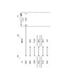
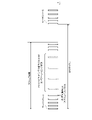
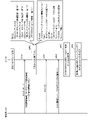
- FIG. 1 is a diagram showing the configuration of a mobile communication system according to an embodiment
- FIG. It is a figure which shows the structural example of the protocol stack based on embodiment.
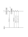
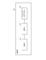
- FIG. 3 is a diagram showing an outline of wireless communication operation according to the embodiment;
- FIG. 2 is a diagram showing an overview of PDCCH skipping according to an embodiment;
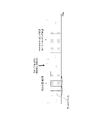
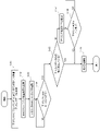
- FIG. 4 is a diagram showing an overview of search space set switching (SSSG switching) according to the embodiment;
- FIG. 4 is a diagram illustrating DRX and power saving states according to an embodiment; It is a figure which shows the structure of UE which concerns on embodiment. It is a figure which shows the structure of the base station which concerns on embodiment. It is a figure which shows the 1st example of operation
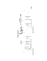
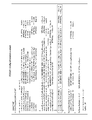
- FIG. 10 is a diagram showing a first configuration example of information elements included in an RRC message in the third operation example;
- FIG. 10 is a diagram showing a first configuration example of information elements included in an RRC message in the third operation example;
- FIG. 13 is a diagram showing a second configuration example of information elements included in the RRC message in the third operation example;
- FIG. 13 is a diagram showing a second configuration example of information elements included in the RRC message in the third operation example; It is a figure which shows the 4th example of operation
- FIG. 14 is a diagram showing a specific example 1 of operation using the switching timer according to the fourth operation example;
- FIG. 14 is a diagram showing a specific example 2 of operation using the switching timer according to the fourth operation example;
- DCI downlink control information
- one object of the present disclosure is to provide a communication device, a base station, and a communication method that enable flexible power saving using various search space sets.
- the mobile communication system 1 is, for example, a system conforming to 3GPP Technical Specifications (TS).
- TS 3GPP Technical Specifications
- a mobile communication system based on the 3GPP standard 5th Generation System (5GS), that is, NR (New Radio) will be described as an example.
- the mobile communication system 1 has a network 10 and user equipment (UE) 100 communicating with the network 10 .
- the network 10 includes an NG-RAN (Next Generation Radio Access Network) 20, which is a 5G radio access network, and a 5GC (5G Core Network) 30, which is a 5G core network.
- NG-RAN Next Generation Radio Access Network
- 5G Core Network 5G Core Network
- the UE 100 is a device used by a user.
- the UE 100 is, for example, a portable device such as a mobile phone terminal such as a smart phone, a tablet terminal, a notebook PC, a communication module, or a communication card.
- the UE 100 may be a vehicle (eg, car, train, etc.) or a device provided therein.
- the UE 100 may be a transport body other than a vehicle (for example, a ship, an airplane, etc.) or a device provided thereon.
- the UE 100 may be a sensor or a device attached thereto.
- the UE 100 includes a mobile station, a mobile terminal, a mobile device, a mobile unit, a subscriber station, a subscriber terminal, a subscriber device, a subscriber unit, a wireless station, a wireless terminal, a wireless device, a wireless unit, a remote station, and a remote terminal. , remote device, or remote unit.
- NG-RAN 20 includes multiple base stations 200 .
- Each base station 200 manages at least one cell.
- a cell constitutes the minimum unit of a communication area.
- One cell belongs to one frequency (carrier frequency) and is composed of one component carrier.
- the term “cell” may represent a radio communication resource and may also represent a communication target of UE 100 .
- Each base station 200 can perform radio communication with the UE 100 residing in its own cell.
- the base station 200 communicates with the UE 100 using the RAN protocol stack.
- Base station 200 provides NR user plane and control plane protocol termination towards UE 100 and is connected to 5GC 30 via NG interface.
- Such an NR base station 200 is sometimes referred to as a gNodeB (gNB).
- gNodeB gNodeB
- the 5GC 30 includes a core network device 300.
- the core network device 300 includes, for example, AMF (Access and Mobility Management Function) and/or UPF (User Plane Function).
- AMF Access and Mobility Management Function
- UPF User Plane Function
- AMF performs mobility management of UE100.
- UPF provides functions specialized for user plane processing.
- the AMF and UPF are connected with the base station 200 via the NG interface.
- the protocol of the radio section between the UE 100 and the base station 200 includes a physical (PHY) layer, a MAC (Medium Access Control) layer, an RLC (Radio Link Control) layer, a PDCP (Packet Data Convergence Protocol) layer, RRC layer.
- PHY physical
- MAC Medium Access Control
- RLC Radio Link Control
- PDCP Packet Data Convergence Protocol
- the PHY layer performs encoding/decoding, modulation/demodulation, antenna mapping/demapping, and resource mapping/demapping. Data and control information are transmitted between the PHY layer of the UE 100 and the PHY layer of the base station 200 via physical channels.
- the MAC layer performs data priority control, retransmission processing by hybrid ARQ (HARQ: Hybrid Automatic Repeat Request), random access procedures, and the like. Data and control information are transmitted between the MAC layer of the UE 100 and the MAC layer of the base station 200 via transport channels.
- the MAC layer of base station 200 includes a scheduler. The scheduler determines uplink and downlink transport formats (transport block size, modulation and coding scheme (MCS)) and allocation resources to the UE 100 .
- MCS modulation and coding scheme
- the RLC layer uses the functions of the MAC layer and PHY layer to transmit data to the RLC layer on the receiving side. Data and control information are transmitted between the RLC layer of the UE 100 and the RLC layer of the base station 200 via logical channels.
- the PDCP layer performs header compression/decompression and encryption/decryption.
- An SDAP (Service Data Adaptation Protocol) layer may be provided as an upper layer of the PDCP layer.
- the SDAP (Service Data Adaptation Protocol) layer performs mapping between an IP flow, which is the unit of QoS control performed by the core network, and a radio bearer, which is the unit of QoS control performed by the AS (Access Stratum).
- the RRC layer controls logical channels, transport channels and physical channels according to radio bearer establishment, re-establishment and release.
- RRC signaling for various settings is transmitted between the RRC layer of UE 100 and the RRC layer of base station 200 .
- UE 100 When there is an RRC connection between the RRC of UE 100 and the RRC of base station 200, UE 100 is in the RRC connected state. If there is no RRC connection between the RRC of the UE 100 and the RRC of the base station 200, the UE 100 is in RRC idle state. When the RRC connection between the RRC of UE 100 and the RRC of base station 200 is suspended, UE 100 is in RRC inactive state.
- the NAS layer located above the RRC layer performs session management and mobility management for UE100.
- NAS signaling is transmitted between the NAS layer of the UE 100 and the NAS layer of the core network device 300 (AMF).
- AMF core network device 300
- the UE 100 has an application layer and the like in addition to the radio interface protocol.
- a search space in this embodiment may be referred to as a search space set.
- the base station 200 configures the UE 100 with a search space corresponding to the candidate timing at which the PDCCH is provided.
- UE 100 in RRC connected state monitors PDCCH in the set search space, receives downlink control information (DCI) carried by PDCCH, and physical downlink according to resource allocation (scheduling) indicated by DCI. It receives a shared channel (PDSCH) and/or transmits a physical uplink shared channel (PUSCH). For example, the UE 100 may monitor a set of PDCCH candidates according to the corresponding search space.
- DCI downlink control information
- PUSCH physical uplink shared channel
- UE 100 monitors a set of PDCCH candidates in a control resource set (CORESET) in a downlink BWP (DL BWP: Downlink Bandwidth Part) in a serving cell in which PDCCH monitoring is set according to the corresponding search space.
- CORESET control resource set
- DL BWP Downlink Bandwidth Part
- monitoring may refer to decoding each of the PDCCH candidates according to the monitored DCI format.
- the base station 200 transmits an RRC message including PDCCH setting information (PDCCH setting information) to the UE 100, and performs various PDCCH settings for the UE 100.
- This RRC message is a UE-specific RRC message, and may be, for example, an RRC Reconfiguration message.
- the search space settings in the PDCCH settings include a search space period (also referred to as a PDCCH monitoring period), a search space offset (also referred to as a PDCCH monitoring offset), a search space duration (for example, the number of consecutive slots), and PDCCH monitoring. Including symbols, aggregation levels, search space types, and DCI formats.
- each search space (each set of search spaces) may be associated with one CORESET.
- the search space setting may be set for each of one or more DL BWPs.
- the search space type may include a UE-specific search space (USS: UE-specific search space) and/or a UE common search space (CSS: common search space).
- DCI formats include scheduling DCI formats used for PDSCH or PUSCH scheduling and non-scheduling DCI formats not used for such scheduling.
- DCI transmitted in a scheduling DCI format is called scheduling DCI
- DCI transmitted in a non-scheduling DCI format is called non-scheduling DCI.
- Scheduling DCI formats include a downlink DCI format used for PDSCH scheduling (eg, DCI format 1_0, DCI format 1_1, DCI format 1_2) and an uplink DCI format used for PUSCH scheduling (eg, DCI format 0_0, DCI format 0_1 and DCI format 0_2).
- the scheduling DCI may be UE-specific DCI that is sent for each UE. For example, the scheduling DCI may be transmitted applying the RNTI assigned to each UE.
- non-scheduling DCI formats include, for example, DCI format 2_0 and DCI format 2_6.
- the non-scheduling DCI may be a DCI that can be transmitted to multiple UEs 100 at once.
- non-scheduling DCI may be transmitted by applying a common RNTI to multiple UEs 100 .
- step S2 the UE 100 starts monitoring the PDCCH in the search space set by the base station 200.
- DCI format 1_0, DCI format 0_0, DCI format 1_1, DCI format 0_1, DCI format 1_2, and DCI format 0_2 are configured in the UE 100, and the UE 100 monitors the PDCCH (DCI) based on the configuration.
- base station 200 may configure UE 100 to monitor DCI format 1_0 and DCI format 0_0 in a certain search space.
- base station 200 may configure UE 100 to monitor DCI format 1_1 and DCI format 0_1 in a certain search space.
- base station 200 may configure UE 100 to monitor DCI format 1_2 and DCI format 0_2 in a certain search space. That is, for example, base station 200 may configure UE 100 to monitor PDCCH candidates for DCI format 1_0 and DCI format 0_0 when CSS is configured for a certain search space. Also, base station 200 may configure UE 100 to monitor PDCCH candidates for DCI format 2_0 when CSS is configured for a certain search space. In addition, base station 200 instructs UE 100 to monitor PDCCH candidates for DCI format 1_0 and DCI format 0_0 or DCI format 1_1 and DCI format 0_1 when USS is configured for a certain search space.
- base station 200 instructs UE 100 to monitor PDCCH candidates for DCI format 1_0 and DCI format 0_0 or DCI format 1_2 and DCI format 0_2 when USS is configured for a certain search space. can be set to
- the UE 100 receives and detects DCI addressed to itself from the base station 200.
- the UE 100 receives C-RNTI (Cell-Radio Network Temporary Identifier), MCS-C-RNTI (Modulation and Coding Scheme-C-RNTI), or CS-RNTI (Configured Scheduling- RNTI) is used to blind-decode the PDCCH, and the successfully decoded DCI is acquired as the DCI addressed to the own UE.
- the DCI transmitted from the base station 200 is added with CRC parity bits scrambled by C-RNTI, MCS-C-RNTI, or CS-RNTI.
- step S4 the UE 100 receives downlink data from the base station 200 on the scheduled PDSCH.
- step S5 the UE 100 transmits uplink data to the base station 200 on the scheduled PUSCH.
- the UE 100 monitors the PDCCH provided at predetermined intervals in the search space based on the search space setting set by the base station 200 .
- a PDCCH monitoring state is an example of a first state.
- base station 200 transmits to UE 100 a skip instruction DCI that instructs PDCCH skipping.
- Skip instruction DCI is an example of switching instruction DCI.
- a skip indication DCI is a scheduling DCI or a non-scheduling DCI, but in this embodiment, it is mainly assumed that a scheduling DCI is used as a skip indication DCI.
- the UE 100 skips PDCCH monitoring for a predetermined period in response to receiving the skip instruction DCI from the base station 200 .
- a PDCCH skipping state is an example of a second state (power saving state).
- the predetermined period for skipping PDCCH monitoring may be set by higher layer signaling (RRC message).
- the predetermined period may be determined by a timer value (that is, a setting value of a switching timer), or may be determined by the number of consecutive slots or the number of consecutive search spaces.
- the base station 200 configures multiple search space sets, which are sets of settings related to search spaces, in the UE 100 through higher layer signaling (RRC messages).
- a set of search space-related settings is called a search space set (SSS) or a search space set group (SSSG), but in the following it will be mainly called SSSG.
- One SSSG includes one or more search space settings and is identified by an SSSG index.
- base station 200 has SSSG#0 (first search space set) in which search spaces are provided with a predetermined period, and SSSG#1 (second search space set) in which search spaces are provided with a period longer than the predetermined period. shall be set in the UE 100.
- the base station 200 sets two SSSGs, SSSG#0 and SSSG#1, to the UE 100.
- Three or more SSSGs are set for each of one or more BWPs (for example, DL BWP). You may set to UE100.
- setting a plurality of BWPs (or three or more SSSGs) in the UE 100 may mean setting a plurality of SSSGs (or three or more SSSGs) for one BWP, or a plurality of may mean setting multiple SSSGs (or three or more SSSGs) for each BWP.
- the UE 100 monitors the PDCCH provided at predetermined intervals in the search space based on SSSG#0.
- a state in which such SSSG#0 is applied is an example of a first state.
- the base station 200 transmits to the UE 100 a switching instruction DCI that instructs SSSG switching.
- the skip indication DCI is scheduling DCI or non-scheduling DCI, but in this embodiment, it is mainly assumed that scheduling DCI is used as switching indication DCI. That is, the base station 200 uses the scheduling DCI to instruct the UE 100 to switch from SSSG#0 to SSSG#1.
- the UE 100 starts switching to SSSG#1 in response to receiving the switching instruction DCI.
- UE 100 performs switching to SSSG#1 in a symbol after a switching delay time (Switch delay) from the last symbol of PDCCH in SSSG#0.
- Switch delay is set from the base station 200 to the UE 100 by higher layer signaling (RRC message).
- UE 100 monitors PDCCHs provided in a cycle longer than a predetermined cycle in search spaces.
- a state in which such SSSG#1 is applied is an example of a second state (power saving state).
- Such search space set switching reduces the power consumption required for the UE 100 to monitor the PDCCH, enabling dynamic power saving.
- switching from SSSG#1 to SSSG#0 may be instructed by the base station 200 using DCI in the same manner as switching from SSSG#0 to SSSG#1, or the UE 100 may switch from SSSG#1 using a timer. You may switch to SSSG#0.
- the timer value of such a switching timer (Switching timer) is set from the base station 200 to the UE 100 by higher layer signaling (RRC message).
- the UE 100 starts monitoring the PDCCH in SSSG#1 in response to detection of the switching instruction DCI to SSSG#1, sets the value of the switching timer to the value set by the upper layer, and activates the switching timer.
- UE 100 decrements the value of the switching timer, stops monitoring PDCCH in SSSG#1 when the switching timer expires, and starts monitoring PDCCH in SSSG#0 after a switch delay.
- "#0" in SSSG#0 and "#1" in SSSG#1 indicate an index (also called a search space group ID) for a set (group) of search spaces. That is, one or more search space sets may be associated with a set (group) of search spaces identified by an index.
- base station 200 may configure a set (group) of search spaces for UE 100 by configuring an index associated with the one or more search space sets.
- the name SSSG is merely an example, and any name may be used as long as it is a search space set (group) associated with one or more search space sets.
- one SSSG set in the UE 100 is set to have no search space, and switching to the one SSSG is indicated by DCI, thereby realizing the same operation as the PDCCH skipping described above. Also, in other SSSGs set in the UE 100, it is possible to set them to have a long search space cycle, and to instruct switching to the one SSSG by DCI. In order to realize such an operation, it is necessary to set a total of three SSSGs, SSSG having a normal search space period, SSSG having no search space, and SSSG having a long search space period, in the UE 100. .
- FIG. Flexible power saving can be realized by setting such various SSSGs in the UE 100 and instructing switching of SSSGs by DCI.
- the UE 100 discontinuously monitors the PDCCH using the DRX operation.
- the DRX operation is controlled by the following DRX parameters.
- - DRX cycle Defines the cycle in which the UE 100 wakes up.
- On duration On-duration: This is the period during which the UE 100 waits to receive the PDCCH after waking up. If the UE 100 successfully decodes the PDCCH, the UE 100 remains awake and starts an inactivity-timer.
- Inactivity timer Defines the time period during which the UE 100 waits after the last successful PDCCH decoding and sleeps again when the PDCCH decoding fails.
- Retransmission timer defines the time interval during which retransmissions are expected.
- the UE 100 configured with DRX does not need to monitor the PDCCH in the sleep state (that is, the reception off period), so the power consumption of the UE 100 can be reduced.
- the UE 100 waits to receive the PDCCH and monitors the PDCCH in the search space during the active time.
- the active time is any of the on duration timer (drx-onDurationTimer), the inactivity timer (drx-InactivityTimer), the downlink retransmission timer (drx-RetransmissionTimerDL), and the uplink retransmission timer (drx-RetransmissionTimerUL) is in operation. It's time.
- Downlink retransmission timer (drx-RetransmissionTimerDL) and uplink retransmission timer (drx-RetransmissionTimerUL) are examples of retransmission related timers for DRX operation in RRC connected state.
- the scheduling DCI is used as the switching instruction DCI that instructs switching to the power saving state
- data transmission/reception may occur between the base station 200 and the UE 100, and data retransmission processing by HARQ may be required. Therefore, if the UE 100 immediately starts switching to the power saving state in response to receiving the scheduling DCI instructing switching to the power saving state, there is a concern that the HARQ process cannot be performed appropriately.
- UE 100 in the RRC connected state performs sounding reference signal (SRS) transmission to base station 200 , channel state information (CSI) measurement, and CSI reporting to base station 200 .
- SRS sounding reference signal
- CSI channel state information
- the period in which the UE 100 is in the power saving state is considered to be a period in which data transmission/reception is temporarily not performed, so it is possible to reduce the power consumption required for SRS transmission, CSI measurement, and CSI reporting. desirable.
- UE 100 includes communication unit 110 and control unit 120 .
- the communication unit 110 performs wireless communication with the base station 200 by transmitting and receiving wireless signals to and from the base station 200 .
- the communication unit 110 has at least one receiver and at least one transmitter.
- Receivers and transmitters may comprise antennas and RF circuits.
- the antenna converts a signal into radio waves and radiates the radio waves into space. Also, the antenna receives radio waves in space and converts the radio waves into signals.
- the RF circuitry performs analog processing of signals transmitted and received through the antenna.
- the RF circuitry may include high frequency filters, amplifiers, modulators, low pass filters, and the like.
- the control unit 120 performs various controls in the UE 100.
- Control unit 120 controls communication with base station 200 via communication unit 110 .
- the operations of the UE 100 described above and below may be operations under the control of the control unit 120 .
- the control unit 120 may include at least one processor capable of executing a program and a memory that stores the program.
- the processor may execute a program to operate the control unit 120 .
- the control unit 120 may include a digital signal processor that performs digital processing of signals transmitted and received through the antenna and RF circuitry.
- the digital processing includes processing of the protocol stack of the RAN. Note that the memory stores programs executed by the processor, parameters related to the programs, and data related to the programs.
- the memory may include at least one of ROM (Read Only Memory), EPROM (Erasable Programmable Read Only Memory), EEPROM (Electrically Erasable Programmable Read Only Memory), RAM (Random Access Memory), and flash memory. All or part of the memory may be included within the processor.
- the communication unit 110 in the first state in which the PDCCH is monitored in the search space, bases the scheduling DCI indicating the radio resources (specifically, PDSCH resources, PUSCH resources) allocated to the UE 100. Receive on PDCCH from station 200 .
- the control unit 120 controls the communication unit 110 to receive or transmit data using the radio resource based on the scheduling DCI.
- control section 120 performs HARQ processing on the data.
- the attached retransmission-related timer is pending to initiate switching while it is running. As a result, even when scheduling DCI is used as an instruction to switch to the power saving state, HARQ processing can be performed appropriately. Details of such an operation will be described in a first operation example described later.
- control section 120 performs at least one operation among SRS transmission to base station 200, CSI measurement, and CSI reporting to base station 200 in the first state in which PDCCH is monitored in the search space.
- a predetermined control is performed to control the Communication section 110 receives a switching instruction DCI from base station 200 on the PDCCH, which instructs switching to a second state (for example, power saving state) in which search space settings are different from the first state.
- Control section 120 performs control different from predetermined control for at least one operation of SRS transmission, CSI measurement, and CSI reporting in response to reception of the switching instruction DCI. This makes it possible to apply control optimized for the power saving state in SRS transmission, CSI measurement and CSI reporting. Therefore, further reduction in power consumption can be realized while reducing the power consumption necessary for monitoring the PDCCH. Details of such an operation will be described in a second operation example described later.
- the first state may be a state in which the first SSSG among multiple SSSGs set in the UE 100 by the base station 200 is applied.
- the second state may be a state in which a second SSSG different from the first SSSG among the plurality of SSSGs is applied.
- the communication unit 110 may receive a scheduling DCI that instructs switching from the first SSSG to the second SSSG as a switching instruction.
- the first state may be a state in which the PDCCH provided at predetermined intervals is monitored in the search space.
- the second state may be a state in which PDCCH is monitored in a search space provided in a period longer than a predetermined period, or a state in which PDCCH monitoring is skipped.
- the second state may be realized by the second SSSG described above.
- the communication unit 110 is set in the information field in the switching instruction DCI for instructing switching of the SSSG applied by the UE 100 and the index of each of one or more SSSGs set in the UE 100.
- the one or more SSSGs include at least one of an SSSG that periodically monitors the PDCCH and an SSSG that skips the monitoring of the PDCCH.
- the control unit 120 uses SSSG having an index corresponding to the value set in the information field in the received switching instruction DCI based on the correspondence information. control PDCCH monitoring.
- one information field provided in the switching instruction DCI can specify one of a plurality of search space sets with different search space cycles or specify a search space set that does not monitor the PDCCH. Even if various search space sets are used, an increase in DCI size can be suppressed. Details of such an operation will be described in a third operation example described later.
- the communication unit 110 receives from the base station 200 a switching instruction DCI that instructs switching to one SSSG among three or more SSSGs set in the UE 100 .
- the control unit 120 may start a timer that determines the duration for which PDCCH monitoring or PDCCH monitoring skipping in the one SSSG is applied.
- the UE 100 switches to the default SSSG set by the base station 200 among three or more SSSGs. This makes it possible to realize flexible power saving using various search space sets.
- the base station 200 can grasp the SSSG to switch to. It enables timer-based switching for different SSSGs. Details of such an operation will be described in a fourth operation example described later.
- Base station 200 has communication unit 210 , network interface 220 , and control unit 230 .
- the communication unit 210 receives radio signals from the UE 100 and transmits radio signals to the UE 100.
- the communication unit 210 may comprise one or more receivers for receiving radio signals and one or more transmitters for transmitting radio signals.
- the network interface 220 transmits and receives signals to and from the network.
- the network interface 220 receives signals from adjacent base stations connected via an Xn interface, which is an interface between base stations, and transmits signals to adjacent base stations. Also, the network interface 220 receives signals from the core network device 300 connected via the NG interface, for example, and transmits signals to the core network device 300 .
- the control unit 230 performs various controls in the base station 200.
- the control unit 230 controls communication with the UE 100 via the communication unit 210, for example.
- the control unit 230 controls communication with nodes (for example, adjacent base stations, core network device 300) via the network interface 220, for example.
- the operations of the base station 200 described above and below may be operations under the control of the control unit 230 .
- the control unit 230 may include at least one processor capable of executing programs and a memory storing the programs.
- the processor may execute a program to operate the controller 230 .
- Control unit 230 may include a digital signal processor that performs digital processing of signals transmitted and received through the antenna and RF circuitry.
- the digital processing includes processing of the protocol stack of the RAN.
- the memory stores programs executed by the processor, parameters related to the programs, and data related to the programs. All or part of the memory may be included within the processor.
- the base station 200 performs radio communication with the UE 100 that monitors the PDCCH in the search space.
- the communication unit 210 indicates the correspondence between the index of each of one or more SSSGs set in the UE 100 and the value set in the information field in the switching instruction DCI that instructs switching of the SSSG to be applied in the UE 100. Relevant information is transmitted to UE100.
- the one or more SSSGs include at least one of an SSSG that periodically monitors the PDCCH and an SSSG that skips the monitoring of the PDCCH.
- the communication unit 210 transmits to the UE 100 a switching instruction DCI that instructs switching to one SSSG among three or more SSSGs set in the UE 100 .
- the control unit 230 may set the default SSSG to be switched to in the UE 100 when a timer that determines the duration of PDCCH monitoring or PDCCH monitoring skipping in the one SSSG expires.
- HARQ processing which is data retransmission processing by HARQ
- UE 100 may be required. Therefore, when UE 100 immediately starts switching to the power saving state, HARQ processing is performed appropriately. I have concerns that I can't. Therefore, the UE 100 (control unit 120) suspends the start of switching instructed by the switching instruction DCI (scheduling DCI) while the retransmission-related timer associated with the HARQ process for the data scheduled by the switching instruction DCI (scheduling DCI) is in operation. do.
- the UE 100 receives the scheduling DCI as the switching instruction DCI from the base station 200 on the PDCCH.
- a scheduling DCI may include an information field indicating a switching destination SSSG in addition to an information field indicating the PDSCH resource or PUSCH resource allocated to UE 100 .
- the UE 100 receives or transmits data scheduled by the scheduling DCI. For example, the UE 100 (communication unit 110) receives downlink data using the assigned PDSCH resources, and transmits uplink data using the assigned PUSCH resources.
- the UE 100 receives downlink data
- the UE 100 controls unit 120) attempts data decoding of the received downlink data, and HARQ feedback indicating whether data decoding is successful, that is, ACK Or NACK is fed back to the base station 200 .
- UE 100 (communication unit 110) transmits uplink data UE 100 (control unit 120) sends HARQ feedback indicating whether base station 200 has successfully decoded uplink data, that is, ACK or NACK. Receive from base station 200 .
- UE 100 (control unit 120) manages HARQ processing for each data to be received or transmitted using a timer, and continues HARQ processing until data decoding of the data is completed.
- step S13 the UE 100 (control unit 120) determines whether any of the next retransmission-related timers used for HARQ processing is in operation.
- ⁇ Downlink HARQ RTT timer (drx-HARQ-RTT-TimerDL) This timer is used for HARQ processing of downlink data, and defines the minimum period until downlink allocation for HARQ retransmission expected by the MAC entity of UE 100 .
- the UE 100 (control unit 120) activates the downlink HARQ RTT timer in response to transmission of HARQ feedback for downlink data.
- the UE 100 (control unit 120) does not need to monitor the PDCCH while the downlink HARQ RTT timer is operating.
- drx-RetransmissionTimerDL Downlink retransmission timer
- This timer is used for HARQ processing of downlink data and defines the maximum period until downlink retransmission is received.
- the UE 100 (control unit 120) activates the downlink retransmission timer.
- the UE 100 (control unit 120) monitors the PDCCH and waits for retransmission data while the downlink retransmission timer is operating.
- drx-HARQ-RTT-TimerUL This timer is used for HARQ processing of uplink data, and defines the minimum period until the MAC entity of UE 100 receives the HARQ retransmission grant.
- the UE 100 (control unit 120) activates the downlink retransmission timer according to transmission of uplink data.
- the UE 100 (control unit 120) does not need to monitor the PDCCH while the uplink HARQ RTT timer is operating.
- the UE 100 (control unit 120) activates the uplink retransmission timer when the uplink HARQ RTT timer expires.
- the UE 100 (control section 120) monitors the PDCCH while the uplink retransmission timer is operating.
- step S14 the UE 100 (control unit 120) suspends the start of switching indicated by the switching instruction DCI received in step S11. do.
- step S15 the UE 100 (control unit 120) starts switching instructed by the switching instruction DCI received in step S11 or Run.
- the UE 100 (control unit 120) may perform SSSG switching from the first slot after the retransmission-related timer expires.
- the period during which the retransmission-related timer is operating constitutes at least part of the switching delay time (Switch delay) for switching indicated by the switching instruction DCI.
- switch delay switching delay time
- UE 100 control section 120
- the start of switching instructed by the switching instruction DCI may be suspended.
- the switching delay time may also include periods during which retransmission-related timers such as: The period during which the drx-HARQ-RTT-TimerDL is running for the corresponding HARQ process triggered in the first symbol after the end of the DL HARQ feedback transmission: A period during which the drx-RetransmissionTimerDL is running, initiated if the corresponding HARQ process of the first symbol after the expiry of the drx-HARQ-RTT-TimerDL was not successfully decoded: A period during which the drx-HARQ-RTT-TimerUL is running for the corresponding HARQ process, started on the first symbol after the end of the first transmission (within the bundle) of the corresponding PUSCH transmission: • The period during which the drx-RetransmissionTimerUL is running, started for the corresponding HARQ process on the first symbol after the drx-HARQ-RTT-TimerUL expires.
- retransmission-related timers such as:
- the UE 100 when the UE 100 (control unit 120) is executing a plurality of HARQ processes, if even one retransmission-related timer of the plurality of HARQ processes is operating, switching instructed by the switching instruction DCI is started. may be retained. For example, the UE 100 is based on the expiration of drx-RetransmissionTimerDL corresponding to all HARQ processes and/or expiration of drx-RetransmissionTimerUL corresponding to all HARQ processes (for example, the first slot after expiration ) may perform SSSG switching.
- the UE 100 uses a configured DL assignment (that is, a downlink DCI format having a CRC scrambled with CS-RNTI) and/or a configured UL grant (that is, a CRC scrambled with CS-RNTI ) is received, the above actions may be performed.
- a configured DL assignment that is, a downlink DCI format having a CRC scrambled with CS-RNTI
- a configured UL grant that is, a CRC scrambled with CS-RNTI
- various existing timers for DRX are used, but not limited to this, they are used for HARQ processing/retransmission processing for PDCCH skipping and/or SSSG switching set in higher layers.
- a timer may be used.
- Such timers are, for example, DCIbasedPowerSaving-HARQ-RTT-TimerDL, DCIbasedPowerSaving-HARQ-RTT-TimerUL, DCIbasedPowerSaving-RetransmissionTimerDL, DCIbasedPowerSaving-RetransmissionTimerUL, etc.
- DCIbasedPowerSaving-HARQ-RTT-TimerDL is an example of a downlink HARQ RTT timer
- DCIbasedPowerSaving-HARQ-RTT-TimerUL is an example of an uplink HARQ RTT timer
- DCIbasedPowerSaving-RetransmissionTimerDL is an example of a downlink retransmission timer.
- DCIbasedPowerSaving-RetransmissionTimerUL is an example of an uplink retransmission timer.
- step S101 the UE 100 (communication unit 110) receives the downlink scheduling DCI as the switching instruction DCI on the PDCCH.
- a downlink scheduling DCI is a DCI that allocates radio resources (that is, PDSCH resources) for downlink data.
- the UE 100 (communication unit 110) receives downlink data from the base station 200 using PDSCH resources allocated by the downlink scheduling DCI.
- UE 100 (control unit 120) attempts to decode the received downlink data.
- step S102 the UE 100 (communication unit 110) transmits to the base station 200 HARQ feedback indicating whether or not the downlink data received in step S102 has been successfully decoded.
- step S103 the UE 100 (control unit 120) activates the downlink HARQ RTT timer in response to transmission of HARQ feedback corresponding to downlink data.
- the UE 100 (control unit 120) suspends the start of switching indicated by the switching instruction DCI while the downlink HARQ RTT timer is operating.
- step S105 the UE 100 (control unit 120) determines whether the downlink data has been successfully decoded. If the downlink data has been successfully decoded (step S105: YES), in step S106, the UE 100 (control unit 120) starts switching instructed by the switching instruction DCI.
- step S107 the UE 100 (control unit 120) activates the downlink retransmission timer in response to the expiration of the downlink HARQ RTT timer. do.
- the UE 100 (control unit 120) monitors the PDCCH while the downlink retransmission timer is operating, and suspends the start of switching indicated by the switching instruction DCI.
- step S106 the UE 100 (control unit 120) starts switching instructed by the switching instruction DCI. If retransmission data is received from the base station 200 while the downlink retransmission timer is operating, the UE 100 (control unit 120) may stop the downlink retransmission timer and return to step S102.
- the UE 100 receives the uplink scheduling DCI as the switching instruction DCI on the PDCCH.
- the uplink scheduling DCI is a DCI that allocates radio resources (that is, PUSCH resources) for uplink data.
- step S202 the UE 100 (communication unit 110) transmits uplink data to the base station 200 using PUSCH resources allocated by the uplink scheduling DCI.
- step S203 the UE 100 (control unit 120) activates the uplink HARQ RTT timer in response to transmission of uplink data.
- the UE 100 (control unit 120) suspends the start of switching indicated by the switching instruction DCI while the uplink HARQ RTT timer is operating.
- step S204 When the uplink HARQ RTT timer expires (step S204: YES), the UE 100 (control unit 120) activates the uplink retransmission timer in step S205.
- the UE 100 (control unit 120) monitors the PDCCH while the uplink retransmission timer is operating, and suspends the start of switching indicated by the switching instruction DCI.
- step S207 the UE 100 (control unit 120) starts switching instructed by the switching instruction DCI.
- the UE 100 that has received the scheduling DCI as a switching instruction has a retransmission-related timer associated with HARQ processing for data scheduled by the scheduling DCI running. , suspends the start of switching. By this means, even when scheduling DCI is used as a switching instruction, it is possible to appropriately perform HARQ processing.
- CSI reporting to the base station 200 may be considered.
- the UE 100 that has received the switching instruction DCI is instructed by the scheduling DCI to report the aperiodic CSI to the base station 200
- the UE 100 (control section 120) sends the CSI report to the base station 200 in the scheduled PUSCH.
- the start of switching indicated by the switching instruction DCI may be put on hold.
- the UE 100 (control unit 120) may start switching indicated by the switching instruction DCI in response to transmitting the CSI report on the scheduled PUSCH.
- the details of the CSI report will be explained in a second operation example described later.
- the period in which the UE 100 is in the power saving state is considered to be a period in which data transmission and reception are not temporarily performed, so the power consumption required for SRS transmission, CSI measurement, and CSI reporting is also reduced. is desirable.
- SRS transmission refers to an operation in which the base station 200 transmits to the base station 200 an SRS, which is an uplink physical signal for channel estimation used for estimating the uplink channel state.
- SRS transmission is performed according to the setting of .
- SRS reporting is an operation for uplink link adaptation.
- Link adaptation adapts the modulation and coding scheme (MCS) applied to data transmission to channel conditions. During the period in which the UE 100 is in the power saving state, SRS transmission is suppressed because there is little need to perform uplink link adaptation.
- MCS modulation and coding scheme
- CSI measurement refers to the operation of measuring a reference signal used for estimating the downlink channel state, and the UE 100 performs CSI measurement according to the settings from the base station 200 .
- the UE 100 uses at least a channel state information reference signal (CSI-RS) and a synchronization signal/physical broadcast channel (SS/PBCH) block transmitted by the base station 200 CSI measurements based on one are made.
- CSI reporting refers to an operation of transmitting to base station 200 a CSI report indicating a channel state estimated according to the result of CSI measurement, and UE 100 reports CSI according to settings from base station 200 .
- CSI-RS channel state information reference signal
- SS/PBCH synchronization signal/physical broadcast channel
- the channel state includes a channel quality indicator (CQI), a rank indicator (RI), a precoding matrix indicator (PMI), an SS/PBCH block resource indicator (SS/PBCH block resource indicator: SSBRI), CSI-RS resource indicator (CSI-RS resource indicator: CRI), layer indicator (layer indicator: LI), and layer 1 reference signal received power (Layer 1 reference signal received power: L1-RSRP) including one or more of CSI reporting may be done on PUCCH or PUSCH.
- CSI measurement and CSI reporting are operations for downlink link adaptation. During the period in which the UE 100 is in the power saving state, the need to perform downlink link adaptation is low, so CSI measurement and CSI reporting are suppressed.
- UE 100 transmits SRS to base station 200, measures CSI, and reports CSI to base station 200 in the first state in which PDCCH is monitored in the search space.
- Predetermined control is performed to control the operation of at least one of In the first state, UE 100 (control unit 120) may periodically perform at least one of SRS transmission, CSI measurement, and CSI reporting.
- the UE 100 (control unit 120) performs at least one of periodic SRS transmission and periodic CSI reporting in the first state.
- Periodic SRS transmissions may include semi-persistent SRS transmissions.
- Periodic CSI reporting may include semi-persistent CSI reporting on PUCCH or PUSCH.
- the UE 100 receives, on the PDCCH, a switching instruction DCI that instructs switching to a second state (for example, power saving state) in which the search space settings are different from the first state.
- the switching instruction DCI is not limited to the scheduling DCI as described above, and may be a non-scheduling DCI.
- the switching indication DCI may include an information field indicating the switching destination SSSG.
- step S303 the UE 100 (control unit 120) performs control different from the predetermined control for at least one operation among SRS transmission, CSI measurement, and CSI reporting in response to receiving the switching instruction DCI.
- the UE 100 stops at least one of SRS transmission, CSI measurement, and CSI reporting within the switching delay time (Switch delay) from the first state to the second state.
- the UE 100 may stop periodic SRS transmission and periodic CSI reporting within the switching delay time.
- Such control is such that "within the switching delay time composed of Pswitch symbols, the UE - Periodic SRS transmission and semi-persistent SRS transmission - Semi-persistent CSI configured on PUSCH Periodic CSI reporting that is L1-RSRP on PUCCH if ps-TransmitPeriodicL1-RSRP is not configured with value true L1 on PUCCH if ps-TransmitOtherPeriodicCSI is not configured with value true - not expected to perform periodic CSI reporting that is not RSRP'.
- the first state is a state in which the PDCCH provided at predetermined intervals is monitored in the search space
- the second state is a state in which the monitoring of the PDCCH is skipped (PDCCH skipping state).
- Good see Figure 4).
- UE 100 does not have to perform at least one of SRS transmission, CSI measurement, and CSI reporting in the second state.
- the first state is a state in which PDCCH provided in a predetermined cycle is monitored in search spaces
- the second state is a state in which PDCCH is monitored in search spaces provided in a cycle longer than the predetermined cycle. It may be in a state where it does (see FIG. 5). Switching from the first state to the second state may be realized by SSSG switching.
- UE 100 (control section 120) may perform at least one operation of SRS transmission, CSI measurement, and CSI reporting only in the search space time interval.
- the UE 100 may perform aperiodic SRS transmission only in the monitor slot, which is the time interval of the search space.
- a control is such that "a UE for which SSSG switching is set by higher layer signaling triggers aperiodic SRS transmission when the search space period is longer than a predetermined value (e.g., 80 milliseconds). , do not expect SRS resources to be available outside of the corresponding monitor slot'.
- UE 100 may perform CSI measurement only in the monitor slot, which is the time interval of the search space.
- Such control is expressed as "a UE configured for SSSG switching by higher layer signaling excludes slots other than the monitor slot corresponding to the search space for the most recent CSI measurement occasions for CSI reporting".
- ⁇ UE for which SSSG switching is set by higher layer signaling if the period of the search space is longer than a predetermined value (for example, 80 ms), the CSI-RS resource is used other than the corresponding monitor slot. It may be expressed as "I do not expect it to be possible”.
- the UE 100 that has received the switching instruction DCI performs at least one operation among SRS transmission, CSI measurement, and CSI reporting in response to reception of the switching instruction DCI. , different control from the control before receiving the switching instruction DCI is performed.
- This makes it possible to apply control optimized for the power saving state, for example, control optimized for the extended search space period, in SRS transmission, CSI measurement, and CSI reporting. Further reduction in power consumption can be realized while reducing the power consumption.
- power saving is performed by switching SSSG.
- a plurality of SSSGs having different search space periods and from among various SSSGs including SSSGs having no search space, one or more SSSGs can be set in the UE 100, and switching of SSSGs is performed by DCI.
- Flexible power saving is realized by instructing with
- the base station 200 transmits one or more RRC messages to the UE100.
- the one or more RRC messages may include a dedicated RRC message (eg, RRCReconfiguration message) sent for each UE.
- UE 100 receives the RRC message.
- the RRC message is set in the index of each of one or more SSSGs set in the UE 100 and the information field in the switching instruction DCI that instructs switching of the SSSG applied by the UE 100 (hereinafter referred to as "SSSG information field"). It contains correspondence information that indicates the correspondence with the value to be specified.
- the one or more SSSGs include at least one of an SSSG that periodically monitors the PDCCH and an SSSG that skips the monitoring of the PDCCH.
- the correspondence information includes "SSSG index #0: value "00””, “SSSG index #1: value “01””, “SSSG index #2: value “10”. ””, and “SSSG index #3: value “11””.
- the base station 200 is not limited to collectively setting these four SSSGs in the UE 100 , and may set four SSSGs in the UE 100 by dividing the two SSSGs into two times, for example.
- the value set in the SSSG information field may be configured in bitmap format.
- bit position (code point) that is "1” may be associated with the SSSG index.
- the RRC message further includes search space configuration information associated with each SSSG index.
- Search space setting information includes one or more search space settings.
- Each search space configuration includes search space period, search space offset, search space duration (eg, number of consecutive slots), symbols for PDCCH monitoring, aggregation level, search space type, DCI format, and so on.
- the search space setting information associated with SSSG index #0 is information for setting the first search space cycle as the search space cycle.
- the search space setting information associated with SSSG index #1 is information for setting the second search space cycle as the search space cycle.
- the search space setting information associated with SSSG index #2 is information for setting the third search space cycle as the search space cycle.
- Search space setting information associated with SSSG index #3 is information indicating that no search space is set. That is, SSSG index #3 is associated with search space configuration information indicating PDCCH skipping.
- the RRC message may contain field setting information indicating the presence or absence of the SSSG information field for each of one or more DCI formats.
- the switching instruction DCI is a DCI having a DCI format in which the field setting information indicates that there is an SSSG information field.
- the presence or absence of the SSSG information field (presence/absence) may be set commonly or independently for the non-scheduling DCI and/or the scheduling DCI. Presence/absence of the SSSG information field may be set commonly for DCI format 1_1 and DCI format 0_1, and commonly for DCI format 1_2 and DCI format 0_2.
- the RRC message may contain bit number setting information indicating the number of bits in the SSSG information field for each of one or more DCI formats.
- the number of bits in the SSSG information field may be set directly for non-scheduling DCI and/or scheduling DCI, commonly or independently.
- the number of bits of the SSSG information field may be set commonly for DCI format 1_1 and DCI format 0_1 and/or commonly for DCI format 1_2 and DCI format 0_2. For example, even if up to 2-bit SSSG information field is set for DCI format 1_1 and/or DCI format 0_1 and/or 1-bit SSSG information field is set for DCI format 1_2 and DCI format 0_2, good.
- the RRC message may include a timer setting value of a switching timer for each of one or more SSSGs. Details of such a switching timer will be described in a fourth operation example described later.
- step S402 the UE 100 (control unit 120) stores the information set by the base station 200.
- the base station 200 transmits to the UE 100 a MAC CE that designates activation or deactivation of SSSG for each SSSG index (hereinafter referred to as "SSSG state selection MAC CE"). good too.
- UE 100 receives the SSSG state selection MAC CE.
- the SSSG state selection MAC CE directs activation/deactivation for each SSSG index.
- the activated SSSG will be in a valid state as a switch-to SSSG, and the deactivated SSSG will be in an invalid state as a switch-to SSSG.
- deactivation may be prohibited for the default SSSG.
- the default SSSG will be explained in the fourth operation example below.
- an SSSG state selection MAC CE is identified by a MAC subheader with an LCID defined for the SSSG state selection MAC CE.
- the SSSG state selection MAC CE may include a "cell ID field” indicating the serving cell to which the SSSG state selection MAC CE is applied.
- the SSSG state selection MAC CE may include a "Ti field” indicating activation/deactivation for each entry "i" of the SSSG index list consisting of SSSG indices.
- the 'Ti field' includes the 'T0 field' through the 'T(n-1) field' and is set to the value '1' for the SSSG to be activated.
- 'n' denotes the maximum number of SSSGs that can be activated, for example '4'.
- "T0 field” is set to "1” and " The "T1 field” is set to "0", the "T2 field” to "1", and the "T3 field” to "1".
- the SSSG information field may be configured in bitmap format intended only for activated SSSGs. For example, the first valid SSSG is mapped to codepoint 1 in the SSSG information field, the second valid SSSG is mapped to codepoint 2 in the SSSG information field. Assuming that SSSG index #0 is activated, SSSG index #1 is deactivated, SSSG index #2 is activated, and SSSG index #3 is deactivated, the number of bits in the SSSG information field is "2". Yes, "10" indicates SSSG index #0 and "01" indicates SSSG index #2.
- the base station 200 (communication unit 210) transmits a switching instruction DCI having an SSSG information field to the UE 100 on the PDCCH.
- UE 100 (communication section 110) receives the switching instruction DCI on the PDCCH.
- the UE 100 (control unit 120) may determine whether the DCI format of the detected DCI corresponds to the switching instruction DCI based on the field setting information set by the base station 200.
- step S405 the UE 100 (control unit 120) acquires the value set in the SSSG information field of the switching instruction DCI received in step S404.
- the UE 100 (control unit 120) may specify the number of bits in the SSSG information field based on the number-of-bits setting information set by the base station 200, and then acquire the value set in the SSSG information field.
- the UE 100 (control unit 120) identifies the number of bits in the SSSG information field based on the number of SSSG indexes set in the UE 100 (that is, the number of entries in the set SSSG index list), and the SSSG information field You can get the value set to .
- the UE 100 calculates the number of bits of the SSSG information field by an integer value rounded up after the decimal point of log2 (I) and may be specified.
- step S406 the UE 100 (control unit 120), based on the correspondence information set from the base station 200, to the SSSG having the SSSG index corresponding to the value set in the SSSG information field in the received switching instruction DCI and monitor the PDCCH according to the SSSG of the switching destination. For example, in the example of FIG. 13, when the value set in the SSSG information field is "11", the UE 100 (control unit 120) determines that switching to SSSG of SSSG index #3 has been instructed, and the SSSG index Switch to #3 SSSG.
- the RRC message includes a PDCCH configuration (PDCCH-Config) information element.
- This information element is an information element used to configure UE specific PDCCH parameters such as control resource set (CORESET), search space and additional parameters for PDCCH acquisition.
- CORESET control resource set
- the PDCCH configuration (PDCCH-Config) information element can include an SSSG addition/modification list (searchSpaceSetToAddModList) and/or an SSSG release list (searchSpaceSetToReleaseList).
- the SSSG addition/change list is a list of SSSGs set in the UE 100 (SEQUENCE (SIZE (1..maxNrofSearchSpaceSets-r17)) OF SearchSpaceSet-r17).
- the SSSG release list is a list of SSSGs to be released in the UE 100 (SEQUENCE (SIZE (1.. maxNrofSearchSpaceSets-r17)) OF SearchSpaceSet-r17).
- “maxNrofSearchSpaceSets-r17” indicates the maximum number of SSSGs that can be set.
- searchSpaceSet-r17 which constitutes each entry of the SSSG addition/change list and the SSSG release list, includes "SearchSpaceSetId-r17", which is the index of the SSSG, and each search space setting included in this SSSG. and "seercSpaces-r17".
- searchSpaces-r17 is composed of a list of search space IDs (SEQUENCE (SIZE (0..maxNrofSearchSpaces-r17)) OF SearchSpaceId) of each search space setting included in this SSSG.
- the SSSG index 'SearchSpaceSetId-r17' has a number of bits of '0..maxNrofSearchSpaceSets-1-r17'.
- each search space setting indicates the SSSG to which the search space setting belongs.
- the PDCCH configuration (PDCCH-Config) information element can include a search space addition/change list (searchSpacesToAddModListExt2-r17).
- the search space addition/change list is a list consisting of 1 to 10 "SearchSpaceExt2-r17".
- the search space setting (SearchSpace) information element includes "searchSpaceSetIdList-r17" which is a list of SSSG indices associated with this search space setting.
- searchSpaceSetIdList-r17 is a list of SSSG indices associated with this search space setting.
- One search space setting can be associated with multiple SSSGs.
- UE 100 does not monitor PDCCH while using the SSSG for SSSG to which none of the search space settings configured in UE 100 is associated.
- the SSSG index of each of one or more SSSGs set in the UE 100 and the SSSG information field in the switching instruction DCI for instructing switching of the SSSG applied by the UE 100 It receives from the base station 200 the correspondence information indicating the correspondence with the value to be set.
- the one or more SSSGs include at least one of an SSSG that periodically monitors the PDCCH and an SSSG that skips the monitoring of the PDCCH. This enables flexible power saving with different SSSGs.
- one SSSG information field provided in the switching instruction DCI can specify one of a plurality of SSSGs with different search space cycles, or specify an SSSG that does not monitor the PDCCH. is used, it is possible to suppress an increase in the size of the DCI.
- the base station 200 may set one of the SSSGs set in the UE 100 as the default SSSG in the UE 100.
- the base station 200 may specify one of the SSSG indices set in the UE 100 as "defaultSSSG-Id".
- the default SSSG may be an SSSG determined by a predetermined rule shared in advance by the base station 200 and the UE 100 among SSSGs set in the UE 100 .
- the default SSSG may be the SSSG set in the UE 100 by the base station 200 as the default SSSG.
- step S501 the UE 100 (control unit 120) to which multiple SSSGs have been set by the base station 200 monitors the PDCCH using one SSSG among the multiple SSSGs.
- step S502 the UE 100 (communication unit 110) receives a switching instruction DCI that instructs switching to another SSSG from the base station 200 on the PDCCH.
- step S503 the UE 100 (control unit 120) switches to the SSSG specified by the switching instruction DCI, and activates the timer (switching timer) associated with the SSSG.
- step S504 the UE 100 (control unit 120) determines whether the switching timer has expired.
- step S505 the UE 100 (control unit 120) switches to the default SSSG among the multiple set SSSGs.
- the base station 200 can grasp the SSSG to which the UE 100 is switched. Since the switching timer is a value set by the base station 200, the base station 200 manages the switching timer in the same manner as the UE 100, and can recognize that the switching timer has expired in the UE 100.
- UE 100 (control unit 120), if the default SSSG is not set by the base station 200, specifically, if the default SSSG is not explicitly specified from the base station 200 as "defaultSSSG-Id", according to a predetermined rule Determine the default SSSG according to The predetermined rule is, for example, a rule defined by 3GPP technical specifications, and a rule shared in advance by the base station 200 and the UE 100 .
- the predetermined rule is the SSSG corresponding to the SSSG index with the smallest value among the SSSG indexes set in the UE 100, or the SSSG corresponding to the SSSG index with the largest value. good.
- the UE 100 determines the SSSG of SSSG index #0 as the default SSSG. If the rule is to set the SSSG corresponding to the SSSG index with the largest value as the default SSSG, the UE 100 (control unit 120) determines the SSSG of SSSG index #3 as the default SSSG.
- UE 100 receives from base station 200 the correspondence information indicating the correspondence between the SSSG index set in UE 100 and the value set in the SSSG information field in the switching instruction DCI.
- the predetermined rule may be a rule for determining, as the default SSSG, the SSSG corresponding to the SSSG index indicated by a specific value (eg, "0") set in the SSSG information field in the switching instruction DCI.
- the UE 100 determines, as the default SSSG, an SSSG having an SSSG index in which the value set in the SSSG information field in the switching instruction DCI is "0".
- the predetermined rule may be a rule that determines the SSSG corresponding to the SSSG index (for example, index #0) having a predetermined value among the SSSG indices set in the UE 100 as the default SSSG.
- the predetermined rule may be a rule for determining, among the SSSGs set in the UE 100, SSSGs other than SSSGs skipping PDCCH monitoring as default SSSGs. That is, UE 100 (control unit 120) may assume that the SSSG index corresponding to PDCCH skipping is not set as the default SSSG.
- the UE 100 may apply a specific SSSG when switching from the DRX reception off period to the reception on period (active time).
- the predetermined rule may be a rule that determines that particular SSSG as the default SSSG. That is, the UE 100 (control unit 120) may determine the first SSSG to monitor the PDCCH after the DRX reception off period has elapsed as the default SSSG.
- the UE 100 may receive the scheduling DCI indicating the radio resource allocated to the UE 100 as the switching instruction DCI.
- UE 100 (control unit 120), after receiving the scheduling DCI as the switching instruction DCI, may start a switching timer at the timing of switching to one SSSG (specifically, the slot for performing SSSG switching). .
- UE 100 (control unit 120) can suspend SSSG switching while the retransmission-related timer for HARQ processing is in operation. Therefore, when the scheduling DCI is received as the switching instruction DCI, the switching timer is started not at the timing at which the switching instruction DCI is received but at the timing at which the SSSG switching is executed.
- the UE 100 may use a common value as the switching timer value applied to two or more of the three or more SSSGs set in the UE 100.
- the base station 200 (control unit 230) may set a common value as the switching timer value applied to two or more of the three or more SSSGs set in the UE100.
- the UE 100 may use an individual value for each SSSG as the switching timer value applied to each SSSG set in the UE 100.
- the base station 200 (control unit 230) may set an individual switching timer setting value in the UE 100 for each SSSG.
- the UE 100 when the switching destination SSSG is an SSSG corresponding to PDCCH skipping, at the timing (slot) for starting switching to the SSSG, activates the switching timer associated with the SSSG. good too.
- the PDCCH skipping state that is, during a predetermined period during which PDCCH monitoring is skipped, resources used for PDCCH monitoring are not dedicated, and switching to the relevant SSSG can be started at any timing. Taking advantage of this advantage, it is possible to minimize the effect of the switching delay time without disturbing the PDCCH monitoring operation.
- the UE 100 may monitor the PDDCH assuming the default SSSG after the switching timer expires.
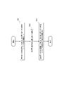
- the UE 100 is configured with a total of three SSSGs: Default SSSG, SSSG#x, and SSSG#y.
- the base station 200 the control unit 230 sets one common switching timer value in the UE 100 for SSSG#x and SSSG#y, which are not default SSSGs.
- UE 100 In period T11, UE 100 (control unit 120) monitors PDCCH using the default SSSG. UE 100 (communication section 110) receives a non-scheduling DCI instructing switching to SSSG#x in the last search space of period T11. UE 100 (control unit 120) starts a switching timer when receiving a non-scheduling DCI because HARQ processing does not occur in the case of non-scheduling DCI.
- UE 100 In period T12, UE 100 (control section 120) monitors PDCCH using SSSG#x while the switching timer is operating.
- SSSG#x is an SSSG with a longer search space period than the default SSSG.
- the switching timer expires, the UE 100 (control unit 120) switches to the default SSSG after the switching delay time (Switch delay) has elapsed.
- UE 100 In period T13, UE 100 (control unit 120) monitors PDCCH using the default SSSG. UE 100 (communication section 110) receives a scheduling DCI that instructs switching to SSSG#y in the last search space of period T13. Since HARQ processing occurs in the case of scheduling DCI, UE 100 (control unit 120) does not start the switching timer when scheduling DCI is received, and starts the switching timer at the timing (slot) at which switching to SSSG#y is performed. to start.
- the UE 100 (control unit 120) monitors the PDCCH using SSSG#y while the switching timer is operating.
- SSSG#y is an SSSG with a shorter search space period than the default SSSG.
- the switching timer expires, the UE 100 (control unit 120) switches to the default SSSG after the switching delay time (Switch delay) has elapsed.
- switch delay switching delay time
- UE 100 is configured with a total of three SSSGs: default SSSG (Default SSSG), SSSG#x for PDCCH skipping, and SSSG#y for PDCCH skipping.
- default SSSG Default SSSG
- SSSG#x for PDCCH skipping
- SSSG#y for PDCCH skipping.
- the base station 200 sets individual switching timer values in the UE 100 for SSSG#x and SSSG#y, which are not default SSSGs.
- UE 100 In period T21, UE 100 (control unit 120) monitors PDCCH using the default SSSG.
- UE 100 (communication section 110) receives a non-scheduling DCI instructing switching to SSSG#x in the last search space of period T11.
- UE 100 (control unit 120) switches independently to SSSG#x at the timing (slot) at which switching to SSSG#x is performed because SSSG#x to be switched to is an SSSG that supports PDCCH skipping. Start the timer (Switching timer-1).
- UE 100 In period T22, UE 100 (control unit 120) skips PDCCH monitoring while Switching timer-1 is in operation. When the Switching timer-1 expires, the UE 100 (control unit 120) switches to the default SSSG after the Switch delay has elapsed.
- UE 100 In period T23, UE 100 (control unit 120) monitors PDCCH using the default SSSG.
- UE 100 (communication section 110) receives a scheduling DCI that instructs switching to SSSG#y in the last search space of period T23.
- UE 100 (control unit 120) performs switching set independently to SSSG#y at the timing (slot) at which switching to SSSG#y is performed because SSSG#x to which switching is to be switched is an SSSG that supports PDCCH skipping.
- Start the timer (Switching timer-2).
- the timer value of Switching timer-2 is greater than the timer value of Switching timer-1.
- UE 100 In period T24, UE 100 (control unit 120) skips PDCCH monitoring while Switching timer-2 is in operation. When the Switching timer-2 expires, the UE 100 (control unit 120) switches to the default SSSG after the Switch delay has elapsed. Then, in period T25, UE 100 (control section 120) monitors PDCCH using the default SSSG.
- the base station 200 can grasp the switching destination SSSG. Therefore, timer-based switching can be performed for various SSSGs.
- the first to fourth operation examples described above may be implemented independently, or two or more operation examples may be combined and implemented. Also, the steps in the first to fourth operation examples do not necessarily have to be executed in chronological order according to the order described in the flow diagram or sequence diagram. For example, the steps in the operations may be performed out of order or in parallel with the order illustrated in the flow diagrams or sequence diagrams. Also, some steps in the operation may be omitted and additional steps may be added to the process. Furthermore, each operation flow described above is not limited to being implemented independently, but can be implemented by combining two or more operation flows. For example, some steps of one operation flow may be added to another operation flow, or some steps of one operation flow may be replaced with some steps of another operation flow.
- the base station 200 may include multiple units.
- the plurality of units may include a first unit hosting a higher layer included in the protocol stack and a second unit hosting a lower layer included in the protocol stack.
- the upper layers may include the RRC layer, the SDAP layer and the PDCP layer, and the lower layers may include the RLC layer, the MAC layer and the PHY layer.
- the first unit may be a CU (Central Unit), and the second unit may be a DU (Distributed Unit).
- the plurality of units may include a third unit that performs processing below the PHY layer.
- the second unit may perform processing above the PHY layer.
- the third unit may be an RU (Radio Unit).
- Base station 200 may be one of a plurality of units, and may be connected to other units of the plurality of units. Also, the base station 200 may be an IAB (Integrated Access and Backhaul) donor or an IAB node.
- IAB Integrated Access and Backhaul
- the mobile communication system 1 based on NR has been described as an example.
- the mobile communication system 1 is not limited to this example.
- the mobile communication system 1 may be a TS-compliant system of either LTE or another generation system (eg, 6th generation) of the 3GPP standard.
- Base station 200 may be an eNB that provides E-UTRA user plane and control plane protocol termination towards UE 100 in LTE.
- the mobile communication system 1 may be a system conforming to a TS of a standard other than the 3GPP standard.
- a program that causes a computer to execute each process performed by the UE 100 or the base station 200 may be provided.
- the program may be recorded on a computer readable medium.
- a computer readable medium allows the installation of the program on the computer.
- the computer-readable medium on which the program is recorded may be a non-transitory recording medium.
- the non-transitory recording medium is not particularly limited, but may be, for example, a recording medium such as CD-ROM or DVD-ROM.
- circuits that execute each process performed by the UE 100 or the base station 200 may be integrated, and at least a part of the UE 100 or the base station 200 may be configured as a semiconductor integrated circuit (chipset, SoC).
- “transmit” may mean performing at least one layer of processing in the protocol stack used for transmission, or physically transmitting the signal wirelessly or by wire. It may mean sending to Alternatively, “transmitting” may mean a combination of performing the at least one layer of processing and physically transmitting the signal wirelessly or by wire.
- “receive” may mean performing processing of at least one layer in the protocol stack used for reception, or physically receiving a signal wirelessly or by wire. may mean that Alternatively, “receiving” may mean a combination of performing the at least one layer of processing and physically receiving the signal wirelessly or by wire.
- “obtain/acquire” may mean obtaining information among stored information, and may mean obtaining information among information received from other nodes.
Landscapes
- Engineering & Computer Science (AREA)
- Signal Processing (AREA)
- Computer Networks & Wireless Communication (AREA)
- Mobile Radio Communication Systems (AREA)
Abstract
Priority Applications (5)
| Application Number | Priority Date | Filing Date | Title |
|---|---|---|---|
| EP22798907.6A EP4336931A1 (fr) | 2021-05-07 | 2022-04-26 | Dispositif de communication, station de base et procédé de communication |
| BR112023022958A BR112023022958A2 (pt) | 2021-05-07 | 2022-04-26 | Aparelho de comunicação, estação base, e, métodos de comunicação usado por um aparelho de comunicação |
| CN202280033287.0A CN117280816A (zh) | 2021-05-07 | 2022-04-26 | 通信装置、基站以及通信方法 |
| JP2023518673A JPWO2022234801A1 (fr) | 2021-05-07 | 2022-04-26 | |
| US18/500,911 US20240080170A1 (en) | 2021-05-07 | 2023-11-02 | Communication apparatus, base station, and communication method |
Applications Claiming Priority (2)
| Application Number | Priority Date | Filing Date | Title |
|---|---|---|---|
| JP2021079352 | 2021-05-07 | ||
| JP2021-079352 | 2021-05-07 |
Related Child Applications (1)
| Application Number | Title | Priority Date | Filing Date |
|---|---|---|---|
| US18/500,911 Continuation US20240080170A1 (en) | 2021-05-07 | 2023-11-02 | Communication apparatus, base station, and communication method |
Publications (1)
| Publication Number | Publication Date |
|---|---|
| WO2022234801A1 true WO2022234801A1 (fr) | 2022-11-10 |
Family
ID=83932721
Family Applications (1)
| Application Number | Title | Priority Date | Filing Date |
|---|---|---|---|
| PCT/JP2022/018985 WO2022234801A1 (fr) | 2021-05-07 | 2022-04-26 | Dispositif de communication, station de base et procédé de communication |
Country Status (6)
| Country | Link |
|---|---|
| US (1) | US20240080170A1 (fr) |
| EP (1) | EP4336931A1 (fr) |
| JP (1) | JPWO2022234801A1 (fr) |
| CN (1) | CN117280816A (fr) |
| BR (1) | BR112023022958A2 (fr) |
| WO (1) | WO2022234801A1 (fr) |
Citations (1)
| Publication number | Priority date | Publication date | Assignee | Title |
|---|---|---|---|---|
| JP2021503856A (ja) * | 2017-11-22 | 2021-02-12 | 鴻穎創新有限公司Fg Innovation Company Limited | 複数の帯域幅部分間の間欠受信動作 |
-
2022
- 2022-04-26 BR BR112023022958A patent/BR112023022958A2/pt unknown
- 2022-04-26 CN CN202280033287.0A patent/CN117280816A/zh active Pending
- 2022-04-26 WO PCT/JP2022/018985 patent/WO2022234801A1/fr active Application Filing
- 2022-04-26 JP JP2023518673A patent/JPWO2022234801A1/ja active Pending
- 2022-04-26 EP EP22798907.6A patent/EP4336931A1/fr active Pending
-
2023
- 2023-11-02 US US18/500,911 patent/US20240080170A1/en active Pending
Patent Citations (1)
| Publication number | Priority date | Publication date | Assignee | Title |
|---|---|---|---|---|
| JP2021503856A (ja) * | 2017-11-22 | 2021-02-12 | 鴻穎創新有限公司Fg Innovation Company Limited | 複数の帯域幅部分間の間欠受信動作 |
Non-Patent Citations (3)
| Title |
|---|
| "Revised WID UE Power Saving Enhancements for NR", 3GPP CONTRIBUTIONRP-200938 |
| MODERATOR (LENOVO): "Summary #2 of email discussion [101-e-NR-unlic-NRU- DL_Signals_and_Channels-01] on Search Space", 3GPP DRAFT; R1-2005011, 3RD GENERATION PARTNERSHIP PROJECT (3GPP), MOBILE COMPETENCE CENTRE ; 650, ROUTE DES LUCIOLES ; F-06921 SOPHIA-ANTIPOLIS CEDEX ; FRANCE, vol. RAN WG1, no. e-Meeting; 20200525 - 20200605, 6 June 2020 (2020-06-06), Mobile Competence Centre ; 650, route des Lucioles ; F-06921 Sophia-Antipolis Cedex ; France , XP051893687 * |
| VIVO: "Discussion on DCI-based power saving adaptation in connected mode", 3GPP DRAFT; R1-2100455, 3RD GENERATION PARTNERSHIP PROJECT (3GPP), MOBILE COMPETENCE CENTRE ; 650, ROUTE DES LUCIOLES ; F-06921 SOPHIA-ANTIPOLIS CEDEX ; FRANCE, vol. RAN WG1, no. e-Meeting; 20210125 - 20210205, 18 January 2021 (2021-01-18), Mobile Competence Centre ; 650, route des Lucioles ; F-06921 Sophia-Antipolis Cedex ; France , XP051970377 * |
Also Published As
| Publication number | Publication date |
|---|---|
| CN117280816A (zh) | 2023-12-22 |
| BR112023022958A2 (pt) | 2024-01-16 |
| EP4336931A1 (fr) | 2024-03-13 |
| US20240080170A1 (en) | 2024-03-07 |
| JPWO2022234801A1 (fr) | 2022-11-10 |
Similar Documents
| Publication | Publication Date | Title |
|---|---|---|
| KR101358608B1 (ko) | 롱텀 에볼루션 어드밴스트 캐리어 집적을 위한 불연속 수신 동작 방법 및 시스템 | |
| JP6174249B2 (ja) | ユーザ端末、無線基地局及び無線通信方法 | |
| KR20220100591A (ko) | 사용자 장비 및 스케줄링 노드, 사용자 장비를 위한 방법 및 스케줄링 노드를 위한 방법 | |
| EP3133890B1 (fr) | Procédé et dispositif de planification de données | |
| WO2022234801A1 (fr) | Dispositif de communication, station de base et procédé de communication | |
| WO2022234796A1 (fr) | Dispositif de communication, station de base et procédé de communication | |
| WO2022234834A1 (fr) | Dispositif de communication, station de base et procédé | |
| WO2022234838A1 (fr) | Dispositif de communication, station de base et procédé | |
| WO2022234835A1 (fr) | Équipement utilisateur, station de base et procédé de commande de communication | |
| JP2022172972A (ja) | ユーザ装置及び通信方法 | |
| WO2023127636A1 (fr) | Dispositif de communication et procédé de communication | |
| WO2022260103A1 (fr) | Dispositif de communication, station de base et procédé de communication | |
| WO2023112959A1 (fr) | Dispositif de communication, station de base et procédé de communication | |
| WO2022260106A1 (fr) | Dispositif de communication, station de base et procédé de communication | |
| WO2022260105A1 (fr) | Dispositif de communication, station de base et procédé de communication | |
| WO2023112961A1 (fr) | Dispositif de communication, station de base et procédé de communication | |
| WO2024071078A1 (fr) | Dispositif de communication, station de base et procédé de communication | |
| WO2024071076A1 (fr) | Dispositif de communication et procédé de communication | |
| WO2023127634A1 (fr) | Dispositif de communication, station de base et procédé de communication | |
| WO2023112960A1 (fr) | Dispositif de communication, station de base et procédé de communication | |
| US20240137973A1 (en) | Communication apparatus, base station, and communication method | |
| WO2023132273A1 (fr) | Dispositif de communication et procédé de communication | |
| WO2023048183A1 (fr) | Équipement utilisateur, station de base, et procédé de communication |
Legal Events
| Date | Code | Title | Description |
|---|---|---|---|
| 121 | Ep: the epo has been informed by wipo that ep was designated in this application |
Ref document number: 22798907 Country of ref document: EP Kind code of ref document: A1 |
|
| WWE | Wipo information: entry into national phase |
Ref document number: 202280033287.0 Country of ref document: CN |
|
| WWE | Wipo information: entry into national phase |
Ref document number: 2023518673 Country of ref document: JP |
|
| REG | Reference to national code |
Ref country code: BR Ref legal event code: B01A Ref document number: 112023022958 Country of ref document: BR |
|
| WWE | Wipo information: entry into national phase |
Ref document number: 2022798907 Country of ref document: EP |
|
| NENP | Non-entry into the national phase |
Ref country code: DE |
|
| ENP | Entry into the national phase |
Ref document number: 2022798907 Country of ref document: EP Effective date: 20231207 |
|
| ENP | Entry into the national phase |
Ref document number: 112023022958 Country of ref document: BR Kind code of ref document: A2 Effective date: 20231101 |