EP3145065A1 - Electrical machines - Google Patents
Electrical machines Download PDFInfo
- Publication number
- EP3145065A1 EP3145065A1 EP16181115.3A EP16181115A EP3145065A1 EP 3145065 A1 EP3145065 A1 EP 3145065A1 EP 16181115 A EP16181115 A EP 16181115A EP 3145065 A1 EP3145065 A1 EP 3145065A1
- Authority
- EP
- European Patent Office
- Prior art keywords
- permanent magnets
- electrical machine
- moveable
- winding
- moveable element
- Prior art date
- Legal status (The legal status is an assumption and is not a legal conclusion. Google has not performed a legal analysis and makes no representation as to the accuracy of the status listed.)
- Withdrawn
Links
- 238000004804 winding Methods 0.000 claims abstract description 60
- 230000005291 magnetic effect Effects 0.000 claims abstract description 54
- 230000003993 interaction Effects 0.000 claims description 14
- 238000000034 method Methods 0.000 claims description 10
- 230000005611 electricity Effects 0.000 claims description 2
- 238000010168 coupling process Methods 0.000 description 7
- 238000005859 coupling reaction Methods 0.000 description 7
- 230000008878 coupling Effects 0.000 description 6
- 238000001228 spectrum Methods 0.000 description 6
- 238000006243 chemical reaction Methods 0.000 description 3
- 230000004907 flux Effects 0.000 description 3
- XEEYBQQBJWHFJM-UHFFFAOYSA-N Iron Chemical compound [Fe] XEEYBQQBJWHFJM-UHFFFAOYSA-N 0.000 description 2
- 230000005294 ferromagnetic effect Effects 0.000 description 2
- 230000005540 biological transmission Effects 0.000 description 1
- 238000001816 cooling Methods 0.000 description 1
- 230000001808 coupling effect Effects 0.000 description 1
- 230000001747 exhibiting effect Effects 0.000 description 1
- 229910052742 iron Inorganic materials 0.000 description 1
- 238000005461 lubrication Methods 0.000 description 1
- 238000010248 power generation Methods 0.000 description 1
- 239000000758 substrate Substances 0.000 description 1
Images


Classifications
-
- H—ELECTRICITY
- H02—GENERATION; CONVERSION OR DISTRIBUTION OF ELECTRIC POWER
- H02K—DYNAMO-ELECTRIC MACHINES
- H02K16/00—Machines with more than one rotor or stator
- H02K16/02—Machines with one stator and two or more rotors
-
- H—ELECTRICITY
- H02—GENERATION; CONVERSION OR DISTRIBUTION OF ELECTRIC POWER
- H02K—DYNAMO-ELECTRIC MACHINES
- H02K49/00—Dynamo-electric clutches; Dynamo-electric brakes
- H02K49/10—Dynamo-electric clutches; Dynamo-electric brakes of the permanent-magnet type
- H02K49/102—Magnetic gearings, i.e. assembly of gears, linear or rotary, by which motion is magnetically transferred without physical contact
-
- H—ELECTRICITY
- H02—GENERATION; CONVERSION OR DISTRIBUTION OF ELECTRIC POWER
- H02K—DYNAMO-ELECTRIC MACHINES
- H02K7/00—Arrangements for handling mechanical energy structurally associated with dynamo-electric machines, e.g. structural association with mechanical driving motors or auxiliary dynamo-electric machines
- H02K7/10—Structural association with clutches, brakes, gears, pulleys or mechanical starters
- H02K7/11—Structural association with clutches, brakes, gears, pulleys or mechanical starters with dynamo-electric clutches
-
- H—ELECTRICITY
- H02—GENERATION; CONVERSION OR DISTRIBUTION OF ELECTRIC POWER
- H02K—DYNAMO-ELECTRIC MACHINES
- H02K21/00—Synchronous motors having permanent magnets; Synchronous generators having permanent magnets
- H02K21/12—Synchronous motors having permanent magnets; Synchronous generators having permanent magnets with stationary armatures and rotating magnets
- H02K21/14—Synchronous motors having permanent magnets; Synchronous generators having permanent magnets with stationary armatures and rotating magnets with magnets rotating within the armatures
- H02K21/16—Synchronous motors having permanent magnets; Synchronous generators having permanent magnets with stationary armatures and rotating magnets with magnets rotating within the armatures having annular armature cores with salient poles
-
- H—ELECTRICITY
- H02—GENERATION; CONVERSION OR DISTRIBUTION OF ELECTRIC POWER
- H02K—DYNAMO-ELECTRIC MACHINES
- H02K21/00—Synchronous motors having permanent magnets; Synchronous generators having permanent magnets
- H02K21/12—Synchronous motors having permanent magnets; Synchronous generators having permanent magnets with stationary armatures and rotating magnets
- H02K21/22—Synchronous motors having permanent magnets; Synchronous generators having permanent magnets with stationary armatures and rotating magnets with magnets rotating around the armatures, e.g. flywheel magnetos
Abstract
Description
- The present invention relates to electrical machines
- Mechanical gearboxes are extensively used to match the operating speed of prime-movers to the requirements of their loads for both increasing the rotational speed such as, for example, in a wind-powered generators or reducing rotational speed such as, for example, in an electric-ship propulsion arrangement. It is usually more cost and weight effective to employ a high-speed electrical machine in conjunction with a mechanical gearbox to achieve requisite speed and torque characteristics. However, while such a high-speed electrical machine in conjunction with a mechanical gearbox allows high system torque densities to be realised, such mechanical gearboxes usually require lubrication and cooling. Furthermore, reliability can also be a significant issue. Consequently, direct drive electrical machines are employed in applications where a mechanical gearbox cannot be used.
- There are various direct drive electrical machine topologies. One such topology is the permanent magnet rotary/linear homopolar (transverse-field) machine (TFM) that is known to offer the highest torque/force density. A rotary TFM has a torque density in the range of 40-60 kNm/m3. However, homopolar machines have inherently poor power factors that are of the order of 0.3-0.45, which makes them unsuitable for electrical power generation. Furthermore, they require a significantly higher converter volt-ampere rating for motor applications.
- It is an object of embodiments of the present invention to at least mitigate one or more of the above prior art problems.
- Accordingly, a first aspect of embodiments of the present invention provides an electrical machine comprising an inner moveable element and an outer moveable element arranged to interact in a magnetically geared manner via a plurality of permanent magnets associated with the inner moveable element; and a winding outwardly disposed relative to at least the inner moveable element arranged to interact magnetically with the fundamental harmonic of the magnetic field of the plurality of permanent magnets associated with the inner moveable element.
- A second aspect of embodiments of the present invention provides an electrical machine comprising a first moveable element and a second moveable element arranged to interact in a magnetically geared manner via asynchronous harmonics of the first and second pluralities of permanent magnets, and a winding arranged to interact magnetically with the fundamental harmonic of the magnetic field of the first plurality of permanent magnets associated with the first moveable element
- A third aspect of embodiments of the present invention provides a method of operating an electrical machine comprising the steps of producing a magnetically motivated geared interaction between first and second moveable elements of the electrical machine by modulating a magnetic field associated with the first moveable element; and energising a winding arranged to interact with the magnetic field associated with the first moveable element.
- A fourth aspect of embodiments of the present invention provides an electrical machine comprising first and second moveable elements that interact in a magnetically geared manner, and a winding arranged to interact with the first/fundamental harmonic of the magnetic field of the first plurality of permanent magnets associated with the first moveable element
- Advantageously, electrical or electromechanical machines according to embodiments of the present invention exhibit high torque and/or force densities that are significantly greater than conventional high-performance rotary/linear electrical machines and that are at least as high as homopolar machines or TFMs. However, unlike homopolar machines or TFMs, embodiments of the present invention have a relatively high power factor. Some embodiments exhibit a power factor of 0.9 or higher.
- Embodiments of the present invention will now be described, by way of example only, with reference to the accompanying drawings in which
-
Figure 1 depicts schematically a known rotary magnetic gear; -
Figure 2 illustrates magnetic harmonics associated with the assembly offigure 1 ; -
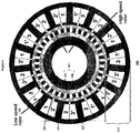
Figure 3 shows schematically a prior art assembly comprising an electrical generator combined with a magnetic gear; -
Figure 4 depicts schematically a combined electrical machine and magnetic gear according to an embodiment; -
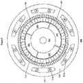
Figure 5 depicts a combined electrical machine and magnetic gear according to a preferred embodiment; -
Figure 6 shows an axial sectional view of the electrical machine offigure 5 ; -
Figure 7 illustrates magnetic harmonics associated with the combined electrical machine and magnetic gear offigures 5 and6 ; -
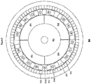
Figure 8 illustrates an electrical machine according to a still further embodiment; and -
Figure 9 magnetic harmonics associated with the combined electrical machine and magnetic gear offigure 8 . -
Figure 1 shows a rotarymagnetic gear 100 comprising a first orinner rotor 102, a second orouter rotor 104 and a number ofpole pieces 106, otherwise known as an interference or an interference means. Thefirst rotor 102 comprises asupport 108 bearing a respective first number ofpermanent magnets 110. In the illustrated magnetic gear, thefirst rotor 102 comprises 8 permanent magnets or 4 pole-pairs arranged to produce a spatially varying magnetic field. Thesecond rotor 104 comprises asupport 112 bearing a respective second number ofpermanent magnets 114. Thesecond rotor 104 illustrated comprises 46 permanent magnets or 23 pole-pairs arranged to produce a spatially varying field. The first and second numbers of permanent magnets are different. Accordingly, there will be little or no useful magnetic coupling or interaction between thepermanents magnets - The
pole pieces 106 are used to allow the fields of thepermanent magnets pole pieces 106 modulate the magnetic fields of thepermanent magnets -
Figure 2 shows aharmonic spectrum 200 of the spatial distribution of the magnetic flux density of thepermanent magnets 110 mounted on theinner rotor 102 of themagnetic gear 100 offigure 1 , in the airgap adjacent to thepermanent magnets 114 mounted on theouter rotor 104. It can be appreciated that thespectrum 200 comprises a first or fundamental harmonic 202 associated with thepermanent magnets 110 of thefirst rotor 102. Thepole pieces 106 modulate the magnetic field of thepermanent magnets 110. For thepermanent magnets 110, for example, this results in a relatively large asynchronous harmonic 204 having the same number of poles as thepermanent magnets 114, which enables coupling between the first 102 and the second 104 rotors such that movement of one induces movement of the other, in a geared manner - However, the
fundamental component 202 associated with thepermanent magnets 110 of thefirst rotor 102 is always present and is the source of the vast majority of electromagnetic losses associated with magnetic gears. - One skilled in the art understands how to select and design the
pole pieces 106, given the first 110 and second 114 permanent magnets, to achieve the necessary magnetic circuit or coupling such that gearing between the first 102 and second 104 rotors results as can be appreciated from, for example, K. Atallah, D. Howe, "A novel high-performance magnetic gear", IEEE Transactions on Magnetics, Vol. 37, No. 4, pp. 2844-2846, 2001 and K. Atallah, S. D. Calverley, D. Howe, "Design, analysis and realisation of a high performance magnetic gear", IEE Proceedings - Electric Power Applications, Vol. 151, pp. 135-143, 2004, which are incorporated herein by reference for all purposes and are included in the appendix. -
Figure 3 shows a knownassembly 300 comprising an electrical motor/generator 302 combined with amagnetic gear 304. Themagnetic gear 304 is substantially similar to that described above with reference tofigure 1 . Such an assembly is depicted and described in various embodiments inUS 6794781 . The electrical motor/generator 302 comprises acentral armature 306 with respective 3-phase winding 306a-3061. Theassembly 300 comprises a first orouter rotor 310 comprisingpermanent magnets 312 mounted on asubstrate 314 such as, for example, a back iron. Thepermanent magnets 312 are coupled, in a geared manner, to a number ofpermanent magnets 316 of a second/inner rotor 318. Thepermanent magnets 316 are mounted on asupport 320. The magnetic circuit or coupling established between thepermanent magnets 316 of theinner rotor 318 and thepermanent magnets 312 of theouter rotor 310 is realised using a plurality ofpole pieces 322 that are substantially equally circumferentially disposed relative to one another. The permanent magnets of thesecond rotor 318 couple with the 3-phase winding 306a-306l for motor/generator operations. Theouter rotor 310 is rotatable. Thepole pieces 322 are fixed, theinner rotor 318 is rotatable and thecentral armature 306 is fixed. -
Figure 4 shows the principle of operation of anelectrical machine 400 according to embodiments of the present invention. Theelectrical machine 400 comprises a first orinner rotor 402 having asupport 404 bearing a first plurality ofpermanent magnets 406. In the embodiment shown, permanent magnets having 10 poles are used. However, embodiments are not limited to using such a number of permanent magnets. Embodiments can be realised that use some other number of permanent magnets. Theelectrical machine 400 comprises asecond rotor 408 in the form of a plurality of ferromagnetic pole pieces. Thepole pieces 408 are arranged to magnetically couple thepermanent magnets 406 of the first/inner rotor 402 to a plurality ofpermanent magnets 410 that are fixed to a number oftooth tips 412 ofrespective teeth 414 thereby forming astator 416. In the embodiment shown, 60 permanent magnets are fixed to thetooth tips 412. The embodiment comprises 15teeth 414 withrespective tooth tips 412. It will be appreciated that embodiments are not limited to such a number of permanent magnets and teeth. Embodiments comprising some other number of permanent magnets and teeth can be realised. - The
pole pieces 408 are rotatable, that is, they form a rotor. Theinner rotor 402 is rotatable. Theteeth 414 and associatedpermanent magnets 410 are fixed. The coupling between thepermanent magnets 406 and thepermanent magnets 410 is realised using therotatable pole pieces 408. Associated with thestator 416 is a plurality of 3-phase windings permanent magnets 406 associated with theinner rotor 402. In the embodiment illustrated, the first/fundamental harmonic corresponding to thepermanent magnets 406 has 5 pole-pairs. - By utilising the hitherto unused fundamental harmonic associated with the
inner rotor 402, the torque density and efficiency of the electrical machine are vastly improved. Embodiments provide an improved power factor of substantially 0.9 (max. 1), which represents approximately a 200%-300% increase in the power factor of the electrical machine as compared to TFMs. -
Figure 5 shows anelectrical machine 500 according to a preferred embodiment of the present invention. Theelectrical machine 500 comprises aninner rotor 502 bearing a number ofpermanent magnets 504. In the illustrated embodiment, 4 pole permanent magnets are used. However, embodiments can be realised that use some other number of permanent magnets. Theelectrical machine 500 comprises anouter rotor 506 carrying a number offerromagnetic pole pieces 508. In the illustrated embodiment, theouter rotor 506 carries 23 pole pieces that enable magnetic coupling between thepermanent magnets 504 of theinner rotor 502 and a number ofpermanent magnets 510 that are mounted to astator 512. Thestator 512 comprises 3-phase windings 514a-514b associated with each of a plurality ofteeth 516. The windings magnetically couple with the first harmonic of thepermanent magnets 504. In preferred embodiment, the winding is 3-phase, but can equally well be some other type of winding such as, for example, 2-phase windings. The embodiment illustrated comprises 42 poles ofpermanents magnets 510 disposed on thestator 512. One skilled in the art understands that the crosses and points depicted with respect to the winding 514a-b illustrate the polarity of the coils. Thepole pieces 508 of theouter rotor 506 are arranged to provide gearing between theinner rotor 502 and theouter rotor 506. In preferred embodiments, the gearing is such that theinner rotor 502 is a relatively high-speed rotor and theouter rotor 506 is a relatively low speed rotor. Preferred embodiments have a gear ratio of 11.5:1. -
Figure 6 shows an axialsectional view 600 of theelectrical machine 500 shown infigure 5 . It can be seen that theelectrical machine 500 comprises ahousing 602 that supports, via a plurality ofbearings 604, acentral spindle 606 on which theinner rotor 502 and associatedpermanent magnets 504 are mounted for rotation therewith. Theouter rotor 506, comprising the associatedpole pieces 508, is rotatably mounted between thespindle 606 and thehousing 602 viarespective bearings 608. It can be appreciated that the armature orstator 512 is fixed and disposed outwardly relative to the inner and outer rotors. -
Figure 7 shows aspectrum 700 of the variation of magnetic flux density associated withpermanent magnets 504 in the airgap adjacent to thepermanent magnets 510 of the preferred embodiment of theelectrical machine 500 offigure 5 . It can be appreciated that thespectrum 700 comprises a first harmonic 702 associated with thepermanent magnets 504 of thefirst rotor 502. Thepole pieces 508 modulate the magnetic field of thepermanent magnets 504 and generate a relatively large asynchronous harmonic 704 that has the same number of poles as thepermanent magnets 510. In this embodiment, the first harmonic 702 associated with thepermanent magnets 704 of thefirst rotor 502 couples with thewindings 514a-b to establish electromechanical energy conversion, with a torque density comparable to TFMs, but with a much higher power factor -
Figure 8 shows anelectrical machine 800 according to a further embodiment. Theelectrical machine 800 comprises aninner rotor 802 bearing a plurality ofpermanent magnets 804. In the illustrated embodiment, permanent magnets having 4 poles are illustrated but some other number of permanent magnets could equally well be used. Theinner rotor 802 is preferably a relatively high-speed rotor. Theelectrical machine 800 comprises anouter rotor 806 bearing a plurality ofpermanent magnets 808. In the illustrated embodiment,permanent magnets 808 having 38 poles form part of theouter rotor 806. However, some other number of poles ofpermanent magnets 808 could be used. Theelectrical machine 800 comprises astationary armature 810 bearing a plurality ofpole pieces 812 and a 3-phase winding 814. The number of pole pieces in the embodiment is 21, although some other number of pole-pieces can be used in embodiments. It should be noted that the embodiment has been illustrated using a 3-phase winding. However, embodiments are not limited thereto. Embodiments can be realised that use some other windings such as, for example, a two phase winding. The second/outer rotor 806 forms a relatively low speed rotor that is magnetically coupled, in a geared manner, with the relatively high-speed first/inner rotor 802 via thepole pieces 812 of thestationary armature 810. One skilled in the art understands that the gear ratio is 19:1 and is related to the number of pole-pairs on theinner rotor 802 and the number of pole pieces. It will be appreciated that applying a current to the 3-phase windings 814 will cause the high-speed rotor 802 to rotate, which, in turn, will also cause thelow speed rotor 806 to rotate. Again, it can be appreciated that thewindings 814a-b couple with the first harmonic associated with thepermanent magnets 804 of the first/inner rotor 802 to establish electromechanical energy conversion, with a torque density comparable to TFMs, but with much higher power factor. -
Figure 9 shows aspectrum 900 of the variation of magnetic flux density associated withpermanent magnets 804 in the airgap adjacent to thepermanent magnets 808 of the preferred embodiment of theelectrical machine 800 offigure 8 . It can be appreciated that thespectrum 900 comprises a first harmonic 902 associated with thepermanent magnets 804 of thefirst rotor 802. Thepole pieces 812 modulate the magnetic field of thepermanent magnets 804 and generate a relatively large asynchronous harmonic 904 that has the same number of poles as thepermanent magnets 808. In this embodiment, the first or fundamental harmonic 902 associated with thepermanent magnets 904 of thefirst rotor 802 couples with the windings 814 to establish electromechanical energy conversion. - It will be appreciated that embodiments of the invention have been described with reference to electrical machines. One skilled in the art appreciates that such electrical machines can be used as motors or generators. Applying a 3-phase supply to the windings results in a geared electrical motor. However, rotating one of the
rotors 502/508 or 802/806 results in the electrical machine being used as a geared generator. Furthermore, although the above embodiments have been described with reference to using a 3-phase winding, embodiments are not limited to such an arrangement. Embodiments can be realised in which some other form of winding such as, for example, a 2-phase windings, is used. - Embodiments of the present invention can also be realised in the form of radial field rotary electrical machines and axial field rotary electrical machines.
- Disclosed herein are the following numbered clauses:
- 1. An electrical machine comprising:
- an inner moveable element and an outer moveable element arranged to interact in a magnetically geared manner via a plurality of permanent magnets associated with the inner moveable element; and
- a winding outwardly disposed relative to at least the inner moveable element arranged to interact magnetically with the fundamental harmonic of the magnetic field of the plurality of permanent magnets associated with the inner moveable element.
- 2. An electrical machine as disclosed in
clause 1 in which the winding is inwardly disposed relatively to the outer moveable element. - 3. An electrical machine as disclosed in
clause 1 in which the winding is outwardly disposed relatively to the outer moveable element. - 4. An electrical machine as disclosed in any preceding clause in which the outer moveable element comprises a plurality of pole-pieces to influence said magnetically geared interaction.
- 5. An electrical machine as disclosed in any of
clauses 1 to 3 further comprises a plurality of pole-pieces disposed between the inner and outer moveable elements to influence said magnetically geared interaction. - 6. An electrical machine as disclosed in any preceding clause in which the outer moveable element is arranged to carry the winding.
- 7. An electrical machine comprising a first set of permanent magnets, a plurality of pole-pieces and a second set of permanent magnets arranged in a magnetically geared manner; and a winding arranged to interact with the fundamental space harmonic of the first set of permanent magnets.
- 8. An electrical machine as disclosed in clause 7 in which the first set of permanent magnets are associated with a first rotor/translator for rotation/translation therewith.
- 9. An electrical machine as disclosed in either of
clauses 7 and 8 in which the second set of permanent magnets is disposed in a fixed relationship relative to the winding. - 10. An electrical machine as disclosed in any of clauses 7 to 9 in which the plurality of pole pieces is disposed in a fixed relationship relative to the windings.
- 11. An electrical machine as disclosed in any of clauses 7 to 10 in which the plurality of pole pieces is disposed in a fixed relationship with a rotor/translator for rotation/translation therewith.
- 12. An electrical machine as disclosed in any of clauses 7 to 11 in which the second plurality of permanent magnets is disposed in a fixed relationship with a rotor/translator for rotation/translation therewith.
- 13. An electrical machine comprising a first moveable element and a second moveable element arranged to interact in a magnetically geared manner via asynchronous harmonics of the first and second pluralities of permanent magnets, and a winding arranged to interact magnetically with the fundamental harmonic of the magnetic field of the first plurality of permanent magnets associated with the first moveable element.
- 14. An electrical machine as disclosed in
clause 13 in which the first moveable element is an inner rotor or an inner translator bearing the first plurality of permanent magnets. - 15. An electrical machine as disclosed in
clause 13 in which the second moveable element is an outer rotor or outer translator bearing a plurality of pole pieces. - 16. An electrical machine as disclosed in clause 15 in which the second plurality of permanent magnets are disposed in a fixed relationship relative to the winding.
- 17. An electrical machine as disclosed in any of
clauses 13 to 16 in which the second moveable element comprises a plurality of permanent magnets. - 18. An electrical machine as disclosed in clause 17 in which the plurality of pole-pieces are disposed in a fixed relationship relative to the winding.
- 19. A method of operating an electrical machine comprising the steps of producing a magnetically motivated geared interaction between first and second moveable elements of the electrical machine by modulating a magnetic field associated with the first moveable element; and energising a winding arranged to interact with the magnetic field associated with the first moveable element.
- 20. A method as disclosed in clause 19 wherein at least one of said energising and the winding are arranged to interact with the first or fundamental space harmonic of the magnetic field associated with the first moveable element.
- 21. A method of generating electricity using an electrical machine as disclosed in any of
clauses 1 to 16, comprising the steps of moving at least said second moveable element to induce movement of said first moveable element to cause a magnetic interaction between the first or fundamental harmonic of the magnetic field associated with the first moveable element and the winding. - 22. An electrical machine comprising first (502, 504; 802, 804) and second moveable elements (506; 806) that interact in a magnetically geared manner, and a winding (514; 814) arranged to interact with the first/fundamental harmonic of the magnetic field of the first plurality of permanent magnets (504; 804) associated with the first moveable element (502, 504; 802, 804).
- 23. An electrical machine as disclosed in clause 22 comprising a plurality of pole-pieces (508; 812) for modulating the magnetic field of the at least one of the first plurality of permanent magnets and a second plurality of permanent magnets (504,510) and (804,808) to enable said geared interaction.
- 24. An electrical machine as disclosed in clause 22 in which the second moveable element (506; 806) comprises a plurality of pole-pieces (508) or a plurality of permanent magnets (808).
- 25. An electrical machine as disclosed in any of clauses 22 to 24 in which the first moveable element is disposed inwardly of the second moveable element.
- 26. An electrical machine as disclosed in any of clauses 22 to 25 wherein the windings (514; 814) are mounted on a stationary armature (512; 810) that bears a second plurality of fixed permanents magnets (510) or plurality of pole-pieces (812).
- 27. An electrical machine as disclosed in any of clauses 22 to 26 in which the winding is operable to receive a current to produce said interaction with the fundamental harmonic of the first plurality of permanents magnets (504; 804).
- 28. An electrical machine as disclosed in any of clauses 22 to 27 in which the winding is operable to generate power in response to said interaction with the fundamental harmonic of the first plurality of permanent magnets (504; 804).
- 29. An electrical machine as disclosed in any of clauses 22 to 28 in which the first and second moveable elements are linearly moveable translators.
- 30. An electrical machine as disclosed in any of clauses 22 to 29 in which the first and second moveable elements are rotationally moveable rotors.
- 31. An electrical machine substantially as described herein with reference to and/or as illustrated in any of
figures 4 to 9 . - 32. An electrical machine comprising
- a. a first rotor/translator having an associated first set of permanent magnets exhibiting a respective first number of pole-pairs;
- b. a second set of permanent magnets having a respective second number of pole-pairs such the first and second numbers of pole-pairs are different;
- c. a plurality of pole pieces arranged to modulate the fields of the first and second sets of permanent magnets to produce mutually matching pole-pairs enabling magnetic coupling and hence torque transmission, between the first and second sets of permanent magnets;
- d. a winding selected to magnetically couple with the first harmonic of the permanent magnets of the first rotor/translator.
- 33. An electrical machine as disclosed in
clause 32 in which the second set of permanent magnets and a multi-phase winding are mounted on a stationary armature. - 34. An electrical machine as disclosed in either of
clauses 32 and 33 in which the pole-pieces are mounted on the second moveable rotor/translator. - 35. An electrical machine as disclosed in clause 34 in which the rotor/translator bearing the pole-pieces is moveable at a speed that is lower than that at which the first rotor/translator is moveable.
- 36. An electrical machine as disclosed in
clause 32 in which the pole-pieces and a multi-phase winding are mounted on a stationary armature. - 37. An electrical machine as disclosed in either of
clauses - 38. An electrical machine as disclosed in clause 37 in which the rotor/translator bearing the second plurality of permanent magnets is moveable at a speed that is lower than that at which the first rotor/translator is moveable.
- 39. An electrical machine as disclosed in any preceding clause in which the first and second moveable rotors and stationary armature are cylindrically shaped, and concentrically disposed relative to an axis of rotation thereby forming a radial field rotary electrical machine.
- 40. An electrical machine as disclosed in any preceding clause, where the first and second moveable rotors and stationary armature are at least one of annular or disc shaped, and axially disposed along the axis of rotation thereby forming an axial field rotary electrical machine.
- 41. An electrical machine as disclosed in any preceding clause comprising a power factor of at least 0.9.


Claims (15)
- An electrical machine comprising:first and second moveable elements that interact in a magnetically geared manner,the first moveable element having a first plurality of permanent magnets associated therewith; anda winding mounted on a stationary armature that bears a plurality of pole pieces;wherein the winding is arranged to interact with the first/fundamental harmonic of the magnetic field of the first plurality of permanent magnets.
- The electrical machine of claim 1, wherein the plurality of pole pieces are arranged to modulate the magnetic field of at least one of the first plurality of permanent magnets and a second plurality of permanent magnets to enable the magnetically geared interaction, and optionally wherein the second plurality of permanent magnets are associated with the second moveable element.
- The electrical machine of any preceding claim, wherein the winding is operable to receive a current to produce the interaction with the first/fundamental harmonic of the first plurality of permanent magnets, and optionally wherein the interaction is a production of torque for rotating the first moveable element.
- The electrical machine of any preceding claim, wherein the winding is operable to generate power in response to the interaction with the first/fundamental harmonic of the first plurality of permanent magnets.
- The electrical machine of any preceding claim, wherein the first and second moveable elements are linearly moveable translators.
- The electrical machine of any of claims 1 to 4, wherein the first and second moveable elements are rotationally moveable rotors, and optionally wherein the first moveable element is disposed inwardly of the second moveable element.
- The electrical machine of claim 6, wherein the stationary armature is disposed between the first and second moveable elements.
- The electrical machine of any preceding claim, wherein the gear ratio is such that the second moveable element moves at a lower speed than the first moveable element.
- The electrical machine of any preceding claim, wherein the first and second moveable rotors and stationary armature are cylindrically shaped, and concentrically disposed relative to an axis of rotation, thereby forming a radial field rotary electrical machine.
- The electrical machine of any of claim 1 to 8, wherein the first and second moveable rotors and stationary armature at least one of annular or disc shaped, and axially disposed along an axis of rotation, thereby forming an axial field rotary electrical machine.
- The electrical machine of any preceding claim comprising a power factor of at least 0.9.
- A method of generating kinetic energy using an electrical machine comprising first and second moveable elements that interact in a magnetically geared manner, wherein a first plurality of permanent magnets is associated with the first moveable element, and a winding is mounted on a stationary armature that bears a plurality of pole pieces, wherein the winding is arranged to interact with the first/fundamental harmonic of the magnetic field of the first plurality of permanent magnets, the method comprising:energising the winding, wherein energising the winding induces movement of the first moveable element and movement of the first moveable element induces movement of the second moveable element.
- The method of claim 12, wherein the second movable element has a second plurality of permanent magnets associated therewith.
- A method of generating electricity using an electrical machine comprising first and second moveable elements that interact in a magnetically geared manner, wherein a first plurality of permanent magnets is associated with the first moveable element, and a winding is mounted on a stationary armature that bears a plurality of pole pieces, wherein the winding is arranged to interact with the first/fundamental harmonic of the magnetic field of the first plurality of permanent magnets, the method comprising:moving the second moveable element to induce movement of the first moveable element to cause a magnetic interaction between the first orfundamental harmonic of the magnetic field associated with the first moveable element and the winding to induce a voltage in the winding.
- The method of claim 14, wherein the second movable element has a second plurality of permanent magnets associated therewith.
Applications Claiming Priority (2)
| Application Number | Priority Date | Filing Date | Title |
|---|---|---|---|
| GB0607994A GB2437568B (en) | 2006-04-24 | 2006-04-24 | Electrical machines |
| EP07732496.0A EP2011215B1 (en) | 2006-04-24 | 2007-04-23 | Electrical machines |
Related Parent Applications (2)
| Application Number | Title | Priority Date | Filing Date |
|---|---|---|---|
| EP07732496.0A Division-Into EP2011215B1 (en) | 2006-04-24 | 2007-04-23 | Electrical machines |
| EP07732496.0A Division EP2011215B1 (en) | 2006-04-24 | 2007-04-23 | Electrical machines |
Publications (1)
| Publication Number | Publication Date |
|---|---|
| EP3145065A1 true EP3145065A1 (en) | 2017-03-22 |
Family
ID=36581085
Family Applications (2)
| Application Number | Title | Priority Date | Filing Date |
|---|---|---|---|
| EP16181115.3A Withdrawn EP3145065A1 (en) | 2006-04-24 | 2007-04-23 | Electrical machines |
| EP07732496.0A Active EP2011215B1 (en) | 2006-04-24 | 2007-04-23 | Electrical machines |
Family Applications After (1)
| Application Number | Title | Priority Date | Filing Date |
|---|---|---|---|
| EP07732496.0A Active EP2011215B1 (en) | 2006-04-24 | 2007-04-23 | Electrical machines |
Country Status (10)
| Country | Link |
|---|---|
| US (2) | US7982351B2 (en) |
| EP (2) | EP3145065A1 (en) |
| JP (2) | JP5204094B2 (en) |
| CN (2) | CN101485068B (en) |
| CA (1) | CA2650397C (en) |
| DK (1) | DK2011215T3 (en) |
| ES (1) | ES2595327T3 (en) |
| GB (1) | GB2437568B (en) |
| NO (2) | NO337848B1 (en) |
| WO (1) | WO2007125284A1 (en) |
Families Citing this family (96)
| Publication number | Priority date | Publication date | Assignee | Title |
|---|---|---|---|---|
| GB2457226B (en) * | 2008-01-11 | 2013-01-09 | Magnomatics Ltd | Drives for sealed systems |
| GB0810096D0 (en) * | 2008-06-03 | 2008-07-09 | Magnomatics Ltd | Electrical machines |
| GB0807388D0 (en) | 2008-04-23 | 2008-05-28 | Magnomatics Ltd | Electrical machines |
| GB0810097D0 (en) * | 2008-06-03 | 2008-07-09 | Magnomatics Ltd | Magnetic gear |
| GB2457682B (en) * | 2008-02-21 | 2012-03-28 | Magnomatics Ltd | Variable magnetic gears |
| GB0813173D0 (en) * | 2008-02-21 | 2008-08-27 | Magnomatics Ltd | Wind turbine power train |
| CN101976905B (en) * | 2008-04-21 | 2013-03-20 | 许晓华 | Direct-drive composite permanent magnet motor |
| US20090288893A1 (en) * | 2008-05-09 | 2009-11-26 | John C. Wyall | Controllerless electric drive system |
| GB0808524D0 (en) * | 2008-05-12 | 2008-06-18 | Magnomatics Ltd | Magnetic pole-piece structure |
| US8847464B2 (en) * | 2008-06-12 | 2014-09-30 | General Electric Company | Electrical machine with improved stator flux pattern across a rotor that permits higher torque density |
| US20100032952A1 (en) * | 2008-08-08 | 2010-02-11 | Hatch Gareth P | Turbine generator having direct magnetic gear drive |
| EP2161821B1 (en) | 2008-09-03 | 2020-06-17 | General Electric Company | Magnetically geared generator |
| US7804215B2 (en) * | 2008-09-30 | 2010-09-28 | General Electric Company | Integrated cooling concept for magnetically geared machine |
| WO2010082893A1 (en) | 2009-01-15 | 2010-07-22 | Volvo Technology Corporation | Electromagnetic, continuously variable transmission power split turbo compound and engine and vehicle comprising such a turbo compound |
| ITBO20090075A1 (en) * | 2009-02-13 | 2010-08-14 | Magneti Marelli Spa | ELECTRIC MACHINE WITH SINGLE STATOR AND TWO ROTORS BETWEEN THEM INDEPENDENT AND ROAD VEHICLE PROVIDED WITH THIS ELECTRIC MACHINE |
| GB2468888B (en) | 2009-03-26 | 2013-11-06 | Magnomatics Ltd | Marine propulsion device with an electrical machine having integral magnetic gearing |
| GB0905343D0 (en) | 2009-03-27 | 2009-05-13 | Ricardo Uk Ltd | A flywheel |
| GB0905345D0 (en) | 2009-03-27 | 2009-05-13 | Ricardo Uk Ltd | A flywheel |
| GB0905344D0 (en) | 2009-03-27 | 2009-05-13 | Ricardo Uk Ltd | A flywheel |
| DE102009024261B4 (en) | 2009-06-05 | 2014-10-16 | Sew-Eurodrive Gmbh & Co Kg | Electric machine |
| GB0920148D0 (en) * | 2009-11-17 | 2009-12-30 | Magnomatics Ltd | Magnetically geared machine for marine generation |
| WO2011061496A2 (en) | 2009-11-17 | 2011-05-26 | Ricardo Uk Limited | A coupler |
| TWI406480B (en) * | 2010-01-13 | 2013-08-21 | Ind Tech Res Inst | Transmission apparatus |
| CN102195442B (en) * | 2010-03-05 | 2013-09-04 | 江建中 | Magnetic field modulation type magnetic gear |
| DK2572440T3 (en) | 2010-05-17 | 2021-11-22 | Magnomatics Ltd | MAGNETIC DRIVE MECHANISM |
| WO2011160833A1 (en) | 2010-06-22 | 2011-12-29 | Volvo Lastvagnar Ab | A turbo compound transmission and a method for controlling a turbo compound transmission |
| FR2963501B1 (en) * | 2010-07-29 | 2012-08-31 | Valeo Equip Electr Moteur | SYNCHRONOUS ROTOR ELECTRIC MACHINE WITH DOUBLE EXCITATION ROTOR |
| US20120098374A1 (en) * | 2010-10-25 | 2012-04-26 | Alvaro Jorge Mari Curbelo | Variable-speed magnetic coupling and method for control |
| GB201019473D0 (en) | 2010-11-17 | 2010-12-29 | Ricardo Uk Ltd | An improved coupler |
| US8319365B2 (en) * | 2010-12-17 | 2012-11-27 | General Electric Company | System and method to provide constant speed mechanical output in a machine |
| CN102032119A (en) * | 2010-12-20 | 2011-04-27 | 中国科学院深圳先进技术研究院 | Wind driven generator integrating magnetic gear with outer rotor |
| US20130342057A1 (en) * | 2011-01-17 | 2013-12-26 | Lord Corporation | Linear-rotating magnet energy harvester |
| JP5286373B2 (en) * | 2011-01-28 | 2013-09-11 | 株式会社日立製作所 | Magnetic gear |
| GB201101678D0 (en) | 2011-02-01 | 2011-03-16 | Rolls Royce Plc | A cooling arrangement for a magnetic gearbox |
| GB2488129A (en) | 2011-02-16 | 2012-08-22 | Rolls Royce Plc | Modulated field electromagnetic machine |
| JP5722690B2 (en) * | 2011-04-19 | 2015-05-27 | T.K Leverage株式会社 | Power generator |
| GB201106768D0 (en) | 2011-04-20 | 2011-06-01 | Ricardo Uk Ltd | An energy storage system |
| WO2012168977A1 (en) * | 2011-06-09 | 2012-12-13 | 東芝三菱電機産業システム株式会社 | Rotating electric machine |
| US9337708B2 (en) | 2011-06-27 | 2016-05-10 | Hitachi, Ltd. | Magnetic gear-type electric rotating machine |
| CN102868268A (en) * | 2011-07-03 | 2013-01-09 | 余虹锦 | Novel air gap magnetic field electromagnetic modulation permanent magnet motor with double squirrel cage structure |
| WO2013016159A2 (en) | 2011-07-22 | 2013-01-31 | Regal Beloit Epc Inc. | Magnetic transmission |
| CN103038986B (en) * | 2011-07-29 | 2015-06-10 | 松下电器产业株式会社 | Electric motor |
| CN103748772B (en) | 2011-08-11 | 2016-06-08 | 东芝三菱电机产业系统株式会社 | Electric rotating machine |
| JP5858399B2 (en) * | 2011-11-11 | 2016-02-10 | 国立大学法人大阪大学 | Magnetic deceleration mechanism and low-speed rotor magnetic deceleration rotation control method |
| WO2013091669A1 (en) * | 2011-12-21 | 2013-06-27 | Volvo Lastvagnar Ab | A turbo compound transmission and a method for controlling a turbo compound transmission |
| EP2629407B1 (en) * | 2012-02-17 | 2014-12-24 | Bell Helicopter Textron Inc. | Electrical generator for rotating structure |
| EP2825408B1 (en) * | 2012-03-12 | 2016-09-07 | Schaeffler Technologies AG & Co. KG | Actuator device for torque transmission equipment |
| CN103378711B (en) * | 2012-04-17 | 2015-05-06 | 余虹锦 | Dual mechanical port magnetic conductance harmonic type electromagnetic gear composite permanent magnet motor |
| GB2508416A (en) | 2012-11-30 | 2014-06-04 | Univ Sheffield | Reducing dominant undesirable harmonics in an electric machine |
| JP6093592B2 (en) * | 2013-02-22 | 2017-03-08 | 株式会社Ihi | Magnetic wave gear device |
| GB201308270D0 (en) | 2013-05-08 | 2013-06-12 | Magnomatics Ltd | Methods and apparatus for rotor position estimation |
| WO2015103781A1 (en) * | 2014-01-13 | 2015-07-16 | 卢敏 | Salient-pole magnetic-conductance harmonic-wave electromagnetic gear three-phase alternating current composite motor |
| US10418927B2 (en) | 2014-02-11 | 2019-09-17 | Magnomatics Limited | Magnetic gear system and method for reducing transmission of torque pulsation |
| JP6265569B2 (en) * | 2014-03-12 | 2018-01-24 | 株式会社Ihi | Annular magnetic pole member and magnetic wave gear device |
| DE102014104494A1 (en) | 2014-03-31 | 2015-10-01 | Momentum Technologies Gmbh | Drive system with electric motor and gearbox |
| JP6257114B2 (en) * | 2014-05-20 | 2018-01-10 | 株式会社Ihi | Magnetic wave gear device |
| CN104065242B (en) * | 2014-06-27 | 2017-01-25 | 南京艾凌节能技术有限公司 | Integrated permanent magnet variable speed reducer |
| US10145215B2 (en) * | 2014-12-31 | 2018-12-04 | Halliburton Energy Services, Inc. | Drill bit with electrical power generator |
| US9667126B2 (en) * | 2015-01-05 | 2017-05-30 | Langham Automatic Co., Ltd. | Motor |
| CN104600930B (en) * | 2015-01-08 | 2017-06-16 | 东南大学 | Permanent magnet excitation brushless dual-feedback wind power generator |
| WO2016180750A1 (en) | 2015-05-08 | 2016-11-17 | Rolls-Royce Ab | A marine vessel propulsion device, a pod unit and a marine vessel. |
| US10724999B2 (en) | 2015-06-04 | 2020-07-28 | Rolls-Royce Corporation | Thermal spray diagnostics |
| GB2539202A (en) * | 2015-06-08 | 2016-12-14 | Elumotion Ltd | Rotary actuator |
| CN104901510B (en) * | 2015-07-01 | 2018-02-13 | 大连交通大学 | A kind of permanent magnet gear transmission device |
| GB201520131D0 (en) | 2015-11-16 | 2015-12-30 | Rolls Royce Plc | Variable gear ratio electrical machine |
| GB2549448A (en) * | 2016-01-13 | 2017-10-25 | Magnomatics Ltd | A magnetically geared apparatus |
| EP3484795A4 (en) | 2016-07-14 | 2020-07-22 | FlexLink AB | Magnetic transmission for conveyor |
| US10513986B2 (en) | 2016-10-05 | 2019-12-24 | Rolls-Royce North American Technologies, Inc. | Counter-rotating electric generator in turbine engine |
| US10312781B2 (en) * | 2016-10-05 | 2019-06-04 | Rolls-Royce North American Technologies, Inc. | Multiple coil electric generator in turbine engine |
| JP6954581B2 (en) * | 2016-11-11 | 2021-10-27 | 株式会社プロスパイン | Generator with rotary speed booster |
| US10505431B1 (en) | 2017-03-06 | 2019-12-10 | Harold O. Hosea | Brushless dual rotor electromagnetic induction motor |
| CN107070031B (en) * | 2017-05-15 | 2020-07-14 | 华中科技大学 | Rotor, stator and multi-working harmonic permanent magnet motor |
| ES2941256T3 (en) | 2018-01-12 | 2023-05-19 | Carrier Corp | Double Rotor Coreless Electromagnetic Machine |
| DE102018110151A1 (en) * | 2018-04-26 | 2019-10-31 | Linz Center Of Mechatronics Gmbh | Electric machine with electric motor and magnetic gear |
| RU2706797C1 (en) * | 2018-06-21 | 2019-11-21 | Общество С Ограниченной Ответственностью "Научно-Производственное Предприятие Электромеханические Технологии" | Magnetic gearbox |
| KR102062461B1 (en) * | 2018-07-30 | 2020-02-20 | 한국교통대학교산학협력단 | A skew angle derivation method for reduction of cogging torque of a magnetic geared synchronous motor |
| DE102018133718A1 (en) * | 2018-12-31 | 2020-07-02 | Henk B.V. | Transport device for transporting at least one object and / or one person |
| CN111525768B (en) | 2019-02-01 | 2023-02-28 | 香港中文大学 | Human body kinetic energy collecting device and conversion method thereof |
| US11046404B2 (en) * | 2019-07-31 | 2021-06-29 | Abb Schweiz Ag | Dual propeller drive system for a ship |
| US11296588B2 (en) * | 2019-10-15 | 2022-04-05 | Darrell Schmidt Enterprises, Inc. | Magnetic coupler |
| CN112803691A (en) | 2019-11-13 | 2021-05-14 | 通用汽车环球科技运作有限责任公司 | Axial flux motor with distributed windings |
| CN112821702A (en) | 2019-11-15 | 2021-05-18 | 通用汽车环球科技运作有限责任公司 | Hybrid stator core piece design for axial flux motor |
| JP2021112945A (en) * | 2020-01-17 | 2021-08-05 | 三菱重工業株式会社 | Electric vehicle |
| JP7413042B2 (en) * | 2020-01-24 | 2024-01-15 | 三菱重工業株式会社 | Outer diameter side magnet field and magnetic gear |
| JP7365250B2 (en) | 2020-01-24 | 2023-10-19 | 三菱重工業株式会社 | Magnetic geared rotating electric machine and stator manufacturing method |
| WO2021189050A1 (en) * | 2020-03-20 | 2021-09-23 | Sanders Daniel Lee | A universal core electrical machine |
| CN114552815A (en) | 2020-11-26 | 2022-05-27 | 通用汽车环球科技运作有限责任公司 | Direct contact cooling of axial flux machine stator |
| CN112615517A (en) * | 2020-11-30 | 2021-04-06 | 珠海格力电器股份有限公司 | Magnetic gear assembly and composite motor with same |
| WO2022118598A1 (en) * | 2020-12-02 | 2022-06-09 | パナソニックIpマネジメント株式会社 | Magnetic-geared motor and magnetic gear |
| DE202021100986U1 (en) | 2021-02-26 | 2022-05-31 | Frank Ranostaj | Bicycle support drive, in particular with an electric drive, in particular for a bicycle |
| JP2022155119A (en) | 2021-03-30 | 2022-10-13 | 三菱重工業株式会社 | Magnetic geared rotary machine, power generation system and magnetic pole piece rotor |
| WO2022265574A2 (en) * | 2021-06-14 | 2022-12-22 | Nanyang Technological University | Flux-modulated machine |
| JP2023042363A (en) | 2021-09-14 | 2023-03-27 | 三菱重工業株式会社 | Magnetic geared rotary machine, power generation system, and drive system |
| WO2023102171A2 (en) * | 2021-12-02 | 2023-06-08 | Matthew Moran | High-efficiency machine |
| DE102022203842A1 (en) | 2022-04-19 | 2023-10-19 | Zf Friedrichshafen Ag | Electric motor device |
| JP2024047200A (en) * | 2022-09-26 | 2024-04-05 | 三菱重工業株式会社 | Stator and method for manufacturing the same |
Citations (6)
| Publication number | Priority date | Publication date | Assignee | Title |
|---|---|---|---|---|
| EP0945963A2 (en) * | 1998-03-25 | 1999-09-29 | Nissan Motor Co., Ltd. | Motor/generator |
| EP1117173A2 (en) * | 2000-01-17 | 2001-07-18 | Nissan Motor Company Limited | Motor/Generator |
| EP1353436A2 (en) * | 2002-04-13 | 2003-10-15 | ROLLS-ROYCE plc | A compact electrical machine |
| US20040119373A1 (en) * | 2002-04-01 | 2004-06-24 | Kan Akatsu | Electrical rotating machine having two rotors driven by means of compound current |
| WO2004079884A1 (en) * | 2003-03-07 | 2004-09-16 | Kabushiki Kaisha Yaskawa Denki | In-vacuum drive device and substrate transportation system using the same |
| EP1528659A2 (en) * | 2003-10-10 | 2005-05-04 | Nissan Motor Co., Ltd. | Magnetic circuit structure for rotary electric machine |
Family Cites Families (23)
| Publication number | Priority date | Publication date | Assignee | Title |
|---|---|---|---|---|
| DE2417054C3 (en) | 1974-04-08 | 1983-02-10 | Siemens AG, 1000 Berlin und 8000 München | Circuit arrangement with two interlinked circuit systems |
| FR2517137B1 (en) * | 1981-11-25 | 1985-11-15 | Cibie Pierre | ROTATING ELECTRICAL MACHINE FORMING IN PARTICULAR A SPEED VARIATOR OR TORQUE CONVERTER |
| GB9309689D0 (en) * | 1993-05-11 | 1993-06-23 | Flack Roy E | Electromagnetic transimssion systems,motors and generators |
| DE4405701A1 (en) * | 1994-02-23 | 1995-08-24 | Philips Patentverwaltung | Magnetic gear with several magnetically interacting, relatively movable parts |
| DE4408719C1 (en) * | 1994-03-15 | 1995-07-06 | Volkswagen Ag | Combined electric generator and motor for vehicle hybrid drive |
| JP3427511B2 (en) * | 1994-10-11 | 2003-07-22 | 株式会社デンソー | Dual-shaft output motor |
| FR2742939B1 (en) * | 1995-12-21 | 1998-03-06 | Jeumont Ind | MODULAR DISCOID ELECTRIC MACHINE |
| US5793136A (en) * | 1996-06-05 | 1998-08-11 | Redzic; Sabid | Differential motor/generator apparatus |
| DE19652490A1 (en) * | 1996-12-17 | 1998-06-18 | Philips Patentverwaltung | Magnetic gear |
| US6121705A (en) * | 1996-12-31 | 2000-09-19 | Hoong; Fong Chean | Alternating pole AC motor/generator with two inner rotating rotors and an external static stator |
| DE19743380C1 (en) | 1997-09-30 | 1999-03-25 | Emf 97 Gmbh | Energy conversion reluctance motor |
| JP3480302B2 (en) * | 1998-03-25 | 2003-12-15 | 日産自動車株式会社 | Rotating electric machine |
| JP2000060091A (en) * | 1998-08-06 | 2000-02-25 | Ebara Corp | Dynamo electric machine |
| JP3480439B2 (en) * | 1999-09-27 | 2003-12-22 | 日産自動車株式会社 | Control device for rotating electric machine |
| JP3580194B2 (en) * | 1999-10-04 | 2004-10-20 | 日産自動車株式会社 | Assembly structure of rotating electric machine |
| JP4269544B2 (en) * | 2000-09-14 | 2009-05-27 | 株式会社デンソー | Multi-rotor synchronous machine |
| US7259492B2 (en) * | 2001-09-27 | 2007-08-21 | Tai-Her Yang | Rotor axial activation modulation of electric machinery due to reverse torque |
| AUPS083702A0 (en) * | 2002-03-04 | 2002-03-21 | Darday, Stephen | Magnetic torque converter |
| JP2003281858A (en) * | 2002-03-22 | 2003-10-03 | Alpine Electronics Inc | Disk player |
| JP3671929B2 (en) * | 2002-04-01 | 2005-07-13 | 日産自動車株式会社 | Rotating electric machine |
| JP4225001B2 (en) * | 2002-08-09 | 2009-02-18 | 株式会社エクォス・リサーチ | Electric motor |
| CN1284211C (en) | 2002-12-03 | 2006-11-08 | 旺宏电子股份有限公司 | Abrasion pad collating unit and process for collating the abrasion pad using same |
| EP1860754A1 (en) * | 2006-05-24 | 2007-11-28 | HONDA MOTOR CO., Ltd. | Electric motor |
-
2006
- 2006-04-24 GB GB0607994A patent/GB2437568B/en active Active
-
2007
- 2007-04-23 ES ES07732496.0T patent/ES2595327T3/en active Active
- 2007-04-23 EP EP16181115.3A patent/EP3145065A1/en not_active Withdrawn
- 2007-04-23 US US12/298,444 patent/US7982351B2/en active Active
- 2007-04-23 EP EP07732496.0A patent/EP2011215B1/en active Active
- 2007-04-23 DK DK07732496.0T patent/DK2011215T3/en active
- 2007-04-23 CN CN200780023491XA patent/CN101485068B/en active Active
- 2007-04-23 JP JP2009507143A patent/JP5204094B2/en active Active
- 2007-04-23 CA CA2650397A patent/CA2650397C/en active Active
- 2007-04-23 CN CN201210153629.0A patent/CN103001425B/en active Active
- 2007-04-23 WO PCT/GB2007/001456 patent/WO2007125284A1/en active Application Filing
-
2008
- 2008-10-29 NO NO20084594A patent/NO337848B1/en unknown
-
2011
- 2011-06-10 US US13/157,720 patent/US8466592B2/en active Active
-
2013
- 2013-02-14 JP JP2013026690A patent/JP5643857B2/en active Active
-
2016
- 2016-01-15 NO NO20160079A patent/NO340196B1/en not_active IP Right Cessation
Patent Citations (6)
| Publication number | Priority date | Publication date | Assignee | Title |
|---|---|---|---|---|
| EP0945963A2 (en) * | 1998-03-25 | 1999-09-29 | Nissan Motor Co., Ltd. | Motor/generator |
| EP1117173A2 (en) * | 2000-01-17 | 2001-07-18 | Nissan Motor Company Limited | Motor/Generator |
| US20040119373A1 (en) * | 2002-04-01 | 2004-06-24 | Kan Akatsu | Electrical rotating machine having two rotors driven by means of compound current |
| EP1353436A2 (en) * | 2002-04-13 | 2003-10-15 | ROLLS-ROYCE plc | A compact electrical machine |
| WO2004079884A1 (en) * | 2003-03-07 | 2004-09-16 | Kabushiki Kaisha Yaskawa Denki | In-vacuum drive device and substrate transportation system using the same |
| EP1528659A2 (en) * | 2003-10-10 | 2005-05-04 | Nissan Motor Co., Ltd. | Magnetic circuit structure for rotary electric machine |
Also Published As
| Publication number | Publication date |
|---|---|
| JP5643857B2 (en) | 2014-12-17 |
| JP5204094B2 (en) | 2013-06-05 |
| JP2013141400A (en) | 2013-07-18 |
| CA2650397C (en) | 2020-04-07 |
| EP2011215B1 (en) | 2016-08-31 |
| JP2009535012A (en) | 2009-09-24 |
| ES2595327T3 (en) | 2016-12-29 |
| US8466592B2 (en) | 2013-06-18 |
| CA2650397A1 (en) | 2007-11-08 |
| GB2437568B (en) | 2009-02-11 |
| CN101485068B (en) | 2012-07-04 |
| NO20084594L (en) | 2009-01-22 |
| CN103001425A (en) | 2013-03-27 |
| EP2011215A1 (en) | 2009-01-07 |
| NO337848B1 (en) | 2016-06-27 |
| CN101485068A (en) | 2009-07-15 |
| NO20160079L (en) | 2009-01-22 |
| GB2437568A (en) | 2007-10-31 |
| US20120146442A1 (en) | 2012-06-14 |
| GB0607994D0 (en) | 2006-05-31 |
| US20100283345A1 (en) | 2010-11-11 |
| CN103001425B (en) | 2015-08-26 |
| US7982351B2 (en) | 2011-07-19 |
| NO340196B1 (en) | 2017-03-20 |
| DK2011215T3 (en) | 2017-01-02 |
| WO2007125284A1 (en) | 2007-11-08 |
Similar Documents
| Publication | Publication Date | Title |
|---|---|---|
| EP2011215B1 (en) | Electrical machines | |
| US9496768B2 (en) | Electrical machines | |
| US7385330B2 (en) | Permanent-magnet switched-flux machine | |
| US20110042965A1 (en) | Wind turbine power train | |
| US20110115326A1 (en) | Electrical machines | |
| EP2676359A2 (en) | An electrical machine | |
| Chirca et al. | Analysis of innovative design variations for double-sided coreless-stator axial-flux permanent-magnet generators in micro-wind power applications | |
| Nataraj et al. | Modeling and FEA analysis of axial flux PMG for low speed wind turbine applications | |
| Du et al. | A linear magnetic-geared permanent magnet machine for wave energy generation | |
| US20100026103A1 (en) | Driving or power generating multiple phase electric machine | |
| Khatab et al. | Optimal design of a novel axial flux magnetically geared PM machine | |
| CN101355287A (en) | Inertia permanent magnet generator | |
| Wang et al. | A novel stator and rotor dual PM flux modulated machine | |
| Zhu et al. | A novel magnetic-geared doubly salient permanent magnet machine for low-speed high-torque applications | |
| Trzynadlowski et al. | Permanent-magnet switched-flux machine |
Legal Events
| Date | Code | Title | Description |
|---|---|---|---|
| PUAI | Public reference made under article 153(3) epc to a published international application that has entered the european phase |
Free format text: ORIGINAL CODE: 0009012 |
|
| AC | Divisional application: reference to earlier application |
Ref document number: 2011215 Country of ref document: EP Kind code of ref document: P |
|
| AK | Designated contracting states |
Kind code of ref document: A1 Designated state(s): AT BE BG CH CY CZ DE DK EE ES FI FR GB GR HU IE IS IT LI LT LU LV MC MT NL PL PT RO SE SI SK TR |
|
| 17P | Request for examination filed |
Effective date: 20170915 |
|
| RBV | Designated contracting states (corrected) |
Designated state(s): AT BE BG CH CY CZ DE DK EE ES FI FR GB GR HU IE IS IT LI LT LU LV MC MT NL PL PT RO SE SI SK TR |
|
| STAA | Information on the status of an ep patent application or granted ep patent |
Free format text: STATUS: THE APPLICATION IS DEEMED TO BE WITHDRAWN |
|
| 18D | Application deemed to be withdrawn |
Effective date: 20181101 |