EP3145055A1 - Paquet de tole de stator et son procede de fabrication - Google Patents
Paquet de tole de stator et son procede de fabrication Download PDFInfo
- Publication number
- EP3145055A1 EP3145055A1 EP15185695.2A EP15185695A EP3145055A1 EP 3145055 A1 EP3145055 A1 EP 3145055A1 EP 15185695 A EP15185695 A EP 15185695A EP 3145055 A1 EP3145055 A1 EP 3145055A1
- Authority
- EP
- European Patent Office
- Prior art keywords
- stator
- plates
- pressure plates
- laminated core
- laminated
- Prior art date
- Legal status (The legal status is an assumption and is not a legal conclusion. Google has not performed a legal analysis and makes no representation as to the accuracy of the status listed.)
- Withdrawn
Links
Images


Classifications
-
- H—ELECTRICITY
- H02—GENERATION; CONVERSION OR DISTRIBUTION OF ELECTRIC POWER
- H02K—DYNAMO-ELECTRIC MACHINES
- H02K1/00—Details of the magnetic circuit
- H02K1/06—Details of the magnetic circuit characterised by the shape, form or construction
- H02K1/12—Stationary parts of the magnetic circuit
- H02K1/16—Stator cores with slots for windings
-
- H—ELECTRICITY
- H02—GENERATION; CONVERSION OR DISTRIBUTION OF ELECTRIC POWER
- H02K—DYNAMO-ELECTRIC MACHINES
- H02K15/00—Methods or apparatus specially adapted for manufacturing, assembling, maintaining or repairing of dynamo-electric machines
- H02K15/02—Methods or apparatus specially adapted for manufacturing, assembling, maintaining or repairing of dynamo-electric machines of stator or rotor bodies
- H02K15/024—Methods or apparatus specially adapted for manufacturing, assembling, maintaining or repairing of dynamo-electric machines of stator or rotor bodies with slots
Definitions
- the invention relates to a laminated stator core of an electrical machine, which can be used in particular in a POD drive of a ship.
- the laminated stator core has a multiplicity of metal sheets. By means of the plates grooves are formed, which are provided for stator windings.
- the stator lamination stack may be provided for an electrical machine, which is, for example, an asynchronous machine or a synchronous machine.
- the electric machine can be operated as a motor or as a generator. Depending on the field of application of the electrical machine, a wide variety of requirements can be made of these. For example, one requirement is that of high rigidity. The stiffness of the electric machine can also affect the rigidity of the stator lamination stack. Another requirement for the electrical machine or the laminated stator core is, for example, a compact construction.
- the nacelle drive is used, for example, as a drive unit in a ship, with the nacelle drive outside the hull and below the water level, especially in seawater, and drives a propeller.
- pod drives are also known as POD drives.
- Rotary electrical machines are used, for example, in the area of ships, for example for so-called rudder propellers (POD drives).
- POD drives rudder propellers
- a nacelle drive which has an electric motor in a motor housing, wherein the motor housing is enclosed by the nacelle housing.
- An object of the invention is to meet various requirements of the type described above in a laminated stator core.
- the invention and the object relate not only to a laminated stator core, but also to an electrical machine, to a method for producing the electrical machine and to the use of the electric machine, in particular as a POD drive.
- a laminated stator core has pressure plates on its end.
- the pressure plate may be annular or disc-shaped.
- An annular pressure plate may also be referred to as a pressure ring.
- Each end face is provided at least one pressure plate.
- the end pressure plates are interconnected by a plurality of bars.
- the bars are for example flat bars, flat strips or round bars.
- the bars in particular run essentially axially parallel.
- the bolts allow axial clamping forces to be exerted on the laminated core.
- the bolts can replace or supplement internal or external clamping bolts.
- the clamping bolts serve to exert axial clamping forces.
- the printing plate can be designed differently.
- the pressure plate can be in one piece or in several parts.
- the pressure plate may be made of a solid material, or also of a composite of a plurality of interconnected electric sheets, or spoke-shaped, or have a different shape.
- the bars increase the rigidity of the laminated core.
- the laminated core whose rigidity is additionally increased by baked enamel, ie by a baked enamel treatment of the laminated core.
- a high rigidity of the laminated core and thus also of the stator of the electric machine enables a slim design of the stator. This can be advantageous, for example, in the case of POD drives for ships, since a better flow behavior of the POD (nacelle drive) can thus be achieved.
- POD nacelle drive
- the rigidity of the laminated core can be achieved, for example, by a large yoke height or by another length-diameter ratio.
- the use of the bars can mean a slightly higher material overhead, but can be compensated by the optimized manufacturing process.
- the latches are at least partially located in grooves of the laminated core, that is to say in slots of electrical lamination.
- the bars can be sunk in the grooves completely or partially.
- the grooves for the latches are to be distinguished from the grooves for the windings.
- the grooves for the windings are inside, so are directed with their openings to the axis.
- the grooves for the bolt distributed over the circumference outside, so with their openings directed radially outward.
- the bars and pressure plates not only the rigidity can be improved, but also the heat dissipation, since the bars are at least partially integrated into the yoke of the laminated core.
- the slender design reduces the thermal resistance as the possible lower yoke height. At the same time, material costs can also be reduced through material savings.
- the bolts are welded to the end-side pressure plates. By welding, a very durable connection between bolt and pressure plate can be produced.
- the rigidity is increased by flat bars.
- flat bars are arranged on the outer diameter, which are welded to the pressure plates.
- the cross-section of the flat bars is chosen so large that the necessary rigidity of the entire laminated stator core is achieved. With comparatively little effort, the necessary rigidity in the laminated core can be generated and at the same time a sleek design can be achieved.
- a hydrodynamically favorable machine cross section can be achieved, so that in the end direct fuel or operating costs are saved.
- this has at least one intermediate plate between the respective end-side pressure plates. Also through the intermediate plate pressure can be distributed.
- the intermediate plate can thus also be referred to as an intermediate pressure plate.
- the bars are welded to the intermediate plate or to a plurality of intermediate plates. This contributes to increasing the rigidity.
- the intermediate plates are for example distributed symmetrically in the laminated core.
- the bars can be distributed symmetrically over the circumference of the laminated core.
- the bolts are at least partially guided by the end-side pressure plates. This facilitates a welded connection between the latch and the pressure plate.
- the end-side pressure plates are turned off and / or beveled. By turning off a more compact design is achieved.
- the laminated stator core is turned off. This also serves a more compact design.
- this has teeth, wherein the windings are to be positioned between the teeth, the tooth height being greater than the height of the end-side pressure plate. Also, you can reduce the diameter.
- the height of the yoke does not exceed 1.5 times the tooth height.
- the yoke height is thus at most 150% of the tooth height. So while the diameter is increased, but also the stability of the higher yoke.
- the tooth height is greater than the height of the yoke.
- the yoke is so high that it can still carry enough flow. If enough flow can be made, the stator plate can be designed in such a way that the height of the yoke is at most 80% of the tooth height.
- the diameter of the laminated stator core can be reduced with a comparatively long length. Often, a larger diameter, a shorter length and / or a larger yoke height would otherwise be necessary.
- the individual sheet metal layers are often axially clamped in conventional laminated cores only by chip pin, which are located within the laminated core. Additional rigidity is sometimes applied during manufacture by a device which is removed after the manufacturing steps.
- the spacing of the bars in the circumferential direction is smaller than the spacing of the intermediate plates in the axial direction. This makes it possible to achieve a particularly high rigidity.
- the laminated stator core In one embodiment of the laminated stator core, this is intended for a nacelle drive. Due to the small diameter, the cross section of the nacelle can be kept small. This is also possible in particular because the laminated stator core already has a high rigidity and the rigidity of the housing of the nacelle is not to be interpreted as excessive. The rigidity of the laminated stator core can also be increased by virtue of the fact that, as soon as the winding is inserted in the stator laminated core, the stator yoke is impregnated in order to achieve a high final rigidity.
- end plates are welded to bars.
- the laminated stator core is turned off to reduce its circumference. For example, protruding material of the flat bars and printing plates is turned off. That's why one can also speak of a lost device here.
- the end-side pressure plate is turned off or milled. In this way, the length of the laminated stator core can be reduced.
- the stator lamination packet is reduced in diameter so that it can be introduced into a nacelle.
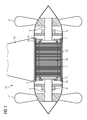
- FIG. 1 shows a POD drive 10, also called nacelle drive.
- the electric nacelle drive 10 is to be fastened by means of a shaft 18 to the hull of a ship and has to drive the ship propeller 17.
- the drive power is applied by an electric motor having a hollow cylindrical stator with a stator lamination stack 1 and a rotatably mounted rotor 16 in the stator, the rotor 16 is rotatably connected by means of a shaft 6 with the propellers 17.
- the stator is enclosed by a housing part 12 in the circumferential direction, which extends in the axial direction along the length of the stator.
- cooling channels 13 are provided, which extend in the axial direction and in which a cooling medium can flow for cooling the electric motor.
- the cooling channels 13 are bounded radially inward by a respective layer 14 of a material which has a thermal conductivity of at least 1 W / (m * K) and which is resistant to corrosion at least in a seawater-containing atmosphere.
- the stator has, in addition to the laminated stator core 1, windings with winding heads 7, which protrude from the stator lamination stack 1.
- the rotor 16 is mounted on bearings 8.
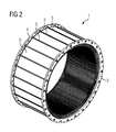
- FIG. 2 shows a first laminated stator core 1 with end (ie frontal) pressure plates 2 and 4. Between the printing plates 2 and 4 is a plurality of juxtaposed electric plates 5. The printing plates 2 and 4 are connected to each other via bolt 3. The pressure plates 2 and 4 are interconnected via the latches 3 such that the pressure plates 2 and 4 exert a force on the layered electric plates 5 such that they are compressed. The bars 3 are uniformly distributed over the circumference of the laminated stator core 1 and aligned parallel to each other. The bolt 3 take a right angle to the pressure plate 2 and 4, respectively.
- FIG. 3 shows a second stator lamination stack 1 with end-side pressure plates 2 and 4. Between the pressure plates 2 and 4 is a plurality of juxtaposed electric plates 5. The pressure plates 2 and 4 are connected to each other via bolt 3. Furthermore, the stator lamination stack 1 is inferior FIG. 3 also intermediate plates 9, which may also be referred to as intermediate printing plates. The intermediate plates can distribute pressure forces within the laminated core, for example. Furthermore, it is possible to connect the latch 3 with the intermediate plates 9. The connection is for example a welded connection. In one embodiment, where bolt 3 and intermediate plates 9 intersect, all bolts 3 are connected to the intermediate plates 9, in particular welded.
- the stator laminated core 1 after FIG. 3 has a first zone 21 and a second zone 22.
- the bolt 3, the intermediate plates 9 and the pressure plate 4 are raised, so they extend beyond the electric plates 5 also.
- the bars 3, the intermediate plates 9 and the pressure plate 2 not sublime, so they do not extend beyond the electric plates 5 addition.
- bars 3, electric plates 5 and pressure plate 2 form the same circumferential radius. This is achieved by subjecting the second zone 22 to a turning operation.
- Pressure plate 2, 3 bars and intermediate plates 9 are turned off in the second zone 22 and form a cylindrical surface.
- only the pressure plates can be turned off the bolts and the intermediate plates, wherein the electric plates 5 are not turned off. Printing plates and bars, and possibly the intermediate plates are then turned off on the circumference of the electric plates 5.
- the laminated stator core 1 also shows an embodiment in which the distance 54 between the latches 3 in the circumferential direction is smaller than the distance 55 between the intermediate plates 9 relative to one another in the axial direction.
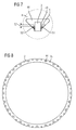
- FIG. 4 shows a front side of a stator lamination stack 1. Shown are teeth 23 and intermediate grooves 24 for stator windings.
- the pressure plate 4 has holes 44 into which bars 3 protrude. The bars 3 are welded to the pressure plate 4.
- the height 41 of the teeth 23 is approximately equal to the height 42 of the pressure plate 4 and the height of the yoke.
- the ends of the teeth 23 form an inner diameter 26.
- the pressure plate has an outer diameter 28 and an inner diameter 27. From the difference between the outer diameter 28 of the pressure plate 4 and the inner diameter 27 of the pressure plate 4 results in the height of the pressure plate 4, ie the height 42 of the formed pressure ring 4.
- clamping holes 25th Clamping devices such as tie rods can be inserted.
- the tension rods between the pressure plates of a laminated stator core By means of the tension rods between the pressure plates of a laminated stator core, this can be clamped together. Thereafter, the latch 3 can be welded to the pressure plates at both ends of the stator lamination stack. After this, the tension rods can be removed again. Are the latch 3 attached to the printing plates so the height of the pressure plate 4 can be reduced. This is done in particular by reducing the outer diameter 28. The outer diameter 28 can be reduced by a turning or by a milling. As a result, the yoke height 43 can be adjusted. After processing, the pressure plate has an outer diameter 29. This results in a reduced radius 30 for the laminated stator core.
- FIG. 5 shows a longitudinal section according to the sectional plane V in FIG. 4
- FIG. 5 additionally shows the packed electrical sheets 5 and end webs 46. Between the web plates 46 and the pressure plates 2 and 4 are pressure fingers 45 for transmitting the forces. The bars 3 protrude through the holes 44 of the printing plates 2 and 4, respectively.
- FIG. 6 shows a cross section through the stator lamination stack 1 in a region of a bolt 3.
- the cut results from the sectional plane VI after FIG. 5 ,
- the electric sheets 5 have a locking groove 48 in which the bolt 3 is inserted.
- the locking groove 48 is wider than the bolt 3, so that lateral distances 49 form.
- a hard mat for positioning can be inserted.
- the hard mat may for example extend from the groove bottom to the end of the groove or end before.
- the hard mat can be in the groove on either side of the latch, or just one.
- the hard mat can also be in the groove base, so that the latch rests on the hard mat.
- the region 50 or even the region 56 is removed, with the result that the latch 50 no longer projects beyond the electrical metal sheet 5.
- FIG. 7 shows a section VII after FIG. 4 , Shown is a trapezoidal hole 44 in the pressure plate 4, wherein in the groove 48 for the bolt 3, the bolt is fitted.
- the bolt 3 is welded on both sides in the groove 48 with the pressure plate 4.
- the bolt or bars are welded in one embodiment only with the pressure plates and the intermediate plates and not with the electric sheets or only partially with the electric sheets.
- the But bars can also be welded over the entire length with the laminated core.
- the final outer diameter of the laminated stator core is located in a region 57. This shows that the welds 51, 52 are not or only slightly reduced.
- FIG. 8 shows the pressure plate 2 separated.
- the holes 44 as well as the clamping holes 25 are distributed symmetrically over the circumference. Due to the symmetrical distribution of the clamping holes, a symmetrical distribution of the clamping forces is achieved during production. Due to the symmetrical distribution of the holes 44 for the bolt 3, a symmetrical distribution of the clamping forces in the finished laminated stator core succeeds.
Priority Applications (4)
| Application Number | Priority Date | Filing Date | Title |
|---|---|---|---|
| EP15185695.2A EP3145055A1 (fr) | 2015-09-17 | 2015-09-17 | Paquet de tole de stator et son procede de fabrication |
| PCT/EP2016/069379 WO2017045852A1 (fr) | 2015-09-17 | 2016-08-16 | Paquet de tôles de stator et procédé de fabrication |
| CN201680051200.7A CN107925280A (zh) | 2015-09-17 | 2016-08-16 | 定子叠片组及其制造方法 |
| EP16757589.3A EP3326265B1 (fr) | 2015-09-17 | 2016-08-16 | Paquet de tole de stator et son procede de fabrication |
Applications Claiming Priority (1)
| Application Number | Priority Date | Filing Date | Title |
|---|---|---|---|
| EP15185695.2A EP3145055A1 (fr) | 2015-09-17 | 2015-09-17 | Paquet de tole de stator et son procede de fabrication |
Publications (1)
| Publication Number | Publication Date |
|---|---|
| EP3145055A1 true EP3145055A1 (fr) | 2017-03-22 |
Family
ID=54148432
Family Applications (2)
| Application Number | Title | Priority Date | Filing Date |
|---|---|---|---|
| EP15185695.2A Withdrawn EP3145055A1 (fr) | 2015-09-17 | 2015-09-17 | Paquet de tole de stator et son procede de fabrication |
| EP16757589.3A Active EP3326265B1 (fr) | 2015-09-17 | 2016-08-16 | Paquet de tole de stator et son procede de fabrication |
Family Applications After (1)
| Application Number | Title | Priority Date | Filing Date |
|---|---|---|---|
| EP16757589.3A Active EP3326265B1 (fr) | 2015-09-17 | 2016-08-16 | Paquet de tole de stator et son procede de fabrication |
Country Status (3)
| Country | Link |
|---|---|
| EP (2) | EP3145055A1 (fr) |
| CN (1) | CN107925280A (fr) |
| WO (1) | WO2017045852A1 (fr) |
Cited By (1)
| Publication number | Priority date | Publication date | Assignee | Title |
|---|---|---|---|---|
| EP3490105A1 (fr) | 2017-11-24 | 2019-05-29 | Siemens Aktiengesellschaft | Stator pour une machine rotative électrique |
Citations (8)
| Publication number | Priority date | Publication date | Assignee | Title |
|---|---|---|---|---|
| DE877254C (de) | 1949-11-29 | 1955-01-31 | Pleuger K G | Elektromotorische Antriebsvorrichtung fuer Propeller od. dgl. von Schiffen |
| US4227109A (en) * | 1978-11-30 | 1980-10-07 | Westinghouse Electric Corp. | System for providing uniform axial expansion of a stator core |
| US4485320A (en) * | 1981-09-08 | 1984-11-27 | Fanuc Ltd. | Welded stator using non-magnetic bars in specially shaped lamination slots |
| EP0171571A1 (fr) * | 1984-08-09 | 1986-02-19 | BBC Brown Boveri AG | Corps de stator à plaques de pression lamellées |
| EP1026814A2 (fr) * | 1999-02-04 | 2000-08-09 | Siemens Westinghouse Power Corporation | Procédé pour l'assemblage d'un stator sur place |
| DE102006025395A1 (de) * | 2005-06-10 | 2006-12-14 | Denso Corp., Kariya | Rotierende elektrische Maschine, die mit einem Statorkern ausgerüstet ist, um die Leistungsfähigkeit der Maschine sicherzustellen |
| US20090026877A1 (en) * | 2007-07-27 | 2009-01-29 | Alfermann Timothy J | Stir-welded rotors and methods of making |
| US20110101819A1 (en) * | 2009-11-04 | 2011-05-05 | Ming-Hung Hsieh | Fixing enhancement mechanism for large iron core |
Family Cites Families (4)
| Publication number | Priority date | Publication date | Assignee | Title |
|---|---|---|---|---|
| CN2760844Y (zh) * | 2004-12-08 | 2006-02-22 | 中国北车集团永济电机厂 | 全叠片电机机座 |
| CN201181859Y (zh) * | 2008-03-14 | 2009-01-14 | 天津市天发重型水电设备制造有限公司 | 一种发电机定子铁芯的小齿压板结构 |
| CN201365177Y (zh) * | 2009-03-06 | 2009-12-16 | 无锡哈电电机有限公司 | 中小型汽轮发电机定子铁心的外装压结构 |
| CN201918807U (zh) * | 2010-06-18 | 2011-08-03 | 中国船舶重工集团公司第七一二研究所 | 一种感应推进电动机 |
-
2015
- 2015-09-17 EP EP15185695.2A patent/EP3145055A1/fr not_active Withdrawn
-
2016
- 2016-08-16 CN CN201680051200.7A patent/CN107925280A/zh active Pending
- 2016-08-16 WO PCT/EP2016/069379 patent/WO2017045852A1/fr active Application Filing
- 2016-08-16 EP EP16757589.3A patent/EP3326265B1/fr active Active
Patent Citations (8)
| Publication number | Priority date | Publication date | Assignee | Title |
|---|---|---|---|---|
| DE877254C (de) | 1949-11-29 | 1955-01-31 | Pleuger K G | Elektromotorische Antriebsvorrichtung fuer Propeller od. dgl. von Schiffen |
| US4227109A (en) * | 1978-11-30 | 1980-10-07 | Westinghouse Electric Corp. | System for providing uniform axial expansion of a stator core |
| US4485320A (en) * | 1981-09-08 | 1984-11-27 | Fanuc Ltd. | Welded stator using non-magnetic bars in specially shaped lamination slots |
| EP0171571A1 (fr) * | 1984-08-09 | 1986-02-19 | BBC Brown Boveri AG | Corps de stator à plaques de pression lamellées |
| EP1026814A2 (fr) * | 1999-02-04 | 2000-08-09 | Siemens Westinghouse Power Corporation | Procédé pour l'assemblage d'un stator sur place |
| DE102006025395A1 (de) * | 2005-06-10 | 2006-12-14 | Denso Corp., Kariya | Rotierende elektrische Maschine, die mit einem Statorkern ausgerüstet ist, um die Leistungsfähigkeit der Maschine sicherzustellen |
| US20090026877A1 (en) * | 2007-07-27 | 2009-01-29 | Alfermann Timothy J | Stir-welded rotors and methods of making |
| US20110101819A1 (en) * | 2009-11-04 | 2011-05-05 | Ming-Hung Hsieh | Fixing enhancement mechanism for large iron core |
Cited By (1)
| Publication number | Priority date | Publication date | Assignee | Title |
|---|---|---|---|---|
| EP3490105A1 (fr) | 2017-11-24 | 2019-05-29 | Siemens Aktiengesellschaft | Stator pour une machine rotative électrique |
Also Published As
| Publication number | Publication date |
|---|---|
| EP3326265B1 (fr) | 2020-02-12 |
| EP3326265A1 (fr) | 2018-05-30 |
| WO2017045852A1 (fr) | 2017-03-23 |
| CN107925280A (zh) | 2018-04-17 |
Similar Documents
| Publication | Publication Date | Title |
|---|---|---|
| EP3289669B1 (fr) | Machine électrique sans boîtier | |
| EP3586427B1 (fr) | Moteur électrique, rotor intérieur et tôle de rotor | |
| WO2016020363A1 (fr) | Rotor, machine à réluctance et procédé de fabrication d'un rotor | |
| DE112014006539T5 (de) | Rotor für einen Käfigläufer-Motor und Käfigläufer-Motor | |
| EP2965403B1 (fr) | Rotor pour moteur à réluctance, procédé de fabrication d'un rotor pour moteur à réluctance, et machine électrique, en particulier moteur à réluctance | |
| DE102012110157A1 (de) | Rotor für einen Asynchronmotor | |
| DE102009057782A1 (de) | Stator für rotierende elektrische Maschine | |
| DE112014004639T5 (de) | Drehende elektrische Maschine und Herstellungsverfahren für diese | |
| EP2850719B1 (fr) | Ensemble stator pour machine electrique | |
| DE102015223058A1 (de) | Käfigläufer und Verfahren für dessen Herstellung | |
| DE102012110147A1 (de) | Rotor für einen Asynchronmotor in gebauter Ausführung | |
| CH710175A2 (de) | Kompressionsbanddistanzpack für einen Statorkern, ein betreffender Stator und Generator. | |
| CH632877A5 (de) | Lamellierter pol fuer eine elektrische maschine mit ausgepraegten polen. | |
| EP2885858B1 (fr) | Rotor à cage d'écureuil pour machine électrique | |
| EP3326265B1 (fr) | Paquet de tole de stator et son procede de fabrication | |
| WO2016078792A2 (fr) | Procédé de fabrication d'un rotor à cage d'écureuil | |
| EP0412954B1 (fr) | Flasque-palier pour un moteur électrique | |
| EP4348809A1 (fr) | Stator pour une machine électrique, machine électrique, système de refroidissement de stator et procédé de refroidissement d'un stator | |
| DE102019130129B3 (de) | Elektromotor für ein Kraftfahrzeug mit einem Innenrotor und einem Außenrotor und einer I-förmigen Tragstruktur, sowie Kraftfahrzeug | |
| CH665063A5 (de) | Asynchronlaeufer. | |
| DE3308006A1 (de) | Rotierende elektromaschine mit luftspaltwicklung | |
| WO2012089404A2 (fr) | Dent d'enroulement pour une machine électrique, composants de machine et machine électrique | |
| DE102020123862A1 (de) | Rotor für einen Elektromotor, entsprechender Elektromotor und Herstellungsverfahren | |
| DE102019205639B3 (de) | Verfahren zur Herstellung eines Blechpakets eines Rotors | |
| DE307451C (fr) |
Legal Events
| Date | Code | Title | Description |
|---|---|---|---|
| PUAI | Public reference made under article 153(3) epc to a published international application that has entered the european phase |
Free format text: ORIGINAL CODE: 0009012 |
|
| AK | Designated contracting states |
Kind code of ref document: A1 Designated state(s): AL AT BE BG CH CY CZ DE DK EE ES FI FR GB GR HR HU IE IS IT LI LT LU LV MC MK MT NL NO PL PT RO RS SE SI SK SM TR |
|
| AX | Request for extension of the european patent |
Extension state: BA ME |
|
| RAP1 | Party data changed (applicant data changed or rights of an application transferred) |
Owner name: SIEMENS AKTIENGESELLSCHAFT |
|
| STAA | Information on the status of an ep patent application or granted ep patent |
Free format text: STATUS: THE APPLICATION IS DEEMED TO BE WITHDRAWN |
|
| 18D | Application deemed to be withdrawn |
Effective date: 20170923 |