EP3145055A1 - Laminated stator sheet package and manufacturing method - Google Patents
Laminated stator sheet package and manufacturing method Download PDFInfo
- Publication number
- EP3145055A1 EP3145055A1 EP15185695.2A EP15185695A EP3145055A1 EP 3145055 A1 EP3145055 A1 EP 3145055A1 EP 15185695 A EP15185695 A EP 15185695A EP 3145055 A1 EP3145055 A1 EP 3145055A1
- Authority
- EP
- European Patent Office
- Prior art keywords
- stator
- plates
- pressure plates
- laminated core
- laminated
- Prior art date
- Legal status (The legal status is an assumption and is not a legal conclusion. Google has not performed a legal analysis and makes no representation as to the accuracy of the status listed.)
- Withdrawn
Links
Images


Classifications
-
- H—ELECTRICITY
- H02—GENERATION; CONVERSION OR DISTRIBUTION OF ELECTRIC POWER
- H02K—DYNAMO-ELECTRIC MACHINES
- H02K1/00—Details of the magnetic circuit
- H02K1/06—Details of the magnetic circuit characterised by the shape, form or construction
- H02K1/12—Stationary parts of the magnetic circuit
- H02K1/16—Stator cores with slots for windings
-
- H—ELECTRICITY
- H02—GENERATION; CONVERSION OR DISTRIBUTION OF ELECTRIC POWER
- H02K—DYNAMO-ELECTRIC MACHINES
- H02K15/00—Methods or apparatus specially adapted for manufacturing, assembling, maintaining or repairing of dynamo-electric machines
- H02K15/02—Methods or apparatus specially adapted for manufacturing, assembling, maintaining or repairing of dynamo-electric machines of stator or rotor bodies
- H02K15/024—Methods or apparatus specially adapted for manufacturing, assembling, maintaining or repairing of dynamo-electric machines of stator or rotor bodies with slots
Definitions
- the invention relates to a laminated stator core of an electrical machine, which can be used in particular in a POD drive of a ship.
- the laminated stator core has a multiplicity of metal sheets. By means of the plates grooves are formed, which are provided for stator windings.
- the stator lamination stack may be provided for an electrical machine, which is, for example, an asynchronous machine or a synchronous machine.
- the electric machine can be operated as a motor or as a generator. Depending on the field of application of the electrical machine, a wide variety of requirements can be made of these. For example, one requirement is that of high rigidity. The stiffness of the electric machine can also affect the rigidity of the stator lamination stack. Another requirement for the electrical machine or the laminated stator core is, for example, a compact construction.
- the nacelle drive is used, for example, as a drive unit in a ship, with the nacelle drive outside the hull and below the water level, especially in seawater, and drives a propeller.
- pod drives are also known as POD drives.
- Rotary electrical machines are used, for example, in the area of ships, for example for so-called rudder propellers (POD drives).
- POD drives rudder propellers
- a nacelle drive which has an electric motor in a motor housing, wherein the motor housing is enclosed by the nacelle housing.
- An object of the invention is to meet various requirements of the type described above in a laminated stator core.
- the invention and the object relate not only to a laminated stator core, but also to an electrical machine, to a method for producing the electrical machine and to the use of the electric machine, in particular as a POD drive.
- a laminated stator core has pressure plates on its end.
- the pressure plate may be annular or disc-shaped.
- An annular pressure plate may also be referred to as a pressure ring.
- Each end face is provided at least one pressure plate.
- the end pressure plates are interconnected by a plurality of bars.
- the bars are for example flat bars, flat strips or round bars.
- the bars in particular run essentially axially parallel.
- the bolts allow axial clamping forces to be exerted on the laminated core.
- the bolts can replace or supplement internal or external clamping bolts.
- the clamping bolts serve to exert axial clamping forces.
- the printing plate can be designed differently.
- the pressure plate can be in one piece or in several parts.
- the pressure plate may be made of a solid material, or also of a composite of a plurality of interconnected electric sheets, or spoke-shaped, or have a different shape.
- the bars increase the rigidity of the laminated core.
- the laminated core whose rigidity is additionally increased by baked enamel, ie by a baked enamel treatment of the laminated core.
- a high rigidity of the laminated core and thus also of the stator of the electric machine enables a slim design of the stator. This can be advantageous, for example, in the case of POD drives for ships, since a better flow behavior of the POD (nacelle drive) can thus be achieved.
- POD nacelle drive
- the rigidity of the laminated core can be achieved, for example, by a large yoke height or by another length-diameter ratio.
- the use of the bars can mean a slightly higher material overhead, but can be compensated by the optimized manufacturing process.
- the latches are at least partially located in grooves of the laminated core, that is to say in slots of electrical lamination.
- the bars can be sunk in the grooves completely or partially.
- the grooves for the latches are to be distinguished from the grooves for the windings.
- the grooves for the windings are inside, so are directed with their openings to the axis.
- the grooves for the bolt distributed over the circumference outside, so with their openings directed radially outward.
- the bars and pressure plates not only the rigidity can be improved, but also the heat dissipation, since the bars are at least partially integrated into the yoke of the laminated core.
- the slender design reduces the thermal resistance as the possible lower yoke height. At the same time, material costs can also be reduced through material savings.
- the bolts are welded to the end-side pressure plates. By welding, a very durable connection between bolt and pressure plate can be produced.
- the rigidity is increased by flat bars.
- flat bars are arranged on the outer diameter, which are welded to the pressure plates.
- the cross-section of the flat bars is chosen so large that the necessary rigidity of the entire laminated stator core is achieved. With comparatively little effort, the necessary rigidity in the laminated core can be generated and at the same time a sleek design can be achieved.
- a hydrodynamically favorable machine cross section can be achieved, so that in the end direct fuel or operating costs are saved.
- this has at least one intermediate plate between the respective end-side pressure plates. Also through the intermediate plate pressure can be distributed.
- the intermediate plate can thus also be referred to as an intermediate pressure plate.
- the bars are welded to the intermediate plate or to a plurality of intermediate plates. This contributes to increasing the rigidity.
- the intermediate plates are for example distributed symmetrically in the laminated core.
- the bars can be distributed symmetrically over the circumference of the laminated core.
- the bolts are at least partially guided by the end-side pressure plates. This facilitates a welded connection between the latch and the pressure plate.
- the end-side pressure plates are turned off and / or beveled. By turning off a more compact design is achieved.
- the laminated stator core is turned off. This also serves a more compact design.
- this has teeth, wherein the windings are to be positioned between the teeth, the tooth height being greater than the height of the end-side pressure plate. Also, you can reduce the diameter.
- the height of the yoke does not exceed 1.5 times the tooth height.
- the yoke height is thus at most 150% of the tooth height. So while the diameter is increased, but also the stability of the higher yoke.
- the tooth height is greater than the height of the yoke.
- the yoke is so high that it can still carry enough flow. If enough flow can be made, the stator plate can be designed in such a way that the height of the yoke is at most 80% of the tooth height.
- the diameter of the laminated stator core can be reduced with a comparatively long length. Often, a larger diameter, a shorter length and / or a larger yoke height would otherwise be necessary.
- the individual sheet metal layers are often axially clamped in conventional laminated cores only by chip pin, which are located within the laminated core. Additional rigidity is sometimes applied during manufacture by a device which is removed after the manufacturing steps.
- the spacing of the bars in the circumferential direction is smaller than the spacing of the intermediate plates in the axial direction. This makes it possible to achieve a particularly high rigidity.
- the laminated stator core In one embodiment of the laminated stator core, this is intended for a nacelle drive. Due to the small diameter, the cross section of the nacelle can be kept small. This is also possible in particular because the laminated stator core already has a high rigidity and the rigidity of the housing of the nacelle is not to be interpreted as excessive. The rigidity of the laminated stator core can also be increased by virtue of the fact that, as soon as the winding is inserted in the stator laminated core, the stator yoke is impregnated in order to achieve a high final rigidity.
- end plates are welded to bars.
- the laminated stator core is turned off to reduce its circumference. For example, protruding material of the flat bars and printing plates is turned off. That's why one can also speak of a lost device here.
- the end-side pressure plate is turned off or milled. In this way, the length of the laminated stator core can be reduced.
- the stator lamination packet is reduced in diameter so that it can be introduced into a nacelle.
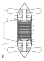
- FIG. 1 shows a POD drive 10, also called nacelle drive.
- the electric nacelle drive 10 is to be fastened by means of a shaft 18 to the hull of a ship and has to drive the ship propeller 17.
- the drive power is applied by an electric motor having a hollow cylindrical stator with a stator lamination stack 1 and a rotatably mounted rotor 16 in the stator, the rotor 16 is rotatably connected by means of a shaft 6 with the propellers 17.
- the stator is enclosed by a housing part 12 in the circumferential direction, which extends in the axial direction along the length of the stator.
- cooling channels 13 are provided, which extend in the axial direction and in which a cooling medium can flow for cooling the electric motor.
- the cooling channels 13 are bounded radially inward by a respective layer 14 of a material which has a thermal conductivity of at least 1 W / (m * K) and which is resistant to corrosion at least in a seawater-containing atmosphere.
- the stator has, in addition to the laminated stator core 1, windings with winding heads 7, which protrude from the stator lamination stack 1.
- the rotor 16 is mounted on bearings 8.
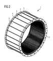
- FIG. 2 shows a first laminated stator core 1 with end (ie frontal) pressure plates 2 and 4. Between the printing plates 2 and 4 is a plurality of juxtaposed electric plates 5. The printing plates 2 and 4 are connected to each other via bolt 3. The pressure plates 2 and 4 are interconnected via the latches 3 such that the pressure plates 2 and 4 exert a force on the layered electric plates 5 such that they are compressed. The bars 3 are uniformly distributed over the circumference of the laminated stator core 1 and aligned parallel to each other. The bolt 3 take a right angle to the pressure plate 2 and 4, respectively.
- FIG. 3 shows a second stator lamination stack 1 with end-side pressure plates 2 and 4. Between the pressure plates 2 and 4 is a plurality of juxtaposed electric plates 5. The pressure plates 2 and 4 are connected to each other via bolt 3. Furthermore, the stator lamination stack 1 is inferior FIG. 3 also intermediate plates 9, which may also be referred to as intermediate printing plates. The intermediate plates can distribute pressure forces within the laminated core, for example. Furthermore, it is possible to connect the latch 3 with the intermediate plates 9. The connection is for example a welded connection. In one embodiment, where bolt 3 and intermediate plates 9 intersect, all bolts 3 are connected to the intermediate plates 9, in particular welded.
- the stator laminated core 1 after FIG. 3 has a first zone 21 and a second zone 22.
- the bolt 3, the intermediate plates 9 and the pressure plate 4 are raised, so they extend beyond the electric plates 5 also.
- the bars 3, the intermediate plates 9 and the pressure plate 2 not sublime, so they do not extend beyond the electric plates 5 addition.
- bars 3, electric plates 5 and pressure plate 2 form the same circumferential radius. This is achieved by subjecting the second zone 22 to a turning operation.
- Pressure plate 2, 3 bars and intermediate plates 9 are turned off in the second zone 22 and form a cylindrical surface.
- only the pressure plates can be turned off the bolts and the intermediate plates, wherein the electric plates 5 are not turned off. Printing plates and bars, and possibly the intermediate plates are then turned off on the circumference of the electric plates 5.
- the laminated stator core 1 also shows an embodiment in which the distance 54 between the latches 3 in the circumferential direction is smaller than the distance 55 between the intermediate plates 9 relative to one another in the axial direction.
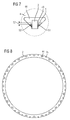
- FIG. 4 shows a front side of a stator lamination stack 1. Shown are teeth 23 and intermediate grooves 24 for stator windings.
- the pressure plate 4 has holes 44 into which bars 3 protrude. The bars 3 are welded to the pressure plate 4.
- the height 41 of the teeth 23 is approximately equal to the height 42 of the pressure plate 4 and the height of the yoke.
- the ends of the teeth 23 form an inner diameter 26.
- the pressure plate has an outer diameter 28 and an inner diameter 27. From the difference between the outer diameter 28 of the pressure plate 4 and the inner diameter 27 of the pressure plate 4 results in the height of the pressure plate 4, ie the height 42 of the formed pressure ring 4.
- clamping holes 25th Clamping devices such as tie rods can be inserted.
- the tension rods between the pressure plates of a laminated stator core By means of the tension rods between the pressure plates of a laminated stator core, this can be clamped together. Thereafter, the latch 3 can be welded to the pressure plates at both ends of the stator lamination stack. After this, the tension rods can be removed again. Are the latch 3 attached to the printing plates so the height of the pressure plate 4 can be reduced. This is done in particular by reducing the outer diameter 28. The outer diameter 28 can be reduced by a turning or by a milling. As a result, the yoke height 43 can be adjusted. After processing, the pressure plate has an outer diameter 29. This results in a reduced radius 30 for the laminated stator core.
- FIG. 5 shows a longitudinal section according to the sectional plane V in FIG. 4
- FIG. 5 additionally shows the packed electrical sheets 5 and end webs 46. Between the web plates 46 and the pressure plates 2 and 4 are pressure fingers 45 for transmitting the forces. The bars 3 protrude through the holes 44 of the printing plates 2 and 4, respectively.
- FIG. 6 shows a cross section through the stator lamination stack 1 in a region of a bolt 3.
- the cut results from the sectional plane VI after FIG. 5 ,
- the electric sheets 5 have a locking groove 48 in which the bolt 3 is inserted.
- the locking groove 48 is wider than the bolt 3, so that lateral distances 49 form.
- a hard mat for positioning can be inserted.
- the hard mat may for example extend from the groove bottom to the end of the groove or end before.
- the hard mat can be in the groove on either side of the latch, or just one.
- the hard mat can also be in the groove base, so that the latch rests on the hard mat.
- the region 50 or even the region 56 is removed, with the result that the latch 50 no longer projects beyond the electrical metal sheet 5.
- FIG. 7 shows a section VII after FIG. 4 , Shown is a trapezoidal hole 44 in the pressure plate 4, wherein in the groove 48 for the bolt 3, the bolt is fitted.
- the bolt 3 is welded on both sides in the groove 48 with the pressure plate 4.
- the bolt or bars are welded in one embodiment only with the pressure plates and the intermediate plates and not with the electric sheets or only partially with the electric sheets.
- the But bars can also be welded over the entire length with the laminated core.
- the final outer diameter of the laminated stator core is located in a region 57. This shows that the welds 51, 52 are not or only slightly reduced.
- FIG. 8 shows the pressure plate 2 separated.
- the holes 44 as well as the clamping holes 25 are distributed symmetrically over the circumference. Due to the symmetrical distribution of the clamping holes, a symmetrical distribution of the clamping forces is achieved during production. Due to the symmetrical distribution of the holes 44 for the bolt 3, a symmetrical distribution of the clamping forces in the finished laminated stator core succeeds.
Abstract
Ein Statorblechpaket (1) weist Druckplatten (2,4) auf, wobei eine Vielzahl von Riegel (3) die zumindest zwei Druckplatten (2,4) miteinander verbinden, wobei die Druckplatten (2,4) insbesondere endseitige Druckplatten (2,4) sind. Die Riegel (3) sind zumindest teilweise in den Nuten (48) von Elektroblechen. Die Riegel (3) werden mit den Druckplatten (2,4) verschweißt. Das Statorblechpaket eignet sich insbesondere für einen Pod-Antrieb.A stator lamination stack (1) has pressure plates (2, 4), wherein a multiplicity of latches (3) connect the at least two pressure plates (2, 4), the pressure plates (2, 4) in particular end-side pressure plates (2, 4). are. The latches (3) are at least partially in the grooves (48) of electrical sheets. The bars (3) are welded to the pressure plates (2,4). The laminated stator core is particularly suitable for a pod drive.
Description
Die Erfindung betrifft ein Statorblechpaket einer elektrischen Maschine, welche insbesondere in einem POD-Antrieb eines Schiffes einsetzbar ist.The invention relates to a laminated stator core of an electrical machine, which can be used in particular in a POD drive of a ship.
Das Statorblechpaket weist eine Vielzahl von Blechen auf. Mittels der Bleche werden Nuten ausgebildet, welche für Statorwicklungen vorgesehen sind. Das Statorblechpaket kann für eine elektrische Maschine vorgesehen sein, welche beispielsweise eine Asynchronmaschine oder eine Synchronmaschine ist. Die elektrische Maschine kann als Motor oder als Generator betrieben werden. Abhängig vom Einsatzgebiet der elektrischen Maschine können an diese verschiedenste Anforderungen gestellt werden. Eine Anforderung ist beispielsweise die einer hohen Steifigkeit. Dabei kann die Steifigkeit der elektrischen Maschine auch die Steifigkeit des Statorblechpaketes betreffen. Eine weitere Anforderung an die elektrische Maschine oder an das Statorblechpaket ist beispielsweise ein kompakter Aufbau.The laminated stator core has a multiplicity of metal sheets. By means of the plates grooves are formed, which are provided for stator windings. The stator lamination stack may be provided for an electrical machine, which is, for example, an asynchronous machine or a synchronous machine. The electric machine can be operated as a motor or as a generator. Depending on the field of application of the electrical machine, a wide variety of requirements can be made of these. For example, one requirement is that of high rigidity. The stiffness of the electric machine can also affect the rigidity of the stator lamination stack. Another requirement for the electrical machine or the laminated stator core is, for example, a compact construction.
Der Gondelantrieb kommt beispielsweise als Antriebseinheit bei einem Schiff zum Einsatz, wobei sich der Gondelantrieb außerhalb des Schiffsrumpfes und unterhalb des Wasserspiegels, insbesondere im Meerwasser, befindet und einen Propeller antreibt. Derartige Gondelantriebe sind auch unter der Bezeichnung POD-Antriebe bekannt. Rotierende elektrische Maschinen werden beispielsweise im Schiffsbereich u.a. für sogenannten Ruderpropeller (POD-Antriebe) eingesetzt. An die Statorbaugruppe für den Schiffsantrieb können dabei verschiedene Anforderungen gestellt werden wie z.B. ein geringer Außendurchmesser für ein vorteilhaftes hydrodynamische Verhalten der Gesamtmaschine oder ein großer Innendurchmesser, sowie eine große Aktivteillänge zur Erzeugung des Drehmoments. Hieraus ergibt sich für das Gesamtdesign des Stators eines POD-Antriebes in einer groben Abstraktion ein "langes dünnwandiges Rohr". Hieraus kann sich für das Statorblechpaket eine geringere Steifigkeit als bei herkömmlichen Statorblechpaketen ergeben.The nacelle drive is used, for example, as a drive unit in a ship, with the nacelle drive outside the hull and below the water level, especially in seawater, and drives a propeller. Such pod drives are also known as POD drives. Rotary electrical machines are used, for example, in the area of ships, for example for so-called rudder propellers (POD drives). To the stator assembly for the marine propulsion while various requirements can be made such as a small outer diameter for an advantageous hydrodynamic behavior of the overall machine or a large inner diameter, and a large active part length for generating the torque. This results in a gross thin abstraction for the overall design of the stator of a POD drive a "long thin-walled From this, a lower rigidity than for conventional stator lamination packages can result for the laminated stator core.
Aus der
Eine Aufgabe der Erfindung ist es bei einem Statorblechpaket verschiedene Anforderungen der obig beschriebenen Art zu erfüllen. Dabei betreffen die Erfindung und die Aufgabe nicht nur ein Statorblechpaket, sondern auch eine elektrische Maschine, ein Verfahren zur Herstellung der elektrischen Maschine und die Verwendung der elektrischen Maschine insbesondere als POD-Antrieb.An object of the invention is to meet various requirements of the type described above in a laminated stator core. In this case, the invention and the object relate not only to a laminated stator core, but also to an electrical machine, to a method for producing the electrical machine and to the use of the electric machine, in particular as a POD drive.
Ein Lösung der Aufgabe ergibt sich bei einem Statorblechpaket nach Anspruch 1 und bei einem Verfahren zu dessen Herstellung nach Anspruch 13. Ausgestaltungen der Erfindung ergeben sich nach den Ansprüchen 2 bis 12 bzw. 14 bis 17. Weitere Lösungen ergeben sich bei einer elektrischen Maschine mit dem Statorblechpaket und bei einem POD-Antrieb eines Schiffes mit einer elektrischen Maschine mit dem Statorblechpaket.A solution to the problem arises in a stator lamination according to
Ein Statorblechpaket weist endseitig Druckplatten auf. Die Druckplatte kann ringförmig oder scheibenförmig sein. Eine ringförmige Druckplatte kann auch als Druckringbezeichnet werden. Je Stirnseite ist zumindest eine Druckplatte vorgesehen. Die endseitigen Druckplatten sind durch eine Vielzahl von Riegel miteinander verbunden. Die Riegel sind beispielsweise Flachstäbe, Flachbänder oder Rundstäbe. Die Riegel verlaufen insbesondere im Wesentlichen axial parallel. Durch die Riegel lassen sich axiale Verspannkräfte auf das Blechpaket ausüben. Die Riegel können dabei innenliegende oder außenliegende Spannbolzen ersetzen oder ergänzen. Auch die Spannbolzen dienen der Ausübung von axialen Verspannkräften.A laminated stator core has pressure plates on its end. The pressure plate may be annular or disc-shaped. An annular pressure plate may also be referred to as a pressure ring. Each end face is provided at least one pressure plate. The end pressure plates are interconnected by a plurality of bars. The bars are for example flat bars, flat strips or round bars. The bars in particular run essentially axially parallel. The bolts allow axial clamping forces to be exerted on the laminated core. The bolts can replace or supplement internal or external clamping bolts. The clamping bolts serve to exert axial clamping forces.
Die Druckplatte kann verschieden ausgeführt sein. Die Druckplatte kann einteilig oder mehrteilig sein. Die Druckplatte kann aus einem Vollmaterial sein, oder auch aus einem Verbund mehrerer miteinander verbundener Elektrobleche, oder speichenförmig, oder eine andere Gestalt aufweisen.The printing plate can be designed differently. The pressure plate can be in one piece or in several parts. The pressure plate may be made of a solid material, or also of a composite of a plurality of interconnected electric sheets, or spoke-shaped, or have a different shape.
Durch die Riegel erhöht sich die Steifigkeit des Blechpaketes. In einer weiteren Ausgestaltung des Blechpaketes wird dessen Steifigkeit zusätzlich durch Backlack erhöht, also durch eine Backlackbehandlung des Blechpaketes.The bars increase the rigidity of the laminated core. In a further embodiment of the laminated core whose rigidity is additionally increased by baked enamel, ie by a baked enamel treatment of the laminated core.
Eine hohe Steifigkeit des Blechpaketes und damit auch des Stators der elektrischen Maschine ermöglicht ein schlankes Design des Stators. Dies kann beispielsweise bei POD-Antrieben für Schiffe vorteilhaft sein, da so ein besseres Strömungsverhalten des POD's (Gondelantrieb) realisierbar ist. Durch die Verwendung von Riegel zur Erhöhung der Steifigkeit ist es auch möglich Kosten zu sparen, die sonst für andere umfangreiche Vorrichtungen zu Erhöhung der Steifigkeit des Blechpaketes notwendig wären.A high rigidity of the laminated core and thus also of the stator of the electric machine enables a slim design of the stator. This can be advantageous, for example, in the case of POD drives for ships, since a better flow behavior of the POD (nacelle drive) can thus be achieved. By using bolts to increase rigidity, it is also possible to save costs that would otherwise be necessary for other extensive devices to increase the rigidity of the laminated core.
Die Steifigkeit des Blechpaketes kann weiterhin beispielsweise durch eine große Jochhöhe oder durch ein anderes Länge-Durchmesser-Verhältnis erzielt werden.The rigidity of the laminated core can be achieved, for example, by a large yoke height or by another length-diameter ratio.
Die Verwendung der Riegel kann einen geringfügig höheren Materialmehraufwand bedeuten, der aber durch den optimierten Fertigungsprozess ausgeglichen werden kann.The use of the bars can mean a slightly higher material overhead, but can be compensated by the optimized manufacturing process.
In einer Ausbildung des Statorblechpaketes befinden sich die Riegel zumindest teilweise in Nuten des Blechpaketes also folglich in Nuten von Elektroblechen. Die Riegel können so in die Nuten ganz oder teilweise versenkt werden. Die Nuten für die Riegel sind von den Nuten für die Wicklungen zu unterscheiden. Bei einer als Innenläufer ausgebildeten elektrischen Maschine befinden sich die Nuten für die Wicklungen innen, sind mit ihren Öffnungen also zur Achse gerichtet. Bei einer als Innenläufer ausgebildeten elektrischen Maschine befinden sich die Nuten für die Riegel über den Umfang verteilt außen, also mit ihren Öffnungen radial nach außen gerichtet.In an embodiment of the stator lamination stack, the latches are at least partially located in grooves of the laminated core, that is to say in slots of electrical lamination. The bars can be sunk in the grooves completely or partially. The grooves for the latches are to be distinguished from the grooves for the windings. In an electrical machine designed as an internal rotor, the grooves for the windings are inside, so are directed with their openings to the axis. In an electrical machine designed as an internal rotor the grooves for the bolt distributed over the circumference outside, so with their openings directed radially outward.
Durch die Riegel und Druckplatten kann nicht nur die Steifigkeit verbessert werden, sondern auch die Wärmeabfuhr, da die Riegel zumindest teilweise in das Joch des Blechpaketes integriert sind. Zudem wird durch das schlanke Design, als die mögliche geringere Jochhöhe der Wärmewiderstand reduziert. Gleichzeit können auch Materialkosten durch Materialeinsparungen sinken.By the bars and pressure plates not only the rigidity can be improved, but also the heat dissipation, since the bars are at least partially integrated into the yoke of the laminated core. In addition, the slender design reduces the thermal resistance as the possible lower yoke height. At the same time, material costs can also be reduced through material savings.
In einer Ausgestaltung des Statorblechpaketes sind die Riegel mit den endseitigen Druckplatten verschweißt. Durch das Verschweißen lässt sich eine sehr strapazierfähige Verbindung zwischen Riegel und Druckplatte herstellen.In one embodiment of the laminated stator core, the bolts are welded to the end-side pressure plates. By welding, a very durable connection between bolt and pressure plate can be produced.
In einer Ausgestaltung des Statorblechpaketes erfolgt die Erhöhung der Steifigkeit durch Flachstäbe. Um die Blechlagen des Statorblechpakets axial zu verspannen, sind am Außendurchmesser Flachstäbe angeordnet, die an den Druckplatten verschweißt sind. Dadurch wird das Blechpaket axial verspannt. Der Querschnitt der Flachstäbe wird so groß gewählt, dass die notwendige Steifigkeit des gesamten Statorblechpakets erzielt wird. Mit vergleichsweise wenig Aufwand kann so die notwendige Steifigkeit im Blechpaket erzeugt werden und gleichzeitig ein schlankes Design erzielt werden. Beim Einsatz des Statorblechpaketes in einem Stator einer elektrischen Maschine für einen POD-Antrieb kann so ein hydrodynamisch günstiger Maschinenquerschnitt erzielt werden, damit im Endeffekt direkte Treibstoff-, bzw. Betriebskosten eingespart werden.In one embodiment of the laminated stator core, the rigidity is increased by flat bars. To axially clamp the sheet metal layers of the stator lamination, flat bars are arranged on the outer diameter, which are welded to the pressure plates. As a result, the laminated core is axially braced. The cross-section of the flat bars is chosen so large that the necessary rigidity of the entire laminated stator core is achieved. With comparatively little effort, the necessary rigidity in the laminated core can be generated and at the same time a sleek design can be achieved. When using the laminated stator core in a stator of an electric machine for a POD drive, a hydrodynamically favorable machine cross section can be achieved, so that in the end direct fuel or operating costs are saved.
In einer Ausgestaltung des Statorblechpakets weist dieses zwischen den jeweils endseitigen Druckplatten zumindest eine Zwischenplatte auf. Auch durch die Zwischenplatte kann Druck verteilt werden. Die Zwischenplatte kann somit auch als Zwischendruckplatte bezeichnet werden.In one embodiment of the laminated stator core, this has at least one intermediate plate between the respective end-side pressure plates. Also through the intermediate plate pressure can be distributed. The intermediate plate can thus also be referred to as an intermediate pressure plate.
In einer Ausgestaltung des Statorblechpaketes sind die Riegel mit der Zwischenplatte oder mit einer Vielzahl von Zwischenplatten verschweißt. Dies trägt zur Erhöhung der Steifigkeit bei. Die Zwischenplatten sind beispielsweise symmetrisch im Blechpaket verteilt. Auch die Riegel können symmetrisch über den Umfang des Blechpaketes verteilt sein.In one embodiment of the laminated stator core, the bars are welded to the intermediate plate or to a plurality of intermediate plates. This contributes to increasing the rigidity. The intermediate plates are for example distributed symmetrically in the laminated core. The bars can be distributed symmetrically over the circumference of the laminated core.
In einer Ausgestaltung des Statorblechpaketes sind die Riegel zumindest teilweise durch die endseitigen Druckplatten geführt. Dies erleichtert eine Schweißverbindung zwischen den Riegel und der Druckplatte.In one embodiment of the laminated stator core, the bolts are at least partially guided by the end-side pressure plates. This facilitates a welded connection between the latch and the pressure plate.
In einer Ausgestaltung des Statorblechpaketes sind die endseitigen Druckplatten abgedreht und/oder abgefrässt. Durch das Abdrehen wird eine kompaktere Bauform erzielt.In one embodiment of the laminated stator core, the end-side pressure plates are turned off and / or beveled. By turning off a more compact design is achieved.
In einer Ausgestaltung des Statorblechpaketes ist das Statorblechpaket abgedreht. Auch dies dient einer kompakteren Bauform.In one embodiment of the laminated stator core, the laminated stator core is turned off. This also serves a more compact design.
In einer Ausgestaltung des Statorblechpaketes weist dieses Zähne auf, wobei zwischen den Zähnen die Wicklungen zu positionieren sind, wobei die Zahnhöhe größer ist als die Höhe der endseitigen Druckplatte. Auch somit kann man den Durchmesser reduzieren.In one embodiment of the laminated stator core, this has teeth, wherein the windings are to be positioned between the teeth, the tooth height being greater than the height of the end-side pressure plate. Also, you can reduce the diameter.
In einer Ausgestaltung des Statorblechpaketes übersteigt die Höhe des Jochs das 1,5-fache der Zahnhöhe nicht. Die Jochhöhe beträgt also höchstens 150% der Zahnhöhe. So wird zwar der Durchmesser erhöht, aber auch die Stabilität durch das höhere Joch.In one embodiment of the laminated stator core, the height of the yoke does not exceed 1.5 times the tooth height. The yoke height is thus at most 150% of the tooth height. So while the diameter is increased, but also the stability of the higher yoke.
In einer Ausgestaltung des Statorblechpaketes ist die Zahnhöhe größer als die Höhe des Jochs. Dabei ist das Joch derart hoch auszuführen, dass es noch genügend Fluss führen kann. Kann genügend Fluss geführt werden ist das Statorblech derart ausführbar, dass die Jochhöhe höchstens 80% der Zahnhöhe beträgt.In one embodiment of the laminated stator core, the tooth height is greater than the height of the yoke. The yoke is so high that it can still carry enough flow. If enough flow can be made, the stator plate can be designed in such a way that the height of the yoke is at most 80% of the tooth height.
Durch derartige Maßnahmen lässt sich der Durchmesser des Statorblechpaketes bei vergleichsweise großer Länge reduzieren. Häufig wäre sonst ein größerer Durchmesser, eine geringe Länge und/oder eine größere Jochhöhe notwendig. Die einzelnen Blechlagen werden bei herkömmlichen Blechpaketen häufig nur durch Spanbolzen, die sich innerhalb des Blechpakets befinden, axial verspannt. Eine zusätzliche Steifigkeit wird in manchen Fällen während der Fertigung durch eine Vorrichtung aufgebracht, die nach den Fertigungsschritten aber wieder entfernt wird.By such measures, the diameter of the laminated stator core can be reduced with a comparatively long length. Often, a larger diameter, a shorter length and / or a larger yoke height would otherwise be necessary. The individual sheet metal layers are often axially clamped in conventional laminated cores only by chip pin, which are located within the laminated core. Additional rigidity is sometimes applied during manufacture by a device which is removed after the manufacturing steps.
In einer Ausgestaltung des Statorblechpaketes ist der Abstand der Riegel in Umfangsrichtung kleiner als der Abstand der Zwischenplatten in axialer Richtung. Damit lässt sich eine besonders hohe Steifigkeit erzielen.In one embodiment of the laminated stator core, the spacing of the bars in the circumferential direction is smaller than the spacing of the intermediate plates in the axial direction. This makes it possible to achieve a particularly high rigidity.
In einer Ausgestaltung des Statorblechpaketes ist dieses für einen Gondelantrieb vorgesehen. Durch den geringen Durchmesser kann der Querschnitt der Gondel klein gehalten werden. Dies ist insbesondere auch deswegen möglich da das Statorblechpaket schon eine hohe Steifigkeit hat und die Steifigkeit des Gehäuses der Gondel nicht Übergebühr hoch auszulegen ist. Die Steifigkeit des Statorblechpaketes kann auch dadurch erhöht sein, dass sobald in das Statorblechpaket die Wicklung eingelegt ist das Statorjoch getränkt wird um eine hohe endgültige Steifigkeit zu erreichen.In one embodiment of the laminated stator core, this is intended for a nacelle drive. Due to the small diameter, the cross section of the nacelle can be kept small. This is also possible in particular because the laminated stator core already has a high rigidity and the rigidity of the housing of the nacelle is not to be interpreted as excessive. The rigidity of the laminated stator core can also be increased by virtue of the fact that, as soon as the winding is inserted in the stator laminated core, the stator yoke is impregnated in order to achieve a high final rigidity.
In einem Verfahren zur Herstellung eines Statorblechpaketes werden endseitige Druckplatten mit Riegel verschweißt. Hernach wird das Statorblechpaket abgedreht um dessen Umfang zu reduzieren. So wird beispielsweise überstehendes Material der Flachstäbe und Druckplatten abgedreht. Deswegen kann man hier auch von einer verlorenen Vorrichtung sprechen.In a method for producing a laminated stator core, end plates are welded to bars. Afterwards, the laminated stator core is turned off to reduce its circumference. For example, protruding material of the flat bars and printing plates is turned off. That's why one can also speak of a lost device here.
In einer Ausführung des Verfahrens wird die endseitige Druckplatte abgedreht oder abgefräst. Derart kann die Länge des Statorblechpaketes reduziert werden.In one embodiment of the method, the end-side pressure plate is turned off or milled. In this way, the length of the laminated stator core can be reduced.
In einer Ausführung des Verfahrens wird das Statorblechpaket im Durchmesser so verkleinert, dass es in eine Gondel eingebracht werden kann.In one embodiment of the method, the stator lamination packet is reduced in diameter so that it can be introduced into a nacelle.
Im Folgenden wird die Erfindung anhand der in den Figuren dargestellten Ausführungsbeispiele näher beschrieben und erläutert. Es zeigen:
- FIG 1
- einen POD-Antrieb (Gondelantrieb);
- FIG 2
- ein erstes Statorblechpaket;
- FIG 3
- ein zweites Statorblechpaket;
- FIG 4
- eine Stirnseite eines Statorblechpaketes;
- FIG 5
- einen Längsschnitt durch das Statorblechpaket;
- FIG 6
- einen Querschnitt durch das Statorblechpaket in einem Bereich eines Riegels;
- FIG 7
- einen Ausschnitt aus
FIG 4 und - FIG 8
- eine Druckplatte.
- FIG. 1
- a POD drive (nacelle drive);
- FIG. 2
- a first stator lamination stack;
- FIG. 3
- a second stator lamination stack;
- FIG. 4
- an end face of a stator lamination stack;
- FIG. 5
- a longitudinal section through the stator lamination stack;
- FIG. 6
- a cross section through the stator lamination in a region of a bolt;
- FIG. 7
- a section from
FIG. 4 and - FIG. 8
- a printing plate.
Die Darstellung nach
Die Darstellung nach
Die Darstellung nach
Die Darstellung nach
Die Darstellung nach
Die Darstellung nach
Die Darstellung nach
Die Darstellung nach
Claims (17)
Priority Applications (4)
| Application Number | Priority Date | Filing Date | Title |
|---|---|---|---|
| EP15185695.2A EP3145055A1 (en) | 2015-09-17 | 2015-09-17 | Laminated stator sheet package and manufacturing method |
| EP16757589.3A EP3326265B1 (en) | 2015-09-17 | 2016-08-16 | Laminated stator sheet package and manufacturing method |
| PCT/EP2016/069379 WO2017045852A1 (en) | 2015-09-17 | 2016-08-16 | Stator core and manufacturing method |
| CN201680051200.7A CN107925280A (en) | 2015-09-17 | 2016-08-16 | Stator stack and its manufacture method |
Applications Claiming Priority (1)
| Application Number | Priority Date | Filing Date | Title |
|---|---|---|---|
| EP15185695.2A EP3145055A1 (en) | 2015-09-17 | 2015-09-17 | Laminated stator sheet package and manufacturing method |
Publications (1)
| Publication Number | Publication Date |
|---|---|
| EP3145055A1 true EP3145055A1 (en) | 2017-03-22 |
Family
ID=54148432
Family Applications (2)
| Application Number | Title | Priority Date | Filing Date |
|---|---|---|---|
| EP15185695.2A Withdrawn EP3145055A1 (en) | 2015-09-17 | 2015-09-17 | Laminated stator sheet package and manufacturing method |
| EP16757589.3A Active EP3326265B1 (en) | 2015-09-17 | 2016-08-16 | Laminated stator sheet package and manufacturing method |
Family Applications After (1)
| Application Number | Title | Priority Date | Filing Date |
|---|---|---|---|
| EP16757589.3A Active EP3326265B1 (en) | 2015-09-17 | 2016-08-16 | Laminated stator sheet package and manufacturing method |
Country Status (3)
| Country | Link |
|---|---|
| EP (2) | EP3145055A1 (en) |
| CN (1) | CN107925280A (en) |
| WO (1) | WO2017045852A1 (en) |
Cited By (1)
| Publication number | Priority date | Publication date | Assignee | Title |
|---|---|---|---|---|
| EP3490105A1 (en) | 2017-11-24 | 2019-05-29 | Siemens Aktiengesellschaft | Stator for an electric rotating machine |
Citations (8)
| Publication number | Priority date | Publication date | Assignee | Title |
|---|---|---|---|---|
| DE877254C (en) | 1949-11-29 | 1955-01-31 | Pleuger K G | Electric motor drive device for propellers or the like of ships |
| US4227109A (en) * | 1978-11-30 | 1980-10-07 | Westinghouse Electric Corp. | System for providing uniform axial expansion of a stator core |
| US4485320A (en) * | 1981-09-08 | 1984-11-27 | Fanuc Ltd. | Welded stator using non-magnetic bars in specially shaped lamination slots |
| EP0171571A1 (en) * | 1984-08-09 | 1986-02-19 | BBC Brown Boveri AG | Stator core with laminated pressure plates |
| EP1026814A2 (en) * | 1999-02-04 | 2000-08-09 | Siemens Westinghouse Power Corporation | Method for assembly of a stator in the field |
| DE102006025395A1 (en) * | 2005-06-10 | 2006-12-14 | Denso Corp., Kariya | Rotary electric machine equipped with a stator core to ensure the efficiency of the machine |
| US20090026877A1 (en) * | 2007-07-27 | 2009-01-29 | Alfermann Timothy J | Stir-welded rotors and methods of making |
| US20110101819A1 (en) * | 2009-11-04 | 2011-05-05 | Ming-Hung Hsieh | Fixing enhancement mechanism for large iron core |
Family Cites Families (4)
| Publication number | Priority date | Publication date | Assignee | Title |
|---|---|---|---|---|
| CN2760844Y (en) * | 2004-12-08 | 2006-02-22 | 中国北车集团永济电机厂 | Full-laminated motor frame |
| CN201181859Y (en) * | 2008-03-14 | 2009-01-14 | 天津市天发重型水电设备制造有限公司 | Small tooth pressboard structure of generator stator core |
| CN201365177Y (en) * | 2009-03-06 | 2009-12-16 | 无锡哈电电机有限公司 | Externally laminated pressed structure of small and medium size turbonator stator core |
| CN201918807U (en) * | 2010-06-18 | 2011-08-03 | 中国船舶重工集团公司第七一二研究所 | Induction propulsion motor |
-
2015
- 2015-09-17 EP EP15185695.2A patent/EP3145055A1/en not_active Withdrawn
-
2016
- 2016-08-16 EP EP16757589.3A patent/EP3326265B1/en active Active
- 2016-08-16 WO PCT/EP2016/069379 patent/WO2017045852A1/en active Application Filing
- 2016-08-16 CN CN201680051200.7A patent/CN107925280A/en active Pending
Patent Citations (8)
| Publication number | Priority date | Publication date | Assignee | Title |
|---|---|---|---|---|
| DE877254C (en) | 1949-11-29 | 1955-01-31 | Pleuger K G | Electric motor drive device for propellers or the like of ships |
| US4227109A (en) * | 1978-11-30 | 1980-10-07 | Westinghouse Electric Corp. | System for providing uniform axial expansion of a stator core |
| US4485320A (en) * | 1981-09-08 | 1984-11-27 | Fanuc Ltd. | Welded stator using non-magnetic bars in specially shaped lamination slots |
| EP0171571A1 (en) * | 1984-08-09 | 1986-02-19 | BBC Brown Boveri AG | Stator core with laminated pressure plates |
| EP1026814A2 (en) * | 1999-02-04 | 2000-08-09 | Siemens Westinghouse Power Corporation | Method for assembly of a stator in the field |
| DE102006025395A1 (en) * | 2005-06-10 | 2006-12-14 | Denso Corp., Kariya | Rotary electric machine equipped with a stator core to ensure the efficiency of the machine |
| US20090026877A1 (en) * | 2007-07-27 | 2009-01-29 | Alfermann Timothy J | Stir-welded rotors and methods of making |
| US20110101819A1 (en) * | 2009-11-04 | 2011-05-05 | Ming-Hung Hsieh | Fixing enhancement mechanism for large iron core |
Cited By (1)
| Publication number | Priority date | Publication date | Assignee | Title |
|---|---|---|---|---|
| EP3490105A1 (en) | 2017-11-24 | 2019-05-29 | Siemens Aktiengesellschaft | Stator for an electric rotating machine |
Also Published As
| Publication number | Publication date |
|---|---|
| CN107925280A (en) | 2018-04-17 |
| EP3326265B1 (en) | 2020-02-12 |
| WO2017045852A1 (en) | 2017-03-23 |
| EP3326265A1 (en) | 2018-05-30 |
Similar Documents
| Publication | Publication Date | Title |
|---|---|---|
| EP3289669B1 (en) | Unenclosed electrical machine | |
| EP3586427B1 (en) | Electric motor, internal rotor and rotor plate | |
| WO2016020363A1 (en) | Rotor, reluctance machine and method for manufacturing the rotor | |
| DE112014006539T5 (en) | Rotor for a squirrel cage motor and squirrel cage motor | |
| EP2965403B1 (en) | Rotor for a reluctance motor, method for producing a rotor for a reluctance motor, and electric machine, in particular a reluctance motor | |
| DE102012110157A1 (en) | Rotor for induction motor, has centering unit centered on rotor axis, through which laminations pack is accommodated between end plates for rotatably mounting rotor main portion about rotor axis | |
| DE102009057782A1 (en) | Stator for rotating electrical machine | |
| DE112014004639T5 (en) | Rotating electrical machine and manufacturing process for this | |
| EP2850719B1 (en) | Stator arrangement for an electrical machine | |
| DE102015223058A1 (en) | Squirrel cage and method for its production | |
| DE102012110147A1 (en) | Rotor for asynchronous motor, has screw element extended concentrically to rotor axis between end disks and provided for connecting end disks with one another under tension, where disk set is centered between end disks around rotor axis | |
| CH710175A2 (en) | Compression tape spacer pack for a stator core, a relevant stator and generator. | |
| CH632877A5 (en) | LAMINATED POLE FOR AN ELECTRICAL MACHINE WITH EXCELLENT POLES. | |
| EP2885858B1 (en) | Cage rotor for an electric machine | |
| EP3326265B1 (en) | Laminated stator sheet package and manufacturing method | |
| EP0412954B1 (en) | Bearing shield for an electric motor | |
| DE102014223380A1 (en) | Manufacturing method for a squirrel-cage rotor | |
| EP4348809A1 (en) | Stator for an electric machine, electric machine, stator cooling system, and method for cooling a stator | |
| DE102019130129B3 (en) | Electric motor for a motor vehicle with an inner rotor and an outer rotor and an I-shaped support structure, as well as a motor vehicle | |
| CH665063A5 (en) | Asynchronlaeufer. | |
| DE3308006A1 (en) | ROTATING ELECTRIC MACHINE WITH AIR GAP WINDING | |
| DE102020109482B4 (en) | A method for producing a stator for an electrical machine, a corresponding stator and a method for operating an electrical machine, a corresponding stator and a method for operating an electrical machine | |
| WO2012089404A2 (en) | Winding tooth for an electric machine, machine component and electric machine | |
| DE102020123862A1 (en) | Rotor for an electric motor, corresponding electric motor and manufacturing process | |
| DE102019205639B3 (en) | Method for producing a laminated core of a rotor |
Legal Events
| Date | Code | Title | Description |
|---|---|---|---|
| PUAI | Public reference made under article 153(3) epc to a published international application that has entered the european phase |
Free format text: ORIGINAL CODE: 0009012 |
|
| AK | Designated contracting states |
Kind code of ref document: A1 Designated state(s): AL AT BE BG CH CY CZ DE DK EE ES FI FR GB GR HR HU IE IS IT LI LT LU LV MC MK MT NL NO PL PT RO RS SE SI SK SM TR |
|
| AX | Request for extension of the european patent |
Extension state: BA ME |
|
| RAP1 | Party data changed (applicant data changed or rights of an application transferred) |
Owner name: SIEMENS AKTIENGESELLSCHAFT |
|
| STAA | Information on the status of an ep patent application or granted ep patent |
Free format text: STATUS: THE APPLICATION IS DEEMED TO BE WITHDRAWN |
|
| 18D | Application deemed to be withdrawn |
Effective date: 20170923 |