EP3144942A1 - Überspannungsableiter - Google Patents
Überspannungsableiter Download PDFInfo
- Publication number
- EP3144942A1 EP3144942A1 EP15185825.5A EP15185825A EP3144942A1 EP 3144942 A1 EP3144942 A1 EP 3144942A1 EP 15185825 A EP15185825 A EP 15185825A EP 3144942 A1 EP3144942 A1 EP 3144942A1
- Authority
- EP
- European Patent Office
- Prior art keywords
- thread
- surge arrester
- pressure screw
- fitting body
- end fittings
- Prior art date
- Legal status (The legal status is an assumption and is not a legal conclusion. Google has not performed a legal analysis and makes no representation as to the accuracy of the status listed.)
- Granted
Links
- 238000002347 injection Methods 0.000 claims description 5
- 239000007924 injection Substances 0.000 claims description 5
- 239000000463 material Substances 0.000 claims description 4
- 238000004382 potting Methods 0.000 claims description 3
- 230000005540 biological transmission Effects 0.000 abstract description 5
- 150000001875 compounds Chemical class 0.000 description 3
- 238000004519 manufacturing process Methods 0.000 description 3
- 229920001296 polysiloxane Polymers 0.000 description 3
- XLOMVQKBTHCTTD-UHFFFAOYSA-N Zinc monoxide Chemical compound [Zn]=O XLOMVQKBTHCTTD-UHFFFAOYSA-N 0.000 description 2
- 238000005266 casting Methods 0.000 description 2
- 230000001419 dependent effect Effects 0.000 description 2
- 238000009826 distribution Methods 0.000 description 2
- 239000011152 fibreglass Substances 0.000 description 2
- 238000007789 sealing Methods 0.000 description 2
- 238000005452 bending Methods 0.000 description 1
- 238000010276 construction Methods 0.000 description 1
- 230000007423 decrease Effects 0.000 description 1
- 230000007613 environmental effect Effects 0.000 description 1
- 238000001746 injection moulding Methods 0.000 description 1
- 239000012212 insulator Substances 0.000 description 1
- 239000002184 metal Substances 0.000 description 1
- 229910052751 metal Inorganic materials 0.000 description 1
- HBMJWWWQQXIZIP-UHFFFAOYSA-N silicon carbide Chemical compound [Si+]#[C-] HBMJWWWQQXIZIP-UHFFFAOYSA-N 0.000 description 1
- 229910010271 silicon carbide Inorganic materials 0.000 description 1
- 239000011787 zinc oxide Substances 0.000 description 1
Images


Classifications
-
- H—ELECTRICITY
- H01—ELECTRIC ELEMENTS
- H01C—RESISTORS
- H01C7/00—Non-adjustable resistors formed as one or more layers or coatings; Non-adjustable resistors made from powdered conducting material or powdered semi-conducting material with or without insulating material
- H01C7/10—Non-adjustable resistors formed as one or more layers or coatings; Non-adjustable resistors made from powdered conducting material or powdered semi-conducting material with or without insulating material voltage responsive, i.e. varistors
- H01C7/12—Overvoltage protection resistors
-
- H—ELECTRICITY
- H01—ELECTRIC ELEMENTS
- H01C—RESISTORS
- H01C1/00—Details
- H01C1/01—Mounting; Supporting
Definitions
- the invention relates to surge arresters, as they are used to protect against surges in electrical energy transmission networks.
- a surge arrester is on the one hand connected electrically to a high or medium voltage transmission line, on the other hand to ground potential.
- the surge arrester acts like an isolator.
- the surge arrester When an overvoltage occurs due to, for example, lightning strikes or switching operations, the surge arrester becomes conductive and conducts the overvoltage to earth. If the overvoltage has subsided, the surge arrester is again insulating.
- the surge arrester has a discharge column with a voltage-dependent electrical resistance, a so-called varistor. Below a threshold voltage, which is a material property of the varistor, the rejection column is high-impedance and acts as an insulator. When the threshold voltage is exceeded, the resistance of the varistor decreases, the rejection column becomes conductive and conducts the overvoltage to earth.
- a rejection column of a surge arrester is often constructed as a cylindrical column of stacked individual varistor blocks.
- the varistor blocks are in turn cylindrical, usually circular cylindrical, blocks of a voltage-dependent material such as zinc oxide or silicon carbide. These are stacked with their faces to each other to Ableit yarn.
- the diverter column In order to ensure that the diverter column is mechanically stable on the one hand and that the varistor blocks have good electrical contact with one another on the other hand, the diverter column must be held together under pressure. Basically, there are two different types of construction.
- the rejection column is arranged in a mechanically stable housing and clamped between flanges of the housing.
- the rejection column is surrounded by a cage made of tension elements, for example of glass fiber reinforced plastic, which are braced in end fittings and thus hold together the Ableit yarn.
- the surge arrester has an outer jacket made of a weatherproof material, such as silicone.
- the invention relates to a surge arrester in the cage design, regardless of whether this is additionally arranged in a mechanically stable housing.
- the WO 2006/125753 A1 shows such a surge arrester.
- the end fittings, in which the tension elements are clamped, have a continuous axial bore with a thread.
- a pressure screw is screwed, which exerts an axial pressure on the Ableit yarn.
- an externally accessible connecting bolt which serves for the electrical connection, is screwed into this bore. Both require to transmit the necessary forces a screwed in the thread minimum length. This essentially determines the thickness of the end fitting. Efforts to make the end fitting more compact to reduce the overall length of the surge arrester are hampered by the minimum required length.
- the object of the invention is to provide a surge arrester with compact end fittings.
- a surge arrester has a discharge column extending along a longitudinal axis, which is formed from a plurality of stacked varistor blocks.
- the Ableit yarn is clamped by a plurality of these radially surrounding and fixed in Endarmaturen tension elements between the end fittings.
- At least one of the end fittings has a first thread for attachment of a connecting bolt.
- the connecting bolt is used to connect the surge arrester to an overhead line of an energy transmission network.
- the end fitting has a fitting body with a second thread for receiving a pressure screw for generating an axial force on the Ableit yarn.
- the delivery column is compressed axially in order to allow the best possible contact between the Varistorblöcken forming the Ableit yarn.
- the first thread and the second thread are arranged relative to one another such that they overlap along an axial section, that is to say a section extending parallel to the longitudinal axis.
- the first and second threads are thus arranged parallel to one another and parallel to the longitudinal axis such that a radial plane oriented perpendicularly to the longitudinal axis, which lies within this axial section, intersects both the first thread and the second thread.
- the first and second threads are coaxial with each other and arranged with respect to the longitudinal axis. This facilitates the manufacture and assembly.
- the first thread is an internal thread arranged in the fitting body.
- First and second threads are coaxial with each other and arranged to the longitudinal axis.
- the pressure screw is pot-shaped and screwed into the second thread.
- the pressure screw has a bottom facing the Ableit yarnle and a extending from this and the Ableit yarnle away sidewall.
- Floor and side wall enclose a hollow interior.
- the fitting body has an annular axial recess which extends in the axial direction from the inner, ie pointing to the Ableit yarn end of the first thread to the outside, ie away from the Ableit yarn.
- the second thread extends into the axial recess. It can be arranged on the outer or inner wall of the recess.
- the bottom has a tool holder for receiving a screwing tool.
- the tool holder may for example be a hexagonal hole for receiving an Allen key.
- a tool can be inserted through the bore of the first thread to rotate from the outside of the pressure screw and thus to tension the Ableit yarn.
- the pressure screw has one or more injection openings, which serve to inject potting compound into the hollow interior.
- each injection opening extends from the bottom to the side wall of the pressure screw.
- the second thread is an internal thread and the pressure screw has a corresponding external thread on its side wall.
- the pressure screw has a cylindrical outer circumferential surface with a thread corresponding to the second thread.
- the fitting body is designed like a ring with a cylindrical inner circumferential surface, wherein the second thread is arranged on the inner circumferential surface.
- the pressure screw has a cylindrical outer circumferential surface with a second thread corresponding thread on.
- the valve body is held while the pressure screw is rotated by a tool.
- the pressure screw can be held and the two opposite fitting body together with the Ableit yarn and the tension elements are rotated together.
- the first and second threads are designed as left-hand threads and at the opposite end fittings as right-hand threads. This allows both end fittings to be tensioned evenly in one operation.
- the first thread in the fitting body is arranged, wherein at a radial distance around the first thread a plurality of second threads are arranged distributed around the first thread around,
- a pressure screw is arranged in each second thread.
- the tension of the delivery column takes place outside of the longitudinal axis in several places, which can be a better pressure distribution on the Ableit yarn reach.
- the FIG. 1 shows a conventional surge arrester 1 in the so-called cage design with a consisting of several varistor elements Ableit yarn 2.
- the Ableit yarn 2 may contain other elements such as metal blocks (not shown) for length compensation.
- the Ableit yarn 2 is held at both ends by end fittings 30.
- end fittings 30 By a protruding from the end fitting 30 connecting bolt 15 of the surge arrester 1 can be integrated into the power supply system.
- tension elements 4 are clamped in the end fittings 30 around the outside of the discharge column and parallel to the longitudinal axis 40 of the surge arrester, which hold the discharge column 2 under tension.
- These tension elements 4 are designed as rods made of glass fiber reinforced plastic.
- the surge arrester is often provided with an outer sheath 31 made of silicone. On the outside of the enclosure 31 screens 32 are provided to increase the creepage distance of the current.
- FIG. 2 shows an end fitting 30, as in one in the FIG. 1 shown surge arrester is used.
- the end fitting arranged at the opposite end of the surge arrester (no reference symbol is not visible there) is constructed similarly to this end fitting.
- Traction elements 4 clamped. These can be screwed, wedged or crimped in the end fitting 30.
- the end fittings 30 have a through hole 6. This points in contrast to WO 2006/125753 A1 here sections 12 and 13 with different width.
- the first portion 12 has a first thread 7, the second portion 13 a second thread 8.
- As a thread screw threads are understood in the context of the invention, which are arranged as an internal thread on an inner circumferential surface of a circular cylindrical bore or as an external thread on a circular cylindrical outer surface.
- the first section 12 with the first thread 7 and the second section 13 with the second thread 8 are arranged coaxially one behind the other.
- a connecting bolt 15 is screwed into the first thread 7 in the first section 12.
- a pressure screw 14 is screwed into the second thread 8.
- the pressure screw 14 is screwed from the inside of the end fitting 30 and screwed after assembly of the Varistorblöcken 5 Ableit yarn 2 and the tension elements 4 through the central bore 6 by means of a tool in the axial direction to the Ableit yarn 2 out.
- a force is exerted on the delivery column 2, which is absorbed by the tension elements 4.
- a thrust washer 11 can be arranged between the pressure screw 14 and the outermost varistor block 5 of the diverter column 2. After tensioning the delivery column 2, the connecting bolt 15 can be screwed into the first thread 7 of the central bore 6.
- Both the first thread 7, and the second thread 8 need a certain minimum length L1 and L2, since the connecting bolt 15 and pressure screw 14 each require a certain screwing depth in order to remove the forces occurring on the flange can.
- the second thread 8 must also have enough leeway so that the pressure screw 14 can be rotated sufficiently far out of the second thread 8, in order to transmit the necessary compressive force to the Ableitkla 2.
- the necessary minimum length L1, L2 the thread 7, 8 determines the minimum height of the end fitting 30 and limited efforts to make this more compact.
- FIG. 3 shows a first embodiment of an end fitting 3 according to the invention, which allows a more compact design. It is compared to the end fitting 30 of FIG. 2 the central bore 6 of the valve body 10 in the region of the second portion 13 in diameter greatly increased. Instead of a massive pressure screw 14, this is pot-shaped, with a hollow circular cylindrical side wall 20 and a circular bottom 21, which closes the side wall 20 frontally. The bottom 21 abuts the discharge column 2, the side wall 20 extends away from the bottom 21 of the discharge column 2. In the region of the side wall 20, the fitting body 10 has a ring-shaped axial recess 23 directed away from the delivery column 2 into which the side wall 20 of the pressure screw 14 is inserted. The second thread 8 extends into this recess 23 inside.
- the first section 12 with the first thread 7 and the second section 13 with the second thread 8 thus overlap in an axial section 9.
- the first and second threads 7, 8 are thus arranged parallel to each other and parallel to the longitudinal axis 40, that radial , So perpendicular to the longitudinal axis aligned plane that lies within this axial portion 9, both the first thread 7, and the second thread 8 intersects.
- the fitting body 10 and thus the end fitting 3 can be shortened in height by the length of the portion 9.
- the pressure screw 14 has a tool holder 16 here in the form of a hexagon socket. In this can be used by the central bore 6 from the outside a tool to rotate the pressure screw 14 and to press against the Ablesitklale 2 to produce the necessary compressive force.
- the bottom 21 could also have a receptacle for a socket wrench on its side opposite the discharge column 2.
- the floor 21 may also include one or more injection openings 17 that extend into the side wall 20. Through these injection openings 17, casting compound, for example silicone, can enter into the interior 22 of the pressure screw 14 during the casting of the outer envelope 31 and thus seal off the central bore 6. A hitherto conventional sealing from the outside of the end fitting 3 can thus be omitted.
- casting compound for example silicone
- the fitting body 10 is designed like a ring. It has a cylindrical inner circumferential surface, on which the second thread 8 is arranged.
- the pressure screw 14 has a cylindrical outer circumferential surface with a corresponding thread. In the preferred embodiment shown here penetrates the pressure screw 14 the valve body 10 completely.
- the first thread 7 is arranged in the pressure screw 14, preferably as shown here, coaxial with the second thread 8. The first thread extends over a first portion 12, the second via a second portion 13. The two portions 12, 13 overlap in the axial section 9.
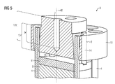
- the Figures 5 and 6 show a third embodiment of the invention in different perspectives.
- the first thread 7 is arranged in the fitting body 10.
- To the center of the first thread 7 are distributed in a radial distance a plurality of second thread 8 in the fitting body 10 are arranged in a circle.
- a pressure screw 14 is arranged, which is pressed in a tensioned state against the Ableitkla 2 and against the pressure plate 11.
- the first thread 7 extends over the first section 12 and the second thread 8 via the axial section 13.
- the first section 12 and the second section 13 overlap.
- the pressure screws 14 are preferably threaded pins , also called grub screws executed.
Landscapes
- Engineering & Computer Science (AREA)
- Microelectronics & Electronic Packaging (AREA)
- Physics & Mathematics (AREA)
- Electromagnetism (AREA)
- Thermistors And Varistors (AREA)
- Emergency Protection Circuit Devices (AREA)
Abstract
Description
- Die Erfindung betrifft Überspannungsableiter, wie sie zum Schutz vor Überspannungen in elektrischen Energieübertragungsnetzen eingesetzt werden. Ein solcher Überspannungsableiter ist einerseits elektrisch mit einer Hoch- oder Mittelspannungsübertragungsleitung verbunden, andererseits mit Erdpotential. Im Normalbetrieb wirkt der Überspannungsableiter wie ein Isolator. Bei Auftreten einer Überspannung durch zum Beispiel Blitzeinschlag oder Schaltvorgänge wird er Überspannungsableiter leitend und leitet die Überspannung zur Erde hin ab. Ist die Überspannung abgeklungen, so wird der Überspannungsableiter wieder isolierend. Dazu weist der Überspannungsableiter eine Ableitsäule mit einem spannungsabhängigen elektrischen Widerstand, einem sogenannten Varistor, auf. Unterhalb einer Schwellenspannung, die eine Materialeigenschaft des Varistors ist, ist die Ableitsäule hochohmig und wirkt als Isolator. Bei Überschreiten Schwellenspannung verringert sich der Widerstand des Varistors, die Ableitsäule wird leitend und leitet die Überspannung zur Erde hin ab.
- Für Anwendungen in elektrischen Übertragungsnetzen ist eine Ableitsäule eines Überspannungsableiters häufig als zylindrische Säule aus aufeinander gestapelten einzelnen Varistorblöcken aufgebaut. Die Varistorblöcke sind ihrerseits zylindrische, meist kreiszylindrische, Blöcke aus einem spannungsabhängigen Material wie beispielsweise Zinkoxid oder Siliziumkarbid. Diese sind mit ihren Stirnflächen aufeinander zur Ableitsäule gestapelt. Damit die Ableitsäule einerseits mechanisch stabil ist und andererseits die Varistorblöcke einen guten elektrischen Kontakt miteinander haben, muss die Ableitsäule unter Druck zusammengehalten werden. Grundsätzlich unterscheidet man zwei unterschiedliche Bauweisen.
- Beim sogenannten Rohr-Design ist die Ableitsäule in einem mechanisch stabilen Gehäuse angeordnet und zwischen Flanschen des Gehäuses eingespannt.
- Beim sogenannten Käfig-Design ist die Ableitsäule von einem Käfig aus Zugelementen, beispielsweise aus glasfaserverstärktem Kunststoff, umgeben, die in Endarmaturen verspannt sind und so die Ableitsäule zusammenhalten.
- Es gibt auch Mischformen, bei dem eine durch Zugelemente eingespannte Ableitsäule in einem mechanisch stabilen Gehäuse angeordnet ist. Dies erhöht die mechanische Stabilität und erleichtert die Montage.
- Für Freiluftanwendungen weist der Überspannungsableiter einen Außenmantel aus einem wetterfesten Material, wie beispielsweise Silikon, auf.
- Die Erfindung betrifft einen Überspannungsableiter im Käfig-Design unabhängig davon, ob dieser zusätzlich in einem mechanisch stabilen Gehäuse angeordnet ist.
- Die
WO 2006/125753 A1 zeigt einen solchen Überspannungsableiter. Die Endarmaturen, in denen die Zugelemente eingespannt sind, weisen eine durchgehende axiale Bohrung mit einem Gewinde auf. In dieses ist einerseits eine Druckschraube eingeschraubt, die einen axialen Druck auf die Ableitsäule ausübt. Andererseits ist in diese Bohrung ein von außen zugänglicher Anschlussbolzen eingeschraubt, der zum elektrischen Anschluss dient. Beide benötigen zur Übertragung der notwendigen Kräfte eine in dem Gewinde eingeschraubte Mindestlänge. Diese bestimmt im Wesentlichen die Dicke der Endarmatur. Bemühungen, die Endarmatur kompakter zu gestalten, um die Gesamtlänge des Überspannungsableiters zu verringern, werden durch die erforderliche Mindestlänge erschwert. - Aufgabe der Erfindung ist es, einen Überspannungsableiter mit kompakten Endarmaturen anzugeben.
- Dabei weist ein Überspannungsableiter eine sich entlang einer Längsachse erstreckende Ableitsäule auf, die aus mehreren aufeinandergestapelten Varistorblöcken gebildet ist. Die Ableitsäule ist mittels mehrerer diese radial umgebenden und in Endarmaturen festgelegten Zugelemente zwischen den Endarmaturen eingespannt. Zumindest eine der Endarmaturen weist ein erstes Gewinde zur Befestigung eines Anschlussbolzens auf. Der Anschlussbolzen dient zum Anschluss des Überspannungsableiters an eine Freileitung eines Energieübertragungsnetzes. Außerdem weist die Endarmatur einen Armaturkörper mit einem zweiten Gewinde zur Aufnahme einer Druckschraube zur Erzeugung einer axialen Kraft auf die Ableitsäule auf. Mittels der Druckschraube wird die Ableitsäule axial zusammengepresst um einen möglichst guten Kontakt zwischen den die Ableitsäule bildenden Varistorblöcken zu ermöglichen. Erfindungsgemäß ist vorgesehen, dass das erste Gewinde und das zweite Gewinde derart zueinander angeordnet sind, dass sie sich entlang eines axialen, also eines sich parallel zur Längsachse erstreckenden, Abschnitts überlappen. Das erste und zweite Gewinde sind also derart parallel zueinander und parallel zur Längsachse angeordnet, dass eine radiale, also senkrecht zur Längsachse ausgerichtete Ebene, die innerhalb von diesem axialen Abschnitt liegt, sowohl das erste Gewinde, als auch das zweite Gewinde schneidet. Dadurch kann der Armaturkörper und damit die Endarmatur in der Höhe um die Länge des axialen Abschnitts verkürzt gebaut werden.
- Vorzugsweise sind das erste und zweite Gewinde koaxial zueinander und zur Längsachse angeordnet. Dies erleichtert die Herstellung und Montage.
- In einer bevorzugten ersten Ausführungsform ist auch das erste Gewinde ein im Armaturkörper angeordnetes Innengewinde. Erstes und zweites Gewinde sind koaxial zueinander und zur Längsachse angeordnet. Die Druckschraube ist topfartig ausgeführt und in das zweite Gewinde eingeschraubt. Die Druckschraube weist einen zur Ableitsäule weisenden Boden und eine sich von diesem und der Ableitsäule weg erstreckende Seitenwand auf. Boden und Seitenwand umschließen einen hohlen Innenraum. Der Armaturkörper weist eine ringartige axiale Vertiefung auf, die sich in axialer Richtung vom inneren, also zur Ableitsäule weisenden Ende des ersten Gewindes nach außen, also von der Ableitsäule weg erstreckt. Das zweite Gewinde erstreckt sich in die axiale Vertiefung hinein. Es kann dabei auf der Außen- oder Innenwand der Vertiefung angeordnet sein.
- Vorzugsweise weist der Boden eine Werkzeugaufnahme zur Aufnahme eines Schraubwerkzeugs auf. Die Werkzeugaufnahme kann beispielsweise ein Sechskantloch zur Aufnahme eines Inbus-Schlüssels sein. Dadurch kann ein Werkzeug durch die Bohrung des ersten Gewindes eingeführt werden, um von außen die Druckschraube zu drehen und damit die Ableitsäule zu spannen.
- In einer bevorzugten Ausgestaltung der ersten Ausführungsform weist die Druckschraube ein oder mehrere Einspritzöffnungen auf, die dem Einspritzen von Vergussmasse in den hohlen Innenraum dienen. Bevorzugt erstreckt sich jede Einspritzöffnung vom Boden bis in die Seitenwand der Druckschraube. So kann beim Herstellen der Außenumhüllung, die üblicherweise durch Spritzgießen hergestellt wird, gleichzeitig der Innenraum mit Vergussmasse gefüllt und so abgedichtet werden. Aufwändige Dichtmaßnahmen können damit entfallen.
- Bevorzugt wird auch, dass das zweite Gewinde ein Innengewinde ist und die Druckschraube an ihrer Seitenwand ein entsprechendes Außengewinde aufweist. Die Druckschraube weist dabei eine zylindrische Außenmantelfläche mit einem zum zweiten Gewinde korrespondierenden Gewinde auf.
- In einer zweiten Ausführungsform der Erfindung ist der Armaturkörper ringartig mit einer zylindrischen Innenmantelfläche ausgeführt, wobei das zweite Gewinde auf der Innenmantelfläche angeordnet ist. Die Druckschraube weist dabei eine zylindrische Außenmantelfläche mit einem zum zweiten Gewinde korrespondierenden Gewinde auf. Zum Spannen der Ableitsäule wird der Armaturkörper festgehalten, während die Druckschraube mittels eines Werkzeugs gedreht wird. Alternativ kann die Druckschraube festgehalten werden und die beiden gegenüberliegenden Armaturkörper mitsamt der Ableitsäule und den Zugelementen gemeinsam gedreht werden. Vorzugsweise sind dabei bei einer der Endarmaturen das erste und zweite Gewinde als Linksgewinde und bei der gegenüberliegenden Endarmatur als Rechtsgewinde ausgeführt. So können in einem Arbeitsgang beide Endarmaturen gleichmäßig gespannt werden.
- Vorteilhaft ist bei der zweiten Ausführungsform, wenn die Druckschraube den Armaturkörper vollständig durchdringt, wobei das erste Gewinde in der Druckschraube angeordnet ist. So lässt sich die Druckschraube besonders einfach gestalten und herstellen.
- In einer dritten Ausführungsform der Erfindung ist das erste Gewinde im Armaturkörper angeordnet, wobei in einem radialen Abstand um das erste Gewinde mehrere zweite Gewinde um das erste Gewinde herum verteilt angeordnet sind, Dabei ist in jedem zweiten Gewinde eine Druckschraube angeordnet. Die Spannung der Ableitsäule erfolgt so außerhalb der Längsachse an mehreren Stellen, womit sich eine bessere Druckverteilung auf die Ableitsäule erreichen lässt.
- Im Folgenden wird die Erfindung anhand der Zeichnungen näher erläutert. Dabei zeigen:
- Figur 1
- eine Teilschnittdarstellung eines bekannten Überspannungsableiters,
- Figur 2
- eine herkömmliche Endarmatur,
- Figur 3
- eine erste Ausführungsform eines erfindungsgemäßen Überspannungsableiters,
- Figur 4
- eine zweite Ausführungsform eines erfindungsgemäßen Überspannungsableiters,
- Figur 5
- eine dritte Ausführungsform eines erfindungsgemäßen Überspannungsableiters,
- Figur 6
- eine weitere Ansicht der dritten Ausführungsform.
- Einander entsprechende Teile sind in allen Figuren mit den gleichen Bezugszeichen versehen.
- Die
Figur 1 zeigt einen herkömmlichen Überspannungsableiter 1 im sogenannten Käfig-Design mit einer aus mehreren Varistorelementen bestehenden Ableitsäule 2. Außer den Varistorelementen kann die Ableitsäule 2 noch weitere Elemente wie beispielsweise Metallblöcke (nicht dargestellt) zum Längenausgleich enthalten. Die Ableitsäule 2 wird an beiden Enden durch Endarmaturen 30 gehalten. Durch einen aus der Endarmatur 30 herausragenden Anschlussbolzen 15 kann der Überspannungsableiter 1 in das Stromversorgungssystem eingebunden werden. Um die erforderliche mechanische Festigkeit beispielsweise gegen Biegebeanspruchung zu erreichen, werden in den Endarmaturen 30 außen um die Ableitsäule herum und parallel zur Längsachse 40 des Überspannungsableiters liegende Zugelemente 4 eingespannt, die die Ableitsäule 2 unter Zug zusammenhalten. Diese Zugelemente 4 sind als Stäbe aus glasfaserverstärktem Kunststoff ausgeführt. Zum Schutz gegen Umwelteinflüsse ist der Überspannungsableiter oft mit einer äußeren Umhüllung 31 aus Silikon versehen. An der Außenseite der Umhüllung 31 sind Schirme 32 vorgesehen, um den Kriechweg des Stromes zu vergrößern. - Die
Figur 2 zeigt eine Endarmatur 30, wie sie in einem in derFigur 1 gezeigten Überspannungsableiter eingesetzt wird. Die am entgegengesetzten Ende des Überspannungsableiters angeordnete Endarmatur (kein Bezugszeichen da nicht sichtbar!) ist gleichartig zu dieser aufgebaut. In den Endarmaturen 30 sind Zugelemente 4 eingespannt. Diese können in der Endarmatur 30 verschraubt, verkeilt oder vercrimpt sein. Die Endarmaturen 30 weisen eine durchgehende Bohrung 6 auf. Diese weist im Unterschied zurWO 2006/125753 A1 hier Abschnitte 12 und 13 mit unterschiedlicher Weite auf. Der erste Abschnitt 12 weist ein erstes Gewinde 7 auf, der zweite Abschnitt 13 ein zweites Gewinde 8. Als Gewinde werden im Sinne der Erfindung Schraubengewinde verstanden, die als Innengewinde auf einer Innenmantelfläche einer kreiszylindrischen Bohrung oder als Außengewinde auf einer kreiszylindrischen Außenmantelfläche angeordnet sind. Der erste Abschnitt 12 mit dem ersten Gewinde 7 und der zweite Abschnitt 13 mit dem zweiten Gewinde 8 sind koaxial hintereinander angeordnet. Auf der Außenseite der Endarmatur 30 ist im ersten Abschnitt 12 ist ein Anschlussbolzen 15 in das erste Gewinde 7 eingeschraubt. Im zweiten Abschnitt 13 ist eine Druckschraube 14 in das zweite Gewinde 8 eingeschraubt. Die Druckschraube 14 wird von der Innenseite der Endarmatur 30 eingeschraubt und nach Montage der aus den Varistorblöcken 5 bestehenden Ableitsäule 2 und der Zugelemente 4 durch die zentrale Bohrung 6 mittels eines Werkzeugs in axialer Richtung zur Ableitsäule 2 hin eingeschraubt. Hierdurch wird eine Kraft auf die Ableitsäule 2 ausgeübt, die von den Zugelementen 4 aufgenommen wird. Zur besseren Druckverteilung kann zwischen der Druckschraube 14 und dem äußersten Varistorblock 5 der Ableitsäule 2 eine Druckscheibe 11 angeordnet sein. Nach dem Spannen der Ableitsäule 2 kann der Anschlussbolzen 15 in das erste Gewinde 7 der zentralen Bohrung 6 eingeschraubt werden. - Sowohl das erste Gewinde 7, als auch das zweite Gewinde 8 benötigen eine gewisse Mindestlänge L1 bzw. L2, da Anschlussbolzen 15 und Druckschraube 14 jeweils eine bestimmte Einschraubtiefe benötigen, um die auftretenden Kräfte auf den Flansch abtragen zu können. Insbesondere das zweite Gewinde 8 muss außerdem genügend Spielraum aufweisen, damit die Druckschraube 14 genügend weit aus dem zweiten Gewinde 8 heraus gedreht werden kann, um die notwendige Druckkraft auf die Ableitsäule 2 zu übertragen. Die notwendige Mindestlänge L1, L2 der Gewinde 7, 8 bestimmt die Mindestbauhöhe der Endarmatur 30 und beschränkt Bemühungen, diese kompakter zu gestalten.
- Die
Figur 3 zeigt eine erste Ausführungsform für eine erfindungsgemäße Endarmatur 3, die eine kompaktere Bauweise ermöglicht. Dabei ist gegenüber der Endarmatur 30 derFigur 2 die zentrale Bohrung 6 des Armaturkörpers 10 im Bereich des zweiten Abschnitts 13 im Durchmesser stark vergrößert. Statt einer massiven Druckschraube 14 ist diese hier topfartig ausgestaltet, mit einer hohlkreiszylindrischen Seitenwand 20 und einem kreisförmigen Boden 21, der die Seitenwand 20 stirnseitig abschließt. Der Boden 21 liegt an der Ableitsäule 2 an, die Seitenwand 20 erstreckt sich vom Boden 21 von der Ableitsäule 2 weg. Im Bereich der Seitenwand 20 weist der Armaturkörper 10 eine von der Ableitsäule 2 weg gerichtete ringartige axiale Vertiefung 23 auf, in die die Seitenwand 20 der Druckschraube 14 eintaucht. Das zweite Gewinde 8 erstreckt sich bis in diese Vertiefung 23 hinein. Der erste Abschnitt 12 mit dem ersten Gewinde 7 und der zweite Abschnitt 13 mit dem zweiten Gewinde 8 überlappen so in einem axialen Abschnitt 9. Das erste und zweite Gewinde 7,8 sind also derart parallel zueinander und parallel zur Längsachse 40 angeordnet, dass eine radiale, also senkrecht zur Längsachse ausgerichtete Ebene, die innerhalb von diesem axialen Abschnitt 9 liegt, sowohl das erste Gewinde 7, als auch das zweite Gewinde 8 schneidet. Dadurch kann der Armaturkörper 10 und damit die Endarmatur 3 in der Höhe um die Länge des Abschnitts 9 verkürzt gebaut werden. - Im Bereich des Bodens 21 weist die Druckschraube 14 eine Werkzeugaufnahme 16 hier in Form eines Innensechskant auf. In diese kann durch die zentrale Bohrung 6 von außen ein Werkzeug eingesetzt werden, um die Druckschraube 14 zu drehen und gegen die Ableitsäule 2 zu pressen, um die notwendige Druckkraft zu erzeugen. Statt eines Innensechskantes könnte der Boden 21 auch auf seiner der Ableitsäule 2 entgegengesetzten Seite eine Aufnahme für einen Steckschlüssel aufweisen.
- Der Boden 21 kann außerdem eine oder mehrere Einspritzöffnungen 17 aufweisen, die sich bis in die Seitenwand 20 hinein erstrecken. Durch diese Einspritzöffnungen 17 kann beim Guss der äußeren Umhüllung 31 Vergussmasse, beispielsweise Silikon, in den Innenraum 22 der Druckschraube 14 eintreten und so die zentrale Bohrung 6 abdichten. Ein bisher übliches Abdichten von der Außenseite der Endarmatur 3 kann damit entfallen.
- In einer zweiten Ausführungsform der Erfindung ist der Armaturkörper 10 ringartig ausgeführt. Er weist eine zylindrische Innenmantelfläche auf, auf der das zweite Gewinde 8 angeordnet ist. Die Druckschraube 14 weist eine zylindrische Außenmantelfläche mit einem dazu korrespondierenden Gewinde auf. In der hier dargestellten bevorzugten Ausführung durchdringt die Druckschraube 14 den Armaturkörper 10 vollständig. Das erste Gewinde 7 ist in der Druckschraube 14 angeordnet, vorzugsweise wie hier dargestellt, koaxial mit dem zweiten Gewinde 8. Das erste Gewinde erstreckt sich über einen ersten Abschnitt 12, das zweite über einen zweiten Abschnitt 13. Die beiden Abschnitte 12, 13 überlappen sich im axialen Abschnitt 9.
- Die
Figuren 5 und6 zeigen eine dritte Ausführungsform der Erfindung in unterschiedlichen Perspektiven. Hier ist das erste Gewinde 7 im Armaturkörper 10 angeordnet. Um den Mittelpunkt des ersten Gewindes 7 sind kreisförmig verteilt in einem radialen Abstand mehrere zweite Gewinde 8 im Armaturkörper 10 angeordnet. In jedem der zweiten Gewinde 8 ist eine Druckschraube 14 angeordnet, die in gespanntem Zustand gegen die Ableitsäule 2 beziehungsweise gegen die Druckscheibe 11 gepresst ist. Wie in den vorher beschriebenen Ausführungen erstreckt sich das erste Gewinde 7 über den ersten Abschnitt 12 und das zweite Gewinde 8 über den axialen Abschnitt 13. Im axialen Abschnitt 9 überlappen der erste Abschnitt 12 und der zweite Abschnitt 13. Die Druckschrauben 14 sind vorzugsweise als Gewindestifte, auch Madenschrauben genannt, ausgeführt.
Claims (9)
- Überspannungsableiter (1) mit einer sich entlang einer Längsachse (40) erstreckenden Ableitsäule, die mittels mehrerer die Ableitsäule (2) radial umgebenden und in Endarmaturen (3) festgelegten Zugelemente (4) zwischen den Endarmaturen (3) eingespannt ist, wobei zumindest eine der Endarmaturen (3) ein erstes Gewinde (7) zur Befestigung eines Anschlussbolzens (15) und einen Armaturkörper (10) mit einem zweiten Gewinde (8) zur Aufnahme einer Druckschraube (14) zur Erzeugung einer axialen Kraft auf die Ableitsäule (2) aufweist,
dadurch gekennzeichnet,
dass sich das erste und zweite Gewinde (7, 8) entlang eines axialen Abschnitts (9) überlappen. - Überspannungsableiter (1) nach Anspruch 1,
dadurch gekennzeichnet,
dass das erste und zweite Gewinde (7, 8) koaxial zueinander und zur Längsachse (40) angeordnet sind. - Überspannungsableiter (1) nach Anspruch 2,
dadurch gekennzeichnet,
dass das erste Gewinde (7) im Armaturkörper (10) angeordnet ist, wobei die Druckschraube (14) topfartig ausgeführt ist, mit einem zur Ableitsäule (2) weisenden Boden (21) und einer sich von diesem weg erstreckenden Seitenwand (20), die einen hohlen Innenraum (22) umschließen, wobei sich das zweite Gewinde (8) in eine axiale Vertiefung (23) des Armaturkörpers (10) hinein ausdehnt. - Überspannungsableiter (1) nach Anspruch 3,
dadurch gekennzeichnet,
dass der Boden (21) eine Werkzeugaufnahme (16) zur Aufnahme eines Schraubwerkzeugs aufweist. - Überspannungsableiter (1) nach Anspruch 3 oder 4,
dadurch gekennzeichnet,
dass die Druckschraube (14) Einspritzöffnungen (17) zum Einspritzen von Vergussmasse in den Innenraum (22) aufweist. - Überspannungsableiter (1) nach einem der Ansprüche 3 bis 5,
dadurch gekennzeichnet,
dass das zweite Gewinde (8) ein Innengewinde ist und die Druckschraube an ihrer Seitenwand (20) ein entsprechendes Außengewinde aufweist. - Überspannungsableiter (1) nach einem der Ansprüche 1 oder 2,
dadurch gekennzeichnet,
dass der Armaturkörper (10) ringartig mit einer zylindrischen Innenmantelfläche ausgeführt ist, wobei das zweite Gewinde (8) auf der Innenmantelfläche angeordnet ist und wobei die Druckschraube (14) eine zylindrische Außenmantelfläche mit einem zum zweiten Gewinde (8) korrespondierenden Gewinde aufweist. - Überspannungsableiter (1) nach Anspruch 7,
dadurch gekennzeichnet,
dass die Druckschraube (14) den Armaturkörper (10) vollständig durchdringt, wobei das erste Gewinde (7) in der Druckschraube angeordnet ist. - Überspannungsableiter (1) nach Anspruch 1,
dadurch gekennzeichnet,
dass das erste Gewinde (7) im Armaturkörper (10) angeordnet ist, wobei in einem radialen Abstand um das erste Gewinde (7) mehrere zweite Gewinde (8) um das erste Gewinde (7) herum verteilt angeordnet sind, wobei in jedem zweiten Gewinde (8) eine Druckschraube (14) angeordnet ist.
Priority Applications (3)
| Application Number | Priority Date | Filing Date | Title |
|---|---|---|---|
| EP15185825.5A EP3144942B1 (de) | 2015-09-18 | 2015-09-18 | Überspannungsableiter |
| CN201610811525.2A CN106952701B (zh) | 2015-09-18 | 2016-09-08 | 过电压防护放电器 |
| US15/268,780 US10504639B2 (en) | 2015-09-18 | 2016-09-19 | Overvoltage arrester |
Applications Claiming Priority (1)
| Application Number | Priority Date | Filing Date | Title |
|---|---|---|---|
| EP15185825.5A EP3144942B1 (de) | 2015-09-18 | 2015-09-18 | Überspannungsableiter |
Publications (2)
| Publication Number | Publication Date |
|---|---|
| EP3144942A1 true EP3144942A1 (de) | 2017-03-22 |
| EP3144942B1 EP3144942B1 (de) | 2018-02-21 |
Family
ID=54151142
Family Applications (1)
| Application Number | Title | Priority Date | Filing Date |
|---|---|---|---|
| EP15185825.5A Active EP3144942B1 (de) | 2015-09-18 | 2015-09-18 | Überspannungsableiter |
Country Status (3)
| Country | Link |
|---|---|
| US (1) | US10504639B2 (de) |
| EP (1) | EP3144942B1 (de) |
| CN (1) | CN106952701B (de) |
Cited By (1)
| Publication number | Priority date | Publication date | Assignee | Title |
|---|---|---|---|---|
| EP3232448A1 (de) * | 2016-04-13 | 2017-10-18 | Siemens Aktiengesellschaft | Überspannungsableiter |
Families Citing this family (3)
| Publication number | Priority date | Publication date | Assignee | Title |
|---|---|---|---|---|
| CN109215908B (zh) * | 2017-06-30 | 2021-08-20 | 河南平高通用电气有限公司 | 一种避雷器及其芯体和芯体上压盖 |
| CN110660545B (zh) * | 2019-08-08 | 2022-07-05 | 河南平高电气股份有限公司 | 一种罐式避雷器用压装芯体的压盖及罐式避雷器 |
| USD1019339S1 (en) * | 2021-12-29 | 2024-03-26 | The Trustees for the Time Being of the Live Line International Trust | Support arrangement |
Citations (6)
| Publication number | Priority date | Publication date | Assignee | Title |
|---|---|---|---|---|
| EP0726581A2 (de) * | 1995-02-11 | 1996-08-14 | ABB Management AG | Verfahren zur Herstellung eines Isolators |
| US6008975A (en) * | 1997-03-03 | 1999-12-28 | Mcgraw-Edison Company | Self-compressive surge arrester module and method of making same |
| WO2006125753A1 (de) | 2005-05-25 | 2006-11-30 | Tridelta Überspannungsableiter Gmbh | Überspannungsableiter mit käfig-design |
| DE102009008463A1 (de) * | 2009-02-09 | 2010-08-12 | Siemens Aktiengesellschaft | Überspannungsableiteranordnung |
| DE102009035646A1 (de) * | 2009-07-29 | 2011-02-10 | Siemens Aktiengesellschaft | Endarmatur für einen Überspannungsableiter und Verfahren zur Herstellung eines Überspannungsableiters |
| WO2012098250A1 (de) * | 2011-01-21 | 2012-07-26 | Tridelta Überspannungsableiter Gmbh | Überspannungsableiter mit käfig-design |
Family Cites Families (5)
| Publication number | Priority date | Publication date | Assignee | Title |
|---|---|---|---|---|
| SE504075C2 (sv) | 1994-08-29 | 1996-11-04 | Asea Brown Boveri | Ventilavledare |
| DE19622140A1 (de) * | 1996-06-01 | 1997-12-04 | Asea Brown Boveri | Überspannungsableiter |
| DE19650579A1 (de) | 1996-12-06 | 1998-06-10 | Asea Brown Boveri | Überspannungsableiter |
| DE19813135A1 (de) | 1998-03-25 | 1999-09-30 | Asea Brown Boveri | Überspannungsableiter |
| DE19940939C1 (de) * | 1999-08-23 | 2001-07-19 | Siemens Ag | Überspannungsableiter mit einem Verspannelement |
-
2015
- 2015-09-18 EP EP15185825.5A patent/EP3144942B1/de active Active
-
2016
- 2016-09-08 CN CN201610811525.2A patent/CN106952701B/zh active Active
- 2016-09-19 US US15/268,780 patent/US10504639B2/en not_active Expired - Fee Related
Patent Citations (6)
| Publication number | Priority date | Publication date | Assignee | Title |
|---|---|---|---|---|
| EP0726581A2 (de) * | 1995-02-11 | 1996-08-14 | ABB Management AG | Verfahren zur Herstellung eines Isolators |
| US6008975A (en) * | 1997-03-03 | 1999-12-28 | Mcgraw-Edison Company | Self-compressive surge arrester module and method of making same |
| WO2006125753A1 (de) | 2005-05-25 | 2006-11-30 | Tridelta Überspannungsableiter Gmbh | Überspannungsableiter mit käfig-design |
| DE102009008463A1 (de) * | 2009-02-09 | 2010-08-12 | Siemens Aktiengesellschaft | Überspannungsableiteranordnung |
| DE102009035646A1 (de) * | 2009-07-29 | 2011-02-10 | Siemens Aktiengesellschaft | Endarmatur für einen Überspannungsableiter und Verfahren zur Herstellung eines Überspannungsableiters |
| WO2012098250A1 (de) * | 2011-01-21 | 2012-07-26 | Tridelta Überspannungsableiter Gmbh | Überspannungsableiter mit käfig-design |
Cited By (2)
| Publication number | Priority date | Publication date | Assignee | Title |
|---|---|---|---|---|
| EP3232448A1 (de) * | 2016-04-13 | 2017-10-18 | Siemens Aktiengesellschaft | Überspannungsableiter |
| US10043603B2 (en) | 2016-04-13 | 2018-08-07 | Siemens Aktiengesellschaft | Surge arrester |
Also Published As
| Publication number | Publication date |
|---|---|
| US20170084367A1 (en) | 2017-03-23 |
| EP3144942B1 (de) | 2018-02-21 |
| CN106952701B (zh) | 2020-01-24 |
| CN106952701A (zh) | 2017-07-14 |
| US10504639B2 (en) | 2019-12-10 |
Similar Documents
| Publication | Publication Date | Title |
|---|---|---|
| EP1883934B1 (de) | Überspannungsableiter mit käfig-design | |
| EP1977434B1 (de) | Überspannungsableiter mit käfig-design und herstellungsverfahren für diesen | |
| EP3144942B1 (de) | Überspannungsableiter | |
| DE19813135A1 (de) | Überspannungsableiter | |
| DE3610742A1 (de) | Stuetzisolator | |
| EP3469672B1 (de) | Isolator | |
| WO2019007566A1 (de) | Ableiter zum schutz vor überspannungen | |
| WO2015032671A1 (de) | Gasisolierter überspannungsableiter | |
| EP0810705B1 (de) | Isolator | |
| DE19741830B4 (de) | Sicherungssystem zum Absichern von elektrischen Stromkreisen, insbesondere in Fahrzeugen | |
| EP2940819A1 (de) | Kabelendgarnitur | |
| EP3048617B1 (de) | Überspannungsableiter | |
| EP3082136B1 (de) | Gasisolierter überspannungsableiter | |
| EP2764521A1 (de) | Überspannungsableiter | |
| EP1382047A1 (de) | Magnetspulenanordnung | |
| WO2012123323A1 (de) | Elektrische kontaktanordnung | |
| WO1993020599A1 (de) | Vorrichtung zur herstellung einer lösbaren verbindung zwischen einer signalleitung und einer anschlussbuchse an einem bauteil eines mittelspannungs- oder hochspannungsenergieversorgungssystems | |
| EP3721517A1 (de) | Blitzstromableitvorrichtung | |
| EP3001437B1 (de) | Durchführungssystem | |
| EP3358690A1 (de) | Verbindungsmuffe | |
| EP1383142A1 (de) | Steckbarer elektrischer Apparat, insbesondere Überspannungsableiter | |
| DE102009008463A1 (de) | Überspannungsableiteranordnung | |
| DE102014225748B4 (de) | Anschlussadapter für ein Hochspannungsbauteil sowie eine Hochspannungsbaugruppe | |
| WO2014016042A1 (de) | Überspannungsableiter mit durch schlingen gehaltenen zugelementen | |
| DE202021100335U1 (de) | Spannungswandler und elektrischer Schrank |
Legal Events
| Date | Code | Title | Description |
|---|---|---|---|
| PUAI | Public reference made under article 153(3) epc to a published international application that has entered the european phase |
Free format text: ORIGINAL CODE: 0009012 |
|
| AK | Designated contracting states |
Kind code of ref document: A1 Designated state(s): AL AT BE BG CH CY CZ DE DK EE ES FI FR GB GR HR HU IE IS IT LI LT LU LV MC MK MT NL NO PL PT RO RS SE SI SK SM TR |
|
| AX | Request for extension of the european patent |
Extension state: BA ME |
|
| RAP1 | Party data changed (applicant data changed or rights of an application transferred) |
Owner name: SIEMENS AKTIENGESELLSCHAFT |
|
| GRAP | Despatch of communication of intention to grant a patent |
Free format text: ORIGINAL CODE: EPIDOSNIGR1 |
|
| 17P | Request for examination filed |
Effective date: 20170821 |
|
| RBV | Designated contracting states (corrected) |
Designated state(s): AL AT BE BG CH CY CZ DE DK EE ES FI FR GB GR HR HU IE IS IT LI LT LU LV MC MK MT NL NO PL PT RO RS SE SI SK SM TR |
|
| INTG | Intention to grant announced |
Effective date: 20170919 |
|
| GRAS | Grant fee paid |
Free format text: ORIGINAL CODE: EPIDOSNIGR3 |
|
| GRAA | (expected) grant |
Free format text: ORIGINAL CODE: 0009210 |
|
| AK | Designated contracting states |
Kind code of ref document: B1 Designated state(s): AL AT BE BG CH CY CZ DE DK EE ES FI FR GB GR HR HU IE IS IT LI LT LU LV MC MK MT NL NO PL PT RO RS SE SI SK SM TR |
|
| REG | Reference to a national code |
Ref country code: GB Ref legal event code: FG4D Free format text: NOT ENGLISH |
|
| REG | Reference to a national code |
Ref country code: CH Ref legal event code: EP |
|
| REG | Reference to a national code |
Ref country code: CH Ref legal event code: NV Representative=s name: SIEMENS SCHWEIZ AG, CH Ref country code: AT Ref legal event code: REF Ref document number: 972548 Country of ref document: AT Kind code of ref document: T Effective date: 20180315 |
|
| REG | Reference to a national code |
Ref country code: IE Ref legal event code: FG4D Free format text: LANGUAGE OF EP DOCUMENT: GERMAN |
|
| REG | Reference to a national code |
Ref country code: DE Ref legal event code: R096 Ref document number: 502015003137 Country of ref document: DE |
|
| REG | Reference to a national code |
Ref country code: NL Ref legal event code: MP Effective date: 20180221 |
|
| REG | Reference to a national code |
Ref country code: LT Ref legal event code: MG4D |
|
| PG25 | Lapsed in a contracting state [announced via postgrant information from national office to epo] |
Ref country code: NL Free format text: LAPSE BECAUSE OF FAILURE TO SUBMIT A TRANSLATION OF THE DESCRIPTION OR TO PAY THE FEE WITHIN THE PRESCRIBED TIME-LIMIT Effective date: 20180221 Ref country code: ES Free format text: LAPSE BECAUSE OF FAILURE TO SUBMIT A TRANSLATION OF THE DESCRIPTION OR TO PAY THE FEE WITHIN THE PRESCRIBED TIME-LIMIT Effective date: 20180221 Ref country code: CY Free format text: LAPSE BECAUSE OF FAILURE TO SUBMIT A TRANSLATION OF THE DESCRIPTION OR TO PAY THE FEE WITHIN THE PRESCRIBED TIME-LIMIT Effective date: 20180221 Ref country code: LT Free format text: LAPSE BECAUSE OF FAILURE TO SUBMIT A TRANSLATION OF THE DESCRIPTION OR TO PAY THE FEE WITHIN THE PRESCRIBED TIME-LIMIT Effective date: 20180221 Ref country code: FI Free format text: LAPSE BECAUSE OF FAILURE TO SUBMIT A TRANSLATION OF THE DESCRIPTION OR TO PAY THE FEE WITHIN THE PRESCRIBED TIME-LIMIT Effective date: 20180221 Ref country code: HR Free format text: LAPSE BECAUSE OF FAILURE TO SUBMIT A TRANSLATION OF THE DESCRIPTION OR TO PAY THE FEE WITHIN THE PRESCRIBED TIME-LIMIT Effective date: 20180221 Ref country code: NO Free format text: LAPSE BECAUSE OF FAILURE TO SUBMIT A TRANSLATION OF THE DESCRIPTION OR TO PAY THE FEE WITHIN THE PRESCRIBED TIME-LIMIT Effective date: 20180521 |
|
| PG25 | Lapsed in a contracting state [announced via postgrant information from national office to epo] |
Ref country code: GR Free format text: LAPSE BECAUSE OF FAILURE TO SUBMIT A TRANSLATION OF THE DESCRIPTION OR TO PAY THE FEE WITHIN THE PRESCRIBED TIME-LIMIT Effective date: 20180522 Ref country code: BG Free format text: LAPSE BECAUSE OF FAILURE TO SUBMIT A TRANSLATION OF THE DESCRIPTION OR TO PAY THE FEE WITHIN THE PRESCRIBED TIME-LIMIT Effective date: 20180521 Ref country code: RS Free format text: LAPSE BECAUSE OF FAILURE TO SUBMIT A TRANSLATION OF THE DESCRIPTION OR TO PAY THE FEE WITHIN THE PRESCRIBED TIME-LIMIT Effective date: 20180221 Ref country code: LV Free format text: LAPSE BECAUSE OF FAILURE TO SUBMIT A TRANSLATION OF THE DESCRIPTION OR TO PAY THE FEE WITHIN THE PRESCRIBED TIME-LIMIT Effective date: 20180221 Ref country code: SE Free format text: LAPSE BECAUSE OF FAILURE TO SUBMIT A TRANSLATION OF THE DESCRIPTION OR TO PAY THE FEE WITHIN THE PRESCRIBED TIME-LIMIT Effective date: 20180221 |
|
| REG | Reference to a national code |
Ref country code: FR Ref legal event code: PLFP Year of fee payment: 4 |
|
| PG25 | Lapsed in a contracting state [announced via postgrant information from national office to epo] |
Ref country code: MT Free format text: LAPSE BECAUSE OF FAILURE TO SUBMIT A TRANSLATION OF THE DESCRIPTION OR TO PAY THE FEE WITHIN THE PRESCRIBED TIME-LIMIT Effective date: 20180221 |
|
| PG25 | Lapsed in a contracting state [announced via postgrant information from national office to epo] |
Ref country code: RO Free format text: LAPSE BECAUSE OF FAILURE TO SUBMIT A TRANSLATION OF THE DESCRIPTION OR TO PAY THE FEE WITHIN THE PRESCRIBED TIME-LIMIT Effective date: 20180221 Ref country code: AL Free format text: LAPSE BECAUSE OF FAILURE TO SUBMIT A TRANSLATION OF THE DESCRIPTION OR TO PAY THE FEE WITHIN THE PRESCRIBED TIME-LIMIT Effective date: 20180221 Ref country code: PL Free format text: LAPSE BECAUSE OF FAILURE TO SUBMIT A TRANSLATION OF THE DESCRIPTION OR TO PAY THE FEE WITHIN THE PRESCRIBED TIME-LIMIT Effective date: 20180221 Ref country code: EE Free format text: LAPSE BECAUSE OF FAILURE TO SUBMIT A TRANSLATION OF THE DESCRIPTION OR TO PAY THE FEE WITHIN THE PRESCRIBED TIME-LIMIT Effective date: 20180221 Ref country code: IT Free format text: LAPSE BECAUSE OF FAILURE TO SUBMIT A TRANSLATION OF THE DESCRIPTION OR TO PAY THE FEE WITHIN THE PRESCRIBED TIME-LIMIT Effective date: 20180221 |
|
| REG | Reference to a national code |
Ref country code: DE Ref legal event code: R097 Ref document number: 502015003137 Country of ref document: DE |
|
| PG25 | Lapsed in a contracting state [announced via postgrant information from national office to epo] |
Ref country code: SM Free format text: LAPSE BECAUSE OF FAILURE TO SUBMIT A TRANSLATION OF THE DESCRIPTION OR TO PAY THE FEE WITHIN THE PRESCRIBED TIME-LIMIT Effective date: 20180221 Ref country code: DK Free format text: LAPSE BECAUSE OF FAILURE TO SUBMIT A TRANSLATION OF THE DESCRIPTION OR TO PAY THE FEE WITHIN THE PRESCRIBED TIME-LIMIT Effective date: 20180221 Ref country code: CZ Free format text: LAPSE BECAUSE OF FAILURE TO SUBMIT A TRANSLATION OF THE DESCRIPTION OR TO PAY THE FEE WITHIN THE PRESCRIBED TIME-LIMIT Effective date: 20180221 Ref country code: SK Free format text: LAPSE BECAUSE OF FAILURE TO SUBMIT A TRANSLATION OF THE DESCRIPTION OR TO PAY THE FEE WITHIN THE PRESCRIBED TIME-LIMIT Effective date: 20180221 |
|
| PLBE | No opposition filed within time limit |
Free format text: ORIGINAL CODE: 0009261 |
|
| STAA | Information on the status of an ep patent application or granted ep patent |
Free format text: STATUS: NO OPPOSITION FILED WITHIN TIME LIMIT |
|
| 26N | No opposition filed |
Effective date: 20181122 |
|
| PG25 | Lapsed in a contracting state [announced via postgrant information from national office to epo] |
Ref country code: SI Free format text: LAPSE BECAUSE OF FAILURE TO SUBMIT A TRANSLATION OF THE DESCRIPTION OR TO PAY THE FEE WITHIN THE PRESCRIBED TIME-LIMIT Effective date: 20180221 |
|
| PG25 | Lapsed in a contracting state [announced via postgrant information from national office to epo] |
Ref country code: MC Free format text: LAPSE BECAUSE OF FAILURE TO SUBMIT A TRANSLATION OF THE DESCRIPTION OR TO PAY THE FEE WITHIN THE PRESCRIBED TIME-LIMIT Effective date: 20180221 |
|
| REG | Reference to a national code |
Ref country code: BE Ref legal event code: MM Effective date: 20180930 |
|
| REG | Reference to a national code |
Ref country code: IE Ref legal event code: MM4A |
|
| PG25 | Lapsed in a contracting state [announced via postgrant information from national office to epo] |
Ref country code: LU Free format text: LAPSE BECAUSE OF NON-PAYMENT OF DUE FEES Effective date: 20180918 |
|
| PG25 | Lapsed in a contracting state [announced via postgrant information from national office to epo] |
Ref country code: IE Free format text: LAPSE BECAUSE OF NON-PAYMENT OF DUE FEES Effective date: 20180918 |
|
| PG25 | Lapsed in a contracting state [announced via postgrant information from national office to epo] |
Ref country code: BE Free format text: LAPSE BECAUSE OF NON-PAYMENT OF DUE FEES Effective date: 20180930 |
|
| PG25 | Lapsed in a contracting state [announced via postgrant information from national office to epo] |
Ref country code: TR Free format text: LAPSE BECAUSE OF FAILURE TO SUBMIT A TRANSLATION OF THE DESCRIPTION OR TO PAY THE FEE WITHIN THE PRESCRIBED TIME-LIMIT Effective date: 20180221 |
|
| PG25 | Lapsed in a contracting state [announced via postgrant information from national office to epo] |
Ref country code: PT Free format text: LAPSE BECAUSE OF FAILURE TO SUBMIT A TRANSLATION OF THE DESCRIPTION OR TO PAY THE FEE WITHIN THE PRESCRIBED TIME-LIMIT Effective date: 20180221 |
|
| PG25 | Lapsed in a contracting state [announced via postgrant information from national office to epo] |
Ref country code: HU Free format text: LAPSE BECAUSE OF FAILURE TO SUBMIT A TRANSLATION OF THE DESCRIPTION OR TO PAY THE FEE WITHIN THE PRESCRIBED TIME-LIMIT; INVALID AB INITIO Effective date: 20150918 Ref country code: MK Free format text: LAPSE BECAUSE OF NON-PAYMENT OF DUE FEES Effective date: 20180221 |
|
| PG25 | Lapsed in a contracting state [announced via postgrant information from national office to epo] |
Ref country code: IS Free format text: LAPSE BECAUSE OF FAILURE TO SUBMIT A TRANSLATION OF THE DESCRIPTION OR TO PAY THE FEE WITHIN THE PRESCRIBED TIME-LIMIT Effective date: 20180621 |
|
| GBPC | Gb: european patent ceased through non-payment of renewal fee |
Effective date: 20190918 |
|
| PG25 | Lapsed in a contracting state [announced via postgrant information from national office to epo] |
Ref country code: GB Free format text: LAPSE BECAUSE OF NON-PAYMENT OF DUE FEES Effective date: 20190918 |
|
| REG | Reference to a national code |
Ref country code: DE Ref legal event code: R081 Ref document number: 502015003137 Country of ref document: DE Owner name: SIEMENS ENERGY GLOBAL GMBH & CO. KG, DE Free format text: FORMER OWNER: SIEMENS AKTIENGESELLSCHAFT, 80333 MUENCHEN, DE |
|
| REG | Reference to a national code |
Ref country code: AT Ref legal event code: MM01 Ref document number: 972548 Country of ref document: AT Kind code of ref document: T Effective date: 20200918 |
|
| PG25 | Lapsed in a contracting state [announced via postgrant information from national office to epo] |
Ref country code: AT Free format text: LAPSE BECAUSE OF NON-PAYMENT OF DUE FEES Effective date: 20200918 |
|
| PGFP | Annual fee paid to national office [announced via postgrant information from national office to epo] |
Ref country code: FR Payment date: 20230926 Year of fee payment: 9 Ref country code: DE Payment date: 20230928 Year of fee payment: 9 |
|
| PGFP | Annual fee paid to national office [announced via postgrant information from national office to epo] |
Ref country code: CH Payment date: 20231001 Year of fee payment: 9 |