EP3144716A1 - Dispositif d'affichage et son procédé d'affichage - Google Patents
Dispositif d'affichage et son procédé d'affichage Download PDFInfo
- Publication number
- EP3144716A1 EP3144716A1 EP15792724.5A EP15792724A EP3144716A1 EP 3144716 A1 EP3144716 A1 EP 3144716A1 EP 15792724 A EP15792724 A EP 15792724A EP 3144716 A1 EP3144716 A1 EP 3144716A1
- Authority
- EP
- European Patent Office
- Prior art keywords
- image
- display
- beam splitter
- mirror
- display device
- Prior art date
- Legal status (The legal status is an assumption and is not a legal conclusion. Google has not performed a legal analysis and makes no representation as to the accuracy of the status listed.)
- Granted
Links
- 238000000034 method Methods 0.000 title claims description 15
- 230000003287 optical effect Effects 0.000 claims description 32
- 230000010287 polarization Effects 0.000 claims description 6
- 238000009826 distribution Methods 0.000 claims description 2
- 239000011521 glass Substances 0.000 description 24
- 238000010586 diagram Methods 0.000 description 12
- 239000000463 material Substances 0.000 description 5
- 238000004891 communication Methods 0.000 description 4
- 238000004590 computer program Methods 0.000 description 4
- 238000001228 spectrum Methods 0.000 description 4
- 239000000470 constituent Substances 0.000 description 3
- 239000004973 liquid crystal related substance Substances 0.000 description 3
- 230000005540 biological transmission Effects 0.000 description 2
- 238000006073 displacement reaction Methods 0.000 description 2
- 238000012986 modification Methods 0.000 description 2
- 230000004048 modification Effects 0.000 description 2
- 239000004065 semiconductor Substances 0.000 description 2
- 238000002834 transmittance Methods 0.000 description 2
- 230000000903 blocking effect Effects 0.000 description 1
- 238000013461 design Methods 0.000 description 1
- 238000002955 isolation Methods 0.000 description 1
- 238000012545 processing Methods 0.000 description 1
- 238000013519 translation Methods 0.000 description 1
Images


Classifications
-
- G—PHYSICS
- G02—OPTICS
- G02B—OPTICAL ELEMENTS, SYSTEMS OR APPARATUS
- G02B27/00—Optical systems or apparatus not provided for by any of the groups G02B1/00 - G02B26/00, G02B30/00
- G02B27/01—Head-up displays
- G02B27/0101—Head-up displays characterised by optical features
-
- B—PERFORMING OPERATIONS; TRANSPORTING
- B60—VEHICLES IN GENERAL
- B60K—ARRANGEMENT OR MOUNTING OF PROPULSION UNITS OR OF TRANSMISSIONS IN VEHICLES; ARRANGEMENT OR MOUNTING OF PLURAL DIVERSE PRIME-MOVERS IN VEHICLES; AUXILIARY DRIVES FOR VEHICLES; INSTRUMENTATION OR DASHBOARDS FOR VEHICLES; ARRANGEMENTS IN CONNECTION WITH COOLING, AIR INTAKE, GAS EXHAUST OR FUEL SUPPLY OF PROPULSION UNITS IN VEHICLES
- B60K35/00—Instruments specially adapted for vehicles; Arrangement of instruments in or on vehicles
- B60K35/20—Output arrangements, i.e. from vehicle to user, associated with vehicle functions or specially adapted therefor
- B60K35/21—Output arrangements, i.e. from vehicle to user, associated with vehicle functions or specially adapted therefor using visual output, e.g. blinking lights or matrix displays
- B60K35/23—Head-up displays [HUD]
-
- B—PERFORMING OPERATIONS; TRANSPORTING
- B60—VEHICLES IN GENERAL
- B60K—ARRANGEMENT OR MOUNTING OF PROPULSION UNITS OR OF TRANSMISSIONS IN VEHICLES; ARRANGEMENT OR MOUNTING OF PLURAL DIVERSE PRIME-MOVERS IN VEHICLES; AUXILIARY DRIVES FOR VEHICLES; INSTRUMENTATION OR DASHBOARDS FOR VEHICLES; ARRANGEMENTS IN CONNECTION WITH COOLING, AIR INTAKE, GAS EXHAUST OR FUEL SUPPLY OF PROPULSION UNITS IN VEHICLES
- B60K35/00—Instruments specially adapted for vehicles; Arrangement of instruments in or on vehicles
- B60K35/20—Output arrangements, i.e. from vehicle to user, associated with vehicle functions or specially adapted therefor
- B60K35/29—Instruments characterised by the way in which information is handled, e.g. showing information on plural displays or prioritising information according to driving conditions
-
- B—PERFORMING OPERATIONS; TRANSPORTING
- B60—VEHICLES IN GENERAL
- B60K—ARRANGEMENT OR MOUNTING OF PROPULSION UNITS OR OF TRANSMISSIONS IN VEHICLES; ARRANGEMENT OR MOUNTING OF PLURAL DIVERSE PRIME-MOVERS IN VEHICLES; AUXILIARY DRIVES FOR VEHICLES; INSTRUMENTATION OR DASHBOARDS FOR VEHICLES; ARRANGEMENTS IN CONNECTION WITH COOLING, AIR INTAKE, GAS EXHAUST OR FUEL SUPPLY OF PROPULSION UNITS IN VEHICLES
- B60K35/00—Instruments specially adapted for vehicles; Arrangement of instruments in or on vehicles
- B60K35/60—Instruments characterised by their location or relative disposition in or on vehicles
-
- G—PHYSICS
- G02—OPTICS
- G02B—OPTICAL ELEMENTS, SYSTEMS OR APPARATUS
- G02B27/00—Optical systems or apparatus not provided for by any of the groups G02B1/00 - G02B26/00, G02B30/00
- G02B27/10—Beam splitting or combining systems
- G02B27/14—Beam splitting or combining systems operating by reflection only
- G02B27/141—Beam splitting or combining systems operating by reflection only using dichroic mirrors
-
- G—PHYSICS
- G02—OPTICS
- G02B—OPTICAL ELEMENTS, SYSTEMS OR APPARATUS
- G02B27/00—Optical systems or apparatus not provided for by any of the groups G02B1/00 - G02B26/00, G02B30/00
- G02B27/28—Optical systems or apparatus not provided for by any of the groups G02B1/00 - G02B26/00, G02B30/00 for polarising
- G02B27/286—Optical systems or apparatus not provided for by any of the groups G02B1/00 - G02B26/00, G02B30/00 for polarising for controlling or changing the state of polarisation, e.g. transforming one polarisation state into another
-
- G—PHYSICS
- G02—OPTICS
- G02B—OPTICAL ELEMENTS, SYSTEMS OR APPARATUS
- G02B5/00—Optical elements other than lenses
- G02B5/30—Polarising elements
-
- G—PHYSICS
- G02—OPTICS
- G02B—OPTICAL ELEMENTS, SYSTEMS OR APPARATUS
- G02B5/00—Optical elements other than lenses
- G02B5/30—Polarising elements
- G02B5/3016—Polarising elements involving passive liquid crystal elements
-
- G—PHYSICS
- G02—OPTICS
- G02B—OPTICAL ELEMENTS, SYSTEMS OR APPARATUS
- G02B5/00—Optical elements other than lenses
- G02B5/32—Holograms used as optical elements
-
- G—PHYSICS
- G03—PHOTOGRAPHY; CINEMATOGRAPHY; ANALOGOUS TECHNIQUES USING WAVES OTHER THAN OPTICAL WAVES; ELECTROGRAPHY; HOLOGRAPHY
- G03B—APPARATUS OR ARRANGEMENTS FOR TAKING PHOTOGRAPHS OR FOR PROJECTING OR VIEWING THEM; APPARATUS OR ARRANGEMENTS EMPLOYING ANALOGOUS TECHNIQUES USING WAVES OTHER THAN OPTICAL WAVES; ACCESSORIES THEREFOR
- G03B21/00—Projectors or projection-type viewers; Accessories therefor
- G03B21/14—Details
- G03B21/28—Reflectors in projection beam
-
- G—PHYSICS
- G09—EDUCATION; CRYPTOGRAPHY; DISPLAY; ADVERTISING; SEALS
- G09B—EDUCATIONAL OR DEMONSTRATION APPLIANCES; APPLIANCES FOR TEACHING, OR COMMUNICATING WITH, THE BLIND, DEAF OR MUTE; MODELS; PLANETARIA; GLOBES; MAPS; DIAGRAMS
- G09B9/00—Simulators for teaching or training purposes
- G09B9/02—Simulators for teaching or training purposes for teaching control of vehicles or other craft
- G09B9/08—Simulators for teaching or training purposes for teaching control of vehicles or other craft for teaching control of aircraft, e.g. Link trainer
- G09B9/30—Simulation of view from aircraft
- G09B9/32—Simulation of view from aircraft by projected image
- G09B9/326—Simulation of view from aircraft by projected image the image being transformed by optical means
-
- G—PHYSICS
- G09—EDUCATION; CRYPTOGRAPHY; DISPLAY; ADVERTISING; SEALS
- G09G—ARRANGEMENTS OR CIRCUITS FOR CONTROL OF INDICATING DEVICES USING STATIC MEANS TO PRESENT VARIABLE INFORMATION
- G09G3/00—Control arrangements or circuits, of interest only in connection with visual indicators other than cathode-ray tubes
- G09G3/001—Control arrangements or circuits, of interest only in connection with visual indicators other than cathode-ray tubes using specific devices not provided for in groups G09G3/02 - G09G3/36, e.g. using an intermediate record carrier such as a film slide; Projection systems; Display of non-alphanumerical information, solely or in combination with alphanumerical information, e.g. digital display on projected diapositive as background
- G09G3/002—Control arrangements or circuits, of interest only in connection with visual indicators other than cathode-ray tubes using specific devices not provided for in groups G09G3/02 - G09G3/36, e.g. using an intermediate record carrier such as a film slide; Projection systems; Display of non-alphanumerical information, solely or in combination with alphanumerical information, e.g. digital display on projected diapositive as background to project the image of a two-dimensional display, such as an array of light emitting or modulating elements or a CRT
-
- G—PHYSICS
- G09—EDUCATION; CRYPTOGRAPHY; DISPLAY; ADVERTISING; SEALS
- G09G—ARRANGEMENTS OR CIRCUITS FOR CONTROL OF INDICATING DEVICES USING STATIC MEANS TO PRESENT VARIABLE INFORMATION
- G09G3/00—Control arrangements or circuits, of interest only in connection with visual indicators other than cathode-ray tubes
- G09G3/20—Control arrangements or circuits, of interest only in connection with visual indicators other than cathode-ray tubes for presentation of an assembly of a number of characters, e.g. a page, by composing the assembly by combination of individual elements arranged in a matrix no fixed position being assigned to or needed to be assigned to the individual characters or partial characters
-
- G—PHYSICS
- G09—EDUCATION; CRYPTOGRAPHY; DISPLAY; ADVERTISING; SEALS
- G09G—ARRANGEMENTS OR CIRCUITS FOR CONTROL OF INDICATING DEVICES USING STATIC MEANS TO PRESENT VARIABLE INFORMATION
- G09G5/00—Control arrangements or circuits for visual indicators common to cathode-ray tube indicators and other visual indicators
-
- B—PERFORMING OPERATIONS; TRANSPORTING
- B60—VEHICLES IN GENERAL
- B60K—ARRANGEMENT OR MOUNTING OF PROPULSION UNITS OR OF TRANSMISSIONS IN VEHICLES; ARRANGEMENT OR MOUNTING OF PLURAL DIVERSE PRIME-MOVERS IN VEHICLES; AUXILIARY DRIVES FOR VEHICLES; INSTRUMENTATION OR DASHBOARDS FOR VEHICLES; ARRANGEMENTS IN CONNECTION WITH COOLING, AIR INTAKE, GAS EXHAUST OR FUEL SUPPLY OF PROPULSION UNITS IN VEHICLES
- B60K2360/00—Indexing scheme associated with groups B60K35/00 or B60K37/00 relating to details of instruments or dashboards
- B60K2360/18—Information management
- B60K2360/182—Distributing information between displays
-
- B—PERFORMING OPERATIONS; TRANSPORTING
- B60—VEHICLES IN GENERAL
- B60K—ARRANGEMENT OR MOUNTING OF PROPULSION UNITS OR OF TRANSMISSIONS IN VEHICLES; ARRANGEMENT OR MOUNTING OF PLURAL DIVERSE PRIME-MOVERS IN VEHICLES; AUXILIARY DRIVES FOR VEHICLES; INSTRUMENTATION OR DASHBOARDS FOR VEHICLES; ARRANGEMENTS IN CONNECTION WITH COOLING, AIR INTAKE, GAS EXHAUST OR FUEL SUPPLY OF PROPULSION UNITS IN VEHICLES
- B60K2360/00—Indexing scheme associated with groups B60K35/00 or B60K37/00 relating to details of instruments or dashboards
- B60K2360/20—Optical features of instruments
- B60K2360/23—Optical features of instruments using reflectors
-
- B—PERFORMING OPERATIONS; TRANSPORTING
- B60—VEHICLES IN GENERAL
- B60K—ARRANGEMENT OR MOUNTING OF PROPULSION UNITS OR OF TRANSMISSIONS IN VEHICLES; ARRANGEMENT OR MOUNTING OF PLURAL DIVERSE PRIME-MOVERS IN VEHICLES; AUXILIARY DRIVES FOR VEHICLES; INSTRUMENTATION OR DASHBOARDS FOR VEHICLES; ARRANGEMENTS IN CONNECTION WITH COOLING, AIR INTAKE, GAS EXHAUST OR FUEL SUPPLY OF PROPULSION UNITS IN VEHICLES
- B60K2360/00—Indexing scheme associated with groups B60K35/00 or B60K37/00 relating to details of instruments or dashboards
- B60K2360/20—Optical features of instruments
- B60K2360/25—Optical features of instruments using filters
-
- B—PERFORMING OPERATIONS; TRANSPORTING
- B60—VEHICLES IN GENERAL
- B60K—ARRANGEMENT OR MOUNTING OF PROPULSION UNITS OR OF TRANSMISSIONS IN VEHICLES; ARRANGEMENT OR MOUNTING OF PLURAL DIVERSE PRIME-MOVERS IN VEHICLES; AUXILIARY DRIVES FOR VEHICLES; INSTRUMENTATION OR DASHBOARDS FOR VEHICLES; ARRANGEMENTS IN CONNECTION WITH COOLING, AIR INTAKE, GAS EXHAUST OR FUEL SUPPLY OF PROPULSION UNITS IN VEHICLES
- B60K2360/00—Indexing scheme associated with groups B60K35/00 or B60K37/00 relating to details of instruments or dashboards
- B60K2360/20—Optical features of instruments
- B60K2360/29—Holographic features
-
- B—PERFORMING OPERATIONS; TRANSPORTING
- B60—VEHICLES IN GENERAL
- B60K—ARRANGEMENT OR MOUNTING OF PROPULSION UNITS OR OF TRANSMISSIONS IN VEHICLES; ARRANGEMENT OR MOUNTING OF PLURAL DIVERSE PRIME-MOVERS IN VEHICLES; AUXILIARY DRIVES FOR VEHICLES; INSTRUMENTATION OR DASHBOARDS FOR VEHICLES; ARRANGEMENTS IN CONNECTION WITH COOLING, AIR INTAKE, GAS EXHAUST OR FUEL SUPPLY OF PROPULSION UNITS IN VEHICLES
- B60K2360/00—Indexing scheme associated with groups B60K35/00 or B60K37/00 relating to details of instruments or dashboards
- B60K2360/20—Optical features of instruments
- B60K2360/33—Illumination features
- B60K2360/334—Projection means
-
- B—PERFORMING OPERATIONS; TRANSPORTING
- B60—VEHICLES IN GENERAL
- B60K—ARRANGEMENT OR MOUNTING OF PROPULSION UNITS OR OF TRANSMISSIONS IN VEHICLES; ARRANGEMENT OR MOUNTING OF PLURAL DIVERSE PRIME-MOVERS IN VEHICLES; AUXILIARY DRIVES FOR VEHICLES; INSTRUMENTATION OR DASHBOARDS FOR VEHICLES; ARRANGEMENTS IN CONNECTION WITH COOLING, AIR INTAKE, GAS EXHAUST OR FUEL SUPPLY OF PROPULSION UNITS IN VEHICLES
- B60K2360/00—Indexing scheme associated with groups B60K35/00 or B60K37/00 relating to details of instruments or dashboards
- B60K2360/20—Optical features of instruments
- B60K2360/33—Illumination features
- B60K2360/343—Illumination of matrix displays
- B60K2360/344—Illumination of matrix displays for additionally illuminating mechanical elements, e.g. pointers or control knobs
-
- B—PERFORMING OPERATIONS; TRANSPORTING
- B60—VEHICLES IN GENERAL
- B60K—ARRANGEMENT OR MOUNTING OF PROPULSION UNITS OR OF TRANSMISSIONS IN VEHICLES; ARRANGEMENT OR MOUNTING OF PLURAL DIVERSE PRIME-MOVERS IN VEHICLES; AUXILIARY DRIVES FOR VEHICLES; INSTRUMENTATION OR DASHBOARDS FOR VEHICLES; ARRANGEMENTS IN CONNECTION WITH COOLING, AIR INTAKE, GAS EXHAUST OR FUEL SUPPLY OF PROPULSION UNITS IN VEHICLES
- B60K2360/00—Indexing scheme associated with groups B60K35/00 or B60K37/00 relating to details of instruments or dashboards
- B60K2360/20—Optical features of instruments
- B60K2360/33—Illumination features
- B60K2360/347—Optical elements for superposition of display information
-
- B—PERFORMING OPERATIONS; TRANSPORTING
- B60—VEHICLES IN GENERAL
- B60K—ARRANGEMENT OR MOUNTING OF PROPULSION UNITS OR OF TRANSMISSIONS IN VEHICLES; ARRANGEMENT OR MOUNTING OF PLURAL DIVERSE PRIME-MOVERS IN VEHICLES; AUXILIARY DRIVES FOR VEHICLES; INSTRUMENTATION OR DASHBOARDS FOR VEHICLES; ARRANGEMENTS IN CONNECTION WITH COOLING, AIR INTAKE, GAS EXHAUST OR FUEL SUPPLY OF PROPULSION UNITS IN VEHICLES
- B60K2360/00—Indexing scheme associated with groups B60K35/00 or B60K37/00 relating to details of instruments or dashboards
- B60K2360/77—Instrument locations other than the dashboard
- B60K2360/785—Instrument locations other than the dashboard on or in relation to the windshield or windows
-
- G—PHYSICS
- G02—OPTICS
- G02B—OPTICAL ELEMENTS, SYSTEMS OR APPARATUS
- G02B27/00—Optical systems or apparatus not provided for by any of the groups G02B1/00 - G02B26/00, G02B30/00
- G02B27/01—Head-up displays
- G02B27/0101—Head-up displays characterised by optical features
- G02B2027/0112—Head-up displays characterised by optical features comprising device for genereting colour display
- G02B2027/0114—Head-up displays characterised by optical features comprising device for genereting colour display comprising dichroic elements
-
- G—PHYSICS
- G02—OPTICS
- G02B—OPTICAL ELEMENTS, SYSTEMS OR APPARATUS
- G02B27/00—Optical systems or apparatus not provided for by any of the groups G02B1/00 - G02B26/00, G02B30/00
- G02B27/01—Head-up displays
- G02B27/0101—Head-up displays characterised by optical features
- G02B2027/0118—Head-up displays characterised by optical features comprising devices for improving the contrast of the display / brillance control visibility
-
- G—PHYSICS
- G02—OPTICS
- G02B—OPTICAL ELEMENTS, SYSTEMS OR APPARATUS
- G02B27/00—Optical systems or apparatus not provided for by any of the groups G02B1/00 - G02B26/00, G02B30/00
- G02B27/01—Head-up displays
- G02B27/0149—Head-up displays characterised by mechanical features
- G02B2027/015—Head-up displays characterised by mechanical features involving arrangement aiming to get less bulky devices
-
- G—PHYSICS
- G02—OPTICS
- G02F—OPTICAL DEVICES OR ARRANGEMENTS FOR THE CONTROL OF LIGHT BY MODIFICATION OF THE OPTICAL PROPERTIES OF THE MEDIA OF THE ELEMENTS INVOLVED THEREIN; NON-LINEAR OPTICS; FREQUENCY-CHANGING OF LIGHT; OPTICAL LOGIC ELEMENTS; OPTICAL ANALOGUE/DIGITAL CONVERTERS
- G02F1/00—Devices or arrangements for the control of the intensity, colour, phase, polarisation or direction of light arriving from an independent light source, e.g. switching, gating or modulating; Non-linear optics
- G02F1/01—Devices or arrangements for the control of the intensity, colour, phase, polarisation or direction of light arriving from an independent light source, e.g. switching, gating or modulating; Non-linear optics for the control of the intensity, phase, polarisation or colour
- G02F1/13—Devices or arrangements for the control of the intensity, colour, phase, polarisation or direction of light arriving from an independent light source, e.g. switching, gating or modulating; Non-linear optics for the control of the intensity, phase, polarisation or colour based on liquid crystals, e.g. single liquid crystal display cells
- G02F1/133—Constructional arrangements; Operation of liquid crystal cells; Circuit arrangements
- G02F1/1333—Constructional arrangements; Manufacturing methods
- G02F1/1335—Structural association of cells with optical devices, e.g. polarisers or reflectors
- G02F1/133528—Polarisers
-
- G—PHYSICS
- G02—OPTICS
- G02F—OPTICAL DEVICES OR ARRANGEMENTS FOR THE CONTROL OF LIGHT BY MODIFICATION OF THE OPTICAL PROPERTIES OF THE MEDIA OF THE ELEMENTS INVOLVED THEREIN; NON-LINEAR OPTICS; FREQUENCY-CHANGING OF LIGHT; OPTICAL LOGIC ELEMENTS; OPTICAL ANALOGUE/DIGITAL CONVERTERS
- G02F1/00—Devices or arrangements for the control of the intensity, colour, phase, polarisation or direction of light arriving from an independent light source, e.g. switching, gating or modulating; Non-linear optics
- G02F1/01—Devices or arrangements for the control of the intensity, colour, phase, polarisation or direction of light arriving from an independent light source, e.g. switching, gating or modulating; Non-linear optics for the control of the intensity, phase, polarisation or colour
- G02F1/13—Devices or arrangements for the control of the intensity, colour, phase, polarisation or direction of light arriving from an independent light source, e.g. switching, gating or modulating; Non-linear optics for the control of the intensity, phase, polarisation or colour based on liquid crystals, e.g. single liquid crystal display cells
- G02F1/133—Constructional arrangements; Operation of liquid crystal cells; Circuit arrangements
- G02F1/1333—Constructional arrangements; Manufacturing methods
- G02F1/1347—Arrangement of liquid crystal layers or cells in which the final condition of one light beam is achieved by the addition of the effects of two or more layers or cells
- G02F1/13471—Arrangement of liquid crystal layers or cells in which the final condition of one light beam is achieved by the addition of the effects of two or more layers or cells in which all the liquid crystal cells or layers remain transparent, e.g. FLC, ECB, DAP, HAN, TN, STN, SBE-LC cells
-
- G—PHYSICS
- G09—EDUCATION; CRYPTOGRAPHY; DISPLAY; ADVERTISING; SEALS
- G09G—ARRANGEMENTS OR CIRCUITS FOR CONTROL OF INDICATING DEVICES USING STATIC MEANS TO PRESENT VARIABLE INFORMATION
- G09G2380/00—Specific applications
- G09G2380/10—Automotive applications
Definitions
- the present disclosure relates to a display device, and in particular, a display device for vehicle.
- a head-up display As a display device for a vehicle, a head-up display (HUD) is known (for example, refer to PTL 1). For example, an object for indicating a state of a vehicle, an object for navigating the vehicle, or the like is displayed in the head-up display.
- a state of the vehicle is, for example, speed information.
- the present disclosure provides a display device which enlarges a display image and can suppress an enlargement of a displacement space of an optical system.
- a display device includes a display, a beam splitter, and a first mirror.
- the display emits a first image and a second image.
- the first image and the second image emitted from the display are incident to the beam splitter.
- the beam splitter projects the image to a display medium by transmitting the incident first image and reflecting the incident second image.
- the first image which has passed through the beam splitter is incident to the first mirror.
- the first mirror projects the incident first image to the display medium by reflecting the incident first image.
- the display device of the present disclosure enlarges a display image and can suppress an enlargement of a displacement space of an optical system.
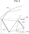
- FIG. 8 is a schematic diagram illustrating a projector of a head-up display which is disclosed in PTL 1.
- projector 300 which projects an image and windshield glass 101 that is a display medium to which an image from projector 300 is projected are illustrated.
- the image to be projected by projector 300 may be light configuring an image.
- windshield glass 101 may be a front glass, for example.
- projector 300 includes first mirror 301, second mirror 302, and display 303.
- Display 303 illustrated in FIG. 8 is an image generator which generates an image to be projected from projector 300.
- Display 303 is configured by a liquid crystal panel or the like, for example.
- Second mirror 302 illustrated in FIG. 8 is a mirror configuring an optical system of projector 300 and reflects the image incident from display 303 toward first mirror 301.
- First mirror 301 illustrated in FIG. 8 is a mirror configuring an optical system of projector 300 and reflects the image incident from second mirror 302 toward windshield glass 101.
- the display image to be recognized is a virtual image, for example.
- the horizontal direction of the display image is a direction perpendicular to a sheet surface of FIG. 8 .
- the vertical direction is a top and bottom direction of FIG. 8 .
- the enlargement of the dimension in the vertical direction of the display image is further limited than the enlargement of the dimension in the horizontal direction.
- each of the exemplary embodiments described below shows a general example or specific example of the present disclosure.
- the numerical values, shapes, materials, structural elements, the disposition and connection form of the structural elements, steps, the processing order of the steps or the like, shown in the following exemplary embodiments are mere examples and do not restrict the scope of the present disclosure.
- structural elements not recited in the independent claims each indicating the top concept are described as arbitrary structural elements.
- FIGS. 1 and 2 A configuration of the display device according to the present exemplary embodiment will be described using FIGS. 1 and 2 .
- FIG. 1 is a block diagram illustrating a functional configuration of a display device according to the present exemplary embodiment.
- FIG. 2 is a schematic diagram illustrating a disposition example of the display device in a vehicle of the present exemplary embodiment.
- display device 1 includes projector 10, controller 20, and acquisition unit 30.
- Display device 1 illustrated in FIG. 1 is a so-called head-up display and is provided in a vehicle interior as illustrated in FIG. 2 .
- Display device 1 projects an image to windshield glass 101 and causes user 200 to visually recognize the reflected image in windshield glass 101.
- Projector 10 illustrated in FIGS. 1 and 2 is an image projection device which can project an image.
- Projector 10 is the image projection device which has an optical system therein and is provided in the inside the dashboard of the vehicle as illustrated in FIG. 2 . A detailed configuration of the inner portion of projector 10 will be described later.
- Projector 10 projects light toward windshield glass 101 that is a display medium with translucency and is capable of forming an image to position 80 using the reflection in windshield glass 101.
- the image formed is a virtual image, for example.
- Acquisition unit 30 illustrated in FIG. 1 acquires information relating to the vehicle from the vehicle.
- the information relating to the vehicle is speed information or the like, specifically.
- Acquisition unit 30 may acquire the information from a device different from display device 1 such as a smartphone, a car navigation device provided in a vehicle, or the like.
- a communication network such as a wired or wireless communication network may be used.
- the communication network may be a communication interface.
- Controller 20 illustrated in FIG. 1 is a processor for adjusting the image to be projected to projector 10 in accordance with the information acquired by acquisition unit 30.
- controller 20 projects an image including an arrow for a navigation, an image including a speedometer, or the like based on the information acquired by acquisition unit 30.
- controller 20 is a processor. Controller 20 may be configured by only hardware and may be implemented by a combination of the hardware and the software. For example, controller 20 can be implemented by a microcomputer or the like.
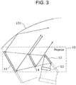
- FIG. 3 is a schematic diagram illustrating an internal configuration of projector 10 according to the present exemplary embodiment.
- projector 10 which projects an image and windshield glass 101 that is a display medium to which an image from projector 10 is projected are illustrated.
- the image to be projected by projector 10 may be light configuring an image.
- projector 10 includes first mirror 11, second mirror 12, display 13, and beam splitter 14.
- Display 13 illustrated in FIG. 3 is an image generator which generates an image to be projected from projector 10.
- Display 13 is configured by a liquid crystal panel or the like, for example.
- display 13 alternately emits a first image to be reflected to first mirror 11 and a second image to be reflected to beam splitter 14.
- the first image and the second image may be light configuring the image.
- Second mirror 12 illustrated in FIG. 3 is a mirror configuring an optical system of projector 10 and reflects the image incident from display 13 toward beam splitter 14.
- Second mirror 12 may be a plane mirror and may have a curvature radius or a curved shape in accordance with an optical magnification, a divergence angle of the light configuring the image emitted from display 13, a shape of the other optical element of projector 10, or the like.
- As a material configuring a reflection surface of second mirror 12 an arbitrary material which can reflect the image incident from display 13 can be used.
- Beam splitter 14 illustrated in FIG. 3 is an optical element configuring the optical system of projector 10 and transmits the first image among the images incident from second mirror 12 and reflects the second image toward windshield glass 101.
- beam splitter 14 uses an optical switch which is capable of switching the transmission and the reflection of the image.
- the optical switch for example, a switchable hologram which is capable of switching the transmission and the reflection by an applied voltage can be used.
- the reflectance and the transmittance of beam splitter 14 can be switched at a timing at which the first image is transmitted and the second image is reflected.
- First mirror 11 illustrated in FIG. 3 is a mirror configuring an optical system of projector 10, allows the image which has passed through beam splitter 14 to incident, and reflects the incident image toward windshield glass 101.
- First mirror 11 may be a plane mirror and may be a concave mirror.
- an element which has the light-converging ability with respect to the reflected light and does not have the light-converging ability with respect to the transmitted light may be used.
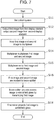
- FIG. 4 is a flow chart illustrating an outline of an operation of display device 1.
- the optical system of projector 10 is set on a predetermined position (S1).
- first mirror 11, second mirror 12, and beam splitter 14 are included in the optical system.
- image information to be displayed is output from controller 20 to display 13 and an image is emitted from display 13 toward second mirror 12 based on the image information (S2).
- image information information for generating the first image and the second image is included, and in the image emitted by display 13, the first image and the second image are included.
- display 13 alternatively emits the first image and the second image at the different timings.
- second mirror 12 reflects the image incident from display 13 toward beam splitter 14 (S3).
- the image is incident to beam splitter 14 (S4).
- beam splitter 14 When the image is incident to beam splitter 14, if it is a timing when the first image is incident (Yes in S5), beam splitter 14, of which the transmittance is increased by controller 20, causes the first image to pass therethrough (S6). The first image which has passed through beam splitter 14 is incident to first mirror 11 and the incident first image is projected to windshield glass 101 by being reflected by first mirror 11 (S7). On the other hand, if it is not a timing when the first image is incident to beam splitter 14 (No in S5), beam splitter 14, of which the reflectance is increased by controller 20, reflects the second image to windshield glass 101. Therefore, the second image is projected to windshield glass 101 (S8).
- the image emitted from display 13 is separated into the first image and the second image and the images are projected on windshield glass 101 from first mirror 11 and beam splitter 14, respectively. Accordingly, by projecting the first image and the second image to the different regions on windshield glass 101, the dimension of the display image to be visually recognized by user 200 in the vertical direction can be enlarged. Furthermore, in the present exemplary embodiment, since light paths of the first image and the second image are partially shared, the enlargement of the optical system can be suppressed.
- the first image and the second image may be alternatively switched at a high speed by display 13. Therefore, the eyes of user 200 can recognize the first image and the second image such that they are displayed at the same time.
- second mirror 12 may not be used. That is, the image emitted from display 13 may directly incident to beam splitter 14. Therefore, the optical system can be simplified.
- Exemplary Embodiment 1 As a configuration in which the first image and the second image are incident to the beam splitter at the different timings, the first image and the second image are separated. Whereas, in the present exemplary embodiment, by using the first image and the second image which have the different spectra, the first image and the second image are separated. Since the present exemplary embodiment is mainly different from Exemplary Embodiment 1 in terms of the configuration of the projector, the projector will be described below and the other configuration will not be described.
- FIG. 5 is a schematic diagram illustrating an internal configuration of projector 10a according to the present exemplary embodiment.
- projector 10a includes first mirror 11, display 13a, and beam splitter 14a.
- Display 13a illustrated in FIG. 5 is an image generator which generates an image to be projected from projector 10a. As illustrated in FIG. 5 , display 13a includes first display element 131a and second display element 131b, first light source 132a and second light source 132b, and multiplexer 133.
- first light source 132a and second light source 132b of display 13a is a light source which outputs light to first display element 131a and second display element 131b.
- first light source 132a and second light source 132b have the different spectra.
- First light source 132a is a light source which outputs blue light of wavelength B1, green light of wavelength G1, and red light of wavelength R1, mainly.
- second light source 132b is a light source which outputs blue light of wavelength B2 ( ⁇ B1), green light of wavelength G2 ( ⁇ G1), and red light of wavelength R2 ( ⁇ G1), mainly.
- As light sources for example, a light source which is obtained by combining a semiconductor laser element which outputs laser beam of each wavelength and a solid-state laser element.
- First display element 131a and second display element 131b of display 13a are configured by a liquid crystal panel, for example.
- first display element 131a outputs the first image to be reflected by first mirror 11 and second display element 131b outputs the second image to be reflected by beam splitter 14a.
- the first image and the second image may be light configuring the image.
- Multiplexer 133 of display 13a is an optical element which multiplexes the first image input from first display element 131a and the second image input from second display element 131b to emit the images toward beam splitter 14a.
- reflection wavelength characteristics of multiplexer 133 will be described using FIG. 6 .
- FIG. 6 is a diagram illustrating an outline of reflection wavelength characteristics of multiplexer 133.
- multiplexer 133 has high reflectance in the wavelength band of the light output from second light source 132b and second display element 131b and has low reflectance in the wavelength band of the light output from first light source 132a and first display element 131a. Therefore, multiplexer 133 reflects only second image emitted from second display element 131b. In addition, in this case, multiplexer 133 deflects a travelling direction of the second image at an angle of 90 degrees. Therefore, multiplexer 133 can multiplex and output the first image and the second image. Multiplexer 133 having such characteristics can be implemented by using a hologram, for example.
- Beam splitter 14a illustrated in FIG. 5 is an optical element which allows the first image among the first image and the second image emitted from multiplexer 133 to pass through thereto and the second image to reflect toward windshield glass 101.
- beam splitter 14a is configured by an optical element having the same reflection wavelength characteristics as that of multiplexer 133 illustrated in FIG. 6 . Accordingly, as beam splitter 14a, the optical element which is the same as that of multiplexer 133 may be used, for example.
- first mirror 11 illustrated in FIG. 5 is the same as that of projector 10 of Exemplary Embodiment 1, the description will not be described.
- FIG. 7 is a flow chart illustrating an outline of an operation of the display device according to the present exemplary embodiment.
- the optical system of projector 10a is set on a predetermined position (S11).
- the optical system includes first mirror 11 and beam splitter 14a.
- First light source 132a and second light source 132b, and first display element 131a and second display element 131b are driven based on the information and each of the first image and the second image is output from first display element 131a and second display element 131b (S12).
- first image output from first display element 131a and the second image output from second display element 131b are input to multiplexer 133 (S13) and multiplexed by multiplexer 133 (S14), and then emitted toward beam splitter 14a (S15).
- the first image and the second image are incident to beam splitter 14a (S16).
- Beam splitter 14a allows the first image to pass through thereto among the incident images and projects the second image to windshield glass 101 by reflecting the second image (S17).
- the first image which has passed through beam splitter 14a is incident to first mirror 11 and projected to windshield glass 101 by being reflected by first mirror 11 (S18).
- the first image and the second image emitted from display 13a are separated by beam splitter 14a, and the first image and the second image are projected on windshield glass 101 from first mirror 11 and beam splitter 14a, respectively. Accordingly, by setting the projecting region to windshield glass 101 of the first image and the second image to the different regions, the dimension of the display image to be visually recognized by user 200 in the vertical direction can be enlarged. Furthermore, in the present exemplary embodiment, since light paths of the first image and the second image are partially shared, the enlargement of the optical system can be suppressed.
- the first image and the second image can be displayed at the same time.
- the first image and the second image are mainly configured by light of three wavelength bands so as to be a color image.
- the spectrum included in each image is not limited thereto.
- the images may be configured by the different light beams of one different wavelength band.
- a configuration in which a second mirror which is used in Exemplary Embodiment 1 is not used is shown.
- the second mirror may be provided between display 13a and beam splitter 14a in the present exemplary embodiment. Therefore, a free degree of a design of an optical system is improved.
- a configuration in which as the display medium with translucency for projecting the first image and the second image, windshield glass 101 is used, is shown.
- the configuration is not limited thereto.
- one or more combiner can be used.
- the first image and the second image can be displayed by adjacent and displayed in isolation.
- the first image adjacent to the lower end of windshield glass 101 and the second image adjacent to the upper end may be projected, respectively. Therefore, it is possible to suppress blocking a view filed in front of user 200.
- a configuration in which the first image and the second image are formed by light beams which have different spectra to each other is shown.
- a polarization beam splitter can be used as the multiplexer and the beam splitter.
- any of a two-dimensional image and a three-dimensional image can be used, respectively.
- the display device may be provided in transportation equipment other than the vehicle.
- the transportation equipment includes aircraft, a ship, or the like.
- Each of the structural elements in each of the above-described exemplary embodiments may be configured in the form of an exclusive hardware product, or may be realized by executing a software program suitable for the structural element.
- the constituent elements may be implemented by a program execution unit such as a CPU or a processor which reads and executes a software program recorded on a recording medium such as a hard disk or a semiconductor memory.
- a display device and a display method according to one or more aspects of the present invention have been thus described on the basis of Exemplary Embodiment 1 and Exemplary Embodiment 2.
- the present disclosure is not limited to the exemplary embodiments. Modifications of the embodiments which would occur to those skilled in the art are applied to the exemplary embodiments, or embodiments configured by combining constituent elements in other different embodiments, are also within the scope of the one or more aspects of the present invention, without departing from the spirit of the present invention.
- a process to be executed by a specified processor may be executed by the other processor.
- a sequence of a plurality of processes may be changed and a plurality of processes may be concurrently performed.
- the display device includes a display, a beam splitter, and a first mirror.
- the display emits a first image and a second image.
- the first image and the second image emitted from the display are incident to the beam splitter.
- the beam splitter projects the images to a display medium by transmitting the incident first image and reflecting the incident second image.
- the first image which has passed through the beam splitter is incident to the first mirror.
- the first mirror projects the incident first image to the display medium by reflecting the incident first image.
- first image and the second image may be projected to different regions on the display medium.
- a second mirror that reflects the first image and the second image emitted from the display toward the beam splitter may further be included.
- the display may include a first display element that outputs the first image, a second display element that outputs the second image, and a multiplexer.
- the multiplexer multiplexes the first image output from the first display element and the second image output from the second display element and then emitts the multiplexed images.
- the first mirror may have light-converging ability.
- the beam splitter may have the light-converging ability with respect to reflected light and may not have the light-converging ability with respect to transmitted light.
- first image and the second image are emitted from the display at the different timings to each other, and reflectance of the beam splitter may be switched such that the first image is transmitted and the second image is reflected.
- the first image and the second image have different optical wavelength distributions to each other, and the beam splitter may include a wavelength selection mirror.
- the wavelength selection mirror may include a hologram.
- the first image and the second image are formed by light beams having different directions of polarization
- the beam splitter may include a polarization beam splitter.
- a display method is a display method of a display device including a display and a first mirror.
- a beam splitter is proved in the display device.
- the first image and the second image are emitted by the display and the first image and the second image emitted from the display is incident to the beam splitter.
- the images are projected to a display medium by transmitting the first image by the beam splitter and reflecting the second image by the beam splitter.
- the images are projected to the display medium by making the first image which has passed through the beam splitter incident to the first mirror and reflecting the incident first image to the first mirror.
- general or specific aspects of the above may be realized by a system, an apparatus, an integrated circuit, a computer program, or a recording medium.
- general or specific aspects of the above may be realized by an arbitrary combination of a system, an apparatus, an integrated circuit, a computer program, and a recording medium.
- the present disclosure is useful as a head-up display.
Landscapes
- Engineering & Computer Science (AREA)
- Physics & Mathematics (AREA)
- General Physics & Mathematics (AREA)
- Theoretical Computer Science (AREA)
- Optics & Photonics (AREA)
- Computer Hardware Design (AREA)
- Chemical & Material Sciences (AREA)
- Combustion & Propulsion (AREA)
- Transportation (AREA)
- Mechanical Engineering (AREA)
- Educational Technology (AREA)
- Educational Administration (AREA)
- Business, Economics & Management (AREA)
- Aviation & Aerospace Engineering (AREA)
- Crystallography & Structural Chemistry (AREA)
- Instrument Panels (AREA)
- Controls And Circuits For Display Device (AREA)
Applications Claiming Priority (2)
| Application Number | Priority Date | Filing Date | Title |
|---|---|---|---|
| JP2014098925A JP6238072B2 (ja) | 2014-05-12 | 2014-05-12 | 表示装置及びその表示方法 |
| PCT/JP2015/002334 WO2015174048A1 (fr) | 2014-05-12 | 2015-05-08 | Dispositif d'affichage et son procédé d'affichage |
Publications (3)
| Publication Number | Publication Date |
|---|---|
| EP3144716A1 true EP3144716A1 (fr) | 2017-03-22 |
| EP3144716A4 EP3144716A4 (fr) | 2017-09-27 |
| EP3144716B1 EP3144716B1 (fr) | 2020-02-26 |
Family
ID=54479599
Family Applications (1)
| Application Number | Title | Priority Date | Filing Date |
|---|---|---|---|
| EP15792724.5A Active EP3144716B1 (fr) | 2014-05-12 | 2015-05-08 | Dispositif d'affichage et son procédé d'affichage |
Country Status (4)
| Country | Link |
|---|---|
| US (1) | US9927610B2 (fr) |
| EP (1) | EP3144716B1 (fr) |
| JP (1) | JP6238072B2 (fr) |
| WO (1) | WO2015174048A1 (fr) |
Cited By (3)
| Publication number | Priority date | Publication date | Assignee | Title |
|---|---|---|---|---|
| FR3076913A1 (fr) * | 2018-01-17 | 2019-07-19 | Valeo Comfort And Driving Assistance | Afficheur tete-haute pour vehicule automobile et systeme d'aide a la conduite comportant un tel afficheur |
| EP3465330A4 (fr) * | 2016-05-23 | 2020-03-04 | LG Electronics Inc. -1- | Affichage tête haute pour véhicule |
| EP3608703A4 (fr) * | 2017-04-06 | 2020-12-23 | LG Electronics Inc. -1- | Appareil d'affichage tête haute pour véhicule |
Families Citing this family (10)
| Publication number | Priority date | Publication date | Assignee | Title |
|---|---|---|---|---|
| CN105824123A (zh) * | 2016-05-13 | 2016-08-03 | 深圳中科呼图信息技术有限公司 | 一种增强现实头戴装置 |
| KR101928139B1 (ko) * | 2016-06-16 | 2018-12-11 | 한양대학교 산학협력단 | 헤드업 디스플레이 장치 |
| FR3054327B1 (fr) * | 2016-07-22 | 2021-01-01 | Valeo Comfort & Driving Assistance | Afficheur tete-haute |
| KR101899981B1 (ko) | 2016-12-02 | 2018-09-19 | 엘지전자 주식회사 | 차량용 헤드 업 디스플레이 |
| CN108656952B (zh) * | 2017-04-01 | 2021-02-09 | 宁波舜宇车载光学技术有限公司 | 车载信息显示装置、车载信息显示方法和交通运输工具 |
| TWM567693U (zh) * | 2018-01-18 | 2018-10-01 | 禾龍有限公司 | 能快速安全更換及穩固定位刀片之刀具及其刀柄結構 |
| US11320901B2 (en) | 2018-05-31 | 2022-05-03 | Boe Technology Group Co., Ltd. | Head-up display system and display method, vehicle, head-up display device, and computer-readable storage medium |
| DE102020103824A1 (de) | 2020-02-13 | 2021-08-19 | Bayerische Motoren Werke Aktiengesellschaft | Projektionseinheit für eine Blickfeldanzeigevorrichtung in einem Fahrzeug |
| CN114063290A (zh) * | 2020-08-07 | 2022-02-18 | 东莞创奕电子科技有限公司 | 车用抬头显示系统 |
| US20220055479A1 (en) * | 2020-08-24 | 2022-02-24 | Conserve & Associates , Inc. | Vehicular head-up display system with virtual images in different distances |
Family Cites Families (12)
| Publication number | Priority date | Publication date | Assignee | Title |
|---|---|---|---|---|
| US4987410A (en) * | 1988-01-25 | 1991-01-22 | Kaiser Aerospace & Electronics Corporation | Multiple image forming apparatus |
| IL88931A (en) * | 1988-01-25 | 1992-05-25 | Kaiser Aerospace & Electronics | Multiple image-forming apparatus |
| JP3651808B2 (ja) * | 1993-12-08 | 2005-05-25 | 大日本印刷株式会社 | カラーリップマンホログラムの製造方法 |
| JP4731938B2 (ja) * | 2004-05-13 | 2011-07-27 | 株式会社リコー | 画像表示装置・投射光学系 |
| JP2005338689A (ja) * | 2004-05-31 | 2005-12-08 | Nippon Seiki Co Ltd | 反射ミラー及びその反射ミラーを備えた反射ミラー装置 |
| TWI311232B (en) * | 2006-10-05 | 2009-06-21 | Delta Electronics Inc | Light processing structure for a digital light processing projection device |
| US8711485B2 (en) | 2008-11-05 | 2014-04-29 | Johnson Controls Technology Company | Vehicle display system or projection display for a motor vehicle, and calibration method |
| US20100231868A1 (en) * | 2009-03-13 | 2010-09-16 | Alvis Technologies Inc. | Display device |
| JP2010276689A (ja) * | 2009-05-26 | 2010-12-09 | Nippon Seiki Co Ltd | ヘッドアップディスプレイ装置 |
| JP2012163705A (ja) | 2011-02-04 | 2012-08-30 | Denso Corp | ヘッドアップディスプレイ装置 |
| CN103728821B (zh) | 2012-10-12 | 2015-10-28 | 扬明光学股份有限公司 | 投影装置 |
| EP3133437A4 (fr) | 2014-04-14 | 2017-03-22 | Panasonic Intellectual Property Management Co., Ltd. | Affichage tête haute et corps mobile équipé d'un affichage tête haute |
-
2014
- 2014-05-12 JP JP2014098925A patent/JP6238072B2/ja active Active
-
2015
- 2015-05-08 US US15/308,357 patent/US9927610B2/en active Active
- 2015-05-08 WO PCT/JP2015/002334 patent/WO2015174048A1/fr active Application Filing
- 2015-05-08 EP EP15792724.5A patent/EP3144716B1/fr active Active
Cited By (5)
| Publication number | Priority date | Publication date | Assignee | Title |
|---|---|---|---|---|
| EP3465330A4 (fr) * | 2016-05-23 | 2020-03-04 | LG Electronics Inc. -1- | Affichage tête haute pour véhicule |
| EP3608703A4 (fr) * | 2017-04-06 | 2020-12-23 | LG Electronics Inc. -1- | Appareil d'affichage tête haute pour véhicule |
| US11237391B2 (en) | 2017-04-06 | 2022-02-01 | Lg Electronics Inc. | Head-up display device for vehicle |
| FR3076913A1 (fr) * | 2018-01-17 | 2019-07-19 | Valeo Comfort And Driving Assistance | Afficheur tete-haute pour vehicule automobile et systeme d'aide a la conduite comportant un tel afficheur |
| WO2019141788A1 (fr) * | 2018-01-17 | 2019-07-25 | Valeo Comfort And Driving Assistance | Afficheur tete-haute pour vehicule automobile et systeme d'aide a la conduite comportant un tel afficheur |
Also Published As
| Publication number | Publication date |
|---|---|
| JP2015215515A (ja) | 2015-12-03 |
| EP3144716B1 (fr) | 2020-02-26 |
| WO2015174048A1 (fr) | 2015-11-19 |
| US9927610B2 (en) | 2018-03-27 |
| JP6238072B2 (ja) | 2017-11-29 |
| EP3144716A4 (fr) | 2017-09-27 |
| US20170059863A1 (en) | 2017-03-02 |
Similar Documents
| Publication | Publication Date | Title |
|---|---|---|
| EP3144716B1 (fr) | Dispositif d'affichage et son procédé d'affichage | |
| JP6603883B2 (ja) | ヘッドアップディスプレイ、およびヘッドアップディスプレイを搭載した移動体 | |
| JP6597196B2 (ja) | 虚像表示措置 | |
| JP6473895B2 (ja) | ヘッドアップディスプレイ、およびヘッドアップディスプレイを搭載した移動体 | |
| JP5214060B1 (ja) | 虚像表示装置 | |
| JP6489371B2 (ja) | 表示装置 | |
| JP2016520869A (ja) | マルチ開口投射型ディスプレイおよびそのための単一像生成器 | |
| JP6601431B2 (ja) | ヘッドアップディスプレイ装置 | |
| JP2010019874A (ja) | 表示装置 | |
| CN115397692B (zh) | 显示装置 | |
| EP2728394A1 (fr) | Dispositif d'affichage | |
| CN113661432B (zh) | 平视显示装置 | |
| JP2011064902A (ja) | 表示装置及び表示方法 | |
| US20180284436A1 (en) | Head-up display device | |
| JP2018146950A (ja) | 表示装置及び機器 | |
| JP2021120750A (ja) | 車載用表示装置 | |
| EP3816700A1 (fr) | Affichage tête haute et corps mobile sur lequel est monté un affichage tête haute | |
| JP2016099477A (ja) | 投影装置、投影方法、プログラムおよび記憶媒体 | |
| JP7111070B2 (ja) | ヘッドアップディスプレイ装置 | |
| JP2015219389A (ja) | 虚像表示装置及び画像形成素子 | |
| US20230305298A1 (en) | Waveguide Display Assembly for a 3D Head-up Display Device in a Vehicle, and Method for Operating Same | |
| US20230014232A1 (en) | Image displaying device | |
| JP2016085387A (ja) | 表示装置 | |
| JP2018010251A (ja) | 虚像表示装置 | |
| JP2010032615A (ja) | 表示装置 |
Legal Events
| Date | Code | Title | Description |
|---|---|---|---|
| STAA | Information on the status of an ep patent application or granted ep patent |
Free format text: STATUS: THE INTERNATIONAL PUBLICATION HAS BEEN MADE |
|
| PUAI | Public reference made under article 153(3) epc to a published international application that has entered the european phase |
Free format text: ORIGINAL CODE: 0009012 |
|
| STAA | Information on the status of an ep patent application or granted ep patent |
Free format text: STATUS: REQUEST FOR EXAMINATION WAS MADE |
|
| 17P | Request for examination filed |
Effective date: 20161026 |
|
| AK | Designated contracting states |
Kind code of ref document: A1 Designated state(s): AL AT BE BG CH CY CZ DE DK EE ES FI FR GB GR HR HU IE IS IT LI LT LU LV MC MK MT NL NO PL PT RO RS SE SI SK SM TR |
|
| AX | Request for extension of the european patent |
Extension state: BA ME |
|
| DAV | Request for validation of the european patent (deleted) | ||
| DAX | Request for extension of the european patent (deleted) | ||
| A4 | Supplementary search report drawn up and despatched |
Effective date: 20170829 |
|
| RIC1 | Information provided on ipc code assigned before grant |
Ipc: G02F 1/1347 20060101ALN20170823BHEP Ipc: G09B 9/32 20060101ALI20170823BHEP Ipc: G02B 27/01 20060101AFI20170823BHEP Ipc: G02B 5/30 20060101ALI20170823BHEP Ipc: G09G 5/00 20060101ALI20170823BHEP Ipc: G09G 3/20 20060101ALI20170823BHEP Ipc: G02F 1/1335 20060101ALN20170823BHEP Ipc: G09G 3/00 20060101ALI20170823BHEP Ipc: B60K 35/00 20060101ALI20170823BHEP |
|
| RIC1 | Information provided on ipc code assigned before grant |
Ipc: G09G 3/20 20060101ALI20190913BHEP Ipc: G02B 27/01 20060101AFI20190913BHEP Ipc: G02F 1/1335 20060101ALN20190913BHEP Ipc: G09G 5/00 20060101ALI20190913BHEP Ipc: B60K 35/00 20060101ALI20190913BHEP Ipc: G02B 5/30 20060101ALI20190913BHEP Ipc: G02F 1/1347 20060101ALN20190913BHEP Ipc: G09G 3/00 20060101ALI20190913BHEP Ipc: G09B 9/32 20060101ALI20190913BHEP |
|
| GRAP | Despatch of communication of intention to grant a patent |
Free format text: ORIGINAL CODE: EPIDOSNIGR1 |
|
| STAA | Information on the status of an ep patent application or granted ep patent |
Free format text: STATUS: GRANT OF PATENT IS INTENDED |
|
| RIC1 | Information provided on ipc code assigned before grant |
Ipc: B60K 35/00 20060101ALI20190930BHEP Ipc: G02B 5/30 20060101ALI20190930BHEP Ipc: G09G 3/00 20060101ALI20190930BHEP Ipc: G09B 9/32 20060101ALI20190930BHEP Ipc: G02F 1/1347 20060101ALN20190930BHEP Ipc: G02B 27/01 20060101AFI20190930BHEP Ipc: G02F 1/1335 20060101ALN20190930BHEP Ipc: G09G 5/00 20060101ALI20190930BHEP Ipc: G09G 3/20 20060101ALI20190930BHEP |
|
| INTG | Intention to grant announced |
Effective date: 20191104 |
|
| GRAS | Grant fee paid |
Free format text: ORIGINAL CODE: EPIDOSNIGR3 |
|
| GRAA | (expected) grant |
Free format text: ORIGINAL CODE: 0009210 |
|
| STAA | Information on the status of an ep patent application or granted ep patent |
Free format text: STATUS: THE PATENT HAS BEEN GRANTED |
|
| AK | Designated contracting states |
Kind code of ref document: B1 Designated state(s): AL AT BE BG CH CY CZ DE DK EE ES FI FR GB GR HR HU IE IS IT LI LT LU LV MC MK MT NL NO PL PT RO RS SE SI SK SM TR |
|
| REG | Reference to a national code |
Ref country code: GB Ref legal event code: FG4D |
|
| REG | Reference to a national code |
Ref country code: CH Ref legal event code: EP |
|
| REG | Reference to a national code |
Ref country code: AT Ref legal event code: REF Ref document number: 1238359 Country of ref document: AT Kind code of ref document: T Effective date: 20200315 |
|
| REG | Reference to a national code |
Ref country code: IE Ref legal event code: FG4D |
|
| REG | Reference to a national code |
Ref country code: DE Ref legal event code: R096 Ref document number: 602015047789 Country of ref document: DE |
|
| PG25 | Lapsed in a contracting state [announced via postgrant information from national office to epo] |
Ref country code: NO Free format text: LAPSE BECAUSE OF FAILURE TO SUBMIT A TRANSLATION OF THE DESCRIPTION OR TO PAY THE FEE WITHIN THE PRESCRIBED TIME-LIMIT Effective date: 20200526 Ref country code: RS Free format text: LAPSE BECAUSE OF FAILURE TO SUBMIT A TRANSLATION OF THE DESCRIPTION OR TO PAY THE FEE WITHIN THE PRESCRIBED TIME-LIMIT Effective date: 20200226 Ref country code: FI Free format text: LAPSE BECAUSE OF FAILURE TO SUBMIT A TRANSLATION OF THE DESCRIPTION OR TO PAY THE FEE WITHIN THE PRESCRIBED TIME-LIMIT Effective date: 20200226 |
|
| REG | Reference to a national code |
Ref country code: NL Ref legal event code: MP Effective date: 20200226 |
|
| REG | Reference to a national code |
Ref country code: LT Ref legal event code: MG4D |
|
| PG25 | Lapsed in a contracting state [announced via postgrant information from national office to epo] |
Ref country code: HR Free format text: LAPSE BECAUSE OF FAILURE TO SUBMIT A TRANSLATION OF THE DESCRIPTION OR TO PAY THE FEE WITHIN THE PRESCRIBED TIME-LIMIT Effective date: 20200226 Ref country code: GR Free format text: LAPSE BECAUSE OF FAILURE TO SUBMIT A TRANSLATION OF THE DESCRIPTION OR TO PAY THE FEE WITHIN THE PRESCRIBED TIME-LIMIT Effective date: 20200527 Ref country code: IS Free format text: LAPSE BECAUSE OF FAILURE TO SUBMIT A TRANSLATION OF THE DESCRIPTION OR TO PAY THE FEE WITHIN THE PRESCRIBED TIME-LIMIT Effective date: 20200626 Ref country code: BG Free format text: LAPSE BECAUSE OF FAILURE TO SUBMIT A TRANSLATION OF THE DESCRIPTION OR TO PAY THE FEE WITHIN THE PRESCRIBED TIME-LIMIT Effective date: 20200526 Ref country code: LV Free format text: LAPSE BECAUSE OF FAILURE TO SUBMIT A TRANSLATION OF THE DESCRIPTION OR TO PAY THE FEE WITHIN THE PRESCRIBED TIME-LIMIT Effective date: 20200226 Ref country code: SE Free format text: LAPSE BECAUSE OF FAILURE TO SUBMIT A TRANSLATION OF THE DESCRIPTION OR TO PAY THE FEE WITHIN THE PRESCRIBED TIME-LIMIT Effective date: 20200226 |
|
| PG25 | Lapsed in a contracting state [announced via postgrant information from national office to epo] |
Ref country code: NL Free format text: LAPSE BECAUSE OF FAILURE TO SUBMIT A TRANSLATION OF THE DESCRIPTION OR TO PAY THE FEE WITHIN THE PRESCRIBED TIME-LIMIT Effective date: 20200226 |
|
| PG25 | Lapsed in a contracting state [announced via postgrant information from national office to epo] |
Ref country code: CZ Free format text: LAPSE BECAUSE OF FAILURE TO SUBMIT A TRANSLATION OF THE DESCRIPTION OR TO PAY THE FEE WITHIN THE PRESCRIBED TIME-LIMIT Effective date: 20200226 Ref country code: RO Free format text: LAPSE BECAUSE OF FAILURE TO SUBMIT A TRANSLATION OF THE DESCRIPTION OR TO PAY THE FEE WITHIN THE PRESCRIBED TIME-LIMIT Effective date: 20200226 Ref country code: SM Free format text: LAPSE BECAUSE OF FAILURE TO SUBMIT A TRANSLATION OF THE DESCRIPTION OR TO PAY THE FEE WITHIN THE PRESCRIBED TIME-LIMIT Effective date: 20200226 Ref country code: EE Free format text: LAPSE BECAUSE OF FAILURE TO SUBMIT A TRANSLATION OF THE DESCRIPTION OR TO PAY THE FEE WITHIN THE PRESCRIBED TIME-LIMIT Effective date: 20200226 Ref country code: DK Free format text: LAPSE BECAUSE OF FAILURE TO SUBMIT A TRANSLATION OF THE DESCRIPTION OR TO PAY THE FEE WITHIN THE PRESCRIBED TIME-LIMIT Effective date: 20200226 Ref country code: PT Free format text: LAPSE BECAUSE OF FAILURE TO SUBMIT A TRANSLATION OF THE DESCRIPTION OR TO PAY THE FEE WITHIN THE PRESCRIBED TIME-LIMIT Effective date: 20200719 Ref country code: LT Free format text: LAPSE BECAUSE OF FAILURE TO SUBMIT A TRANSLATION OF THE DESCRIPTION OR TO PAY THE FEE WITHIN THE PRESCRIBED TIME-LIMIT Effective date: 20200226 Ref country code: ES Free format text: LAPSE BECAUSE OF FAILURE TO SUBMIT A TRANSLATION OF THE DESCRIPTION OR TO PAY THE FEE WITHIN THE PRESCRIBED TIME-LIMIT Effective date: 20200226 Ref country code: SK Free format text: LAPSE BECAUSE OF FAILURE TO SUBMIT A TRANSLATION OF THE DESCRIPTION OR TO PAY THE FEE WITHIN THE PRESCRIBED TIME-LIMIT Effective date: 20200226 |
|
| REG | Reference to a national code |
Ref country code: AT Ref legal event code: MK05 Ref document number: 1238359 Country of ref document: AT Kind code of ref document: T Effective date: 20200226 |
|
| REG | Reference to a national code |
Ref country code: DE Ref legal event code: R097 Ref document number: 602015047789 Country of ref document: DE |
|
| PLBE | No opposition filed within time limit |
Free format text: ORIGINAL CODE: 0009261 |
|
| STAA | Information on the status of an ep patent application or granted ep patent |
Free format text: STATUS: NO OPPOSITION FILED WITHIN TIME LIMIT |
|
| PG25 | Lapsed in a contracting state [announced via postgrant information from national office to epo] |
Ref country code: LI Free format text: LAPSE BECAUSE OF NON-PAYMENT OF DUE FEES Effective date: 20200531 Ref country code: AT Free format text: LAPSE BECAUSE OF FAILURE TO SUBMIT A TRANSLATION OF THE DESCRIPTION OR TO PAY THE FEE WITHIN THE PRESCRIBED TIME-LIMIT Effective date: 20200226 Ref country code: CH Free format text: LAPSE BECAUSE OF NON-PAYMENT OF DUE FEES Effective date: 20200531 Ref country code: IT Free format text: LAPSE BECAUSE OF FAILURE TO SUBMIT A TRANSLATION OF THE DESCRIPTION OR TO PAY THE FEE WITHIN THE PRESCRIBED TIME-LIMIT Effective date: 20200226 Ref country code: MC Free format text: LAPSE BECAUSE OF FAILURE TO SUBMIT A TRANSLATION OF THE DESCRIPTION OR TO PAY THE FEE WITHIN THE PRESCRIBED TIME-LIMIT Effective date: 20200226 |
|
| 26N | No opposition filed |
Effective date: 20201127 |
|
| PG25 | Lapsed in a contracting state [announced via postgrant information from national office to epo] |
Ref country code: PL Free format text: LAPSE BECAUSE OF FAILURE TO SUBMIT A TRANSLATION OF THE DESCRIPTION OR TO PAY THE FEE WITHIN THE PRESCRIBED TIME-LIMIT Effective date: 20200226 Ref country code: SI Free format text: LAPSE BECAUSE OF FAILURE TO SUBMIT A TRANSLATION OF THE DESCRIPTION OR TO PAY THE FEE WITHIN THE PRESCRIBED TIME-LIMIT Effective date: 20200226 |
|
| REG | Reference to a national code |
Ref country code: BE Ref legal event code: MM Effective date: 20200531 |
|
| GBPC | Gb: european patent ceased through non-payment of renewal fee |
Effective date: 20200526 |
|
| PG25 | Lapsed in a contracting state [announced via postgrant information from national office to epo] |
Ref country code: LU Free format text: LAPSE BECAUSE OF NON-PAYMENT OF DUE FEES Effective date: 20200508 |
|
| PG25 | Lapsed in a contracting state [announced via postgrant information from national office to epo] |
Ref country code: IE Free format text: LAPSE BECAUSE OF NON-PAYMENT OF DUE FEES Effective date: 20200508 Ref country code: GB Free format text: LAPSE BECAUSE OF NON-PAYMENT OF DUE FEES Effective date: 20200526 Ref country code: FR Free format text: LAPSE BECAUSE OF NON-PAYMENT OF DUE FEES Effective date: 20200531 |
|
| PG25 | Lapsed in a contracting state [announced via postgrant information from national office to epo] |
Ref country code: BE Free format text: LAPSE BECAUSE OF NON-PAYMENT OF DUE FEES Effective date: 20200531 |
|
| PG25 | Lapsed in a contracting state [announced via postgrant information from national office to epo] |
Ref country code: TR Free format text: LAPSE BECAUSE OF FAILURE TO SUBMIT A TRANSLATION OF THE DESCRIPTION OR TO PAY THE FEE WITHIN THE PRESCRIBED TIME-LIMIT Effective date: 20200226 Ref country code: MT Free format text: LAPSE BECAUSE OF FAILURE TO SUBMIT A TRANSLATION OF THE DESCRIPTION OR TO PAY THE FEE WITHIN THE PRESCRIBED TIME-LIMIT Effective date: 20200226 Ref country code: CY Free format text: LAPSE BECAUSE OF FAILURE TO SUBMIT A TRANSLATION OF THE DESCRIPTION OR TO PAY THE FEE WITHIN THE PRESCRIBED TIME-LIMIT Effective date: 20200226 |
|
| PG25 | Lapsed in a contracting state [announced via postgrant information from national office to epo] |
Ref country code: MK Free format text: LAPSE BECAUSE OF FAILURE TO SUBMIT A TRANSLATION OF THE DESCRIPTION OR TO PAY THE FEE WITHIN THE PRESCRIBED TIME-LIMIT Effective date: 20200226 Ref country code: AL Free format text: LAPSE BECAUSE OF FAILURE TO SUBMIT A TRANSLATION OF THE DESCRIPTION OR TO PAY THE FEE WITHIN THE PRESCRIBED TIME-LIMIT Effective date: 20200226 |
|
| PGFP | Annual fee paid to national office [announced via postgrant information from national office to epo] |
Ref country code: DE Payment date: 20221215 Year of fee payment: 9 |
|
| REG | Reference to a national code |
Ref country code: DE Ref legal event code: R081 Ref document number: 602015047789 Country of ref document: DE Owner name: PANASONIC AUTOMOTIVE SYSTEMS CO., LTD., YOKOHA, JP Free format text: FORMER OWNER: PANASONIC INTELLECTUAL PROPERTY MANAGEMENT CO., LTD., OSAKA-SHI, JP |