EP3144470A1 - Linear expander and cryogenic refrigeration system including the same - Google Patents
Linear expander and cryogenic refrigeration system including the same Download PDFInfo
- Publication number
- EP3144470A1 EP3144470A1 EP16150528.4A EP16150528A EP3144470A1 EP 3144470 A1 EP3144470 A1 EP 3144470A1 EP 16150528 A EP16150528 A EP 16150528A EP 3144470 A1 EP3144470 A1 EP 3144470A1
- Authority
- EP
- European Patent Office
- Prior art keywords
- linear
- hole
- expander
- pressure
- expansion space
- Prior art date
- Legal status (The legal status is an assumption and is not a legal conclusion. Google has not performed a legal analysis and makes no representation as to the accuracy of the status listed.)
- Granted
Links
Images


Classifications
-
- F—MECHANICAL ENGINEERING; LIGHTING; HEATING; WEAPONS; BLASTING
- F01—MACHINES OR ENGINES IN GENERAL; ENGINE PLANTS IN GENERAL; STEAM ENGINES
- F01B—MACHINES OR ENGINES, IN GENERAL OR OF POSITIVE-DISPLACEMENT TYPE, e.g. STEAM ENGINES
- F01B7/00—Machines or engines with two or more pistons reciprocating within same cylinder or within essentially coaxial cylinders
- F01B7/02—Machines or engines with two or more pistons reciprocating within same cylinder or within essentially coaxial cylinders with oppositely reciprocating pistons
-
- F—MECHANICAL ENGINEERING; LIGHTING; HEATING; WEAPONS; BLASTING
- F25—REFRIGERATION OR COOLING; COMBINED HEATING AND REFRIGERATION SYSTEMS; HEAT PUMP SYSTEMS; MANUFACTURE OR STORAGE OF ICE; LIQUEFACTION SOLIDIFICATION OF GASES
- F25B—REFRIGERATION MACHINES, PLANTS OR SYSTEMS; COMBINED HEATING AND REFRIGERATION SYSTEMS; HEAT PUMP SYSTEMS
- F25B9/00—Compression machines, plants or systems, in which the refrigerant is air or other gas of low boiling point
- F25B9/06—Compression machines, plants or systems, in which the refrigerant is air or other gas of low boiling point using expanders
-
- F—MECHANICAL ENGINEERING; LIGHTING; HEATING; WEAPONS; BLASTING
- F01—MACHINES OR ENGINES IN GENERAL; ENGINE PLANTS IN GENERAL; STEAM ENGINES
- F01B—MACHINES OR ENGINES, IN GENERAL OR OF POSITIVE-DISPLACEMENT TYPE, e.g. STEAM ENGINES
- F01B11/00—Reciprocating-piston machines or engines without rotary main shaft, e.g. of free-piston type
- F01B11/007—Reciprocating-piston machines or engines without rotary main shaft, e.g. of free-piston type in which the movement in only one direction is obtained by a single acting piston motor, e.g. with actuation in the other direction by spring means
-
- F—MECHANICAL ENGINEERING; LIGHTING; HEATING; WEAPONS; BLASTING
- F01—MACHINES OR ENGINES IN GENERAL; ENGINE PLANTS IN GENERAL; STEAM ENGINES
- F01B—MACHINES OR ENGINES, IN GENERAL OR OF POSITIVE-DISPLACEMENT TYPE, e.g. STEAM ENGINES
- F01B23/00—Adaptations of machines or engines for special use; Combinations of engines with devices driven thereby
- F01B23/10—Adaptations for driving, or combinations with, electric generators
-
- F—MECHANICAL ENGINEERING; LIGHTING; HEATING; WEAPONS; BLASTING
- F25—REFRIGERATION OR COOLING; COMBINED HEATING AND REFRIGERATION SYSTEMS; HEAT PUMP SYSTEMS; MANUFACTURE OR STORAGE OF ICE; LIQUEFACTION SOLIDIFICATION OF GASES
- F25B—REFRIGERATION MACHINES, PLANTS OR SYSTEMS; COMBINED HEATING AND REFRIGERATION SYSTEMS; HEAT PUMP SYSTEMS
- F25B11/00—Compression machines, plants or systems, using turbines, e.g. gas turbines
- F25B11/02—Compression machines, plants or systems, using turbines, e.g. gas turbines as expanders
-
- F—MECHANICAL ENGINEERING; LIGHTING; HEATING; WEAPONS; BLASTING
- F25—REFRIGERATION OR COOLING; COMBINED HEATING AND REFRIGERATION SYSTEMS; HEAT PUMP SYSTEMS; MANUFACTURE OR STORAGE OF ICE; LIQUEFACTION SOLIDIFICATION OF GASES
- F25B—REFRIGERATION MACHINES, PLANTS OR SYSTEMS; COMBINED HEATING AND REFRIGERATION SYSTEMS; HEAT PUMP SYSTEMS
- F25B41/00—Fluid-circulation arrangements
- F25B41/20—Disposition of valves, e.g. of on-off valves or flow control valves
-
- F—MECHANICAL ENGINEERING; LIGHTING; HEATING; WEAPONS; BLASTING
- F25—REFRIGERATION OR COOLING; COMBINED HEATING AND REFRIGERATION SYSTEMS; HEAT PUMP SYSTEMS; MANUFACTURE OR STORAGE OF ICE; LIQUEFACTION SOLIDIFICATION OF GASES
- F25B—REFRIGERATION MACHINES, PLANTS OR SYSTEMS; COMBINED HEATING AND REFRIGERATION SYSTEMS; HEAT PUMP SYSTEMS
- F25B41/00—Fluid-circulation arrangements
- F25B41/30—Expansion means; Dispositions thereof
-
- F—MECHANICAL ENGINEERING; LIGHTING; HEATING; WEAPONS; BLASTING
- F25—REFRIGERATION OR COOLING; COMBINED HEATING AND REFRIGERATION SYSTEMS; HEAT PUMP SYSTEMS; MANUFACTURE OR STORAGE OF ICE; LIQUEFACTION SOLIDIFICATION OF GASES
- F25B—REFRIGERATION MACHINES, PLANTS OR SYSTEMS; COMBINED HEATING AND REFRIGERATION SYSTEMS; HEAT PUMP SYSTEMS
- F25B2309/00—Gas cycle refrigeration machines
- F25B2309/001—Gas cycle refrigeration machines with a linear configuration or a linear motor
-
- F—MECHANICAL ENGINEERING; LIGHTING; HEATING; WEAPONS; BLASTING
- F25—REFRIGERATION OR COOLING; COMBINED HEATING AND REFRIGERATION SYSTEMS; HEAT PUMP SYSTEMS; MANUFACTURE OR STORAGE OF ICE; LIQUEFACTION SOLIDIFICATION OF GASES
- F25B—REFRIGERATION MACHINES, PLANTS OR SYSTEMS; COMBINED HEATING AND REFRIGERATION SYSTEMS; HEAT PUMP SYSTEMS
- F25B2500/00—Problems to be solved
- F25B2500/12—Sound
-
- F—MECHANICAL ENGINEERING; LIGHTING; HEATING; WEAPONS; BLASTING
- F25—REFRIGERATION OR COOLING; COMBINED HEATING AND REFRIGERATION SYSTEMS; HEAT PUMP SYSTEMS; MANUFACTURE OR STORAGE OF ICE; LIQUEFACTION SOLIDIFICATION OF GASES
- F25B—REFRIGERATION MACHINES, PLANTS OR SYSTEMS; COMBINED HEATING AND REFRIGERATION SYSTEMS; HEAT PUMP SYSTEMS
- F25B2500/00—Problems to be solved
- F25B2500/13—Vibrations
Definitions
- the present invention relates to a linear expander, and more particularly, it relates to a linear expander having a simple structure and that can operate with a high frequency and can be used at a cryogenic temperature, and a cryogenic refrigeration system including the linear expander.
- a reverse Brayton system operates with processes of compression, cooling, expansion and heating, and generates refrigeration work by adiabatic expansion of working gas.
- An adiabatic expansion can acquire a more significant cooling effect compared to Joule-Thomson expansion, because a high pressure gas works to the outside during expansion process.
- a sophisticated mechanical device of expander is required for adiabatic expansion.
- a cryogenic temperature expander operated at a cryogenic temperature is broadly classified into a reciprocating expander and a turbo expander.
- a conventional reciprocating expander discharges the generated expansion work to the outside through a process of changing a linear motion to a rotational motion using a crank, a cam, and the like.
- the reciprocating expander is large in size and operation frequency is as low as several Hertz.
- the reciprocating expander has a structure in which a crank is connected between the inside and the outside of the expander such that noise and vibration are generated, and is inefficient because leakage and thermal losses occur due to internal and external temperature and pressure differences.
- a turbo expander using an impeller that rotates with at an extremely high speed has an excellent efficiency, but it has been facing a technical barrier because the expander requires a bearing technology sufficiency to support the impeller that rotates with at a speed as high as several kilohertz.
- the present invention suggests a new expander that can solve the low efficiency and generation of noise and vibration problems of the reciprocating expander in and can solve the problem of the turbo expander, which is the high technical barrier.
- the present invention has been made in an effort to provide a linear expander that can structurally offset vibration and noise caused from piston movement by moving pistons combined to two linear generators symmetrically provided in a body portion where a suction valve and a discharge valve are respectively provided to bilaterally opposite directions.
- the present invention provides a linear expander, particularly, a linear expander having a simple-structured piston by having a structure in which a fluid flows in and out through a body portion regardless of a movement direction of a piston.
- the present invention provides a linear expander that can reduce energy loss caused by internal and external temperature and pressure differences of the expander by changing energy generated from expansion to electrical energy using linear generators provided in a completely closed and sealed housing.
- the present invention provides a cryogenic refrigeration system including the linear expander.
- a linear expander includes: a body portion including a suction hole through which a fluid having a first pressure flows in, a discharge hole through which the fluid flows out with a second pressure that is lower than the first pressure, and first and second holes connecting an expansion space formed between the suction hole and the discharge hole; a first linear generating portion and a second linear generating portion respectively causing pistons provided in the first hole and the second hole to linearly reciprocate to generate an induced electromotive force with an expansion force generated when the fluid having the first pressure expands to the fluid having the second pressure; a suction valve opening and closing the suction hole; and a discharge valve and closing the discharge hole.
- the first hole and the second hole may be symmetrical to each other on the same straight line with respect to the expansion space, and the first linear generating portion and the second linear generating portion may be provided symmetrically to each other in the lateral sides of the body portion.
- the suction valve and the discharge valve may be set to be in a normally open state.
- the suction valve may be closed to prevent inflow of the fluid having the first pressure when a pressure in the expansion space is reduced and thus a pressure difference between the outside of the suction hole and the expansion space is greater than a predetermined value, and the discharge valve may be opened to let the fluid in the expansion space to flow out when the pressure in the expansion space is reduced and thus a pressure difference between the outside of the discharge hole and the expansion space is lower than a predetermined value.
- suction valve and the discharge valve may be respectively formed as reed valves.
- the body portion may include a body member having the expansion space.
- the linear expander may further include an discharge hole connection member combined with the body member to form a space between the expansion space and the discharge hole of the body portion and having a through-hole through which a fluid having flowed out from the discharge hole flows out, wherein the discharge valve is provided at the end of the through-hole.
- the discharge valve may include a stopper portion stopping the end of the through-hole that faces the expansion space; and reed portions connected to the stopper portion and providing an elastic force to close and open the stopper portion by a pressure difference between a front side and a rear side of the stopper portion.
- the suction valve may include: a stopper portion stopping the suction hole; and reed portions connected to the stopper portion and providing an elastic force to close and open the stopper portion by a pressure difference between a front side and a rear side of the stopper portion.
- Each of the first linear generating portion and the second linear generating portion may preferably include: the piston; a cylinder inserted to the first hole or the second hold formed in the body portion to provide a movement path of the piston; and a linear generator generating an induced electromotive force by movement of the piston.
- Each of the first linear generating portion and the second linear generating portion may preferably further include an elastic member provided at a rear end of a piston connection member that connects an operator of the linear generator and the piston to make the piston move according to movement of the operator.
- suction hole and the discharge hole may be preferably respectively provided in a direction perpendicular to a straight line direction along which the piston moves.
- the linear expander may further include a housing fixed to an outer side of the body portion and closing and sealing the inside while surrounding the first linear generating portion and the second linear generating portion.
- a cryogenic refrigeration system may cool a cooling target by circulating refrigerant capable of heat transfer.
- the cryogenic refrigeration system includes: a compressor compressing the gaseous refrigerant, an aftercooler fluidly communicating with an outlet of the compressor, the aftercooler removing compression heat generated during compressing the refrigerant, a cryogenic heat exchanger fluidly communicating with an outlet of the aftercooler, the cryogenic heat exchanger transferring the heat of the refrigerant passing through the aftercooler to the refrigerant flowing into the compressor, a linear expander fluidly communicating with an outlet of the cryogenic heat exchanger, the linear expander receiving and expanding the refrigerant passing through the cryogenic heat exchanger, and a heat exchanger fluidly communicating with an outlet of the linear expander and an inlet of the cryogenic heat exchanger, and contacting with the cooling target, the heat exchanger transferring heat from the cooling target to the refrigerant.
- the respective pistons are moved to in bilaterally opposite directions in the two linear generators symmetrically provided in the body portion to thereby structurally offset vibration and noise caused from piston movement.
- the structure of the piston can be very simple.
- energy generated from expansion can be changed to electrical energy by the linear generators provided in the housing so that an energy loss due to temperature and pressure differences can be reduced.
- electrical energy generated by the linear generators can be used as an energy source of other devices such as a compressor and the like.
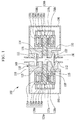
- FIG. 1 is a cross-sectional view of a linear expander according to an exemplary embodiment of the present invention.
- a linear expander 100 includes a body portion 110 having a through-out expansion space provided for a fluid to pass, first and second linear generating portions 130a and 130b respectively connected to lateral sides of the body portion 110 and thus connected with the an expansion space 115, and suction and discharge valves 170 and 180 respectively provided in front and rear sides of the expansion space 115 along a liquid passage direction.
- the body portion 110 includes a suction hole 111 through which an external high-pressure fluid flows into the linear expander 100 and a discharge hole 112 flowing a low-pressure fluid of which a pressure is decreased due to expansion to the outside of the linear expander 110, and the expansion space 115 is disposed between the suction hole 111 and the discharge hole 112.
- a first hole 113 and a second hole 114 are provided at lateral sides of the body portion 110, and they are opened and communicated with the expansion space 115.
- Two pistons 137a and 137b may linearly reciprocate along the first and second holes 113 and 114.
- cylinders 138a and 138b are respectively inserted into the first and second holes 113 and 114 provided in the body portion 110, and the pistons 137a and 137b are respectively inserted into the cylinders 138a and 138b such that the pistons can linearly reciprocate.
- first hole 113 and the second hole 114 of the body portion 110 are connected with the expansion space 115 between the suction hole 111 and the discharge hole 112 in order to let the pistons 137a and 137b move by an expansion force of the fluid in the expansion space 115, and the first hole 113 and the second hole 114 may be symmetrical to each other on the same straight line with respect to the expansion space 115.
- the shape of the body portion 110 may be horizontally symmetrical to each other with respect to the expansion space 115 as shown in FIG. 1 , but this is not restrictive.
- the suction hole 111 and the discharge hole 112 are respectively disposed in a direction that is perpendicular to the straight line direction along which the pistons 137a and 137b reciprocate to thereby allow the fluid to pass.
- the body portion 110 may further include a discharge hole connection member 150 provided for forming a discharge valve 180 and an inflow connection member 160 that guides an external high-pressure fluid to the suction hole 111, and in the present exemplary embodiment, the discharge hole connection member 150 and the inflow connection member 160 are combined to a body member 118 such that the body portion 110 is formed.
- the first linear generating portion 130a and the second linear generating portion 130b are respectively provided in lateral sides of the body portion 110 in a symmetrical manner.
- the pistons 137a and 137b of the first and second linear generating portions 130a and 130b linearly reciprocate to the opposite directions respectively in the first hole 113 and the second hole 114 to generate an induced electromotive force by a force generated from expansion of the fluid in the expansion space 115 of the body portion 110.
- the first linear generating portion 130a and the second linear generating portion 130b may respectively include the pistons 137a and 137b, the cylinders 138a and 138b, and linear generators 139a and 139b.
- the cylinders 138a and 138b formed in a shape that partially includes a cylindrical portion are inserted into the first hole 113 and the second hole 114 of the body portion 110, and the pistons 137a and 137b are inserted into the cylindrical portion and thus are guided to perform a reciprocation motion.
- the linear generators 139a and 139b may be formed of inner stators 133a and 133b, outer stators 131 a and 131b where coils 132a and 132b are wound while having a gap from the inner stators 133a and 133b, and operators 134a and 134b formed of permanent magnets.
- the operators 134a and 134b connected with the pistons 137a and 137b by the piston connection members 135a and 135b may also linearly move along with the movement of the pistons 137a and 137b.
- an induced electromotive force may be generated in the coils 132a and 132b provided in the outer stators 131 a and 131 b.
- elastic members 136a and 136b may be connected to rear ends of the piston connection members 135a and 135b that connect the above-stated operators 134a and 134b and the pistons 137a and 137b.
- the elastic members 136a and 136b may be formed as flat-shaped springs or coil springs.
- the operator 134a and 134b may provide spring stiffness with magnetic springs thereof rather than using the metallic elastic members 136a and 136b.
- the suction valve 170 closes and opens the suction hole 111 to allow the external high-pressure fluid to flow into the expansion space 115 of the body portion 110 through the suction hole 111.
- the discharge valve 180 closes and opens the discharge hole 112 to allow the fluid of which pressure is reduced in the expansion space 115 of the body portion 110 to flow to the outside through the discharge hole 112.
- an external pressure of the suction hole 111 is always higher than an internal pressure of the expansion space 115, and an external pressure of the discharge hole 112 is always set to be lower than the pressure of the expansion space 115.
- the suction valve 170 and the discharge valve 180 may be set to be in a normally open state.
- the suction valve 170 In the normally open state, the suction valve 170 is being opened even through if the external pressure is high and then is closed at the moment that the pressure of the fluid in the expansion space 115 is decreased, and thus an internal and external pressure difference becomes greater than a predetermined value instance to thereby prevent an external high-pressure fluid of the suction hole 111 from flowing into the expansion space 115.
- the discharge valve 180 in the normally open state, the discharge valve 180 is being in the closed state because an external pressure difference between the expansion space 115 and the discharge hole 112 is high, and then is opened when the pressure difference between the outside of the discharge hole 112 and the expansion space 115 is decreased to be lower than a predetermined value as the pressure of the expansion space 115 is decreased due to expansion to thereby allow the fluid in the expansion space 115 to flow to the outside through the discharge hole 112.
- the predetermined value of the pressure difference between the outside of the suction hole 111 and the expansion space 115 may be equal to or different from the predetermined value of the pressure difference between the outside of the discharge hole 112 and the expansion space 115.
- the predetermined values of the pressure difference may be set by designing shapes and sizes of the suction valve 170 and the discharge valve 180 for assembling and processing.
- the term, "normally open” implies a structure in which a valve is opened when no external force is applied and closed when a pressure force from a pressure difference becomes greater than a predetermined value.
- the suction valve 170 and the discharge valve 180 are passive valves, and a desired condition can be acquired by designing sizes of the valve for processing and assembling.
- the suction valve 170 and the discharge valve 180 may be formed as electric valves that receive a signal according to an internal pressure of the expansion space 115 or a location of the pistons 137a and 137b and thus being opened or closed by an electrical signal, and may be formed as mechanical valves that can be automatically opened or closed according to a pressure difference between the inside and the outside of the expansion space 115.
- suction valve 170 and the discharge valve 180 formed as mechanical valves will be described with reference to FIG. 2 and FIG. 3 .
- FIG. 2 is a perspective view of a normally open structure of a reed valve that can be applied as the suction valve or the discharge valve of the linear expander according to the exemplary embodiment of the present invention
- FIG. 3 is a perspective view of the reed valve of FIG. 2 in a closed state.
- a reed valve 200 which is a mechanical valve, may be used, and FIG. 2 exemplarily illustrates the reed valve 200.
- the reed valve 200 may be formed by including a stopper portion 210 and reed portions 220.
- the stopper portion 210 formed in a shape of a plate, is separated by a predetermined distance from an opening 250 to allow the flow to flow into or flow out through the opening 250, and when a pressure difference is increased, the stopper portion 210 covers the opening 250 where the fluid flows to thereby prevent the fluid from flowing.
- a portion of the stopper portion 210, contacting the opening 250 may be made of a polymer material for sealing, and for example, a material such as Rulon, Kapton, and the like may be used.
- the reed portions 220 are elastic members that fix the stopper portion 210 to the body portion 110, and move the stopper portion 210 by an elastic force according to a pressure difference between a front side and a rear side of the stopper portion 210 to close/open the opening portion 250 where the fluid flows.
- a pressure of the front side of the stopper portion 210 is significantly greater than a pressure of the rear side, which is the bottom of the stopper portion 210, a pressure difference is low and thus the reed valve 200 is opened.
- FIG. 3 the pressure difference between the front side and the rear side is increased and thus the reed valve 200 is closed.
- a valve having a normally open structure is applied as the suction valve 170 and the discharge valve 180, and thus the valve is being opened even through an external pressure is greater than an internal pressure and is opened when an external and internal pressure difference becomes greater than a predetermined value.
- the linear expander 100 may further include the above-stated discharge hole connection member 150 for forming the discharge valve 180.
- the discharge hole connection member 150 has a through-hole through which the fluid flows through the discharge hole 112, and may have a stepped shape to form a separated space between the discharge hole 112 and the expansion space 115 by being combined with the body member 118.
- a protrusion 152 may be formed at the end of the discharge hole 112 that faces the expansion space 115, and the protrusion 152 protrudes toward the discharge valve 180 to limit a movement range of the discharge valve 180.
- the discharge valve 180 that can be automatically opened and closed can be easily installed in the body portion 110 by installing the discharge valve 180 in the discharge hole connection member 150 and then combining the discharge hole connection member 150 back to the body member 118.
- the suction valve 170 may be formed in the suction hole 111 provided in the body portion 110 as shown in FIG. 1 , and in this case, the linear expander 100 may further include the suction hole connection member 160 that guides the fluid to the suction hole 111 from the outside.
- a housing 190 is fixed to an outer side of the body portion 110, and the housing may close and seal the inside while surrounding the first linear generating portion 130a and the second linear generating portion 130b.
- the structure of the linear expander 100 can be simplified and especially the pistons 137a and 137b may have a simple structure.
- FIG. 4A is a pressure-volume diagram (i.e., a p-v diagram) indicating operation of the linear expander according to the exemplary embodiment of the present invention
- FIG. 4B is a graph illustrating a valve open/close timing and piston locations according to operation of the linear expander according to the exemplary embodiment of the present invention.
- the linear expander 100 may operate an isobaric suction process between points 1 and 2 in the p-v diagram, an adiabatic expansion process between points 2 and 3, an isobaric discharge process between points 3 and 4, and an adiabatic compression process between points 4 and 1 within one cycle, and as the cycle is being repeated, the high-pressure fluid flowing in through the suction hole 111 expands with low pressure such that the low-pressure fluid can be continuously flows out through the discharge hole 112.
- the suction valve 170 (refer to the solid line in FIG. 4B ) maintains an opened state during the isobaric suction process and the discharge valve 180 (refer to the broken line in FIG. 4B ) maintains a closed state between points 1 and 2, and the pistons 137a and 137b move to the outside while being gradually distanced from each other.
- the suction valve 170 and the discharge valve 180 maintain the closed state, and the pistons 137a and 137b move to the outside while being continuously distanced from each other.
- the suction valve 170 maintains the closed state and the discharge valve 180 maintains the opened state, and the pistons 137a and 137b move to the inside while being closer to each other.
- the suction valve 170 and the discharge valve 180 maintain the closed state and the pistons 137a and 137b move to the inward while being continuously closer to each other.
- FIG. 5A is a cross-sectional view illustrating the linear expander according to the exemplary embodiment of the present invention in the isobaric suction process from point 1 to point 2 in the p-v diagram of FIG. 4A
- FIG. 5B is a cross-sectional view illustrating the linear expander in the adiabatic expansion process from point 2 to point 3 in the p-v line of FIG. 4A
- FIG. 5C is a cross-sectional view illustrating the linear expander in the isobaric discharge process from point 3 to point 4 in the p-v line of FIG. 4A
- FIG. 5D is a cross-sectional view illustrating the linear expander in the adiabatic compression process from point 4 to point 1 in the p-v line of FIG. 4A .
- FIG. 5A illustrates the isobaric suction process (1 ⁇ 2), and a system high-pressure P H formed in the outside of the suction hole 111 is maintained to be always be higher than a pressure P C of the expansion space 115.
- a pressure difference between the system high-pressure P H and the pressure P C of the expansion space 115 is reduced and thus the suction valve 170 maintains the opened state such that the high-pressure fluid flows into the body portion 110.
- the pistons 137a and 137b move to the outside in the bilateral directions respectively such that the pressure P C of the expansion space 115 can be maintained at a constant level.
- the pressure P C of the expansion space 115 is always higher than a system low pressure P L formed in the outside of the discharge hole 112, and a difference between the pressure P C and the system low pressure P L is too high such that the discharge valve 180 is being closed, and the high-pressure fluid flows into the body portion 110 from the system high pressure P H while stopping outflow of the fluid.
- the linear expander experiences the adiabatic expansion process (2 ⁇ 3), and the pressure P C of the expansion space 115 is reduced as the high-pressure gas having flowed into the expansion space 115 expands.
- a difference between the system high pressure P H and the pressure P C of the expansion space 115 is increased so that the suction valve 170 is closed.
- the pressure P C of the expansions space 115 is reduced, the difference between the system high pressure P H and the pressure P C of the expansion space 115 is still high so that the discharge valve 180 maintains the closed state.
- the pressure of the fluid reduces as the high-pressure fluid in the expansions space 115 expands, and thus the pistons 137a and 137b move to the outward in the bilateral directions respectively by the expansion force, and in such a process, the linear generators 139a and 139b can generate induced electromotive force.
- Generated electricity may be exhausted by putting a load to work, but an additional charging system may be provided and charged by the electricity or the electricity may be used as a power source of other devices (e.g., a compressor).
- an additional charging system may be provided and charged by the electricity or the electricity may be used as a power source of other devices (e.g., a compressor).
- the linear expander experiences the isobaric discharge process (3 ⁇ 4), and since the pressure P C of the expansion space 115 is gradually decreased during the adiabatic expansion process, the pressure difference with the system low P L is gradually decreased, and when the pressure difference equals the predetermined value, the discharge valve 180 is opened such that the low-pressure fluid in the expansion space 115 flows out to the outside of the linear expander 100.
- the pressure P C of the expansion space 115 maintains a constant state and the pistons 137a and 137 move to the inside again from the bilateral sides, respectively. In this case, the suction valve 170 also maintains the closed state.
- the linear expander experiences the adiabatic compression process (4 ⁇ 1), and thus compression is started again by the movement of the pistons 137a and 137b and the suction valve 170 and the discharge valve 180 both maintain the closed state.
- the processes described with reference to FIG. 5A to FIG. 5D are performed during one cycle and such a cycle is repeated such that the high-pressure fluid having flowed into the linear expander 100 from the outside is expanded to change the high-pressure fluid to low-pressure fluid and the low-pressure fluid is continuously flows out to the outside of the linear expander 100.
- the suction valve 170 and the discharge valve 180 are formed as the reed valves 200 described with reference to FIG. 2 and FIG. 3 , and various types of mechanical valves operated by a pressure difference and various electric valves operated by an electrical signal are also applicable.
- FIG. 6 is a schematic diagram illustrating a reverse Brayton cryogenic refrigeration system including a linear expander according to an exemplary embodiment of the present invention
- FIG. 7 is a T-s diagram of a reverse Brayton cryogenic refrigeration system shown in FIG. 6 .
- the cryogenic refrigeration system 30 includes a compressor 310, a cryogenic heat exchanger 340, a linear expander 100, and a heat exchanger 350, and may cool or maintain a cooling target CT to a very low temperature by circulating refrigerant capable of transferring heat.
- the cryogenic refrigeration system 30 may be used for cooling a superconducting cable to less than -200 °C such that the superconducting cable can be maintained as a superconducting state.
- a compressor 310 compresses a gaseous refrigerant, and an aftercooler 320 fluidly communicates with an outlet of the compressor 310 such that the aftercooler 320 may remove compression heat generated during compressing the refrigerant.
- the cryogenic heat exchanger 340 fluidly communicates with an outlet of the aftercooler 320, and the cryogenic heat exchanger 340 may transfer the heat of the refrigerant passed through the aftercooler 320 to the refrigerant flowing into the compressor 310.
- a linear expander 100 fluidly communicates with an outlet of the cryogenic heat exchanger 340 such that the linear expander 100 may receive and expand the refrigerant passed through the cryogenic heat exchanger 340.
- the linear expander explained in reference to FIG. 1 through FIG. 5D may be used for the linear expander 100 of the cryogenic refrigeration system 30.
- a counter flow type cryogenic heat exchanger may be used for the cryogenic heat exchanger 340 of the cryogenic refrigeration system 30. In the counter flow type cryogenic heat exchanger, high temperature high pressure gas and low temperature low pressure gas exchange heat while flowing in directions opposite to each other.
- the heat exchanger 350 fluidly communicates with an outlet of the linear expander 100 and an inlet of the cryogenic heat exchanger 340.
- the heat exchanger 350 contacts with the cooling target CT, and may transfer heat from the cooling target CT to the refrigerant.
- the cooling target CT may be a solid matter or a fluid including liquid and gas.
- the compressor 310 compresses low pressure gaseous refrigerant (1 ⁇ 2), and the aftercooler 320 removes compression heat generated during compressing the refrigerant (2 ⁇ 3), and then the cryogenic heat exchanger 340 cools the refrigerant with low pressure low temperature gas (3 ⁇ 4).
- the high pressure gaseous refrigerant expands to a low pressure and works outward to drop the temperature (4 ⁇ 5), and then the temperature of the gaseous refrigerant goes up to some extent while cooling the cooling target CT contacting the heat exchanger 350 (5 ⁇ 6).
- the cryogenic heat exchanger 340 cools high pressure high temperature gaseous refrigerant (6 ⁇ 1), and then the refrigerant flows again into the compressor 310.
- the process of 3 ⁇ 4 ⁇ 5 ⁇ 6 ⁇ 1 is operated at a temperature lower than room temperature and thus may be vacuum insulated to prevent heat invasion from outside.
- linear expander 110 body portion 111: suction hole 112: discharge hole 113: first hole 114: second hole 115: expansion space 130a: first linear generating portion 130b: second linear generating portion 131 a, 131b: external stator 132a, 132b: coil 133a, 133b: internal stator 135a, 135b: piston connection member 136a, 136b: elastic member 137a, 137b: piston 138a, 138b: cylinder 139a, 139b: linear generator 150: discharge hole connection member 152: protrusion 160: suction hole connection member 170: suction valve 180: discharge valve 190: housing 200: reed valve 210: stopper portion 220: reed portion 30: cryogenic refrigeration system 310: compressor 320: aftercooler 340: cryogenic heat exchanger 350: heat exchanger CT: cooling target
Landscapes
- Engineering & Computer Science (AREA)
- Mechanical Engineering (AREA)
- General Engineering & Computer Science (AREA)
- Physics & Mathematics (AREA)
- Thermal Sciences (AREA)
- Compressors, Vaccum Pumps And Other Relevant Systems (AREA)
- Compressor (AREA)
- Check Valves (AREA)
Abstract
Description
- The present invention relates to a linear expander, and more particularly, it relates to a linear expander having a simple structure and that can operate with a high frequency and can be used at a cryogenic temperature, and a cryogenic refrigeration system including the linear expander.
- A reverse Brayton system operates with processes of compression, cooling, expansion and heating, and generates refrigeration work by adiabatic expansion of working gas. An adiabatic expansion can acquire a more significant cooling effect compared to Joule-Thomson expansion, because a high pressure gas works to the outside during expansion process. However, a sophisticated mechanical device of expander is required for adiabatic expansion.
- Currently, a cryogenic temperature expander operated at a cryogenic temperature is broadly classified into a reciprocating expander and a turbo expander.
- A conventional reciprocating expander discharges the generated expansion work to the outside through a process of changing a linear motion to a rotational motion using a crank, a cam, and the like. However, the reciprocating expander is large in size and operation frequency is as low as several Hertz. Further, the reciprocating expander has a structure in which a crank is connected between the inside and the outside of the expander such that noise and vibration are generated, and is inefficient because leakage and thermal losses occur due to internal and external temperature and pressure differences.
- A turbo expander using an impeller that rotates with at an extremely high speed has an excellent efficiency, but it has been facing a technical barrier because the expander requires a bearing technology sufficiency to support the impeller that rotates with at a speed as high as several kilohertz.
- Thus, the present invention suggests a new expander that can solve the low efficiency and generation of noise and vibration problems of the reciprocating expander in and can solve the problem of the turbo expander, which is the high technical barrier.
- The above information disclosed in this Background section is only for enhancement of understanding of the background of the invention and therefore it may contain information that does not form the prior art that is already known in this country to a person of ordinary skill in the art.
- In one aspect, the present invention has been made in an effort to provide a linear expander that can structurally offset vibration and noise caused from piston movement by moving pistons combined to two linear generators symmetrically provided in a body portion where a suction valve and a discharge valve are respectively provided to bilaterally opposite directions.
- Further, the present invention provides a linear expander, particularly, a linear expander having a simple-structured piston by having a structure in which a fluid flows in and out through a body portion regardless of a movement direction of a piston.
- In addition, the present invention provides a linear expander that can reduce energy loss caused by internal and external temperature and pressure differences of the expander by changing energy generated from expansion to electrical energy using linear generators provided in a completely closed and sealed housing.
- In another aspect, the present invention provides a cryogenic refrigeration system including the linear expander.
- In the following detailed description, only certain exemplary embodiments of the present invention have been shown and described, simply by way of illustration. As those skilled in the art would realize, the described embodiments may be modified in various different ways, all without departing from the spirit or scope of the present invention.
- A linear expander according to an exemplary embodiment of the present invention includes: a body portion including a suction hole through which a fluid having a first pressure flows in, a discharge hole through which the fluid flows out with a second pressure that is lower than the first pressure, and first and second holes connecting an expansion space formed between the suction hole and the discharge hole; a first linear generating portion and a second linear generating portion respectively causing pistons provided in the first hole and the second hole to linearly reciprocate to generate an induced electromotive force with an expansion force generated when the fluid having the first pressure expands to the fluid having the second pressure; a suction valve opening and closing the suction hole; and a discharge valve and closing the discharge hole.
- The first hole and the second hole may be symmetrical to each other on the same straight line with respect to the expansion space, and the first linear generating portion and the second linear generating portion may be provided symmetrically to each other in the lateral sides of the body portion.
- The suction valve and the discharge valve may be set to be in a normally open state.
- The suction valve may be closed to prevent inflow of the fluid having the first pressure when a pressure in the expansion space is reduced and thus a pressure difference between the outside of the suction hole and the expansion space is greater than a predetermined value, and the discharge valve may be opened to let the fluid in the expansion space to flow out when the pressure in the expansion space is reduced and thus a pressure difference between the outside of the discharge hole and the expansion space is lower than a predetermined value.
- Further, the suction valve and the discharge valve may be respectively formed as reed valves.
- The body portion may include a body member having the expansion space. And the linear expander may further include an discharge hole connection member combined with the body member to form a space between the expansion space and the discharge hole of the body portion and having a through-hole through which a fluid having flowed out from the discharge hole flows out, wherein the discharge valve is provided at the end of the through-hole. The discharge valve may include a stopper portion stopping the end of the through-hole that faces the expansion space; and reed portions connected to the stopper portion and providing an elastic force to close and open the stopper portion by a pressure difference between a front side and a rear side of the stopper portion.
- The suction valve may include: a stopper portion stopping the suction hole; and reed portions connected to the stopper portion and providing an elastic force to close and open the stopper portion by a pressure difference between a front side and a rear side of the stopper portion.
- Each of the first linear generating portion and the second linear generating portion may preferably include: the piston; a cylinder inserted to the first hole or the second hold formed in the body portion to provide a movement path of the piston; and a linear generator generating an induced electromotive force by movement of the piston.
- Each of the first linear generating portion and the second linear generating portion may preferably further include an elastic member provided at a rear end of a piston connection member that connects an operator of the linear generator and the piston to make the piston move according to movement of the operator.
- Further, the suction hole and the discharge hole may be preferably respectively provided in a direction perpendicular to a straight line direction along which the piston moves.
- The linear expander may further include a housing fixed to an outer side of the body portion and closing and sealing the inside while surrounding the first linear generating portion and the second linear generating portion.
- A cryogenic refrigeration system according to an exemplary embodiment of the present invention may cool a cooling target by circulating refrigerant capable of heat transfer. The cryogenic refrigeration system includes: a compressor compressing the gaseous refrigerant, an aftercooler fluidly communicating with an outlet of the compressor, the aftercooler removing compression heat generated during compressing the refrigerant, a cryogenic heat exchanger fluidly communicating with an outlet of the aftercooler, the cryogenic heat exchanger transferring the heat of the refrigerant passing through the aftercooler to the refrigerant flowing into the compressor, a linear expander fluidly communicating with an outlet of the cryogenic heat exchanger, the linear expander receiving and expanding the refrigerant passing through the cryogenic heat exchanger, and a heat exchanger fluidly communicating with an outlet of the linear expander and an inlet of the cryogenic heat exchanger, and contacting with the cooling target, the heat exchanger transferring heat from the cooling target to the refrigerant.
- According to the linear expander of the present invention, the respective pistons are moved to in bilaterally opposite directions in the two linear generators symmetrically provided in the body portion to thereby structurally offset vibration and noise caused from piston movement.
- In addition, since the fluid can flow in and out through the body portion regardless of the movement direction of the piston, the structure of the piston can be very simple.
- Further, energy generated from expansion can be changed to electrical energy by the linear generators provided in the housing so that an energy loss due to temperature and pressure differences can be reduced.
- Further, electrical energy generated by the linear generators can be used as an energy source of other devices such as a compressor and the like.
-
-
FIG. 1 is a cross-sectional view of a linear expander according to an exemplary embodiment of the present invention. -
FIG. 2 is a perspective view of normally open structure of a reed valve that can be applied as an inflow value or a discharge valve in the linear expander according to the exemplary embodiment of the present invention. -
FIG. 3 is a perspective view of the reed valueFIG. 2 in a closed state according to an increase of a pressure difference. -
FIG. 4A is shows a pressure-volume (p-v) line indicating operation of the linear expander according to the exemplary embodiment of the present invention, andFIG. 4B is a graph illustrating valve open/close timing and a piston location according to the operation of the linear expander according to the exemplary embodiment of the present invention. -
FIG. 5A is a cross-sectional view illustrating the linear expander according to the exemplary embodiment of the present invention in an isobaric suction process frompoint 1 topoint 2 in the p-v line ofFIG. 4A . -
FIG. 5B is a cross-sectional view illustrating the linear expander according to the exemplary embodiment of the present invention in an adiabatic expansion process frompoint 2 topoint 3 in the p-v line ofFIG. 4A . -
FIG. 5C is a cross-sectional view illustrating the linear expander according to the exemplary embodiment of the present invention in an isobaric discharge process frompoint 3 topoint 4 in the p-v line ofFIG. 4A . -
FIG. 5D is a cross-sectional view illustrating the linear expander according to the exemplary embodiment of the present invention in an adiabatic compression process frompoint 4 topoint 1 in the p-v line ofFIG. 4A . -
FIG. 6 is a schematic diagram illustrating a reverse Brayton cryogenic refrigeration system including a linear expander according to an exemplary embodiment of the present invention. -
FIG. 7 is a T-s diagram of a reverse Brayton cryogenic refrigeration system shown inFIG. 6 . - The present invention will be described more fully hereinafter with reference to the accompanying drawings, in which exemplary embodiments of the invention are shown. As those skilled in the art would realize, the described embodiments may be modified in various different ways, all without departing from the spirit or scope of the present invention. The drawings and description are to be regarded as illustrative in nature and not restrictive. Like reference numerals designate like elements throughout the specification. In addition, the size and thickness of each configuration shown in the drawings are arbitrarily shown for better understanding and ease of description, but the present invention is not limited thereto.
- In addition, unless explicitly described to the contrary, the word "comprise" and variations such as "comprises" or "comprising", will be understood to imply the inclusion of stated elements but not the exclusion of any other elements.
- Further, in exemplary embodiments, since like reference numerals designate like elements having the same configuration, a first exemplary embodiment is representatively described, and in other exemplary embodiments, only a configuration different from the first exemplary embodiment will be described.
- Hereinafter, a linear expander according to an exemplary embodiment of the present invention will be described with reference to the accompanying drawings.
-
FIG. 1 is a cross-sectional view of a linear expander according to an exemplary embodiment of the present invention. - A
linear expander 100 according to an exemplary embodiment of the present invention includes abody portion 110 having a through-out expansion space provided for a fluid to pass, first and second linear generatingportions body portion 110 and thus connected with the anexpansion space 115, and suction and dischargevalves expansion space 115 along a liquid passage direction. - The
body portion 110 includes asuction hole 111 through which an external high-pressure fluid flows into thelinear expander 100 and adischarge hole 112 flowing a low-pressure fluid of which a pressure is decreased due to expansion to the outside of thelinear expander 110, and theexpansion space 115 is disposed between thesuction hole 111 and thedischarge hole 112. Afirst hole 113 and asecond hole 114 are provided at lateral sides of thebody portion 110, and they are opened and communicated with theexpansion space 115. Twopistons second holes cylinders second holes body portion 110, and thepistons cylinders - In this case, the
first hole 113 and thesecond hole 114 of thebody portion 110 are connected with theexpansion space 115 between thesuction hole 111 and thedischarge hole 112 in order to let thepistons expansion space 115, and thefirst hole 113 and thesecond hole 114 may be symmetrical to each other on the same straight line with respect to theexpansion space 115. - In addition, the shape of the
body portion 110 may be horizontally symmetrical to each other with respect to theexpansion space 115 as shown inFIG. 1 , but this is not restrictive. Further, thesuction hole 111 and thedischarge hole 112 are respectively disposed in a direction that is perpendicular to the straight line direction along which thepistons - The
body portion 110 may further include a dischargehole connection member 150 provided for forming adischarge valve 180 and aninflow connection member 160 that guides an external high-pressure fluid to thesuction hole 111, and in the present exemplary embodiment, the dischargehole connection member 150 and theinflow connection member 160 are combined to abody member 118 such that thebody portion 110 is formed. - The first
linear generating portion 130a and the second linear generatingportion 130b, each having the same configuration, are respectively provided in lateral sides of thebody portion 110 in a symmetrical manner. Thepistons portions first hole 113 and thesecond hole 114 to generate an induced electromotive force by a force generated from expansion of the fluid in theexpansion space 115 of thebody portion 110. When a high-pressure gas flows into theexpansion space 115 which is partitioned into thesuction hole 111, thedischarge hole 112, and the twopistons pistons expansions space 115, and such a process is repeated. A detailed operation of thelinear expander 100 according to the exemplary embodiment of the present invention will be described later with reference toFIG. 4A to FIG. 5D . - The first
linear generating portion 130a and the second linear generatingportion 130b may respectively include thepistons cylinders linear generators - Referring to
FIG. 1 , thecylinders first hole 113 and thesecond hole 114 of thebody portion 110, and thepistons linear generators inner stators outer stators coils inner stators operators pistons expansion space 115, theoperators pistons piston connection members pistons operators coils outer stators - In order to satisfy resonance motion of the
pistons pistons elastic members piston connection members operators pistons elastic members - When the
linear expander 100 according to the exemplary embodiment of the present invention is used at a cryogenic temperature, theoperator elastic members - The
suction valve 170 closes and opens thesuction hole 111 to allow the external high-pressure fluid to flow into theexpansion space 115 of thebody portion 110 through thesuction hole 111. Thedischarge valve 180 closes and opens thedischarge hole 112 to allow the fluid of which pressure is reduced in theexpansion space 115 of thebody portion 110 to flow to the outside through thedischarge hole 112. - In the
linear expander 100 according to the exemplary embodiment of the present invention, an external pressure of thesuction hole 111 is always higher than an internal pressure of theexpansion space 115, and an external pressure of thedischarge hole 112 is always set to be lower than the pressure of theexpansion space 115. In this case, thesuction valve 170 and thedischarge valve 180 may be set to be in a normally open state. - In the normally open state, the
suction valve 170 is being opened even through if the external pressure is high and then is closed at the moment that the pressure of the fluid in theexpansion space 115 is decreased, and thus an internal and external pressure difference becomes greater than a predetermined value instance to thereby prevent an external high-pressure fluid of thesuction hole 111 from flowing into theexpansion space 115. Further, in the normally open state, thedischarge valve 180 is being in the closed state because an external pressure difference between theexpansion space 115 and thedischarge hole 112 is high, and then is opened when the pressure difference between the outside of thedischarge hole 112 and theexpansion space 115 is decreased to be lower than a predetermined value as the pressure of theexpansion space 115 is decreased due to expansion to thereby allow the fluid in theexpansion space 115 to flow to the outside through thedischarge hole 112. The predetermined value of the pressure difference between the outside of thesuction hole 111 and theexpansion space 115 may be equal to or different from the predetermined value of the pressure difference between the outside of thedischarge hole 112 and theexpansion space 115. The predetermined values of the pressure difference may be set by designing shapes and sizes of thesuction valve 170 and thedischarge valve 180 for assembling and processing. - Here, the term, "normally open" implies a structure in which a valve is opened when no external force is applied and closed when a pressure force from a pressure difference becomes greater than a predetermined value. In the present exemplary embodiment, the
suction valve 170 and thedischarge valve 180 are passive valves, and a desired condition can be acquired by designing sizes of the valve for processing and assembling. - The
suction valve 170 and thedischarge valve 180 may be formed as electric valves that receive a signal according to an internal pressure of theexpansion space 115 or a location of thepistons expansion space 115. - Hereinafter, an example of the
suction valve 170 and thedischarge valve 180 formed as mechanical valves will be described with reference toFIG. 2 andFIG. 3 . -
FIG. 2 is a perspective view of a normally open structure of a reed valve that can be applied as the suction valve or the discharge valve of the linear expander according to the exemplary embodiment of the present invention, andFIG. 3 is a perspective view of the reed valve ofFIG. 2 in a closed state. - As the
suction valve 170 or thedischarge valve 180 that is automatically opened/closed according to an internal and external pressure difference, areed valve 200, which is a mechanical valve, may be used, andFIG. 2 exemplarily illustrates thereed valve 200. Thereed valve 200 may be formed by including astopper portion 210 andreed portions 220. Thestopper portion 210, formed in a shape of a plate, is separated by a predetermined distance from anopening 250 to allow the flow to flow into or flow out through theopening 250, and when a pressure difference is increased, thestopper portion 210 covers theopening 250 where the fluid flows to thereby prevent the fluid from flowing. In this case, a portion of thestopper portion 210, contacting theopening 250, may be made of a polymer material for sealing, and for example, a material such as Rulon, Kapton, and the like may be used. Thereed portions 220 are elastic members that fix thestopper portion 210 to thebody portion 110, and move thestopper portion 210 by an elastic force according to a pressure difference between a front side and a rear side of thestopper portion 210 to close/open theopening portion 250 where the fluid flows. - In
FIG. 2 , although a pressure of the front side of thestopper portion 210 is significantly greater than a pressure of the rear side, which is the bottom of thestopper portion 210, a pressure difference is low and thus thereed valve 200 is opened. InFIG. 3 , the pressure difference between the front side and the rear side is increased and thus thereed valve 200 is closed. As described above, in thelinear expander 100 according to an exemplary embodiment of the present invention, a valve having a normally open structure is applied as thesuction valve 170 and thedischarge valve 180, and thus the valve is being opened even through an external pressure is greater than an internal pressure and is opened when an external and internal pressure difference becomes greater than a predetermined value. - Hereinabove, the example of the mechanical valve applied as the suction valve and the discharge valve of the linear expander according to the exemplary embodiment of the present invention has been described with reference to
FIG. 2 andFIG. 3 , and but any valve that can be automatically opened and closed by a pressure difference is applicable. - Referring back to
FIG. 1 , thelinear expander 100 may further include the above-stated dischargehole connection member 150 for forming thedischarge valve 180. The dischargehole connection member 150 has a through-hole through which the fluid flows through thedischarge hole 112, and may have a stepped shape to form a separated space between thedischarge hole 112 and theexpansion space 115 by being combined with thebody member 118. In this case, aprotrusion 152 may be formed at the end of thedischarge hole 112 that faces theexpansion space 115, and theprotrusion 152 protrudes toward thedischarge valve 180 to limit a movement range of thedischarge valve 180. Thedischarge valve 180 that can be automatically opened and closed can be easily installed in thebody portion 110 by installing thedischarge valve 180 in the dischargehole connection member 150 and then combining the dischargehole connection member 150 back to thebody member 118. - Likewise, the
suction valve 170 may be formed in thesuction hole 111 provided in thebody portion 110 as shown inFIG. 1 , and in this case, thelinear expander 100 may further include the suctionhole connection member 160 that guides the fluid to thesuction hole 111 from the outside. - A
housing 190 is fixed to an outer side of thebody portion 110, and the housing may close and seal the inside while surrounding the firstlinear generating portion 130a and the second linear generatingportion 130b. - In the present exemplary embodiment, when the
pistons expansion space 115, thepistons expansion space 115 with the same speed, and accordingly, vibration generated from each of the left andright pistons - In addition, since the fluid flows in or out through the
body portion 110 regardless of the movement directions of thepistons linear expander 100 can be simplified and especially thepistons - Further, when work energy is generated from the
linear generators housing 190, an energy loss due to a leakage and heat transmission caused by internal and external temperature and pressure differences of thehousing 190 can be reduced. - Hereinafter, an operation of the
linear expander 100 according to the exemplary embodiment of the present invention will be described with reference toFIG. 4A ,4B , andFIG. 5A to FIG. 5D . -
FIG. 4A is a pressure-volume diagram (i.e., a p-v diagram) indicating operation of the linear expander according to the exemplary embodiment of the present invention, andFIG. 4B is a graph illustrating a valve open/close timing and piston locations according to operation of the linear expander according to the exemplary embodiment of the present invention. Thelinear expander 100 according to the exemplary embodiment of the present invention may operate an isobaric suction process betweenpoints points points points suction hole 111 expands with low pressure such that the low-pressure fluid can be continuously flows out through thedischarge hole 112. - In addition, referring to
FIG. 4B , the suction valve 170 (refer to the solid line inFIG. 4B ) maintains an opened state during the isobaric suction process and the discharge valve 180 (refer to the broken line inFIG. 4B ) maintains a closed state betweenpoints pistons points suction valve 170 and thedischarge valve 180 maintain the closed state, and thepistons points suction valve 170 maintains the closed state and thedischarge valve 180 maintains the opened state, and thepistons points suction valve 170 and thedischarge valve 180 maintain the closed state and thepistons -
FIG. 5A is a cross-sectional view illustrating the linear expander according to the exemplary embodiment of the present invention in the isobaric suction process frompoint 1 topoint 2 in the p-v diagram ofFIG. 4A ,FIG. 5B is a cross-sectional view illustrating the linear expander in the adiabatic expansion process frompoint 2 topoint 3 in the p-v line ofFIG. 4A ,FIG. 5C is a cross-sectional view illustrating the linear expander in the isobaric discharge process frompoint 3 topoint 4 in the p-v line ofFIG. 4A , andFIG. 5D is a cross-sectional view illustrating the linear expander in the adiabatic compression process frompoint 4 topoint 1 in the p-v line ofFIG. 4A . - First,
FIG. 5A illustrates the isobaric suction process (1→2), and a system high-pressure PH formed in the outside of thesuction hole 111 is maintained to be always be higher than a pressure PC of theexpansion space 115. In this case, a pressure difference between the system high-pressure PH and the pressure PC of theexpansion space 115 is reduced and thus thesuction valve 170 maintains the opened state such that the high-pressure fluid flows into thebody portion 110. As the high-pressure fluid flows in, thepistons expansion space 115 can be maintained at a constant level. In this case, the pressure PC of theexpansion space 115 is always higher than a system low pressure PL formed in the outside of thedischarge hole 112, and a difference between the pressure PC and the system low pressure PL is too high such that thedischarge valve 180 is being closed, and the high-pressure fluid flows into thebody portion 110 from the system high pressure PH while stopping outflow of the fluid. - Next, as shown in
FIG. 5B , the linear expander experiences the adiabatic expansion process (2→3), and the pressure PC of theexpansion space 115 is reduced as the high-pressure gas having flowed into theexpansion space 115 expands. Thus, a difference between the system high pressure PH and the pressure PC of theexpansion space 115 is increased so that thesuction valve 170 is closed. Although the pressure PC of theexpansions space 115 is reduced, the difference between the system high pressure PH and the pressure PC of theexpansion space 115 is still high so that thedischarge valve 180 maintains the closed state. The pressure of the fluid reduces as the high-pressure fluid in theexpansions space 115 expands, and thus thepistons linear generators - Generated electricity may be exhausted by putting a load to work, but an additional charging system may be provided and charged by the electricity or the electricity may be used as a power source of other devices (e.g., a compressor).
- Next, as shown in
FIG. 5C , the linear expander experiences the isobaric discharge process (3→4), and since the pressure PC of theexpansion space 115 is gradually decreased during the adiabatic expansion process, the pressure difference with the system low PL is gradually decreased, and when the pressure difference equals the predetermined value, thedischarge valve 180 is opened such that the low-pressure fluid in theexpansion space 115 flows out to the outside of thelinear expander 100. When the fluid in theexpansion space 115 flows out, the pressure PC of theexpansion space 115 maintains a constant state and thepistons 137a and 137 move to the inside again from the bilateral sides, respectively. In this case, thesuction valve 170 also maintains the closed state. - Next, as shown in
FIG. 5D , the linear expander experiences the adiabatic compression process (4→1), and thus compression is started again by the movement of thepistons suction valve 170 and thedischarge valve 180 both maintain the closed state. - As described, the processes described with reference to
FIG. 5A to FIG. 5D are performed during one cycle and such a cycle is repeated such that the high-pressure fluid having flowed into thelinear expander 100 from the outside is expanded to change the high-pressure fluid to low-pressure fluid and the low-pressure fluid is continuously flows out to the outside of thelinear expander 100. - In
FIG. 5A to FIG. 5D , thesuction valve 170 and thedischarge valve 180 are formed as thereed valves 200 described with reference toFIG. 2 andFIG. 3 , and various types of mechanical valves operated by a pressure difference and various electric valves operated by an electrical signal are also applicable. -
FIG. 6 is a schematic diagram illustrating a reverse Brayton cryogenic refrigeration system including a linear expander according to an exemplary embodiment of the present invention, andFIG. 7 is a T-s diagram of a reverse Brayton cryogenic refrigeration system shown inFIG. 6 . - Referring to
FIG. 6 , thecryogenic refrigeration system 30 includes acompressor 310, acryogenic heat exchanger 340, alinear expander 100, and aheat exchanger 350, and may cool or maintain a cooling target CT to a very low temperature by circulating refrigerant capable of transferring heat. For example, thecryogenic refrigeration system 30 may be used for cooling a superconducting cable to less than -200 °C such that the superconducting cable can be maintained as a superconducting state. - A
compressor 310 compresses a gaseous refrigerant, and anaftercooler 320 fluidly communicates with an outlet of thecompressor 310 such that theaftercooler 320 may remove compression heat generated during compressing the refrigerant. Thecryogenic heat exchanger 340 fluidly communicates with an outlet of theaftercooler 320, and thecryogenic heat exchanger 340 may transfer the heat of the refrigerant passed through theaftercooler 320 to the refrigerant flowing into thecompressor 310. - A
linear expander 100 fluidly communicates with an outlet of thecryogenic heat exchanger 340 such that thelinear expander 100 may receive and expand the refrigerant passed through thecryogenic heat exchanger 340. The linear expander explained in reference toFIG. 1 through FIG. 5D may be used for thelinear expander 100 of thecryogenic refrigeration system 30. A counter flow type cryogenic heat exchanger may be used for thecryogenic heat exchanger 340 of thecryogenic refrigeration system 30. In the counter flow type cryogenic heat exchanger, high temperature high pressure gas and low temperature low pressure gas exchange heat while flowing in directions opposite to each other. - The
heat exchanger 350 fluidly communicates with an outlet of thelinear expander 100 and an inlet of thecryogenic heat exchanger 340. Theheat exchanger 350 contacts with the cooling target CT, and may transfer heat from the cooling target CT to the refrigerant. The cooling target CT may be a solid matter or a fluid including liquid and gas. - Referring to
FIGS. 6 and7 , an operating process of the cryogenic refrigeration system according to the embodiment will be explained below. - The
compressor 310 compresses low pressure gaseous refrigerant (1→2), and theaftercooler 320 removes compression heat generated during compressing the refrigerant (2→3), and then thecryogenic heat exchanger 340 cools the refrigerant with low pressure low temperature gas (3→4). The high pressure gaseous refrigerant expands to a low pressure and works outward to drop the temperature (4→5), and then the temperature of the gaseous refrigerant goes up to some extent while cooling the cooling target CT contacting the heat exchanger 350 (5→6). Thecryogenic heat exchanger 340 cools high pressure high temperature gaseous refrigerant (6→1), and then the refrigerant flows again into thecompressor 310. - In
FIG. 6 , the process of 3→4→5→6→1 is operated at a temperature lower than room temperature and thus may be vacuum insulated to prevent heat invasion from outside. - While this invention has been described in connection with what is presently considered to be practical exemplary embodiments, it is to be understood that the invention is not limited to the disclosed embodiments, but, on the contrary, is intended to cover various modifications and equivalent arrangements included within the spirit and scope of the appended claims.
<Description of symbols> 100: linear expander 110: body portion 111: suction hole 112: discharge hole 113: first hole 114: second hole 115: expansion space 130a: first linear generating portion 130b: second linear generating portion 131 a, 131b: external stator 132a, 132b: coil 133a, 133b: internal stator 135a, 135b: piston connection member 136a, 136b: elastic member 137a, 137b: piston 138a, 138b: cylinder 139a, 139b: linear generator 150: discharge hole connection member 152: protrusion 160: suction hole connection member 170: suction valve 180: discharge valve 190: housing 200: reed valve 210: stopper portion 220: reed portion 30: cryogenic refrigeration system 310: compressor 320: aftercooler 340: cryogenic heat exchanger 350: heat exchanger CT: cooling target
Claims (13)
- A linear expander comprising:a body portion comprising a suction hole through which a fluid having a first pressure flows in, a discharge hole through which the fluid flows out with a second pressure that is lower than the first pressure, and first and second holes connecting an expansion space formed between the suction hole and the discharge hole;a first linear generating portion and a second linear generating portion respectively causing pistons provided in the first hole and the second hole to linearly reciprocate to generate an induced electromotive force with an expansion force generated when the fluid having the first pressure expands to the fluid having the second pressure;a suction valve opening and closing the suction hole; anda discharge valve opening and closing the discharge hole.
- The linear expander of claim 1, wherein the first hole and the second hole are symmetrical to each other on the same straight line with respect to the expansion space, and the first linear generating portion and the second linear generating portion are provided symmetrically to each other in the lateral sides of the body portion.
- The linear expander of claim 1, wherein the suction valve and the discharge valve are set to be in a normally open state.
- The linear expander of claim 3, wherein the suction valve is closed to prevent inflow of the fluid having the first pressure when a pressure in the expansion space is reduced and thus a pressure difference between the outside of the suction hole and the expansion space is greater than a predetermined value, and
the discharge valve is opened to let the fluid in the expansion space to flow out when the pressure in the expansion space is reduced and thus a pressure difference between the outside of the discharge hole and the expansion space is lower than a predetermined value. - The linear expander of claim 1, wherein the suction valve and the discharge valve are respectively formed as reed valves.
- The linear expander of claim 5, wherein the body portion includes a body member having the expansion space, and
further comprising a discharge hole connection member combined with the body member to form a space between the expansion space and the discharge hole of the body portion and having a through-hole through which a fluid having flowed out from the discharge hole flows out, wherein the discharge valve is provided at the end of the through-hole. - The linear expander of claim 5, wherein the discharge valve comprises:a stopper portion stopping the end of the through-hole that faces the expansion space; andreed portions connected to the stopper portion and providing an elastic force to close and open the stopper portion by a pressure difference between a front side and a rear side of the stopper portion.
- The linear expander of claim 5, wherein the suction valve comprises:a stopper portion stopping the suction hole; andreed portions connected to the stopper portion and providing an elastic force to close and open the stopper portion by a pressure difference between a front side and a rear side of the stopper portion.
- The linear expander of claim 1, wherein each of the first linear generating portion and the second linear generating portion comprises:the piston;a cylinder inserted to the first hole or the second hold formed in the body portion to provide a movement path of the piston; anda linear generator generating an induced electromotive force by movement of the piston.
- The linear expander of claim 9, wherein each of the first linear generating portion and the second linear generating portion further comprises an elastic member provided at a rear end of a piston connection member that connects an operator of the linear generator and the piston to make the piston move according to movement of the operator.
- The linear expander of claim 1, wherein the suction hole and the discharge hole are respectively provided in a direction perpendicular to a straight line direction along which the piston moves.
- The linear expander of claim 1, further comprising a housing fixed to an outer side of the body portion and closing and sealing the inside while surrounding the first linear generating portion and the second linear generating portion.
- A cryogenic refrigeration system including a linear expander according to any of claims 1 to 12, cooling a cooling target by circulating refrigerant capable of transferring heat, the system comprising:a compressor compressing the gaseous refrigerant;an aftercooler fluidly communicating with an outlet of the compressor, the aftercooler removing compression heat generated during compressing the refrigerant;a cryogenic heat exchanger fluidly communicating with an outlet of the aftercooler, the cryogenic heat exchanger transferring the heat of the refrigerant passing through the aftercooler to the refrigerant flowing into the compressor;the linear expander fluidly communicating with an outlet of the cryogenic heat exchanger, the linear expander receiving and expanding the refrigerant passing through the cryogenic heat exchanger; anda heat exchanger fluidly communicating with an outlet of the linear expander and an inlet of the cryogenic heat exchanger, and contacting with the cooling target, the heat exchanger transferring heat from the cooling target to the refrigerant.
Applications Claiming Priority (1)
| Application Number | Priority Date | Filing Date | Title |
|---|---|---|---|
| KR20150104637 | 2015-07-23 |
Publications (2)
| Publication Number | Publication Date |
|---|---|
| EP3144470A1 true EP3144470A1 (en) | 2017-03-22 |
| EP3144470B1 EP3144470B1 (en) | 2018-04-04 |
Family
ID=55236165
Family Applications (1)
| Application Number | Title | Priority Date | Filing Date |
|---|---|---|---|
| EP16150528.4A Active EP3144470B1 (en) | 2015-07-23 | 2016-01-08 | Linear expander and cryogenic refrigeration system including the same |
Country Status (5)
| Country | Link |
|---|---|
| US (1) | US10852040B2 (en) |
| EP (1) | EP3144470B1 (en) |
| JP (1) | JP6169674B2 (en) |
| KR (1) | KR102401347B1 (en) |
| CN (1) | CN106369860B (en) |
Families Citing this family (5)
| Publication number | Priority date | Publication date | Assignee | Title |
|---|---|---|---|---|
| SE545742C2 (en) * | 2020-11-02 | 2023-12-27 | Johannes Gilberg | Machine for converting thermal energy pressurized in a medium into mechanical energy |
| CN112524833A (en) * | 2020-11-30 | 2021-03-19 | 中国电子科技集团公司第十六研究所 | Low-temperature turbine refrigerator |
| EP4023860B1 (en) * | 2021-01-04 | 2023-08-23 | Volvo Car Corporation | Expander system |
| CN112747488A (en) * | 2021-02-18 | 2021-05-04 | 和昌(广州)家具有限公司 | Central air-conditioning refrigeration compression device capable of adjusting refrigerant consumption according to temperature |
| RU2757617C1 (en) * | 2021-02-25 | 2021-10-19 | Юрий Иванович Духанин | Piston detander |
Citations (6)
| Publication number | Priority date | Publication date | Assignee | Title |
|---|---|---|---|---|
| JPS61210276A (en) * | 1985-03-15 | 1986-09-18 | Fuji Electric Co Ltd | Reciprocation type compressor |
| JPH02298764A (en) * | 1989-05-12 | 1990-12-11 | Shonan Gijutsu Center Kk | Pulse tube type refrigerator |
| US5775273A (en) * | 1997-07-01 | 1998-07-07 | Sunpower, Inc. | Free piston internal combustion engine |
| US20030077192A1 (en) * | 2001-10-23 | 2003-04-24 | Dong-Koo Shin | Oil supplying apparatus for opposed type reciprocating compressor |
| JP2004020048A (en) * | 2002-06-17 | 2004-01-22 | Sharp Corp | Stirling Institution |
| US20110219810A1 (en) * | 2010-03-15 | 2011-09-15 | Sumitomo (Shi) Cryogenics Of America, Inc. | Gas balanced cryogenic expansion engine |
Family Cites Families (18)
| Publication number | Priority date | Publication date | Assignee | Title |
|---|---|---|---|---|
| US4457670A (en) * | 1978-09-28 | 1984-07-03 | General Electric Company | Methods and apparatus for pumping compressible dynamoelectric machine lubricant material |
| JPH02263060A (en) | 1989-03-31 | 1990-10-25 | Aisin Seiki Co Ltd | Turboexpansion device for supercryogenic refrigerating machine |
| JPH0774538B2 (en) | 1992-06-26 | 1995-08-09 | ヤシマ工業株式会社 | Double wall structure of building |
| US5850111A (en) | 1994-05-05 | 1998-12-15 | Lockheed Martin Energy Research Corp. | Free piston variable-stroke linear-alternator generator |
| DE10219549B4 (en) | 2002-04-25 | 2004-03-11 | Deutsches Zentrum für Luft- und Raumfahrt e.V. | Free-piston combustion device with electric linear drive |
| US7082909B2 (en) | 2002-04-25 | 2006-08-01 | Deutsches Zentrum Fur Luft- Und Raumfahrt E.V. | Free-piston device with electric linear drive |
| JP2005155345A (en) | 2003-11-20 | 2005-06-16 | Denso Corp | Free piston engine and power generator using the same |
| US7032400B2 (en) | 2004-03-29 | 2006-04-25 | Hussmann Corporation | Refrigeration unit having a linear compressor |
| KR100624820B1 (en) | 2004-11-05 | 2006-09-18 | 엘지전자 주식회사 | Linear compressor with symmetrical compression |
| JP2006144568A (en) | 2004-11-16 | 2006-06-08 | Fuji Electric Holdings Co Ltd | Vibration type compressor |
| US20080304979A1 (en) * | 2004-12-23 | 2008-12-11 | Submachine Corp. | Reaction Drive Energy Transfer Device |
| KR100809397B1 (en) | 2005-08-26 | 2008-03-05 | 한국전자통신연구원 | Electron emission device using abruptly metal-insulator transition and display including the same |
| JP2008031857A (en) * | 2006-07-26 | 2008-02-14 | Calsonic Kansei Corp | Compressor |
| KR101045871B1 (en) * | 2008-11-27 | 2011-07-01 | 채수조 | Linear heat engine |
| GB201012743D0 (en) | 2010-07-29 | 2010-09-15 | Isentropic Ltd | Valves |
| JP6010470B2 (en) * | 2012-04-11 | 2016-10-19 | 日本特殊陶業株式会社 | Gas sensor |
| KR101433874B1 (en) * | 2012-04-17 | 2014-08-29 | 김석민 | Refrigeration cycle used power generation apparatus |
| JP2015524039A (en) | 2012-06-26 | 2015-08-20 | コーゲン・マイクロシステムズ・ピーティーワイ・リミテッド | Expander for heat engine |
-
2015
- 2015-12-21 US US14/975,990 patent/US10852040B2/en active Active
- 2015-12-22 JP JP2015249263A patent/JP6169674B2/en active Active
-
2016
- 2016-01-08 EP EP16150528.4A patent/EP3144470B1/en active Active
- 2016-01-28 CN CN201610059133.5A patent/CN106369860B/en active Active
- 2016-04-07 KR KR1020160042646A patent/KR102401347B1/en active Active
Patent Citations (6)
| Publication number | Priority date | Publication date | Assignee | Title |
|---|---|---|---|---|
| JPS61210276A (en) * | 1985-03-15 | 1986-09-18 | Fuji Electric Co Ltd | Reciprocation type compressor |
| JPH02298764A (en) * | 1989-05-12 | 1990-12-11 | Shonan Gijutsu Center Kk | Pulse tube type refrigerator |
| US5775273A (en) * | 1997-07-01 | 1998-07-07 | Sunpower, Inc. | Free piston internal combustion engine |
| US20030077192A1 (en) * | 2001-10-23 | 2003-04-24 | Dong-Koo Shin | Oil supplying apparatus for opposed type reciprocating compressor |
| JP2004020048A (en) * | 2002-06-17 | 2004-01-22 | Sharp Corp | Stirling Institution |
| US20110219810A1 (en) * | 2010-03-15 | 2011-09-15 | Sumitomo (Shi) Cryogenics Of America, Inc. | Gas balanced cryogenic expansion engine |
Also Published As
| Publication number | Publication date |
|---|---|
| KR20170012866A (en) | 2017-02-03 |
| JP2017025898A (en) | 2017-02-02 |
| US10852040B2 (en) | 2020-12-01 |
| US20170023280A1 (en) | 2017-01-26 |
| KR102401347B1 (en) | 2022-05-26 |
| EP3144470B1 (en) | 2018-04-04 |
| JP6169674B2 (en) | 2017-07-26 |
| CN106369860A (en) | 2017-02-01 |
| CN106369860B (en) | 2018-12-25 |
Similar Documents
| Publication | Publication Date | Title |
|---|---|---|
| EP3144470B1 (en) | Linear expander and cryogenic refrigeration system including the same | |
| KR102178072B1 (en) | Linear compressor | |
| US9841011B2 (en) | Linear compressor and a linear motor for a linear compressor | |
| US20150004030A1 (en) | Linear compressor | |
| KR102612940B1 (en) | Reciprocating compressor | |
| US9677553B2 (en) | Linear compressor | |
| CN108612638B (en) | Linear compressor and refrigeration equipment | |
| US11434887B2 (en) | Linear compressor with suction guide and suction muffler | |
| KR20180093526A (en) | Linear compressor | |
| KR102184999B1 (en) | Linear compressor | |
| US20190178538A1 (en) | Linear compressor | |
| KR102280431B1 (en) | Compressor | |
| KR102439844B1 (en) | linear compressor | |
| US11555490B2 (en) | Linear compressor | |
| JP6320142B2 (en) | Cryogenic refrigerator | |
| US12031533B2 (en) | Linear compressor | |
| JPH0814684A (en) | Stirling cycle gas refrigerator | |
| CN114109782B (en) | Linear compressor | |
| WO2011105684A2 (en) | Displacer valve for a cryogenic refrigerator | |
| KR100657486B1 (en) | Linear compressor | |
| KR102356974B1 (en) | Compressor | |
| KR102399507B1 (en) | Motor and compressor including thereof | |
| KR102293484B1 (en) | Compressor | |
| KR20180035612A (en) | Compressor | |
| KR102365966B1 (en) | Compressor |
Legal Events
| Date | Code | Title | Description |
|---|---|---|---|
| PUAI | Public reference made under article 153(3) epc to a published international application that has entered the european phase |
Free format text: ORIGINAL CODE: 0009012 |
|
| STAA | Information on the status of an ep patent application or granted ep patent |
Free format text: STATUS: REQUEST FOR EXAMINATION WAS MADE |
|
| 17P | Request for examination filed |
Effective date: 20160125 |
|
| AK | Designated contracting states |
Kind code of ref document: A1 Designated state(s): AL AT BE BG CH CY CZ DE DK EE ES FI FR GB GR HR HU IE IS IT LI LT LU LV MC MK MT NL NO PL PT RO RS SE SI SK SM TR |
|
| AX | Request for extension of the european patent |
Extension state: BA ME |
|
| GRAP | Despatch of communication of intention to grant a patent |
Free format text: ORIGINAL CODE: EPIDOSNIGR1 |
|
| STAA | Information on the status of an ep patent application or granted ep patent |
Free format text: STATUS: GRANT OF PATENT IS INTENDED |
|
| RBV | Designated contracting states (corrected) |
Designated state(s): AL AT BE BG CH CY CZ DE DK EE ES FI FR GB GR HR HU IE IS IT LI LT LU LV MC MK MT NL NO PL PT RO RS SE SI SK SM TR |
|
| RIC1 | Information provided on ipc code assigned before grant |
Ipc: F01B 23/10 20060101AFI20170929BHEP Ipc: F01B 11/00 20060101ALI20170929BHEP Ipc: F01B 7/02 20060101ALI20170929BHEP |
|
| INTG | Intention to grant announced |
Effective date: 20171025 |
|
| GRAS | Grant fee paid |
Free format text: ORIGINAL CODE: EPIDOSNIGR3 |
|
| GRAA | (expected) grant |
Free format text: ORIGINAL CODE: 0009210 |
|
| STAA | Information on the status of an ep patent application or granted ep patent |
Free format text: STATUS: THE PATENT HAS BEEN GRANTED |
|
| AK | Designated contracting states |
Kind code of ref document: B1 Designated state(s): AL AT BE BG CH CY CZ DE DK EE ES FI FR GB GR HR HU IE IS IT LI LT LU LV MC MK MT NL NO PL PT RO RS SE SI SK SM TR |
|
| REG | Reference to a national code |
Ref country code: GB Ref legal event code: FG4D |
|
| REG | Reference to a national code |
Ref country code: CH Ref legal event code: EP Ref country code: CH Ref legal event code: NV Representative=s name: CABINET GERMAIN AND MAUREAU, CH |
|
| REG | Reference to a national code |
Ref country code: AT Ref legal event code: REF Ref document number: 985817 Country of ref document: AT Kind code of ref document: T Effective date: 20180415 |
|
| REG | Reference to a national code |
Ref country code: IE Ref legal event code: FG4D |
|
| REG | Reference to a national code |
Ref country code: DE Ref legal event code: R096 Ref document number: 602016002247 Country of ref document: DE |
|
| REG | Reference to a national code |
Ref country code: NL Ref legal event code: MP Effective date: 20180404 |
|
| REG | Reference to a national code |
Ref country code: LT Ref legal event code: MG4D |
|
| PG25 | Lapsed in a contracting state [announced via postgrant information from national office to epo] |
Ref country code: NL Free format text: LAPSE BECAUSE OF FAILURE TO SUBMIT A TRANSLATION OF THE DESCRIPTION OR TO PAY THE FEE WITHIN THE PRESCRIBED TIME-LIMIT Effective date: 20180404 |
|
| PG25 | Lapsed in a contracting state [announced via postgrant information from national office to epo] |
Ref country code: AL Free format text: LAPSE BECAUSE OF FAILURE TO SUBMIT A TRANSLATION OF THE DESCRIPTION OR TO PAY THE FEE WITHIN THE PRESCRIBED TIME-LIMIT Effective date: 20180404 Ref country code: ES Free format text: LAPSE BECAUSE OF FAILURE TO SUBMIT A TRANSLATION OF THE DESCRIPTION OR TO PAY THE FEE WITHIN THE PRESCRIBED TIME-LIMIT Effective date: 20180404 Ref country code: NO Free format text: LAPSE BECAUSE OF FAILURE TO SUBMIT A TRANSLATION OF THE DESCRIPTION OR TO PAY THE FEE WITHIN THE PRESCRIBED TIME-LIMIT Effective date: 20180704 Ref country code: BG Free format text: LAPSE BECAUSE OF FAILURE TO SUBMIT A TRANSLATION OF THE DESCRIPTION OR TO PAY THE FEE WITHIN THE PRESCRIBED TIME-LIMIT Effective date: 20180704 Ref country code: FI Free format text: LAPSE BECAUSE OF FAILURE TO SUBMIT A TRANSLATION OF THE DESCRIPTION OR TO PAY THE FEE WITHIN THE PRESCRIBED TIME-LIMIT Effective date: 20180404 Ref country code: LT Free format text: LAPSE BECAUSE OF FAILURE TO SUBMIT A TRANSLATION OF THE DESCRIPTION OR TO PAY THE FEE WITHIN THE PRESCRIBED TIME-LIMIT Effective date: 20180404 Ref country code: SE Free format text: LAPSE BECAUSE OF FAILURE TO SUBMIT A TRANSLATION OF THE DESCRIPTION OR TO PAY THE FEE WITHIN THE PRESCRIBED TIME-LIMIT Effective date: 20180404 Ref country code: PL Free format text: LAPSE BECAUSE OF FAILURE TO SUBMIT A TRANSLATION OF THE DESCRIPTION OR TO PAY THE FEE WITHIN THE PRESCRIBED TIME-LIMIT Effective date: 20180404 |
|
| PG25 | Lapsed in a contracting state [announced via postgrant information from national office to epo] |
Ref country code: GR Free format text: LAPSE BECAUSE OF FAILURE TO SUBMIT A TRANSLATION OF THE DESCRIPTION OR TO PAY THE FEE WITHIN THE PRESCRIBED TIME-LIMIT Effective date: 20180705 Ref country code: HR Free format text: LAPSE BECAUSE OF FAILURE TO SUBMIT A TRANSLATION OF THE DESCRIPTION OR TO PAY THE FEE WITHIN THE PRESCRIBED TIME-LIMIT Effective date: 20180404 Ref country code: LV Free format text: LAPSE BECAUSE OF FAILURE TO SUBMIT A TRANSLATION OF THE DESCRIPTION OR TO PAY THE FEE WITHIN THE PRESCRIBED TIME-LIMIT Effective date: 20180404 Ref country code: RS Free format text: LAPSE BECAUSE OF FAILURE TO SUBMIT A TRANSLATION OF THE DESCRIPTION OR TO PAY THE FEE WITHIN THE PRESCRIBED TIME-LIMIT Effective date: 20180404 |
|
| REG | Reference to a national code |
Ref country code: AT Ref legal event code: MK05 Ref document number: 985817 Country of ref document: AT Kind code of ref document: T Effective date: 20180404 |
|
| PG25 | Lapsed in a contracting state [announced via postgrant information from national office to epo] |
Ref country code: PT Free format text: LAPSE BECAUSE OF FAILURE TO SUBMIT A TRANSLATION OF THE DESCRIPTION OR TO PAY THE FEE WITHIN THE PRESCRIBED TIME-LIMIT Effective date: 20180806 |
|
| REG | Reference to a national code |
Ref country code: DE Ref legal event code: R097 Ref document number: 602016002247 Country of ref document: DE |
|
| PG25 | Lapsed in a contracting state [announced via postgrant information from national office to epo] |
Ref country code: CZ Free format text: LAPSE BECAUSE OF FAILURE TO SUBMIT A TRANSLATION OF THE DESCRIPTION OR TO PAY THE FEE WITHIN THE PRESCRIBED TIME-LIMIT Effective date: 20180404 Ref country code: RO Free format text: LAPSE BECAUSE OF FAILURE TO SUBMIT A TRANSLATION OF THE DESCRIPTION OR TO PAY THE FEE WITHIN THE PRESCRIBED TIME-LIMIT Effective date: 20180404 Ref country code: SK Free format text: LAPSE BECAUSE OF FAILURE TO SUBMIT A TRANSLATION OF THE DESCRIPTION OR TO PAY THE FEE WITHIN THE PRESCRIBED TIME-LIMIT Effective date: 20180404 Ref country code: AT Free format text: LAPSE BECAUSE OF FAILURE TO SUBMIT A TRANSLATION OF THE DESCRIPTION OR TO PAY THE FEE WITHIN THE PRESCRIBED TIME-LIMIT Effective date: 20180404 Ref country code: EE Free format text: LAPSE BECAUSE OF FAILURE TO SUBMIT A TRANSLATION OF THE DESCRIPTION OR TO PAY THE FEE WITHIN THE PRESCRIBED TIME-LIMIT Effective date: 20180404 Ref country code: DK Free format text: LAPSE BECAUSE OF FAILURE TO SUBMIT A TRANSLATION OF THE DESCRIPTION OR TO PAY THE FEE WITHIN THE PRESCRIBED TIME-LIMIT Effective date: 20180404 |
|
| PLBE | No opposition filed within time limit |
Free format text: ORIGINAL CODE: 0009261 |
|
| STAA | Information on the status of an ep patent application or granted ep patent |
Free format text: STATUS: NO OPPOSITION FILED WITHIN TIME LIMIT |
|
| PG25 | Lapsed in a contracting state [announced via postgrant information from national office to epo] |
Ref country code: IT Free format text: LAPSE BECAUSE OF FAILURE TO SUBMIT A TRANSLATION OF THE DESCRIPTION OR TO PAY THE FEE WITHIN THE PRESCRIBED TIME-LIMIT Effective date: 20180404 Ref country code: SM Free format text: LAPSE BECAUSE OF FAILURE TO SUBMIT A TRANSLATION OF THE DESCRIPTION OR TO PAY THE FEE WITHIN THE PRESCRIBED TIME-LIMIT Effective date: 20180404 |
|
| 26N | No opposition filed |
Effective date: 20190107 |
|
| PG25 | Lapsed in a contracting state [announced via postgrant information from national office to epo] |
Ref country code: SI Free format text: LAPSE BECAUSE OF FAILURE TO SUBMIT A TRANSLATION OF THE DESCRIPTION OR TO PAY THE FEE WITHIN THE PRESCRIBED TIME-LIMIT Effective date: 20180404 |
|
| REG | Reference to a national code |
Ref country code: DE Ref legal event code: R119 Ref document number: 602016002247 Country of ref document: DE |
|
| PG25 | Lapsed in a contracting state [announced via postgrant information from national office to epo] |
Ref country code: MC Free format text: LAPSE BECAUSE OF FAILURE TO SUBMIT A TRANSLATION OF THE DESCRIPTION OR TO PAY THE FEE WITHIN THE PRESCRIBED TIME-LIMIT Effective date: 20180404 |
|
| PG25 | Lapsed in a contracting state [announced via postgrant information from national office to epo] |
Ref country code: LU Free format text: LAPSE BECAUSE OF NON-PAYMENT OF DUE FEES Effective date: 20190108 |
|
| REG | Reference to a national code |
Ref country code: BE Ref legal event code: MM Effective date: 20190131 |
|
| REG | Reference to a national code |
Ref country code: IE Ref legal event code: MM4A |
|
| PG25 | Lapsed in a contracting state [announced via postgrant information from national office to epo] |
Ref country code: DE Free format text: LAPSE BECAUSE OF NON-PAYMENT OF DUE FEES Effective date: 20190801 |
|
| PG25 | Lapsed in a contracting state [announced via postgrant information from national office to epo] |
Ref country code: BE Free format text: LAPSE BECAUSE OF NON-PAYMENT OF DUE FEES Effective date: 20190131 |
|
| PG25 | Lapsed in a contracting state [announced via postgrant information from national office to epo] |
Ref country code: IE Free format text: LAPSE BECAUSE OF NON-PAYMENT OF DUE FEES Effective date: 20190108 |
|
| PG25 | Lapsed in a contracting state [announced via postgrant information from national office to epo] |
Ref country code: TR Free format text: LAPSE BECAUSE OF FAILURE TO SUBMIT A TRANSLATION OF THE DESCRIPTION OR TO PAY THE FEE WITHIN THE PRESCRIBED TIME-LIMIT Effective date: 20180404 |
|
| PG25 | Lapsed in a contracting state [announced via postgrant information from national office to epo] |
Ref country code: MT Free format text: LAPSE BECAUSE OF NON-PAYMENT OF DUE FEES Effective date: 20190108 |
|
| PG25 | Lapsed in a contracting state [announced via postgrant information from national office to epo] |
Ref country code: CY Free format text: LAPSE BECAUSE OF FAILURE TO SUBMIT A TRANSLATION OF THE DESCRIPTION OR TO PAY THE FEE WITHIN THE PRESCRIBED TIME-LIMIT Effective date: 20180404 |
|
| PG25 | Lapsed in a contracting state [announced via postgrant information from national office to epo] |
Ref country code: IS Free format text: LAPSE BECAUSE OF FAILURE TO SUBMIT A TRANSLATION OF THE DESCRIPTION OR TO PAY THE FEE WITHIN THE PRESCRIBED TIME-LIMIT Effective date: 20180804 |
|
| PG25 | Lapsed in a contracting state [announced via postgrant information from national office to epo] |
Ref country code: HU Free format text: LAPSE BECAUSE OF FAILURE TO SUBMIT A TRANSLATION OF THE DESCRIPTION OR TO PAY THE FEE WITHIN THE PRESCRIBED TIME-LIMIT; INVALID AB INITIO Effective date: 20160108 |
|
| PG25 | Lapsed in a contracting state [announced via postgrant information from national office to epo] |
Ref country code: MK Free format text: LAPSE BECAUSE OF FAILURE TO SUBMIT A TRANSLATION OF THE DESCRIPTION OR TO PAY THE FEE WITHIN THE PRESCRIBED TIME-LIMIT Effective date: 20180404 |
|
| PGFP | Annual fee paid to national office [announced via postgrant information from national office to epo] |
Ref country code: FR Payment date: 20251231 Year of fee payment: 11 |
|
| REG | Reference to a national code |
Ref country code: CH Ref legal event code: U11 Free format text: ST27 STATUS EVENT CODE: U-0-0-U10-U11 (AS PROVIDED BY THE NATIONAL OFFICE) Effective date: 20260201 |
|
| PGFP | Annual fee paid to national office [announced via postgrant information from national office to epo] |
Ref country code: GB Payment date: 20260106 Year of fee payment: 11 |
|
| PGFP | Annual fee paid to national office [announced via postgrant information from national office to epo] |
Ref country code: CH Payment date: 20260201 Year of fee payment: 11 |