EP3143858A1 - Gezogene verteilmaschine - Google Patents
Gezogene verteilmaschine Download PDFInfo
- Publication number
- EP3143858A1 EP3143858A1 EP16401055.5A EP16401055A EP3143858A1 EP 3143858 A1 EP3143858 A1 EP 3143858A1 EP 16401055 A EP16401055 A EP 16401055A EP 3143858 A1 EP3143858 A1 EP 3143858A1
- Authority
- EP
- European Patent Office
- Prior art keywords
- reservoir
- conveyor belt
- drawbar
- relief element
- length
- Prior art date
- Legal status (The legal status is an assumption and is not a legal conclusion. Google has not performed a legal analysis and makes no representation as to the accuracy of the status listed.)
- Granted
Links
Images


Classifications
-
- A—HUMAN NECESSITIES
- A01—AGRICULTURE; FORESTRY; ANIMAL HUSBANDRY; HUNTING; TRAPPING; FISHING
- A01C—PLANTING; SOWING; FERTILISING
- A01C15/00—Fertiliser distributors
- A01C15/12—Fertiliser distributors with movable parts of the receptacle
- A01C15/122—Fertiliser distributors with movable parts of the receptacle with moving floor parts
-
- A—HUMAN NECESSITIES
- A01—AGRICULTURE; FORESTRY; ANIMAL HUSBANDRY; HUNTING; TRAPPING; FISHING
- A01C—PLANTING; SOWING; FERTILISING
- A01C15/00—Fertiliser distributors
- A01C15/005—Undercarriages, tanks, hoppers, stirrers specially adapted for seeders or fertiliser distributors
- A01C15/006—Hoppers
-
- E—FIXED CONSTRUCTIONS
- E01—CONSTRUCTION OF ROADS, RAILWAYS, OR BRIDGES
- E01C—CONSTRUCTION OF, OR SURFACES FOR, ROADS, SPORTS GROUNDS, OR THE LIKE; MACHINES OR AUXILIARY TOOLS FOR CONSTRUCTION OR REPAIR
- E01C19/00—Machines, tools or auxiliary devices for preparing or distributing paving materials, for working the placed materials, or for forming, consolidating, or finishing the paving
- E01C19/12—Machines, tools or auxiliary devices for preparing or distributing paving materials, for working the placed materials, or for forming, consolidating, or finishing the paving for distributing granular or liquid materials
- E01C19/20—Apparatus for distributing, e.g. spreading, granular or pulverulent materials, e.g. sand, gravel, salt, dry binders
- E01C2019/2055—Details not otherwise provided for
- E01C2019/207—Feeding the distribution means
- E01C2019/2075—Feeding the distribution means with longitudinal conveyor belt
Definitions
- the invention relates to a drawn distributor according to the preamble of claim 1.
- Such a drawn distributor is in DE 44 08 016 C2 described.
- the relief element extends over the entire length of the reservoir.
- the conveyor belt is relieved, so that the entire material reservoir located in the reservoir is not fully loaded on the conveyor belt.
- a better promotion of the material is achieved from the reservoir to the spreader.
- the relief element extends over the entire reservoir length, the material is first removed by the conveyor belt starting in the rear region of the reservoir, ie it is first of the drawbar remote area of the reservoir emptied.
- the load on the drawbar weight and thus to be taken over by the drawbar support load is increasingly larger because the relief decreases by the behind the axis of the chassis progressively lower, located there material. This creates the risk that the vertical load reaches an inadmissible value.
- the invention is based on the object to achieve in a simple manner that the redesignate material is initially removed primarily from the front, the drawbar facing portion of the reservoir through the conveyor belt.
- This object of the invention achieved in that the relief element extends from the drawbar end facing away from the reservoir in the direction of the drawbar over not more than% of the length, preferably not more than half the length of the reservoir or conveyor belt.
- the relief element extends in plan view at least approximately to the axis or center axis of the chassis.
- the researcher To ensure that preferably from the front of the reservoir, the researcher material is removed from the conveyor belt and supplied to the spreader, it is provided that in the drawbar immediately adjacent quarter, preferably third of the length of the reservoir and / or the conveyor belt no relief element is arranged.
- the relief element is at least approximately up to the axis or center axis of the chassis, but not more than 3 ⁇ 4, preferably 2 / 3 of the length of the reservoir extends.
- a plurality of passage openings for the granular material are arranged in the roof surfaces of the relief element. This makes it possible that can pass through the passages material in the rear of the reservoir down through, so that in a controlled manner at the same time in addition to the preferred removal from the front of the reservoir from the rear of the reservoir in a controlled manner material of the Transport belt is discharged in the direction of the scattering element.
- the passage openings by at least one cover at least partially coverable and / or closed.
- the cover elements may be formed as a closure plug.
- the cover is designed as a cover plate, preferably as a roof-shaped and adapted to the contour of the relief element cover plate.
- Trained as a large fertilizer spreader distributor has the support frame 1, which is supported on the chassis 2 with the wheels 3 and the axle 4 in the rear area on the ground and on the arranged at the front of the support frame 1 drawbar 5 to a device of an agricultural tractor, not shown , on.
- the reservoir 6 is arranged and fixed.
- the reservoir 6 has the two lateral reservoir walls 7, which are arranged funnel-shaped to each other.
- the reservoir 6 has a front reservoir wall 8 and a rear reservoir wall 9.
- the reservoir 6 has a bottom 10 which serves as a conveyor belt 11 for conveying material contained in the container 6 granular material to a arranged at the rear end of the conveyor belt spreader 12.
- This spreader 12 has two upright and spaced apart axes rotatably driven with Throwing vanes occupied centrifugal discs in a manner not shown.
- the conveyor belt 11 is arranged in the lower region of the storage container 6 and designed as a guided over guide rollers 13, circumferentially driven conveyor belt.
- the conveyor belt 11 extends over the entire lower width of the reservoir 6.
- a passage opening 14 is arranged, through which the conveyor belt 11, the granular material located in the reservoir 6 via guide means 15 the centrifugal discs of the spreader 12 feeds.
- the rear portion 17 of the reservoir 6 is above the conveyor belt 11, a conveyor belt 11 in two spaced-apart conveyor regions 18 dividing, roof-shaped and formed over the rear portion 10 of the length of the reservoir. 6 and the conveyor belt 11 extending relief element 19 is arranged.
- the relief member 19 extends from the drawbar 5 facing away from the end side 20 of the reservoir 6 in the direction of the drawbar 5 over not more than% of the length, preferably not more than half the length of the reservoir 6 or conveyor belt as extends, as the drawings show.
- the relief element 19 extends in plan view until about axis 4 of the chassis 2 extends.
- one third of the length of the reservoir 6 and / or the conveyor belt is arranged as no relief element 19.
- the relief element 19 extends at least approximately to the axis or center axis of the chassis 2, but not more than 3 ⁇ 4, preferably 2/3 of the length of the reservoir 6.
- the relief element 19 in the rear region 17 of the reservoir 6 ensures that the material is first removed by the conveyor belt 11 in the front region 21 of the reservoir 6 and the litter 12 is supplied. As a result, takes from the drawbar 5 and trailer hitch of the drawn distributor pulling tractor to be absorbed from supporting load. This ensures that the vertical load does not exceed the permissible values.
- the length of the relief element 19 is selected so that only so much material from the front portion 21 of the reservoir 6 is removed that no negative load on the drawbar 5 occurs. Thus, no negative load on the drawbar occurs, the relief element extends in plan view, at least approximately to the axis of the chassis. Due to the inventive arrangement of the relief element 19, the medicinal material is preferably removed from the conveyor belt 11 and fed to the spreader 12 from the front portion 21 of the reservoir 6.
- a plurality of passage openings 22 are arranged for the granular material.
- material which is located on the upper side of the relief element 19 can pass in the direction of the conveyor belt 11. This is particularly advantageous in the case of a poor trickle behavior materials.
- the aforementioned passage openings 22 in the relief element 19 can be at least partially covered or closed by cover elements 23.
- cover elements 23 In the Fig. 2 two cover plates 23 designed as cover elements are exemplified. Of course, all or further passage openings 22 can be covered or closed with these cover plates 23.
- the feed of the material from the rear region 17 in the preferred removal of the material from the front region 21 can be adjusted in a targeted manner to the various flow and afterflow properties of the material to be applied in a simple manner.
- the cover plate 23 the cover may be formed in a manner not shown as a plug.
- the cover 23 may be formed as a cover plate.
- the cover plate on a roof-shaped and adapted to the contour of the relief element 19 embodiment.
Landscapes
- Life Sciences & Earth Sciences (AREA)
- Soil Sciences (AREA)
- Environmental Sciences (AREA)
- Fertilizing (AREA)
Abstract
Description
- Die Erfindung betrifft eine gezogene Verteilmaschine gemäß des Oberbegriffes des Patentanspruches 1.
- Eine derartige gezogene Verteilmaschine ist in
DE 44 08 016 C2 beschrieben. Bei dieser Verteilmaschine erstreckt sich das Entlastungselement über die gesamte Länge des Vorratsbehälters. Durch das Entlastungselement wird das Transportband entlastet, so dass der gesamte sich im Vorratsbehälter befindliche Materialvorrat nicht im vollen Umfang auf dem Transportband lastet. Hierdurch wird eine bessere Förderung des Materials aus dem Vorratsbehälter zu dem Streuorgan erreicht. Dadurch, dass sich das Entlastungselement über die gesamte Vorratsbehälterlänge erstreckt, wird durch das Transportband das Material zunächst im hinteren Bereich des Vorratsbehälters beginnend entnommen, d.h. es wird zunächst der der Zugdeichsel abgewandte Bereich des Vorratsbehälters entleert. Hierdurch wird das auf die Zugdeichsel lastende Gewicht und somit die von der Zugdeichsel zu übernehmende Stützlast zunehmend größer, weil die Entlastung durch das sich hinter der Achse des Fahrwerks zunehmend geringere, sich dort befindliche Material abnimmt. Hierdurch besteht die Gefahr, dass die Stützlast einen unzulässigen Wert erreicht. - Der Erfindung liegt die Aufgabe zu Grunde, in einfacher Weise zu erreichen, dass das auszubringende Material zunächst vornehmlich aus dem vorderen, der Zugdeichsel zugewandten Bereich des Vorratsbehälters durch das Transportband entnommen wird.
- Diese Aufgabe der erfindungsgemäß dadurch gelöst, dass das Entlastungselement sich von der der Zugdeichsel abgewandten Endseite des Vorratsbehälters in Richtung der Zugdeichsel über nicht mehr als % der Länge, vorzugsweise nicht mehr als die halbe Länge des Vorratsbehälters oder Transportbandes erstreckt.
- Infolge dieser Maßnahme wird in überraschend einfacher Weise erreicht, dass das Material durch das Transportband zunächst im vorderen Bereich des Vorratsbehälters entnommen und dem Streuorgan zugeleitet wird. Hierdurch nimmt die von der Zugdeichsel und Anhängerkupplung des die gezogene Verteilmaschine ziehenden Ackerschleppers aufzunehmende Stützlast ab. Somit ist sichergestellt, dass die Stützlast die zulässigen Werte nicht überschreitet. Hierbei ist die Länge des Entlastungselementes so gewählt, dass nur soviel Material aus dem vorderen Bereich des Vorratsbehälters entnommen wird, dass keine negative Stützlast an der Zugdeichsel auftritt.
- Damit keine negative Stützlast an der Deichsel auftritt, ist vorgesehen, dass sich das Entlastungselement in Draufsicht zumindest annähernd bis zur Achse oder Mittelachse des Fahrwerkes erstreckt.
- Damit sichergestellt ist, dass bevorzugt aus dem vorderen Bereich des Vorratsbehälters das auszubringende Material von dem Transportband entnommen und dem Streuorgan zugeführt wird, ist vorgesehen, dass in dem der Zugdeichsel unmittelbar benachbarten Viertel, vorzugsweise Drittel der Länge des Vorratsbehälters und/oder des Förderbandes kein Entlastungselement angeordnet ist.
- Damit zunächst nicht oder nicht zu viel Material in nachteiliger Weise aus dem hinteren Bereich des Vorratsbehälters entnommen wird, ist in einer bevorzugten Ausgestaltung vorgesehen, dass das Entlastungselement sich zumindest annähernd bis zur Achse oder Mittelachse des Fahrwerkes, jedoch über nicht mehr als ¾, vorzugsweise 2/3 der Länge des Vorratsbehälters erstreckt.
- Insbesondere bei den ein schlechtes Rieselverhalten aufweisenden Materialien ist es vorteilhaft, wenn vorgesehen ist, dass in den Dachflächen des Entlastungselementes mehrere Durchtrittsöffnungen für das körnige Material angeordnet sind. Hierdurch ist es möglich, dass durch die Durchtrittsöffnungen Material im hinteren Bereich des Vorratsbehälters nach unten hindurch treten kann, so dass in kontrollierter Weise gleichzeitig neben dem bevorzugten Entnehmen aus dem vorderen Bereich des Vorratsbehälters auch aus dem hinteren Bereich des Vorratsbehälters in kontrollierter Weise Material von dem Transportband in Richtung des Streuorgans ausgetragen wird.
- Um die Zuführung des Materiales aus dem hinteren Bereich bei dem bevorzugten Entnehmen des Materials aus dem vorderen Bereich in gezielter Weise auf die verschiedenen Riesel- und Nachfließeigenschaften des auszubringenden Materials in einfacher Weise anpassen zu können, ist vorgesehen, dass die Durchtrittsöffnungen durch zumindest ein Abdeckelement zumindest teilweise abdeckbar und/oder verschließbar sind.
- Hierbei können in einer Ausführungsform die Abdeckelemente als Verschlußstopfen ausgebildet sein.
- In einer anderen Ausgestaltung ist vorgesehen, dass das Abdeckelement als Abdeckplatte, vorzugsweise als dachförmige und an die Kontur des Entlastungselementes angepasste Abdeckplatte ausgebildet ist.
- Weitere Einzelheiten der Erfindung sind der Beispielsbeschreibung und den Zeichnungen zu entnehmen. Die Zeichnungen zeigen
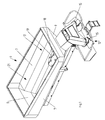
- Fig.1
- die als Großflächendüngerstreuer ausgebildete Verteilmaschine ohne Tragrahmen, Fahrwerk und Zugdeichsel in Prinzipdarstellung und in perspektivischer Darstellung in der Ansicht von schräg hinten,
- Fig.2
- den hinteren Bereich des Großflächendüngerstreuers in Prinzipdarstellung und in perspektivischer Darstellung in der Ansicht von schräg vorne,
- Fig.3
- den Großflächendüngerstreuer in Prinzipdarstellung, in Seitenansicht und im Schnitt III - III,
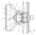
- Fig.4
- den Großflächendüngerstreuer in Prinzipdarstellung und in der Draufsicht und
- Fig.5
- den Großflächendüngerstreuer in Prinzipdarstellung und im Schnitt V - V.
- Die als Großflächendüngerstreuer ausgebildete Verteilmaschine weist den Tragrahmen 1, der sich über das Fahrwerk 2 mit den Laufrädern 3 und der Achse 4 im hinteren Bereich auf dem Boden und über die am vorderen Bereich des Tragrahmens 1 angeordnete Zugdeichsel 5 an einer Vorrichtung eines nicht dargestellten Ackerschleppers abstützt, auf. Auf dem Tragrahmen 1 ist der Vorratsbehälter 6 angeordnet und befestigt. Der Vorratsbehälter 6 weist die beiden seitlichen Vorratsbehälterwände 7 auf, die trichterförmig zueinander angeordnet sind. Weiterhin weist der Vorratsbehälter 6 eine vordere Vorratsbehälterwand 8 und eine hintere Vorratsbehälterwand 9 auf. Der Vorratsbehälter 6 weist einen Boden 10 auf, der als ein Transportband 11 zum Materialfördern aus in dem Behälter 6 enthaltenen körnigem Material zu einem am hinteren Ende des Transportbandes angeordneten Streuorgan 12. Dieses Streuorgan 12 weist zwei um aufrechte und beabstandet zueinander angeordnete Achsen rotierend angetriebene mit Wurfschaufeln besetzten Schleuderscheiben in nicht dargestellter Weise auf. Das Transportband 11 ist im unteren Bereich des Vorratsbehälters 6 angeordnet und als ein über Umlenkrollen 13 geführtes, umlaufend angetriebenes Förderband ausgebildet. Das Transportband 11 erstreckt sich über die gesamte untere Breite des Vorratsbehälters 6. In der hinteren Vorratsbehälterwand 9 ist eine Durchtrittsöffnung 14 angeordnet, durch welche das Förderband 11 das sich im Vorratsbehälter 6 befindliche körnige Material über Leiteinrichtungen 15 den Schleuderscheiben des Streuorgan 12 zuleitet.
- Im unteren und in Förderrichtung 16 des Transportbandes 11 gesehen, hinteren Bereich 17 des Vorratsbehälters 6 ist oberhalb des Transportbandes 11 ein das Transportband 11 in zwei im Abstand zueinander entstehende Förderbereiche 18 aufteilendes, dachförmig ausgebildetes und sich über den hinteren Teilbereich 10 der Länge des Vorratsbehälters 6 und des Transportbandes 11 erstreckendes Entlastungselement 19 angeordnet ist. Das Entlastungselement 19 sich von der der Zugdeichsel 5 abgewandten Endseite 20 des Vorratsbehälters 6 in Richtung der Zugdeichsel 5 über nicht mehr als % der Länge, vorzugsweise nicht mehr als die halbe Länge des Vorratsbehälters 6 oder Transportbandes als erstreckt, wie die Zeichnungen zeigen. Im Ausführungsbeispiel erstreckt sich das Entlastungselement 19 in Draufsicht bis über Achse 4 des Fahrwerkes 2 erstreckt. Somit ist in dem der Zugdeichsel 5 unmittelbar benachbarten Viertel, vorzugsweise Drittel der Länge des Vorratsbehälters 6 und/oder des Förderbandes als kein Entlastungselement 19 angeordnet ist.
- Erste Versuche haben gezeigt, dass es vorteilhaft ist, wenn sich das Entlastungselement 19 zumindest annähernd bis zur Achse oder Mittelachse des Fahrwerkes 2, jedoch über nicht mehr als ¾, vorzugsweise 2/3 der Länge des Vorratsbehälters 6 erstreckt.
- Durch die vorbeschriebene Anordnung des Entlastungselementes 19 in dem hinteren Bereich 17 des Vorratsbehälters 6 wird erreicht, dass das Material durch das Transportband 11 zunächst im vorderen Bereich 21 des Vorratsbehälters 6 entnommen und dem Streuorgan 12 zugeleitet wird. Hierdurch nimmt die von der Zugdeichsel 5 und Anhängerkupplung des die gezogene Verteilmaschine ziehenden Ackerschleppers aufzunehmende Stützlast ab. Somit ist sichergestellt, dass die Stützlast die zulässigen Werte nicht überschreitet. Hierbei ist die Länge des Entlastungselementes 19 so gewählt, dass nur soviel Material aus dem vorderen Bereich 21 des Vorratsbehälters 6 entnommen wird, dass keine negative Stützlast an der Zugdeichsel 5 auftritt. Damit keine negative Stützlast an der Deichsel auftritt, erstreckt sich das Entlastungselement in Draufsicht zumindest annähernd bis zur Achse des Fahrwerkes. Durch die erfindungsgemäße Anordnung des Entlastungselementes 19 wird bevorzugt aus dem vorderen Bereich 21 des Vorratsbehälters 6 das auszubringende Material von dem Transportband 11 entnommen und dem Streuorgan 12 zugeführt.
- In den Dachflächen des Entlastungselementes 19 sind mehrere Durchtrittsöffnungen 22 für das körnige Material angeordnet sind. Durch diese Durchtrittsöffnungen 22 kann Material, welches sich auf der Oberseite des Entlastungselementes 19 befindet, in Richtung des Transportbandes 11 hindurchtreten. Dieses ist insbesondere bei den ein schlechtes Rieselverhalten aufweisenden Materialien vorteilhaft. Hierdurch ist es möglich, dass durch die Durchtrittsöffnungen 22 Material im hinteren Bereich des Vorratsbehälters 6 nach unten hindurchtreten kann, so dass in kontrollierter Weise gleichzeitig neben dem bevorzugten Entnehmen aus dem vorderen Bereich 21 des Vorratsbehälters 6 auch aus dem hinteren Bereich 17 des Vorratsbehälters 6 in kontrollierter Weise Material von dem Transportband 11 in Richtung des Streuorgans 12 ausgetragen wird.
- Die vor erwähnten Durchtrittsöffnungen 22 in dem Entlastungselement 19 können durch Abdeckelemente 23 zumindest teilweise abdeckt oder verschlossen werden. In der
Fig. 2 sind zwei als Abdeckplättchen 23 ausgebildete Abdeckelemente beispielhaft dargestellt. Selbstverständlich können auch alle oder weitere Durchtrittsöffnungen 22 mit diesen Abdeckplättchen 23 abgedeckt oder verschlossen werden. Hierduch lässt sich die Zuführung des Materiales aus dem hinteren Bereich 17 bei dem bevorzugten Entnehmen des Materials aus dem vorderen Bereich 21 in gezielter Weise auf die verschiedenen Riesel- und Nachfließeigenschaften des auszubringenden Materials in einfacher Weise anpassen. Anstelle der Abdeckplättchen 23 können die Abdeckelemente in nicht dargestellter Weise als Verschlußstopfen ausgebildet sein. - In einer weiteren, nicht dargestellten Ausgestaltung können die Abdeckelemente 23 als eine Abdeckplatte ausgebildet sein. In dieser Ausgestaltung weist die Abdeckplatte eine dachförmige und an die Kontur des Entlastungselementes 19 angepasste Ausgestaltung auf.
Claims (8)
- Gezogene Verteilmaschine, insbesondere Düngerstreuer, insbesondere zum Ausbringen von körnigem Material, mit einem Rahmen (1), einem vorzugsweise einachsigem Fahrwerk (2) oder Tandemfahrwerk, einer Zugdeichsel (5) und einem auf dem Rahmen (1) befestigten Vorratsbehälter (6) und mit zumindest einem Streuorgan (12) zum Verteilen des Materials, welches auf der der Zugdeichsel (5) abgewandten Endseite (20) des Vorratsbehälters (6) angeordnet ist, und mit einem angetriebenen Transportband (11) zum Materialfördern zu dem auf der der Zugdeichsel (5) abgewandten Endseite (20) des Vorratsbehälters (6) angeordneten Streuorgan (12), wobei der Vorratsbehälter (6) als langgestreckter Behälter ausgebildet ist und im unteren Bereich des Vorratsbehälters (6) das über Umlenkrollen (13) geführte, umlaufende und sich über die gesamte untere Breite des Vorratsbehälters (6) erstreckende Transportband (11) angeordnet ist, wobei im unteren Bereich des Vorratsbehälters (6) oberhalb des Transportbandes (11) ein das Transportband (11) in zwei im Abstand zueinander entstehende Förderbereiche (18) aufteilendes, dachförmig ausgebildetes und sich über zumindest einen Teilbereich der Länge des Vorratsbehälters (6) und des Transportbandes (11) erstreckendes Entlastungselement (19) angeordnet ist, dadurch gekennzeichnet, dass das Entlastungselement (19) sich von der der Zugdeichsel (5) abgewandten Endseite des Vorratsbehälters (6) in Richtung der Zugdeichsel (5) über nicht mehr als % der Länge, vorzugsweise nicht mehr als die halbe Länge des Vorratsbehälters (6) oder Transportbandes erstreckt.
- Gezogene Verteilmaschine nach Anspruch 1, dadurch gekennzeichnet, dass sich das Entlastungselement (19) in Draufsicht zumindest annähernd bis zur Achse (4) oder Mittelachse des Fahrwerkes (2) erstreckt.
- Gezogene Verteilmaschine nach Anspruch 1, dadurch gekennzeichnet, dass in dem der Zugdeichsel (5) unmittelbar benachbarten Viertel, vorzugsweise Drittel der Länge des Vorratsbehälters (6) und/oder des Förderbandes (11) kein Entlastungselement (19) angeordnet ist.
- Gezogene Verteilmaschine nach zumindest einem der vorstehenden Ansprüche, dadurch gekennzeichnet, dass das Entlastungselement (19) sich zumindest annähernd bis zur Achse (4) oder Mittelachse des Fahrwerkes (2), jedoch über nicht mehr als ¾, vorzugsweise 2/3 der Länge des Vorratsbehälters (6) erstreckt.
- Gezogene Verteilmaschine nach zumindest einem der vorstehenden Ansprüche, dadurch gekennzeichnet, dass in den Dachflächen des Entlastungselementes (19) mehrere Durchtrittsöffnungen (22) für das körnige Material angeordnet sind.
- Gezogene Verteilmaschine nach zumindest einem der vorstehenden Ansprüche, dadurch gekennzeichnet, dass die Durchtrittsöffnungen (42) durch zumindest ein Abdeckelement (23) zumindest teilweise abdeckbar und/oder verschließbar sind.
- Gezogene Verteilmaschine Anspruch 6, dadurch gekennzeichnet, dass die Abdeckelemente als Verschlußstopfen ausgebildet sind.
- Gezogene Verteilmaschine Anspruch 6, dadurch gekennzeichnet, dass das Abdeckelement als Abdeckplatte, vorzugsweise als dachförmige und an die Kontur des Entlastungselementes angepasste Abdeckplatte ausgebildet ist.
Priority Applications (1)
| Application Number | Priority Date | Filing Date | Title |
|---|---|---|---|
| PL16401055T PL3143858T3 (pl) | 2015-09-18 | 2016-09-05 | Ciągnięta maszyna rozprowadzająca |
Applications Claiming Priority (1)
| Application Number | Priority Date | Filing Date | Title |
|---|---|---|---|
| DE102015115758.6A DE102015115758A1 (de) | 2015-09-18 | 2015-09-18 | Gezogene Verteilmaschine |
Publications (2)
| Publication Number | Publication Date |
|---|---|
| EP3143858A1 true EP3143858A1 (de) | 2017-03-22 |
| EP3143858B1 EP3143858B1 (de) | 2018-01-17 |
Family
ID=57003471
Family Applications (1)
| Application Number | Title | Priority Date | Filing Date |
|---|---|---|---|
| EP16401055.5A Active EP3143858B1 (de) | 2015-09-18 | 2016-09-05 | Gezogene verteilmaschine |
Country Status (4)
| Country | Link |
|---|---|
| EP (1) | EP3143858B1 (de) |
| DE (1) | DE102015115758A1 (de) |
| DK (1) | DK3143858T3 (de) |
| PL (1) | PL3143858T3 (de) |
Citations (8)
| Publication number | Priority date | Publication date | Assignee | Title |
|---|---|---|---|---|
| DE1459713A1 (de) * | 1962-07-20 | 1969-07-10 | Hanisch Dipl Ing Emil | Streugutfoerderer |
| DE2250808A1 (de) * | 1972-10-17 | 1974-05-02 | Amazonen Werke Dreyer H | Maschine zum ausbringen von gekoerntem und pulverfoermigem material |
| AU642245B2 (en) * | 1990-09-26 | 1993-10-14 | Ronald William Richmond | Sand and topsoil spreading machine |
| US5950933A (en) * | 1998-01-29 | 1999-09-14 | Balmer; Charles | Apparatus for spreading particulate materials having different components |
| DE4408016C2 (de) | 1994-03-10 | 2002-09-19 | Amazonen Werke Dreyer H | Düngerstreuer |
| WO2013106211A1 (en) * | 2011-12-30 | 2013-07-18 | Agco Corporation | Improving accuracy of fertilizer dispensed through a fixed opening |
| WO2013182700A1 (en) * | 2012-06-08 | 2013-12-12 | Ezy Technology Innovations Limited | Trailed hopper with mounting for a spreader |
| EP2799619A2 (de) * | 2013-04-12 | 2014-11-05 | ASTEC Mobile Machinery GmbH | Misch-Vorratsbehälter und Verfahren zum Homogenisieren von Material in einem solchen Misch-Vorratsbehälter |
-
2015
- 2015-09-18 DE DE102015115758.6A patent/DE102015115758A1/de not_active Ceased
-
2016
- 2016-09-05 EP EP16401055.5A patent/EP3143858B1/de active Active
- 2016-09-05 DK DK16401055.5T patent/DK3143858T3/en active
- 2016-09-05 PL PL16401055T patent/PL3143858T3/pl unknown
Patent Citations (8)
| Publication number | Priority date | Publication date | Assignee | Title |
|---|---|---|---|---|
| DE1459713A1 (de) * | 1962-07-20 | 1969-07-10 | Hanisch Dipl Ing Emil | Streugutfoerderer |
| DE2250808A1 (de) * | 1972-10-17 | 1974-05-02 | Amazonen Werke Dreyer H | Maschine zum ausbringen von gekoerntem und pulverfoermigem material |
| AU642245B2 (en) * | 1990-09-26 | 1993-10-14 | Ronald William Richmond | Sand and topsoil spreading machine |
| DE4408016C2 (de) | 1994-03-10 | 2002-09-19 | Amazonen Werke Dreyer H | Düngerstreuer |
| US5950933A (en) * | 1998-01-29 | 1999-09-14 | Balmer; Charles | Apparatus for spreading particulate materials having different components |
| WO2013106211A1 (en) * | 2011-12-30 | 2013-07-18 | Agco Corporation | Improving accuracy of fertilizer dispensed through a fixed opening |
| WO2013182700A1 (en) * | 2012-06-08 | 2013-12-12 | Ezy Technology Innovations Limited | Trailed hopper with mounting for a spreader |
| EP2799619A2 (de) * | 2013-04-12 | 2014-11-05 | ASTEC Mobile Machinery GmbH | Misch-Vorratsbehälter und Verfahren zum Homogenisieren von Material in einem solchen Misch-Vorratsbehälter |
Also Published As
| Publication number | Publication date |
|---|---|
| PL3143858T3 (pl) | 2018-06-29 |
| DK3143858T3 (en) | 2018-04-23 |
| EP3143858B1 (de) | 2018-01-17 |
| DE102015115758A1 (de) | 2017-03-23 |
Similar Documents
| Publication | Publication Date | Title |
|---|---|---|
| EP2832203B1 (de) | Sämaschine | |
| DE2805879A1 (de) | Verfahren fuer den einsatz von schleuderstreuern | |
| DE1966232A1 (de) | Bodenbearbeitungsmaschine | |
| EP3143858B1 (de) | Gezogene verteilmaschine | |
| DE2555011A1 (de) | Maschine zum ausbringen von korn- und pulverfoermigem gut | |
| DE102009026332A1 (de) | Verteiler für eine pneumatische Verteilmaschine | |
| DE102009026333A1 (de) | Verteiler für eine Verteilmaschine | |
| EP2353359B1 (de) | Landwirtschaftliche Vorrichtung | |
| DE2407061B2 (de) | Verteilergerät für landwirtschaftliche Zwecke | |
| DE102020133357A1 (de) | Dosiersystem einer landwirtschaftlichen Sämaschine | |
| DE3151581C2 (de) | Vorrichtung zum Austragen von Kalk oder dergl. auf in Reihen eingesäte Rüben oder dergl. | |
| DE102010000298A1 (de) | Zweischeibenstreuer | |
| DE10219210B4 (de) | Vorrichtung zum Ausbringen von Schüttgut | |
| EP2353360A1 (de) | Zentrifugalstreuer | |
| DE202019106565U1 (de) | Streuwagen | |
| EP3979781B1 (de) | Pneumatische saatgut- und/oder duengerverteilmaschine | |
| EP2052595A1 (de) | Sämaschine | |
| EP2353358B1 (de) | Landwirtschaftliche Vorrichtung | |
| EP3143857A1 (de) | Verteilmaschine | |
| DE102009012849A1 (de) | Pneumatische Direktsämaschine | |
| DE10262052B4 (de) | Vorrichtung zum Ausbringen von Schüttgut | |
| DE1918830C3 (de) | Fahrbarer Mineraldüngerstreuer | |
| DE2817543A1 (de) | Saemaschine, insbesondere drillmaschine | |
| DE1811301A1 (de) | Fahrzeug zum Streuen von pulverigem oder koernigem Streugut | |
| EP0958724B1 (de) | Düngerstreuer |
Legal Events
| Date | Code | Title | Description |
|---|---|---|---|
| PUAI | Public reference made under article 153(3) epc to a published international application that has entered the european phase |
Free format text: ORIGINAL CODE: 0009012 |
|
| AK | Designated contracting states |
Kind code of ref document: A1 Designated state(s): AL AT BE BG CH CY CZ DE DK EE ES FI FR GB GR HR HU IE IS IT LI LT LU LV MC MK MT NL NO PL PT RO RS SE SI SK SM TR |
|
| AX | Request for extension of the european patent |
Extension state: BA ME |
|
| 17P | Request for examination filed |
Effective date: 20170724 |
|
| RBV | Designated contracting states (corrected) |
Designated state(s): AL AT BE BG CH CY CZ DE DK EE ES FI FR GB GR HR HU IE IS IT LI LT LU LV MC MK MT NL NO PL PT RO RS SE SI SK SM TR |
|
| GRAP | Despatch of communication of intention to grant a patent |
Free format text: ORIGINAL CODE: EPIDOSNIGR1 |
|
| RIC1 | Information provided on ipc code assigned before grant |
Ipc: E01C 19/20 20060101ALN20170915BHEP Ipc: A01C 15/12 20060101AFI20170915BHEP Ipc: A01C 15/00 20060101ALN20170915BHEP |
|
| INTG | Intention to grant announced |
Effective date: 20171006 |
|
| RIC1 | Information provided on ipc code assigned before grant |
Ipc: A01C 15/12 20060101AFI20170925BHEP Ipc: E01C 19/20 20060101ALN20170925BHEP Ipc: A01C 15/00 20060101ALN20170925BHEP |
|
| GRAS | Grant fee paid |
Free format text: ORIGINAL CODE: EPIDOSNIGR3 |
|
| GRAA | (expected) grant |
Free format text: ORIGINAL CODE: 0009210 |
|
| AK | Designated contracting states |
Kind code of ref document: B1 Designated state(s): AL AT BE BG CH CY CZ DE DK EE ES FI FR GB GR HR HU IE IS IT LI LT LU LV MC MK MT NL NO PL PT RO RS SE SI SK SM TR |
|
| REG | Reference to a national code |
Ref country code: GB Ref legal event code: FG4D Free format text: NOT ENGLISH |
|
| REG | Reference to a national code |
Ref country code: CH Ref legal event code: EP |
|
| REG | Reference to a national code |
Ref country code: IE Ref legal event code: FG4D Free format text: LANGUAGE OF EP DOCUMENT: GERMAN |
|
| REG | Reference to a national code |
Ref country code: AT Ref legal event code: REF Ref document number: 963797 Country of ref document: AT Kind code of ref document: T Effective date: 20180215 |
|
| REG | Reference to a national code |
Ref country code: DE Ref legal event code: R096 Ref document number: 502016000470 Country of ref document: DE |
|
| REG | Reference to a national code |
Ref country code: NL Ref legal event code: FP |
|
| REG | Reference to a national code |
Ref country code: DK Ref legal event code: T3 Effective date: 20180420 |
|
| REG | Reference to a national code |
Ref country code: LT Ref legal event code: MG4D |
|
| PG25 | Lapsed in a contracting state [announced via postgrant information from national office to epo] |
Ref country code: NO Free format text: LAPSE BECAUSE OF FAILURE TO SUBMIT A TRANSLATION OF THE DESCRIPTION OR TO PAY THE FEE WITHIN THE PRESCRIBED TIME-LIMIT Effective date: 20180417 Ref country code: FI Free format text: LAPSE BECAUSE OF FAILURE TO SUBMIT A TRANSLATION OF THE DESCRIPTION OR TO PAY THE FEE WITHIN THE PRESCRIBED TIME-LIMIT Effective date: 20180117 Ref country code: LT Free format text: LAPSE BECAUSE OF FAILURE TO SUBMIT A TRANSLATION OF THE DESCRIPTION OR TO PAY THE FEE WITHIN THE PRESCRIBED TIME-LIMIT Effective date: 20180117 Ref country code: HR Free format text: LAPSE BECAUSE OF FAILURE TO SUBMIT A TRANSLATION OF THE DESCRIPTION OR TO PAY THE FEE WITHIN THE PRESCRIBED TIME-LIMIT Effective date: 20180117 Ref country code: ES Free format text: LAPSE BECAUSE OF FAILURE TO SUBMIT A TRANSLATION OF THE DESCRIPTION OR TO PAY THE FEE WITHIN THE PRESCRIBED TIME-LIMIT Effective date: 20180117 Ref country code: CY Free format text: LAPSE BECAUSE OF FAILURE TO SUBMIT A TRANSLATION OF THE DESCRIPTION OR TO PAY THE FEE WITHIN THE PRESCRIBED TIME-LIMIT Effective date: 20180117 |
|
| REG | Reference to a national code |
Ref country code: FR Ref legal event code: PLFP Year of fee payment: 3 |
|
| PG25 | Lapsed in a contracting state [announced via postgrant information from national office to epo] |
Ref country code: GR Free format text: LAPSE BECAUSE OF FAILURE TO SUBMIT A TRANSLATION OF THE DESCRIPTION OR TO PAY THE FEE WITHIN THE PRESCRIBED TIME-LIMIT Effective date: 20180418 Ref country code: BG Free format text: LAPSE BECAUSE OF FAILURE TO SUBMIT A TRANSLATION OF THE DESCRIPTION OR TO PAY THE FEE WITHIN THE PRESCRIBED TIME-LIMIT Effective date: 20180417 Ref country code: SE Free format text: LAPSE BECAUSE OF FAILURE TO SUBMIT A TRANSLATION OF THE DESCRIPTION OR TO PAY THE FEE WITHIN THE PRESCRIBED TIME-LIMIT Effective date: 20180117 Ref country code: IS Free format text: LAPSE BECAUSE OF FAILURE TO SUBMIT A TRANSLATION OF THE DESCRIPTION OR TO PAY THE FEE WITHIN THE PRESCRIBED TIME-LIMIT Effective date: 20180517 Ref country code: LV Free format text: LAPSE BECAUSE OF FAILURE TO SUBMIT A TRANSLATION OF THE DESCRIPTION OR TO PAY THE FEE WITHIN THE PRESCRIBED TIME-LIMIT Effective date: 20180117 Ref country code: RS Free format text: LAPSE BECAUSE OF FAILURE TO SUBMIT A TRANSLATION OF THE DESCRIPTION OR TO PAY THE FEE WITHIN THE PRESCRIBED TIME-LIMIT Effective date: 20180117 |
|
| PG25 | Lapsed in a contracting state [announced via postgrant information from national office to epo] |
Ref country code: MT Free format text: LAPSE BECAUSE OF FAILURE TO SUBMIT A TRANSLATION OF THE DESCRIPTION OR TO PAY THE FEE WITHIN THE PRESCRIBED TIME-LIMIT Effective date: 20180117 |
|
| REG | Reference to a national code |
Ref country code: DE Ref legal event code: R097 Ref document number: 502016000470 Country of ref document: DE |
|
| PG25 | Lapsed in a contracting state [announced via postgrant information from national office to epo] |
Ref country code: EE Free format text: LAPSE BECAUSE OF FAILURE TO SUBMIT A TRANSLATION OF THE DESCRIPTION OR TO PAY THE FEE WITHIN THE PRESCRIBED TIME-LIMIT Effective date: 20180117 Ref country code: AL Free format text: LAPSE BECAUSE OF FAILURE TO SUBMIT A TRANSLATION OF THE DESCRIPTION OR TO PAY THE FEE WITHIN THE PRESCRIBED TIME-LIMIT Effective date: 20180117 Ref country code: RO Free format text: LAPSE BECAUSE OF FAILURE TO SUBMIT A TRANSLATION OF THE DESCRIPTION OR TO PAY THE FEE WITHIN THE PRESCRIBED TIME-LIMIT Effective date: 20180117 |
|
| PLBE | No opposition filed within time limit |
Free format text: ORIGINAL CODE: 0009261 |
|
| STAA | Information on the status of an ep patent application or granted ep patent |
Free format text: STATUS: NO OPPOSITION FILED WITHIN TIME LIMIT |
|
| PG25 | Lapsed in a contracting state [announced via postgrant information from national office to epo] |
Ref country code: SM Free format text: LAPSE BECAUSE OF FAILURE TO SUBMIT A TRANSLATION OF THE DESCRIPTION OR TO PAY THE FEE WITHIN THE PRESCRIBED TIME-LIMIT Effective date: 20180117 Ref country code: SK Free format text: LAPSE BECAUSE OF FAILURE TO SUBMIT A TRANSLATION OF THE DESCRIPTION OR TO PAY THE FEE WITHIN THE PRESCRIBED TIME-LIMIT Effective date: 20180117 Ref country code: CZ Free format text: LAPSE BECAUSE OF FAILURE TO SUBMIT A TRANSLATION OF THE DESCRIPTION OR TO PAY THE FEE WITHIN THE PRESCRIBED TIME-LIMIT Effective date: 20180117 |
|
| 26N | No opposition filed |
Effective date: 20181018 |
|
| PG25 | Lapsed in a contracting state [announced via postgrant information from national office to epo] |
Ref country code: SI Free format text: LAPSE BECAUSE OF FAILURE TO SUBMIT A TRANSLATION OF THE DESCRIPTION OR TO PAY THE FEE WITHIN THE PRESCRIBED TIME-LIMIT Effective date: 20180117 |
|
| PG25 | Lapsed in a contracting state [announced via postgrant information from national office to epo] |
Ref country code: MC Free format text: LAPSE BECAUSE OF FAILURE TO SUBMIT A TRANSLATION OF THE DESCRIPTION OR TO PAY THE FEE WITHIN THE PRESCRIBED TIME-LIMIT Effective date: 20180117 |
|
| REG | Reference to a national code |
Ref country code: BE Ref legal event code: MM Effective date: 20180930 |
|
| REG | Reference to a national code |
Ref country code: IE Ref legal event code: MM4A |
|
| PG25 | Lapsed in a contracting state [announced via postgrant information from national office to epo] |
Ref country code: LU Free format text: LAPSE BECAUSE OF NON-PAYMENT OF DUE FEES Effective date: 20180905 |
|
| PG25 | Lapsed in a contracting state [announced via postgrant information from national office to epo] |
Ref country code: IE Free format text: LAPSE BECAUSE OF NON-PAYMENT OF DUE FEES Effective date: 20180905 |
|
| PG25 | Lapsed in a contracting state [announced via postgrant information from national office to epo] |
Ref country code: BE Free format text: LAPSE BECAUSE OF NON-PAYMENT OF DUE FEES Effective date: 20180930 |
|
| PG25 | Lapsed in a contracting state [announced via postgrant information from national office to epo] |
Ref country code: TR Free format text: LAPSE BECAUSE OF FAILURE TO SUBMIT A TRANSLATION OF THE DESCRIPTION OR TO PAY THE FEE WITHIN THE PRESCRIBED TIME-LIMIT Effective date: 20180117 |
|
| PG25 | Lapsed in a contracting state [announced via postgrant information from national office to epo] |
Ref country code: PT Free format text: LAPSE BECAUSE OF FAILURE TO SUBMIT A TRANSLATION OF THE DESCRIPTION OR TO PAY THE FEE WITHIN THE PRESCRIBED TIME-LIMIT Effective date: 20180117 |
|
| REG | Reference to a national code |
Ref country code: CH Ref legal event code: PL |
|
| PG25 | Lapsed in a contracting state [announced via postgrant information from national office to epo] |
Ref country code: HU Free format text: LAPSE BECAUSE OF FAILURE TO SUBMIT A TRANSLATION OF THE DESCRIPTION OR TO PAY THE FEE WITHIN THE PRESCRIBED TIME-LIMIT; INVALID AB INITIO Effective date: 20160905 Ref country code: MK Free format text: LAPSE BECAUSE OF NON-PAYMENT OF DUE FEES Effective date: 20180117 |
|
| PG25 | Lapsed in a contracting state [announced via postgrant information from national office to epo] |
Ref country code: CH Free format text: LAPSE BECAUSE OF NON-PAYMENT OF DUE FEES Effective date: 20190930 Ref country code: LI Free format text: LAPSE BECAUSE OF NON-PAYMENT OF DUE FEES Effective date: 20190930 |
|
| REG | Reference to a national code |
Ref country code: DE Ref legal event code: R081 Ref document number: 502016000470 Country of ref document: DE Owner name: AMAZONEN-WERKE H. DREYER SE & CO. KG, DE Free format text: FORMER OWNER: AMAZONEN-WERKE H. DREYER GMBH & CO. KG, 49205 HASBERGEN, DE |
|
| GBPC | Gb: european patent ceased through non-payment of renewal fee |
Effective date: 20200905 |
|
| PG25 | Lapsed in a contracting state [announced via postgrant information from national office to epo] |
Ref country code: GB Free format text: LAPSE BECAUSE OF NON-PAYMENT OF DUE FEES Effective date: 20200905 |
|
| REG | Reference to a national code |
Ref country code: AT Ref legal event code: MM01 Ref document number: 963797 Country of ref document: AT Kind code of ref document: T Effective date: 20210905 |
|
| PG25 | Lapsed in a contracting state [announced via postgrant information from national office to epo] |
Ref country code: AT Free format text: LAPSE BECAUSE OF NON-PAYMENT OF DUE FEES Effective date: 20210905 |
|
| P01 | Opt-out of the competence of the unified patent court (upc) registered |
Effective date: 20230523 |
|
| PGFP | Annual fee paid to national office [announced via postgrant information from national office to epo] |
Ref country code: PL Payment date: 20250612 Year of fee payment: 10 |
|
| PGFP | Annual fee paid to national office [announced via postgrant information from national office to epo] |
Ref country code: NL Payment date: 20250704 Year of fee payment: 10 |
|
| PGFP | Annual fee paid to national office [announced via postgrant information from national office to epo] |
Ref country code: DK Payment date: 20250911 Year of fee payment: 10 Ref country code: DE Payment date: 20250702 Year of fee payment: 10 |
|
| PGFP | Annual fee paid to national office [announced via postgrant information from national office to epo] |
Ref country code: IT Payment date: 20250825 Year of fee payment: 10 |
|
| PGFP | Annual fee paid to national office [announced via postgrant information from national office to epo] |
Ref country code: FR Payment date: 20250703 Year of fee payment: 10 |