EP3142868B1 - Rad und verfahren zum antreiben eines rades - Google Patents
Rad und verfahren zum antreiben eines rades Download PDFInfo
- Publication number
- EP3142868B1 EP3142868B1 EP15721675.5A EP15721675A EP3142868B1 EP 3142868 B1 EP3142868 B1 EP 3142868B1 EP 15721675 A EP15721675 A EP 15721675A EP 3142868 B1 EP3142868 B1 EP 3142868B1
- Authority
- EP
- European Patent Office
- Prior art keywords
- wheel
- hub
- ring
- wheel ring
- outer wheel
- Prior art date
- Legal status (The legal status is an assumption and is not a legal conclusion. Google has not performed a legal analysis and makes no representation as to the accuracy of the status listed.)
- Active
Links
Images
Classifications
-
- B—PERFORMING OPERATIONS; TRANSPORTING
- B60—VEHICLES IN GENERAL
- B60B—VEHICLE WHEELS; CASTORS; AXLES FOR WHEELS OR CASTORS; INCREASING WHEEL ADHESION
- B60B19/00—Wheels not otherwise provided for or having characteristics specified in one of the subgroups of this group
-
- B—PERFORMING OPERATIONS; TRANSPORTING
- B60—VEHICLES IN GENERAL
- B60B—VEHICLE WHEELS; CASTORS; AXLES FOR WHEELS OR CASTORS; INCREASING WHEEL ADHESION
- B60B9/00—Wheels of high resiliency, e.g. with conical interacting pressure-surfaces
- B60B9/18—Wheels of high resiliency, e.g. with conical interacting pressure-surfaces using fluid
- B60B9/24—Wheels of high resiliency, e.g. with conical interacting pressure-surfaces using fluid with pistons and cylinders
-
- B—PERFORMING OPERATIONS; TRANSPORTING
- B60—VEHICLES IN GENERAL
- B60B—VEHICLE WHEELS; CASTORS; AXLES FOR WHEELS OR CASTORS; INCREASING WHEEL ADHESION
- B60B9/00—Wheels of high resiliency, e.g. with conical interacting pressure-surfaces
- B60B9/26—Wheels of high resiliency, e.g. with conical interacting pressure-surfaces comprising resilient spokes
- B60B9/28—Wheels of high resiliency, e.g. with conical interacting pressure-surfaces comprising resilient spokes with telescopic action
-
- B—PERFORMING OPERATIONS; TRANSPORTING
- B60—VEHICLES IN GENERAL
- B60K—ARRANGEMENT OR MOUNTING OF PROPULSION UNITS OR OF TRANSMISSIONS IN VEHICLES; ARRANGEMENT OR MOUNTING OF PLURAL DIVERSE PRIME-MOVERS IN VEHICLES; AUXILIARY DRIVES FOR VEHICLES; INSTRUMENTATION OR DASHBOARDS FOR VEHICLES; ARRANGEMENTS IN CONNECTION WITH COOLING, AIR INTAKE, GAS EXHAUST OR FUEL SUPPLY OF PROPULSION UNITS IN VEHICLES
- B60K7/00—Disposition of motor in, or adjacent to, traction wheel
-
- F—MECHANICAL ENGINEERING; LIGHTING; HEATING; WEAPONS; BLASTING
- F03—MACHINES OR ENGINES FOR LIQUIDS; WIND, SPRING, OR WEIGHT MOTORS; PRODUCING MECHANICAL POWER OR A REACTIVE PROPULSIVE THRUST, NOT OTHERWISE PROVIDED FOR
- F03C—POSITIVE-DISPLACEMENT ENGINES DRIVEN BY LIQUIDS
- F03C1/00—Reciprocating-piston liquid engines
- F03C1/22—Reciprocating-piston liquid engines with movable cylinders or cylinder
- F03C1/24—Reciprocating-piston liquid engines with movable cylinders or cylinder in which the liquid exclusively displaces one or more pistons reciprocating in rotary cylinders
- F03C1/247—Reciprocating-piston liquid engines with movable cylinders or cylinder in which the liquid exclusively displaces one or more pistons reciprocating in rotary cylinders with cylinders in star- or fan-arrangement, the connection of the pistons with an actuated element being at the outer ends of the cylinders
Definitions
- the invention relates to a wheel, comprising an outer wheel ring, a hub and at least one support means with which the outer wheel ring is supported on the hub.
- the invention further relates to a method for operating such a wheel.
- combustion or electric motors For driving a wheel, for example, combustion or electric motors are known.
- Hydraulically or pneumatically operated motors are used in the prior art.
- muscle power, wind power or a downhill force to drive a wheel.
- Suspension and steering are usually realized by movable and / or pivotable, that is not rigidly connected to the vehicle shots for the rotatably mounted hub of the wheel.
- Braking is usually effected in internal combustion engines by converting kinetic energy into heat by means of brake discs or drums and friction linings.
- the braking is partly due to a reversal of the power flow and thus recovery of electrical energy (recuperation).
- other methods of recovering energy such as compressors or retarders.
- the US 3,672,458 , the GB 2 118 496 and the US 574.200 relate to vehicle wheels with metal cylinders as spokes, with by Zu- or. Passing a fluid into / out of the metal cylinders, the hub of the drive wheel can be moved out of the geometric center, so that a drive torque results.
- the DE 14 30 372 relates to a vehicle wheel drive, in which a drive wheel freely rotatably mounted on a stationary axle journal with a hub contains a plurality of separate, annular air chambers at its circumference.
- the US 1,759,833 relates to a drive device for a vehicle wheel.
- the invention has for its object to provide a wheel and a method for operating a wheel, which have an extended functionality.
- the wheel according to the invention is characterized in that an adjusting device (an adjusting mechanism) is provided, by means of which the hub, in particular during a rotation of the wheel, in particular continuously, relative to the outer wheel ring is adjustable.
- an adjusting device an adjusting mechanism
- the inventive method for the rotational driving of a wheel is characterized in that the hub for the rotational driving of the wheel, in particular continuously, relative to the outer wheel ring is adjusted.
- a basic idea of the invention is that the hub is not rigidly coupled to the wheel ring, but is adjustable in different directions relative to the outer wheel ring.
- an adjusting mechanism or an adjusting device is provided, which activates the hub moved relative to the outer ring, in particular in different radial directions.
- the outer wheel ring is preferably a rim, optionally with tires.
- the wheel ring has an outer tread, which may be formed for example by the rim itself or by the tire.
- the adjusting device is preferably a part of the support device, which supports the outer wheel ring on the hub. The adjusting device is thus preferably arranged between the hub and the outer wheel ring.
- the hub is actively displaced relative to the outer wheel ring and / or the outer wheel ring is actively moved relative to the hub, in particular in order to effect a rotation of the wheel by this displacement or movement.
- the adjusting device is thus configured to generate a force between the hub and the wheel ring, by means of which a deflection of the hub and / or the wheel ring (or a part thereof) can be effected.
- the force acting between hub and wheel ring can be used to rotate the wheel.
- the adjusting device acts on the support elements and can also be designed as a part of the support elements.
- the adjusting device is arranged to deflect the hub, in particular during the rotation of the wheel, in particular continuously, in different, in particular radial directions from a geometric center of the wheel.
- a leverage force is generated which causes a rotation of the wheel.
- the hub can then be moved continuously in different radial directions, so that the leverage force acts continuously.
- the adjusting device is arranged to move the hub both in different radial directions relative to the wheel ring and the hub steplessly adjusted by different amounts (distances) in the radial direction.
- the geometric center is preferably understood to be the geometric center or the geometric center of gravity, in particular with respect to the surface of the wheel extending transversely to the wheel axis. For a circular wheel, this is the center of the circle.
- the adjusting device is preferably arranged to move the hub along an orbit around a geometric center of the outer wheel ring.
- the adjusting device is adapted to generate in the fixed coordinate system of the rotating wheel, a movement of the hub along a circular path around the geometric center.
- the support means comprises a plurality, preferably at least three, support elements which extend between the hub and the wheel ring.
- the adjusting device is preferably arranged to change the length of the support elements between the hub and the wheel ring. It is particularly preferred if the adjusting device itself also supports the wheel ring on the hub or at least contributes to the support and thus can be regarded as part of the support device. Accordingly, it is preferred that the support elements each comprise the adjusting device, wherein the adjusting device is designed for adjusting the length of the support elements between the hub and the wheel ring.
- the support elements can preferably each be controlled individually, so that within a certain range of the wheel plane, an arbitrary positioning of the hub in the plane of the wheel can be adjusted. Thus, by varying the length of the individual support elements in the plane of the wheel in a certain area, the hub can be displaced or displaced as desired, in particular steplessly.
- the hub can selectively and actively deflect from the geometric center of the wheel, so that in conjunction with a force acting on the wheel (for example, the weight of a vehicle) torque is generated on the wheel.
- the adjusting device may be formed for example as a telescopic device.
- telescopic struts or spokes can be provided by means of a Lifting cylinder can be moved in and out.
- any other embodiments are conceivable which can move the hub by changing the length of the support elements in the wheel plane.
- variable-shape webs or spokes can be arranged between the hub and the wheel ring, wherein the mold can be actively changed, so that the hub is moved relative to the wheel ring.
- the adjusting device can be operated, for example, electromechanically and / or hydraulically and / or pneumatically. It is essential that not only a pure suspension or resilient mounting of the hub is provided, but the hub can actively against the wheel ring (or vice versa) can be moved.
- the spokes of the wheel for this electromechanical, hydraulic and / or pneumatically operated lifting cylinder include.
- the electromechanically, hydraulically and / or pneumatically operated adjusting device is used for adjustment, in particular for length and / or shape adjustment of the support elements.
- the support means comprises a plurality, preferably at least three, deformable support elements which extend between the hub and the wheel ring.
- the deformable, in particular elastic support elements allow a relative movement between the hub and the wheel ring.
- the adjusting device is preferably arranged to adjust the shape and / or the elasticity and / or the bias of the support elements, in particular independently of each other.
- the shape and / or the elasticity and / or prestressing of each individual support element can be changed individually, so that, for example by different elasticities of the individual support elements, a displacement of the hub relative to the wheel ring can be effected.
- the wheel ring is a dimensionally stable or rigid ring in the technical sense. It is therefore not intended that the shape of the wheel ring changed significantly. Of course, small deformations due to occurring loads (for example, the weight of a vehicle) are not excluded. It may therefore be a well-known in the basic art rim, such as a motor vehicle or a bicycle act. It is preferred that the adjusting device is arranged to adjust the position of the hub while maintaining the shape of the wheel ring. The hub is thus moved within the dimensionally stable wheel ring. For this purpose, for example, the support elements (spokes, webs or the like) controlled so adjusted or adjusted that although a movement of the hub takes place, a deformation of the wheel ring due to the adjustment of the support elements but omitted.
- the support elements spoke, webs or the like
- the adjusting device is set up to deform the outer wheel ring preferably continuously during the rotation of the wheel. This can be done actively by the adjusting mechanism or the adjusting device, for example, in a first transverse direction (first diameter direction, first half axis) a stronger shortening of the distance between the hub and the corresponding edge circumference than in a second transverse direction (second diameter direction, second half axis).
- first transverse direction first diameter direction, first half axis
- second diameter direction, second half axis second transverse direction
- the deformation can also take place independently of the support elements between hub and wheel ring, for example by deformation of a tire arranged on a rim.
- corresponding deformation elements can be arranged in the tire.
- the tread can be, for example, to the shape or contour of a substrate adjust on which the wheel rolls off.
- unevenness for example curbs, steps, etc.
- a local indentation in the region of an obstacle to be overcome for example an edge or step to be overcome, can be actively effected.
- a control device is provided, by means of which the adjusting mechanism or the adjusting device for the rotational driving of the wheel is controllable.
- the control device is preferably configured to continuously adjust the hub in the plane of the wheel and / or to change the contour of the wheel ring continuously.
- the relative movement between the hub and the wheel ring is preferably such that a force acting on the hub (for example, the weight of a vehicle) causes a rotation of the wheel.
- the wheel according to the invention can also be referred to as an active wheel or a wheel with a built-in drive mechanism, wherein the drive mechanism is a part of the wheel which rotates together with the wheel.
- the wheel is thus rotationally driven by the fact that the hub is adjusted relative to the wheel ring and / or the wheel ring is locally deformed. In this way, a lever force is created, which causes a rotation of the wheel. Hub and wheel are thus adjusted relative to each other so that the wheel is driven by rotation due to a lever force acting on the hub.
- the hub is actively moved along an orbit around a geometric center of the wheel ring.
- the wheel ring for rotationally driving the wheel can be continuously deformed, in particular such that the wheel ring is moved in an oval orbit around the hub.
- the adjustment for adjusting the hub and ring relative to each other or for the deformation of the wheel ring thus represents a drive means for the wheel.
- the drive is effected by an active deflection of the hub from the geometric center of the wheel and / or an active deformation of the Radrings such that the force acting on the hub is oblique to the line connecting the hub and contact point of the wheel.
- the wheel includes a rim located on the outer radius, possibly with tires, or a sprocket or a pulley (outer element, wheel ring). This is preferably round and rigid, but may optionally also be elastic and variable in its geometry.
- a hub (inner element) of the wheel is rotatably mounted on a shaft or axle. The hub is at least temporarily outside the geometric center of the wheel.
- Devices or means for transmitting electrical, pneumatic or hydraulic energy from the preferably stationary shaft to the rotating hub or rotating wheel may be provided.
- a control device for controlling the transmitted energy may be present.
- connecting elements for example three or more spokes or webs or other shaped connecting elements. These can be arranged in one or more rows (in the axial direction).
- the connecting elements may also be bent or crossed or arranged as scissors (similar to a lift truck) and may also be designed in the form of balls or cylinders.
- the connecting elements according to the invention can be both rigid and elastic.
- the connecting elements are actuators or "active elements".
- the connecting elements may be rigid and variable in their extent or shape (for example electromechanical, magnetic or hydraulic).
- the connecting elements may be elastic or variable in their preload and rigidity (for example pneumatically, for example pneumatic muscles; or electrically: active elements such as piezo-metal composites).
- the connecting elements exert a force between the hub and the outer element and thus cause a movement between them.
- the energy that is introduced into the connecting elements, in the propulsive power of the wheel implement. This happens in particular in that the hub is displaced using the active elements with respect to the geometric center of the outer element (rim).
- a force such as the weight of a vehicle, acts at the hub center along the vertical down and the position of the hub was shifted in the horizontal, creates a torque, since the reaction point, in this case, the Radaufstandsyak behind the hub center with the Force application point is located. The vehicle is thus rolling.
- the hub can be adjusted relative to the outer circumferential element in several, according to the invention in five degrees of freedom, which in addition to the drive control of track, camber, steering angle and / or a form of suspension can be provided.
- the suspension with appropriate control and an "active" damping conceivable.
- the further, sixth degree of freedom is the rotation about the axis of the shaft on which the hub is mounted.
- This degree of freedom could basically also be controlled with a corresponding drive shaft or a motor. However, this is no longer required by the invention for driving the wheel.
- the basic requirement for the conversion of energy into motion in the wheel according to the invention is a force acting externally on the circumference of the wheel and which is not completely compensated by a reaction force of the hub (or vice versa), since the vectors of both forces are not at the same point or not parallel to each other, so that an additional moment or another force follows, which may be, for example, the inertial force of a vehicle when accelerating or the frictional force (wind and / or rolling resistance) of a vehicle at high speeds.
- these forces would be the weight of the mass bearing on the axle or shaft and the reaction force at the wheel contact point on the road.
- these forces could come from, for example, a belt or chain running on the outer circumference, or even a radial force urging a gear on the outer periphery onto another gear.
- the driving force (and thus the acceleration) is proportional to the distance by which the hub center is adjusted relative to the wheel center (and thus the wheel contact point).
- the maximum driving force is limited to the value that can be achieved at maximum adjustment.
- the propulsive force is also proportional to the weight load on the axle, so that consequently the achievable acceleration is independent of the loading condition of the vehicle (provided that the actuators / active elements allow to apply the corresponding necessary forces).
- the achievable acceleration over all speed ranges of the wheel is constant (provided that the actuators / active elements allow the necessary energy throughput at the appropriate operating frequencies).
- an upper usable speed or operating frequency of the actuators defined, which may be comparatively high, for example, in metal piezoceramic elements.
- the drive concept according to the invention is in a range between an electric motor (largest moment in the state, approximately constant power output over the usable speed range) and internal combustion engine (with the speed increasing moment and correspondingly sharply increasing power output).
- the maximum force / acceleration is particularly dependent on the ratio of the maximum displacement of the hub to the radius of the wheel, that is independent of the wheel size.
- the upper limit of the acceleration is 1g (force max M * 1g).
- the power output or the power output increases linearly with the speed and the accelerating mass (if this also weighs on the wheel and not on a trailer with "passive wheels").
- the outer contour of the wheel does not necessarily have to be rigid and round.
- the entire outer contour of the wheel can be distorted in such a way that it appears, for example, as an inclined ellipse, with which a similar propulsion effect as described above can be achieved.
- the outer contour of the wheel could only be changed locally, for example by corresponding active elements within the belt of a tire, such that the tension conditions shift, for example, in the laces of the tire so that the effective force line is displaced in front of or behind the center of the hub , In this way, for example, the rolling resistance of a tire can be compensated. The energy needed to overcome the rolling resistance is thereby introduced into the active elements in the belt of the tire.
- the invention provides the possibility to combine the functions of suspension, damping, steering, drive and / or recuperation in a system which is arranged by means of actuators between an outer wheel and / or tire / rim and a rotatably mounted hub.
- This can be dispensed with further drives (such as an electric motor) in the system.
- further drives such as an electric motor
- the active elements or actuators can be realized for example by sickle-shaped spokes.
- the spokes may for example consist of a spring steel, which is coated on both sides with a piezoceramic, so that they want to increase or decrease their bending radius depending on the applied voltage in the piezo elements.
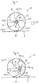
- a first embodiment of a wheel 10 according to the invention is in the Fig. 1 and 2 shown. It shows the Fig. 1 the wheel 10 in a rest position and the Fig. 2 in a drive position.
- the wheel 10 includes an outer wheel ring 20, such as a rim, which may be provided with a tire.
- the wheel ring 20 is circular and preferably rigid.
- the wheel 10 is shown on a bottom surface 2 and contacts the bottom surface 2 at a ground contact point 14.
- a hub 30 Inside the wheel 10 is a hub 30 with a bore 32 formed therein for receiving a shaft or axis.
- the shaft or axle may be rotationally rigidly coupled to or rotatably received within the hub 30.
- a support means 40 which in the illustrated embodiment, several, in particular five individual support members 42 has.
- the support members 42 are configured as crescent-shaped spokes and extend arcuately from an outer periphery of the hub 30 to an inner periphery of the wheel ring 20. Alternatively, a different number of support members 42 may be provided.
- the support elements 42 may also be offset from each other in the axial direction or arranged in several rows or planes.
- the geometric center of the wheel 10, in particular of the wheel ring 20, is identified by the reference numeral 12.
- a weight force is exerted on the wheel 10 which is directed vertically downwards from the center of the hub 30.
- the weight is marked F G.
- the hub 30 In the in Fig. 2 illustrated position, the hub 30 through the support members 42 actively from the center of the wheel 10, ie from the geometric center 12, deflected. In this way, the weight force F G no longer acts in the direction of the ground contact point 14, but forms a lever force, which drives the wheel 10 in a right-rolling movement.
- the hub 30 In order to drive the wheel 10 continuously, it is provided according to the invention that the hub 30 is actively moved by means of the support elements 40 in such a way that a corresponding leverage force continuously remains.
- the hub 30 is thus actively movable within the wheel ring 20 so that it describes a ring or circular path relative to the wheel ring 20.
- the round, ring or circular path is in the Fig. 2 represented by a dash-dotted line and identified by the reference numeral 18.
- the active displacement of the hub 30 relative to the wheel ring 20 takes place in accordance with the embodiment Fig. 1 and 2 by an active action on the individual support elements 42 of the support device 40 by the bias and / or elasticity of the individual support elements 42 is varied.
- This can be effected, for example, by the support elements 42 being coated on both sides with a piezoceramic, so that the bias voltage can be increased or reduced as a function of an applied electrical voltage.
- the control of the bias voltage by means of a only schematically in Fig. 1 indicated control device 50.
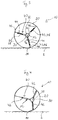
- the support members 42 are formed as telescopic spokes, which can be actively retracted and extended.
- the support members 42 are designed for this purpose as a lifting cylinder and include a cylinder 44 in which a piston 46 is guided with a piston rod.
- the lifting cylinder for example a pneumatic or hydraulic cylinder, is pivotably mounted on the hub 30 and / or the wheel ring 20.
- the supply of the operating medium is preferably carried out from the inside, that is, via the hub 30.
- the lifting cylinder forms an example of an adjusting device 48 according to the invention for adjusting the length of the support elements 42 between the hub 30 and wheel ring 20th
- Fig. 4 shows the wheel 10 accordingly Fig. 2 in a drive position in which a torque is applied to the wheel 10.
- the hub 30 is deflected out of the geometric center 12 by a corresponding adjustment of the individual support elements 42.
- the weight force F G does not point to the bottom contact point 14, so that a torque is exerted on the wheel 10.
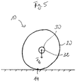
- Fig. 5 shows a further embodiment of a wheel according to the invention 10.
- the wheel ring 20 is made deformable, so that the outer contour of the wheel 10 can be deformed, for example, to an oval or an ellipse.
- the in the Fig. 5 Not shown support means 40 with support members 42 may, for example, analogous to the embodiments according to Fig. 1 to 4 be executed.
- the outer wheel ring 20 is stretched in a direction perpendicular to the vertical direction, which takes place by means of the support elements 42.
- the invention thus provides a wheel and a drive concept for a wheel, which enable a rotary driving of a wheel by active adjustment of the hub relative to the wheel ring and / or deformation of the wheel ring.
- the wheel according to the invention can be dispensed with, for example, an electric motor or an internal combustion engine for driving the wheel.
- the drive takes place in that arranged by between the hub and the wheel ring Supporting elements a varying force is applied, so that generated by a force acting on the hub, a lever and a torque is effected.
Description
- Die Erfindung betrifft ein Rad, aufweisend einen äußeren Radring, eine Nabe und mindestens eine Stützeinrichtung, mit welcher der äußere Radring an der Nabe abgestützt ist. Die Erfindung betrifft des Weiteren ein Verfahren zum Betreiben eines solchen Rades.
- Zum Antreiben eines Rades sind beispielsweise Verbrennungs- oder Elektromotoren bekannt. Die Übertragung der Kraft von dem Motor zum Rad erfolgt über sogenannte Antriebsstränge, beispielsweise ein Getriebe mit Wellen, Ketten, Riemen oder Ähnlichem. Auch hydraulisch oder pneumatisch arbeitende Motoren kommen im Stand der Technik zum Einsatz. Darüber hinaus ist es bekannt, zum Antreiben eines Rades Muskelkraft, Windkraft oder eine Hangabtriebskraft zu verwenden.
- Federung und Lenkung werden zumeist durch bewegliche und/oder schwenkbare, also durch nicht starr mit dem Fahrzeug verbundene Aufnahmen für die drehbar gelagerte Nabe des Rads realisiert.
- Das Bremsen wird in der Regel, bei Verbrennungsmotoren, durch Umwandlung kinetischer Energie in Wärme mit Hilfe von Bremsscheiben oder Trommeln und Reibbelägen bewirkt. Bei der Verwendung von Elektromotoren erfolgt das Bremsen zum Teil durch eine Umkehrung des Kraftflusses und damit Rückgewinnung elektrischer Energie (Rekuperation). Darüber hinaus sind weitere Verfahren zur Rückgewinnung von Energie bekannt, beispielsweise Kompressoren oder Retarder.
- Die
US-3,672,458 , dieGB 2 118 496 US-574,200 betreffen Fahrzeugräder mit Metallzylindern als Speichen, wobei durch Zu-bzw. Abführen eines Fluids in/aus den Metallzylindern die Nabe des Treibrads aus dem geometrischen Zentrum verschoben werden kann, sodass ein Antriebsmoment resultiert. - Die
DE 14 30 372 betrifft einen Fahrzeugradantrieb, bei dem ein mit einer Nabe frei drehbar auf einem feststehenden Achszapfen gelagertes Treibrad an seinem Umfang mehrere voneinander getrennte, ringförmige Luftkammern enthält. - Die
US-1,759,833 betrifft eine Antriebsvorrichtung für ein Fahrzeugrad. - Der Erfindung liegt die Aufgabe zugrunde, ein Rad und ein Verfahren zum Betreiben eines Rads bereitzustellen, welche eine erweiterte Funktionalität aufweisen.
- Die Aufgabe wird erfindungsgemäß durch ein Rad mit den Merkmalen des Anspruchs 1 und ein Verfahren zum Antreiben eines Rades mit den Merkmalen des Anspruchs 12 gelöst. Bevorzugte Ausgestaltungen sind in den abhängigen Ansprüchen angegeben.
- Das erfindungsgemäße Rad ist dadurch gekennzeichnet, dass eine Verstelleinrichtung (ein Verstellmechanismus) vorgesehen ist, mittels welcher die Nabe, insbesondere während einer Drehung des Rades, insbesondere kontinuierlich, relativ zum äußeren Radring verstellbar ist.
- Das erfindungsgemäße Verfahren zum drehenden Antreiben eines Rades ist dadurch gekennzeichnet, dass die Nabe zum drehenden Antreiben des Rades, insbesondere kontinuierlich, relativ zum äußeren Radring verstellt wird.
- Ein Grundgedanke der Erfindung besteht darin, dass die Nabe nicht starr mit dem Radring gekoppelt, sondern in unterschiedliche Richtungen gegenüber dem äußeren Radring verstellbar ist. Hierzu ist ein Verstellmechanismus beziehungsweise eine Verstelleinrichtung vorgesehen, welcher die Nabe aktiv gegenüber dem äußeren Radring bewegt, insbesondere in unterschiedliche radiale Richtungen. Der äußere Radring ist bevorzugt eine Felge, gegebenenfalls mit Reifen. Der Radring weist eine äußere Lauffläche auf, die zum Beispiel durch die Felge selbst oder durch den Reifen gebildet sein kann. Die Verstelleinrichtung ist bevorzugt ein Teil der Stützeinrichtung, welche den äußeren Radring an der Nabe abstützt. Die Verstelleinrichtung ist also bevorzugt zwischen der Nabe und dem äußeren Radring angeordnet. Durch die Verstelleinrichtung wird die Nabe aktiv relativ zu dem äußeren Radring verschoben und/oder der äußere Radring aktiv relativ zur Nabe bewegt, insbesondere, um durch diese Verschiebung beziehungsweise Bewegung eine Drehung des Rades zu bewirken. Die Verstelleinrichtung ist also eingerichtet, eine Kraft zwischen der Nabe und dem Radring zu erzeugen, mittels welcher eine Auslenkung der Nabe und/oder des Radrings (oder eines Teils hiervon) bewirkbar ist. Die zwischen Nabe und Radring wirkende Kraft kann zum drehenden Antreiben des Rades verwendet werden. Die Verstelleinrichtung wirkt auf die Stützelemente und kann auch als ein Teil der Stützelemente ausgebildet sein.
- In einer bevorzugten Ausführungsform ist vorgesehen, dass die Verstelleinrichtung eingerichtet ist, die Nabe, insbesondere während der Drehung des Rades, insbesondere kontinuierlich, in unterschiedliche, insbesondere radiale Richtungen aus einem geometrischen Zentrum des Rades auszulenken. Durch die Auslenkung aus dem geometrischen Zentrum wird, insbesondere, wenn die Auslenkung schräg zu einer auf das Rad wirkenden Kraft erfolgt, eine Hebelkraft erzeugt, die eine Drehung des Rads bewirkt. Zum kontinuierlichen Antreiben des Rads kann die Nabe dann kontinuierlich in unterschiedliche radiale Richtungen bewegt werden, so dass die Hebelkraft kontinuierlich wirkt. Vorzugsweise ist die Verstelleinrichtung eingerichtet, die Nabe sowohl in unterschiedliche radiale Richtungen relativ zum Radring zu bewegen als auch die Nabe stufenlos um unterschiedliche Beträge (Strecken) in radialer Richtung zu verstellen. Unter dem geometrischen Zentrum wird vorzugsweise der geometrische Mittelpunkt oder der geometrische Schwerpunkt, insbesondere bezogen auf die quer zur Radachse verlaufende Fläche des Rades verstanden. Bei einem kreisrunden Rad ist dies der Kreismittelpunkt. Mathematisch lässt sich der Schwerpunkt beziehungsweise Mittelpunkt durch Mittelung aller Punkte der von dem Radring begrenzten Fläche des Rades ermitteln.
- Die Verstelleinrichtung ist vorzugsweise eingerichtet, die Nabe entlang einer Umlaufbahn um ein geometrisches Zentrum des äußeren Radrings zu bewegen. Vorzugsweise ist die Verstelleinrichtung eingerichtet, im feststehenden Koordinatensystem des sich drehenden Rades eine Bewegung der Nabe entlang einer Kreisbahn um das geometrische Zentrum zu erzeugen.
- Erfindungsgemäß weist die Stützeinrichtung mehrere, vorzugsweise mindestens drei Stützelemente auf, die sich zwischen der Nabe und dem Radring erstrecken. Die Verstelleinrichtung ist vorzugsweise eingerichtet, die Länge der Stützelemente zwischen der Nabe und dem Radring zu verändern. Besonders bevorzugt ist es, wenn die Verstelleinrichtung selbst auch den Radring an der Nabe abstützt oder zumindest zur Abstützung beiträgt und somit als Teil der Stützeinrichtung angesehen werden kann. Dementsprechend is es bevorzugt, dass die Stützelemente jeweils die Verstelleinrichtung umfassen, wobei die Verstelleinrichtung zur Einstellung der Länge der Stützelemente zwischen der Nabe und dem Radring ausgebildet ist. Dabei lassen sich die Stützelemente vorzugsweise jeweils einzeln ansteuern, so dass innerhalb eines bestimmten Bereichs der Radebene eine beliebige Positionierung der Nabe in der Ebene des Rades eingestellt werden kann. Die Nabe lässt sich also durch Variierung der Länge der einzelnen Stützelemente in der Ebene des Rades in einem bestimmten Bereich beliebig, insbesondere stufenlos, verschieben beziehungsweise verstellen.
- Durch die auf diese Weise längenverstellbaren Stützelemente (beispielsweise Speichen und/oder Streben) lässt sich die Nabe gezielt und aktiv aus dem geometrischen Zentrum des Rades auslenken, so dass im Zusammenspiel mit einer auf das Rad wirkenden Kraft (beispielsweise die Gewichtskraft eines Fahrzeugs) ein Drehmoment auf das Rad erzeugt wird. Die Verstelleinrichtung kann beispielsweise als Teleskopeinrichtung ausgebildet sein. Beispielsweise können teleskopierbare Streben oder Speichen vorgesehen sein, die mittels eines Hubzylinders ein- und ausgefahren werden können. Grundsätzlich sind aber auch beliebige andere Ausführungsformen denkbar, welche die Nabe durch eine Veränderung der Länge der Stützelemente in der Radebene bewegen können. Beispielsweise können formveränderliche Stege oder Speichen zwischen der Nabe und dem Radring angeordnet werden, wobei die Form aktiv verändert werden kann, so dass die Nabe relativ zum Radring bewegt wird.
- Die Verstelleinrichtung kann beispielsweise elektromechanisch und/oder hydraulisch und/oder pneumatisch betrieben sein. Wesentlich ist, dass nicht nur eine reine Federung beziehungsweise federnde Lagerung der Nabe vorgesehen ist, sondern die Nabe aktiv gegenüber dem Radring (oder umgekehrt) bewegt werden kann. Beispielsweise können die Speichen des Rades hierzu elektromechanisch, hydraulisch und/oder pneumatisch betriebene Hubzylinder umfassen. Die elektromechanisch, hydraulisch und/oder pneumatisch betriebene Verstelleinrichtung dient zur Verstellung, insbesondere zur Längen- und/oder Formverstellung der Stützelemente.
- In einer weiteren bevorzugten Ausführungsform weist die Stützeinrichtung mehrere, vorzugsweise mindestens drei verformbare Stützelemente auf, die sich zwischen der Nabe und dem Radring erstrecken. Die verformbaren, insbesondere elastischen Stützelemente erlauben eine Relativbewegung zwischen Nabe und Radring. Zum aktiven Verstellen der Nabe ist die Verstelleinrichtung vorzugsweise eingerichtet, die Form und/oder die Elastizität und/oder die Vorspannung der Stützelemente, insbesondere unabhängig voneinander zu verstellen. Es lässt sich also die Form und/oder die Elastizität und/oder Vorspannung jedes einzelnen Stützelements einzeln verändern, so dass, beispielsweise durch unterschiedliche Elastizitäten der einzelnen Stützelemente, eine Verlagerung der Nabe relativ zum Radring bewirkt werden kann. Hierzu drückt beispielsweise ein erstes Stützelement die Nabe stärker zur gegenüberliegenden Seite des Radrings als ein zweites Stützelement. Durch kontinuierliche Änderungen der Formen, Elastizitäten beziehungsweise Vorspannungen der Stützelemente kann eine "Wanderung" der Nabe innerhalb des Radrings erzeugt werden.
- In einer bevorzugten Ausführungsform handelt es sich bei dem Radring um einen im technischen Sinn formstabilen beziehungsweise steifen Ring. Es ist also nicht vorgesehen, dass sich die Form des Radrings wesentlich verändert. Dabei sind selbstverständlich geringe Verformungen aufgrund auftretender Lasten (beispielsweise die Gewichtskraft eines Fahrzeugs) nicht ausgeschlossen. Es kann sich also um eine in der grundsätzlichen Art bekannte Felge, beispielsweise eines Kraftfahrzeugs oder eines Fahrrads, handeln. Dabei ist es bevorzugt, dass die Verstelleinrichtung eingerichtet ist, die Position der Nabe unter Beibehaltung der Form des Radrings zu verstellen. Die Nabe wird also innerhalb des formstabilen Radrings bewegt. Hierzu werden beispielsweise die Stützelemente (Speichen, Stege oder Ähnliches) derart gesteuert verstellt beziehungsweise angepasst, dass zwar eine Bewegung der Nabe erfolgt, eine Verformung des Radrings aufgrund der Verstellung der Stützelemente aber unterbleibt.
- In einer weiteren bevorzugten Ausführungsform kann vorgesehen sein, dass die Verstelleinrichtung eingerichtet ist, den äußeren Radring während der Drehung des Rades vorzugsweise kontinuierlich zu verformen. Dies kann aktiv durch den Verstellmechanismus beziehungsweise die Verstelleinrichtung erfolgen, indem beispielsweise in einer ersten Querrichtung (erste Durchmesserrichtung, erste Halbachse) eine stärkere Verkürzung des Abstands zwischen Nabe und entsprechendem Randumfang erfolgt als in einer zweiten Querrichtung (zweite Durchmesserrichtung, zweite Halbachse). Auf diese Weise kann beispielsweise eine Verformung des Radrings in einer Weise erfolgen, dass der äußere Radring auf einer ovalen, insbesondere elliptischen Umlaufbahn um eine Zentralachse bewegt wird. Es erfolgt also vorzugsweise eine lokale Verformung des Radrings, die entlang des Umfangs unterschiedlich ist. Grundsätzlich kann die Verformung auch unabhängig von den Stützelementen zwischen Nabe und Radring erfolgen, beispielsweise durch eine Verformung eines auf einer Felge angeordneten Reifens. Hierzu können in dem Reifen entsprechende Verformungselemente angeordnet sein.
- Durch die Verformung des Radrings (Felge und/oder Reifen) lässt sich die Lauffläche beispielsweise an die Form beziehungsweise Kontur eines Untergrunds anpassen, auf welchem das Rad abrollt. So können beispielsweise Unebenheiten (zum Beispiel Bordsteinkanten, Stufen etc.) leichter überwunden werden. Hierzu kann gegebenenfalls aktiv eine lokale Einformung im Bereich eines zu überwindenden Hindernisses, beispielsweise einer zu überwindenden Kante oder Stufe, bewirkt werden.
- Besonders bevorzugt ist es nach der Erfindung, dass eine Steuerungseinrichtung vorhanden ist, mittels welcher der Verstellmechanismus beziehungsweise die Verstelleinrichtung zum drehenden Antreiben des Rades steuerbar ist. Die Steuerungseinrichtung ist vorzugsweise eingerichtet, die Nabe kontinuierlich in der Ebene des Rades zu verstellen und/oder die Kontur des Radrings kontinuierlich zu verändern. Die Relativbewegung zwischen Nabe und Radring erfolgt vorzugsweise derart, dass eine auf die Nabe wirkende Kraft (beispielsweise die Gewichtskraft eines Fahrzeugs) eine Drehung des Rads bewirkt.
- Das erfindungsgemäße Rad kann auch als ein aktives Rad beziehungsweise ein Rad mit einem eingebauten Antriebsmechanismus bezeichnet werden, wobei der Antriebsmechanismus ein Teil des Rads ist, welcher sich zusammen mit dem Rad dreht. Das Rad wird also dadurch drehend angetrieben, dass die Nabe gegenüber dem Radring verstellt und/oder der Radring lokal verformt wird. Auf diese Weise entsteht eine Hebelkraft, die eine Drehung des Rads bewirkt. Nabe und Radring werden also derart relativ zueinander verstellt, dass das Rad aufgrund einer Hebelkraft, die auf die Nabe wirkt, drehend angetrieben wird. Hierbei ist es bevorzugt, dass die Nabe aktiv entlang einer Umlaufbahn um ein geometrisches Zentrum des Radrings bewegt wird. Alternativ oder zusätzlich kann der Radring zum drehenden Antreiben des Rades kontinuierlich verformt werden, insbesondere derart, dass der Radring auf einer ovalen Umlaufbahn um die Nabe bewegt wird.
- Die Verstelleinrichtung zur Verstellung von Nabe und Radring relativ zueinander beziehungsweise zur Verformung des Radrings stellt also eine Antriebseinrichtung für das Rad dar. Der Antrieb erfolgt durch ein aktives Auslenken der Nabe aus dem geometrischen Mittelpunkt des Rades und/oder ein aktives Verformen des Radrings derart, dass die auf die Nabe wirkende Kraft schräg zu der Verbindungslinie zwischen Nabe und Aufstandspunkt des Rads verläuft.
- Die Erfindung kann auch folgendermaßen beschrieben werden:
Das Rad umfasst eine am äußeren Radius befindliche Felge, gegebenenfalls mit Reifen, oder einen Zahnkranz oder eine Riemenscheibe (äußeres Element, Radring). Dieses ist vorzugsweise rund und starr, kann gegebenenfalls aber auch elastisch und in seiner Geometrie veränderlich sein. Eine Nabe (inneres Element) des Rades ist auf einer Welle oder Achse drehbar gelagert. Die Nabe befindet sich zumindest zeitweise außerhalb der geometrischen Mitte des Rades. Es können Vorrichtungen oder Mittel zur Übertragung von elektrischer, pneumatischer oder hydraulischer Energie von der vorzugsweise stehenden Welle in die sich drehende Nabe beziehungsweise das sich drehende Rad vorgesehen sein. Des Weiteren kann eine Steuereinrichtung zur Steuerung der übertragenen Energie vorhanden sein. - Zwischen der Nabe (inneres Element) und dem äußeren Element sind Verbindungselemente, beispielsweise drei oder mehr Speichen oder Stege oder andersartig geformte, verbindende Elemente vorgesehen. Diese können ein- oder mehrreihig (in axialer Richtung) angeordnet sein. Die Verbindungselemente können außerdem gebogen oder gekreuzt oder als Scheren (ähnlich einem Hubwagen) angeordnet sein und können auch in Form von Kugeln oder Zylindern ausgeführt sein. Die verbindenden Elemente können erfindungsgemäß sowohl starr also auch elastisch sein.
- Ein Aspekt der Erfindung besteht darin, dass die verbindenden Elemente Aktuatoren oder "aktive Elemente" sind. Die Verbindungselemente können starr und in ihrer Ausdehnung oder ihre Form veränderlich sein (beispielsweise elektromechanisch, magnetisch oder hydraulisch). Außerdem können die Verbindungselemente elastisch oder in ihrer Vorspannung und Steifigkeit veränderlich sein (beispielsweise pneumatisch, zum Beispiel pneumatische Muskeln; oder elektrisch: aktive Elemente wie Piezo-Metall-Komposite).
- Die Verbindungselemente üben eine Kraft zwischen der Nabe und dem äußeren Element aus und bewirken somit eine Bewegung zwischen diesen. Durch eine kontinuierliche Bewegung lässt sich die Energie, welche in die Verbindungselemente eingebracht wird, in Vortriebsleistung des Rades umsetzen. Dies geschieht insbesondere dadurch, dass die Nabe unter Einsatz der aktiven Elemente gegenüber der geometrischen Mitte des äußeren Elements (Felge) verschoben wird. Wenn nun eine Kraft, beispielsweise die Gewichtskraft eines Fahrzeugs, an der Nabenmitte entlang der Senkrechten nach unten wirkt und die Position der Nabe in der Horizontalen verschoben wurde, entsteht ein Drehmoment, da der Reaktionspunkt, in diesem Fall der Radaufstandspunkt, hinter der Nabenmitte mit dem Kraftangriffspunkt liegt. Das Fahrzeug kommt somit ins Rollen. Werden die Aktuatoren (unter Einspeisung von Energie) so angesteuert, dass die Nabenmitte im nicht mitdrehenden Koordinatensystem stets dieselbe Position relativ zur Lage des Ursprungs des drehenden Koordinatensystems des äußeren Rades beziehungsweise Radelements behält, bleibt dieses Antriebsmoment auch unter Drehung des Rades, unabhängig von dessen Geschwindigkeit, aufrecht erhalten. Ein Fahrzeug in der Ebene wird also fortgesetzt "virtuell bergab rollen". Im mitdrehenden Koordinatensystem des Rades beziehungsweise des äußeren Radelements (Radring) würde die Nabe eine Kreisbahn beschreiben, ohne sich aber selbst zu drehen. Bei Umkehrung des Prinzips, also Verschiebung der Nabenmitte hinter den Radaufstandspunkt, wird eine Verzögerung erreicht, wobei auch eine Rekuperation von Energie möglich ist. Durch entsprechende dreidimensionale Anordnung der Stützelemente (aktive Elemente), beispielsweise 2x3 Elemente in zwei Ebenen, lässt sich die Nabe relativ zum umlaufenden äußeren Element in mehreren, erfindungsgemäß in fünf Freiheitsgraden verstellen, wodurch zusätzlich zum Antrieb eine Kontrolle von Spur, Sturz, Lenkwinkel und/oder eine Form der Federung bereitgestellt werden kann. Hinsichtlich der Federung ist mit entsprechender Steuerung auch eine "aktive" Dämpfung denkbar.
- Der weitere, sechste Freiheitsgrad ist die Drehung um die Achse der Welle, auf der die Nabe gelagert ist. Dieser Freiheitsgrad ließe sich grundsätzlich auch mit einer entsprechenden Antriebswelle beziehungsweise einem Motor kontrollieren. Dieser ist aber durch die Erfindung zum Antrieb des Rades nicht mehr erforderlich.
- Grundvoraussetzung für die Umwandlung von Energie in Bewegung ist bei dem erfindungsgemäßen Rad eine Kraft, die von außen auf den Umfang des Rades wirkt und die von einer Reaktionskraft der Nabe (oder umgekehrt) nicht vollständig kompensiert wird, da die Vektoren beider Kräfte nicht auf denselben Punkt zeigen oder nicht parallel zueinander liegen, so dass ein zusätzliches Moment oder eine weitere Kraft folgt, die beispielsweise die Trägheitskraft eines Fahrzeugs beim Beschleunigen oder die Reibkraft (Wind- und/oder Rollwiderstand) eines Fahrzeugs bei schneller Fahrt sein kann. Bei einer Anwendung an einem Fahrzeug wären dies die Schwerkraft der Masse, die auf der Achse oder Welle lastet, und die Reaktionskraft am Radaufstandspunkt auf der Straße. Bei einer Anwendung zum Antrieb einer Maschine könnten diese Kräfte beispielsweise von einem Riemen oder einer Kette kommen, die auf dem äußeren Umfang laufen, oder auch von einer Radialkraft, mit der eine Verzahnung am äußeren Umfang auf ein weiteres Zahnrad gedrückt wird.
- Beim Einsatz als Lauf- und Antriebsrad an einem Fahrzeug ist die Vortriebskraft (und damit die Beschleunigung) proportional abhängig vom Weg, um den die Nabenmitte gegenüber der Radmitte (und damit dem Radaufstandspunkt) verstellt wird. Damit ist die maximale Antriebskraft begrenzt auf den Wert, der bei maximaler Verstellung erreicht werden kann. Die Vortriebskraft ist zudem proportional zu der auf der Achse lastenden Gewichtskraft, so dass in der Folge die erreichbare Beschleunigung unabhängig vom Beladungszustand des Fahrzeugs ist (unter der Voraussetzung, dass die Aktoren/aktiven Elemente es erlauben, die entsprechend notwendigen Kräfte aufzubringen). Darüber hinaus ist die erreichbare Beschleunigung über alle Drehzahlbereiche des Rades konstant (vorausgesetzt, die Aktoren/aktiven Elemente erlauben den dazu notwendigen Energiedurchsatz bei den entsprechenden Arbeitsfrequenzen). Vorzugsweise wird jedoch eine obere nutzbare Drehzahl beziehungsweise Arbeitsfrequenz der Aktoren definiert, wobei diese beispielsweise bei Metall-Piezokeramikelementen vergleichsweise hoch liegen kann.
- Von der Charakteristik her liegt das erfindungsgemäße Antriebskonzept in einem Bereich zwischen einem Elektromotor (größtes Moment im Stand, annähernd konstante Leistungsabgabe über den nutzbaren Drehzahlbereich) und Verbrennungsmotor (mit der Drehzahl steigendes Moment und entsprechend stark steigende Leistungsabgabe).
- Die maximale Kraft/Beschleunigung ist insbesondere vom Verhältnis des maximalen Verstellweges der Nabe zum Radius des Rades abhängig, also unabhängig von der Radgröße. Im theoretischen Idealfall ist die Obergrenze der Beschleunigung 1g (Kraft max. M * 1g).
- Die Leistungsabgabe beziehungsweise der Leistungsumsatz steigt linear mit der Drehzahl und mit der beschleunigenden Masse (sofern diese auch auf dem Rad lastet und nicht etwa auf einem Anhänger mit "passiven Rädern").
- Die äußere Kontur des Rades muss nicht zwangsläufig starr und rund sein. Beispielsweise kann vorgesehen sein, dass sich die gesamte Außenkontur des Rades in einer Weise verziehen lässt, dass diese beispielsweise als geneigte Ellipse erscheint, womit ein ähnlicher Vortriebseffekt wie oben beschrieben erreicht werden kann. Zum anderen könnte die Außenkontur des Rades nur lokal, also beispielsweise durch entsprechende aktive Elemente innerhalb des Gürtels eines Reifens, so verändert werden, dass sich die Spannungsverhältnisse zum Beispiele im Latsch des Reifens so verschieben, dass die wirksame Kraftlinie vor oder hinter die Nabenmitte verlagert wird. Auf diese Weise kann beispielsweise der Rollwiderstand eines Reifens kompensiert werden. Die Energie, die zur Überwindung des Rollwiderstands nötig ist, wird dabei in die aktiven Elemente im Gürtel des Reifens eingebracht. Auf diese Weise kann man ein System erhalten, dass auch bei Last und größerer Nachgiebigkeit des Reifens scheinbar reibungsfrei hin und her gerollt werden könnte. In einer weiteren bevorzugten Ausführungsform könnte mit einer Sensorik, die die Umgebung im Vorfeld abtastet, durch aktive Elemente die Kontur eines Reifens oder Rades in der Form an Hindernisse, wie zum Beispiel Treppen oder Bordsteinkanten angepasst werden. Diese könnten somit ohne Mühe überwunden werden.
- Weiterhin wäre es bei entsprechender Ansteuerung der Aktuatoren auch möglich, aus oszillierenden Bewegungen - der entweder starr oder auch beweglich mit dem Fahrzeug oder dem Maschinenteil verbundenen - Welle/Achse (auf welcher die Nabe läuft) Energie in Antriebs- beziehungsweise Vortriebsleistung zu transformieren.
- Durch die Erfindung ergibt sich die Möglichkeit, die Funktionen von Federung, Dämpfung, Lenkung, Antrieb und/oder Rekuperation in einem System, welches mittels Aktuatoren zwischen einem äußeren Rad und/oder Reifen/Felge und einer drehbar gelagerten Nabe angeordnet ist, zu vereinen. Hierbei kann auf weitere Antriebe (wie beispielsweise ein Elektromotor) im System verzichtet werden. Beispielsweise ist es möglich, ein Antriebssystem bereitzustellen, das vollkommen ohne drehende Teile auskommt (abgesehen von der drehenden Lagerung der Nabe).
- Die aktiven Elemente beziehungsweise Aktoren können beispielsweise durch sichelförmige Speichen realisiert werden. Die Speichen können beispielsweise aus einem Federstahl bestehen, welcher beidseitig mit einer Piezokeramik beschichtet ist, so dass sie ihren Biegeradius je nach anliegender Spannung in den Piezoelementen vergrößern oder verringern möchten.
- Die Erfindung wird nachfolgend anhand von bevorzugten Ausführungsformen, welche in den beiliegenden, schematischen Figuren dargestellt sind, weiter beschrieben. In den Figuren zeigt:
- Fig. 1
- eine erste Ausführungsform eines erfindungsgemäßen Rades in einer Ruhestellung;
- Fig. 2
- das Rad aus
Fig. 1 in einer in einer Antriebsstellung; - Fig. 3
- eine zweite Ausführungsform eines erfindungsgemäßen Rades in einer Ruhestellung;
- Fig. 4
- das Rad aus
Fig. 3 in einer in einer Antriebsstellung; und - Fig. 5
- eine dritte Ausführungsform eines erfindungsgemäßen Rades.
- Gleiche oder gleich wirkende Komponenten sind in sämtlichen Figuren mit denselben Bezugszeichen gekennzeichnet. Die anhand der einzelnen Figuren beziehungsweise Ausführungsformen beschriebenen Merkmale können, soweit technisch möglich, auch miteinander kombiniert werden.
- Eine erste Ausführungsform eines erfindungsgemäßen Rades 10 ist in den
Fig. 1 und 2 gezeigt. Dabei zeigt dieFig. 1 das Rad 10 in einer Ruhestellung und dieFig. 2 in einer Antriebsstellung. Das Rad 10 umfasst einen äußeren Radring 20, beispielsweise eine Felge, die mit einem Reifen versehen sein kann. Der Radring 20 ist kreisförmig gestaltet und vorzugsweise starr. Das Rad 10 ist auf einer Bodenfläche 2 dargestellt und kontaktiert die Bodenfläche 2 an einem Bodenaufstandspunkt 14. Im Inneren des Rades 10 befindet sich eine Nabe 30 mit einer darin ausgebildeten Bohrung 32 zur Aufnahme einer Welle beziehungsweise Achse. Die Welle oder Achse kann drehstarr mit der Nabe 30 gekoppelt oder drehbar in dieser aufgenommen sein. Zwischen der Nabe 30 und dem Radring 20 erstreckt sich eine Stützeinrichtung 40, welche in der dargestellten Ausführungsform mehrere, insbesondere fünf einzelne Stützelemente 42 aufweist. Die Stützelemente 42 sind als sichelförmige Speichen gestaltet und erstrecken sich bogenförmig von einem äußeren Umfang der Nabe 30 zu einem inneren Umfang des Radrings 20. Alternativ kann auch eine andere Anzahl an Stützelementen 42 vorgesehen sein. Die Stützelemente 42 können auch in axialer Richtung zueinander versetzt oder in mehreren Reihen beziehungsweise Ebenen angeordnet sein. - Der geometrische Mittelpunkt des Rades 10, insbesondere des Radrings 20, ist mit dem Bezugszeichen 12 gekennzeichnet. Durch eine in der Nabe 30 angeordnete Achse beziehungsweise Welle wird auf das Rad 10 eine Gewichtskraft ausgeübt, die von dem Zentrum der Nabe 30 senkrecht nach unten gerichtet ist. Die Gewichtskraft ist mit FG gekennzeichnet.
- In der in
Fig. 2 dargestellten Stellung ist die Nabe 30 durch die Stützelemente 42 aktiv aus der Mitte des Rades 10, also aus dem geometrischen Zentrum 12, ausgelenkt. Auf diese Weise wirkt die Gewichtskraft FG nicht mehr in Richtung des Bodenaufstandspunkts 14, sondern bildet eine Hebelkraft, die das Rad 10 in eine nach rechts rollende Bewegung treibt. Um das Rad 10 kontinuierlich anzutreiben, ist erfindungsgemäß vorgesehen, dass die Nabe 30 mittels der Stützelemente 40 aktiv so bewegt wird, dass fortlaufend eine entsprechende Hebelkraft bestehen bleibt. Die Nabe 30 ist also derart aktiv innerhalb des Radrings 20 bewegbar, dass sie relativ zum Radring 20 eine Ring- oder Kreisbahn beschreibt. Die Umlauf, Ring- oder Kreisbahn ist in derFig. 2 durch eine strichpunktierte Linie dargestellt und mit dem Bezugszeichen 18 gekennzeichnet. - Die aktive Verlagerung der Nabe 30 relativ zum Radring 20 erfolgt bei der Ausführungsform gemäß
Fig. 1 und 2 durch ein aktives Einwirken auf die einzelnen Stützelemente 42 der Stützeinrichtung 40, indem die Vorspannung und/oder Elastizität der einzelnen Stützelemente 42 variiert wird. Dies kann zum Beispiel dadurch bewirkt werden, dass die Stützelemente 42 beidseitig mit einer Piezokeramik beschichtet sind, so dass die Vorspannung in Abhängigkeit einer angelegten elektrischen Spannung vergrößert oder verkleinert werden kann. Die Steuerung der Vorspannung erfolgt mittels einer nur schematisch inFig. 1 angedeuteten Steuerungseinrichtung 50. - Das in den
Fig. 3 und 4 dargestellte Rad 10 entspricht im Wesentlichen dem Rad 10 gemäß denFig. 1 und 2 . Es wird insoweit auf die Beschreibung zu denFig. 1 und 2 verwiesen. Im Unterschied hierzu sind die Stützelemente 42 als teleskopierbare Speichen ausgebildet, welche aktiv ein- und ausgefahren werden können. Die Stützelemente 42 sind hierzu als Hubzylinder gestaltet und umfassen einen Zylinder 44, in welchem ein Kolben 46 mit einer Kolbenstange geführt ist. Der Hubzylinder, beispielsweise ein pneumatischer oder hydraulischer Zylinder, ist an der Nabe 30 und/oder dem Radring 20 schwenkbar gelagert. Die Zuführung des Betriebsmediums erfolgt vorzugsweise von innen, das heißt über die Nabe 30. Der Hubzylinder bildet ein Beispiel einer erfindungsgemäßen Verstelleinrichtung 48 zur Verstellung der Länge der Stützelemente 42 zwischen Nabe 30 und Radring 20. -
Fig. 4 zeigt das Rad 10 entsprechendFig. 2 , in einer Antriebsstellung, in welcher ein Drehmoment auf das Rad 10 ausgeübt wird. Die Nabe 30 ist aus dem geometrischen Zentrum 12 durch eine entsprechende Verstellung der einzelnen Stützelemente 42 ausgelenkt. Die Gewichtskraft FG zeigt nicht auf den Bodenaufstandspunkt 14, sodass ein Drehmoment auf das Rad 10 ausgeübt wird. -
Fig. 5 zeigt eine weitere Ausführungsform eines erfindungsgemäßen Rades 10. Im Unterschied zu den Ausführungsformen nachFig. 1 bis 4 ist der Radring 20 verformbar ausgeführt, so dass sich die äußere Kontur des Rades 10 beispielsweise zu einem Oval oder einer Ellipse verformen lässt. Die in derFig. 5 nicht dargestellte Stützeinrichtung 40 mit Stützelemente 42 kann beispielsweise analog zu den Ausführungsformen gemäßFig. 1 bis 4 ausgeführt sein. Durch die Verformung des äußeren Radrings 20 ist es möglich, die Nabe 30, obgleich diese im geometrischen Zentrum des Rades 10 beziehungsweise Radrings 20 angeordnet sein kann, in Fahrtrichtung zu verschieben, so dass die Gewichtskraft nicht auf den Bodenaufstandspunkt 14 gerichtet ist. Hierzu wird der äußere Radring 20 in einer zur Senkrechten schräg stehenden Richtung gestreckt, was mittels der Stützelemente 42 erfolgt. - Die Erfindung stellt somit ein Rad und ein Antriebskonzept für ein Rad bereit, welche ein drehendes Antreiben eines Rads durch aktive Verstellung der Nabe relativ zum Radring und/oder Verformung des Radrings ermöglichen. Durch das erfindungsgemäße Rad kann auf beispielsweise einen Elektromotor oder einen Verbrennungsmotor zum Antreiben des Rads verzichtet werden. Der Antrieb erfolgt dadurch, dass durch zwischen der Nabe und dem Radring angeordnete Stützelemente eine variierende Kraft ausgeübt wird, so dass durch eine auf die Nabe wirkende Kraft ein Hebel erzeugt und ein Drehmoment bewirkt wird.
-
- 2
- Bodenfläche
- 10
- Rad
- 12
- geometrisches Zentrum
- 14
- Bodenaufstandspunkt
- 18
- Umlaufbahn
- 20
- Radring
- 30
- Nabe
- 32
- Bohrung
- 40
- Stützeinrichtung
- 42
- Stützelement
- 44
- Zylinder
- 46
- Kolben
- 48
- Verstelleinrichtung
- 50
- Steuerungseinrichtung
Claims (12)
- Rad, aufweisend
einen äußeren Radring (20),
eine Nabe (30) und
mindestens eine Stützeinrichtung (40), mittels welcher der äußere Radring (20) an der Nabe (30) abgestützt ist,
wobei eine Verstelleinrichtung (48) vorgesehen ist, mittels welcher die Nabe (30) relativ zum äußeren Radring (20) verstellbar ist,
wobei die Stützeinrichtung (40) mehrere Stützelemente (42) aufweist, die sich zwischen der Nabe (30) und dem Radring (20) erstrecken,
dadurch gekennzeichnet, dass
die Stützelemente (42) dreidimensional derart angeordnet sind, dass sich die Nabe (30) relativ zum äußeren Radring (20) in fünf Freiheitsgraden verstellen läßt. - Rad nach Anspruch 1, wobei die Verstelleinrichtung (48) eingerichtet ist, die Nabe (30) in unterschiedliche Richtungen aus einem geometrischen Zentrum (12) des Rades (10), insbesondere kontinuierlich, auszulenken.
- Rad nach einem der vorhergehenden Ansprüche, wobei die Verstelleinrichtung (48) eingerichtet ist, die Nabe (30) entlang einer Umlaufbahn (18) um ein geometrisches Zentrum (12) des äußeren Radrings (20) zu bewegen.
- Rad nach einem der vorhergehenden Ansprüche,
wobei die Verstelleinrichtung (48) eingerichtet ist, die Länge der Stützelemente (42) zwischen der Nabe (30) und dem Radring (20) zu verändern. - Rad nach einem der vorhergehenden Ansprüche, wobei die Verstelleinrichtung (48) als Teleskopeinrichtung ausgebildet ist.
- Rad nach einem der vorhergehenden Ansprüche, wobei die Verstelleinrichtung (48) elektromechanisch und/oder hydraulisch und/oder pneumatisch betrieben ist.
- Rad nach einem der vorhergehenden Ansprüche, wobei die Stützeinrichtung (40) mehrere verformbare Stützelemente (42) aufweist, die sich zwischen der Nabe (30) und dem Radring (20) erstrecken, und wobei die Verstelleinrichtung (48) eingerichtet ist, die Elastizität und/oder die Vorspannung der Stützelemente (42) unabhängig voneinander zu verstellen.
- Rad nach einem der vorhergehenden Ansprüche, wobei die Verstelleinrichtung (48) eingerichtet ist, die Position der Nabe (30) unter Beibehaltung der Form des Radrings (20) zu verstellen, und wobei insbesondere der Radring (20) als ein formstabiler bzw. steifer Ring ausgebildet ist.
- Rad nach einem der Ansprüche 1 - 7, wobei die Verstelleinrichtung (48) eingerichtet ist, den äußeren Radring (20) während der Drehung des Rades (10) vorzugsweise kontinuierlich zu verformen.
- Rad nach einem der vorhergehenden Ansprüche, wobei eine Steuerungseinrichtung (50) vorhanden ist, mittels welcher die Verstelleinrichtung (48) zum drehenden Antreiben des Rades (10) ansteuerbar ist.
- Rad nach einem der vorhergehenden Ansprüche, wobei die Verstelleinrichtung (48) ausgelegt ist, ein Antriebsmoment auf den äußeren Radring (20) auszuüben und/oder eine Verzögerung des äußeren Radrings (20) zu bewirken, die zur Rekuperation nutzbar ist.
- Verfahren zum Betreiben eines Rades (10), insbesondere nach einem der Ansprüche 1 - 11, wobei das Rad (10) einen äußeren Radring (20), eine Nabe (30) und mindestens eine Stützeinrichtung (40) aufweist, mittels welcher der äußere Radring (20) an der Nabe (30) abgestützt ist,
wobei die Nabe (30) relativ zum äußeren Radring (20) in fünf Freiheitsgraden verstellbar ist,
dadurch gekennzeichnet, dass
die Nabe (30) zum drehenden Antreiben des Rades (10) relativ zum äußeren Radring (20) verstellt wird, und
dass durch die genannten Freiheitsgrade eine Kontrolle von Spur, Sturz, Lenkwinkel und/oder eine Form der Federung bereitgestellt wird.
Applications Claiming Priority (2)
| Application Number | Priority Date | Filing Date | Title |
|---|---|---|---|
| DE102014209310.4A DE102014209310B4 (de) | 2014-05-16 | 2014-05-16 | Rad und Verfahren zum Antreiben eines Rades |
| PCT/EP2015/059799 WO2015173065A1 (de) | 2014-05-16 | 2015-05-05 | Rad und verfahren zum antreiben eines rades |
Publications (2)
| Publication Number | Publication Date |
|---|---|
| EP3142868A1 EP3142868A1 (de) | 2017-03-22 |
| EP3142868B1 true EP3142868B1 (de) | 2019-11-06 |
Family
ID=53175029
Family Applications (1)
| Application Number | Title | Priority Date | Filing Date |
|---|---|---|---|
| EP15721675.5A Active EP3142868B1 (de) | 2014-05-16 | 2015-05-05 | Rad und verfahren zum antreiben eines rades |
Country Status (6)
| Country | Link |
|---|---|
| US (1) | US10093127B2 (de) |
| EP (1) | EP3142868B1 (de) |
| CN (1) | CN106414105B (de) |
| DE (1) | DE102014209310B4 (de) |
| RU (1) | RU2658530C2 (de) |
| WO (1) | WO2015173065A1 (de) |
Families Citing this family (20)
| Publication number | Priority date | Publication date | Assignee | Title |
|---|---|---|---|---|
| US10144247B2 (en) * | 2015-05-16 | 2018-12-04 | Darien Joso | Wheel with an intelligent suspension system |
| CN105966481A (zh) * | 2016-05-20 | 2016-09-28 | 上海交通大学 | 万向轮式球形运载装置及其使用方法 |
| DE102016008280A1 (de) * | 2016-07-07 | 2018-01-11 | Audi Ag | Rad für ein Kraftfahrzeug |
| CN107009816B (zh) * | 2017-03-29 | 2019-08-27 | 南京邮电大学 | 应用于机器人的中心位置可变的车轮及中心位置调节方法 |
| CN108454309B (zh) * | 2018-03-15 | 2020-07-28 | 泉州台商投资区中栓机械技术有限公司 | 一种基于弧形气缸缓冲的稳定式汽车使用的驱动轮 |
| CN108327476B (zh) * | 2018-04-24 | 2024-03-15 | 吉林大学 | 一种可变轴高车轮 |
| US11590795B2 (en) | 2018-07-19 | 2023-02-28 | Gacw Incorporated | Wheel assembly including sidewall cover assembly and related methods |
| US11135871B2 (en) | 2018-07-19 | 2021-10-05 | Gacw Incorporated | Wheel assembly including inner and outer rim coupled hydraulic dampers and related methods |
| US11554606B2 (en) | 2018-07-19 | 2023-01-17 | Gacw Incorporated | Off-highway vehicle including frame coupled gas spring wheel assemblies |
| US11325417B2 (en) | 2018-07-19 | 2022-05-10 | Gacw Incorporated | Wheel assembly including arcuate inner and outer rim assemblies and related methods |
| US11565552B2 (en) | 2018-07-19 | 2023-01-31 | Gacw Incorporated | Wheel assembly including spaced apart tread members having stacked rubber and reinforcing layers and related methods |
| US11458760B2 (en) | 2018-07-19 | 2022-10-04 | Gacw Incorporated | Wheel assembly including relative movement sensor and related methods |
| WO2020047609A1 (en) * | 2018-09-07 | 2020-03-12 | Commonwealth Scientific And Industrial Research Organisation | Wheel arrangement |
| BR112021012879A2 (pt) * | 2018-12-31 | 2021-09-08 | Gacw Incorporated | Conjuntos de roda e método para fabricar um conjunto de roda a ser acoplado a um cubo de um veículo |
| CN110395072A (zh) * | 2019-08-26 | 2019-11-01 | 哈尔滨理工大学 | 一种可调心车轮 |
| CN110816179B (zh) * | 2019-11-20 | 2023-11-03 | 哈尔滨工程大学 | 具有可伸缩轮桨机构的两栖车船 |
| CN111390900B (zh) * | 2020-03-30 | 2021-08-31 | 上海大学 | 一种简化驱动的软体气动滚动机器人 |
| CN112092544A (zh) * | 2020-09-23 | 2020-12-18 | 杭州杉林科技有限公司 | 一种防刺轮胎及其充气方法 |
| CN112455154B (zh) * | 2020-12-07 | 2022-05-31 | 浙江海洋大学 | 一种变形轮 |
| CN113668442A (zh) * | 2021-09-10 | 2021-11-19 | 徐州清歌机械制造有限公司 | 一种建筑工程工地地面用的金属渣收集设备 |
Family Cites Families (11)
| Publication number | Priority date | Publication date | Assignee | Title |
|---|---|---|---|---|
| US574200A (en) * | 1896-12-29 | Motor and wheel for vehicles | ||
| US175833A (en) * | 1876-04-11 | Improvement in burglar-alarms | ||
| US1759833A (en) * | 1927-08-12 | 1930-05-27 | Francis N Bardwell | Flexible driving means |
| DE1430372A1 (de) * | 1961-06-06 | 1969-03-20 | Ustav Pro Vyzkum Motorovych Vo | Fahrzeugradantrieb |
| DE2004055A1 (de) * | 1969-02-17 | 1971-01-07 | Ustav Pro Vyzkum Motorovych Vo | Treibrad eines Fahrzeuges |
| GB2118496B (en) * | 1982-04-20 | 1985-06-05 | Paul Bibbington | Wheel drive means |
| US5672458A (en) * | 1996-07-29 | 1997-09-30 | Eastman Kodak Company | Laser dye or pigment removal imaging process |
| RU2180886C2 (ru) * | 1999-08-06 | 2002-03-27 | Букатин Александр Никитич | Колесо |
| DE19957373B4 (de) * | 1999-11-29 | 2009-07-23 | Michael Post | Aktivspeichenrad |
| WO2010012091A1 (en) * | 2008-08-01 | 2010-02-04 | Mindmatter Innovates Inc. | Reactive planar suspension for a wheel |
| CN102642445B (zh) * | 2012-05-15 | 2014-07-30 | 侯九霄 | 一种可智能调节偏心距的偏心车轮 |
-
2014
- 2014-05-16 DE DE102014209310.4A patent/DE102014209310B4/de not_active Expired - Fee Related
-
2015
- 2015-05-05 CN CN201580029877.6A patent/CN106414105B/zh not_active Expired - Fee Related
- 2015-05-05 EP EP15721675.5A patent/EP3142868B1/de active Active
- 2015-05-05 RU RU2016144727A patent/RU2658530C2/ru not_active IP Right Cessation
- 2015-05-05 US US15/310,339 patent/US10093127B2/en not_active Expired - Fee Related
- 2015-05-05 WO PCT/EP2015/059799 patent/WO2015173065A1/de active Application Filing
Non-Patent Citations (1)
| Title |
|---|
| None * |
Also Published As
| Publication number | Publication date |
|---|---|
| DE102014209310A1 (de) | 2015-11-19 |
| US20170151830A1 (en) | 2017-06-01 |
| CN106414105B (zh) | 2019-03-08 |
| CN106414105A (zh) | 2017-02-15 |
| EP3142868A1 (de) | 2017-03-22 |
| WO2015173065A1 (de) | 2015-11-19 |
| RU2658530C2 (ru) | 2018-06-21 |
| DE102014209310B4 (de) | 2017-02-09 |
| US10093127B2 (en) | 2018-10-09 |
| RU2016144727A3 (de) | 2018-06-19 |
| RU2016144727A (ru) | 2018-06-19 |
Similar Documents
| Publication | Publication Date | Title |
|---|---|---|
| EP3142868B1 (de) | Rad und verfahren zum antreiben eines rades | |
| DE10392252B4 (de) | Scheibenbremse | |
| DE112008001310B4 (de) | Allrichtungsfahrzeug | |
| DE102016008280A1 (de) | Rad für ein Kraftfahrzeug | |
| EP2378180B1 (de) | Antriebseinheit für ein in Rohrsystemen, Hohlräumen oder dergleichen nach Art eines Roboters einsetzbares Fahrzeug sowie Fahrzeug mit einer solchen Antriebseinheit | |
| EP3548772B1 (de) | Traktionsgetriebe und antriebseinheit für ein kraftfahrzeug | |
| DE102013006690A1 (de) | Rad zum Befahren von Treppen und Verfahren zum Betreiben des Rades | |
| DE102016008592A1 (de) | Fahrwerkseinheit, Fahrwerk, Landfahrzeug, Verfahren zum Fortbewegen eines Landfahrzeugs sowie Massagevorrichtung und Verwendung einer Fahrwerkseinheit als Massagekopf | |
| WO2020247991A1 (de) | Omnidirektionaler radnabenantrieb | |
| EP3401566A1 (de) | Hebebühnenantrieb und zentrifugalbremse für einen hebebühnenantrieb | |
| WO2016135013A1 (de) | Rekuperationsfähige antriebsvorrichtung | |
| DE2659958C2 (de) | Vorrichtung zur Umwandlung einer hin- und hergehenden Bewegung in eine Drehbewegung | |
| DE102014109492A1 (de) | Getriebe, insbesondere für einen Fahrwerksaktuator | |
| DE102017003528A1 (de) | Fahrzeug mit hoher Manövrierbarkeit und vier unabhängig voneinander antreibbaren Antriebsrädern | |
| DE102006025061A1 (de) | Einrichtung zur Axialeinstellung wenigstens eines Lamellenschaltelementes | |
| EP3409515B1 (de) | Aktives fahrwerk und verfahren zur steuerung eines aktiven fahrwerks | |
| WO2014063729A1 (de) | Fahrgetriebe mit bremse | |
| DE102017112249A1 (de) | Aktives Fahrwerk und Verfahren zur Steuerung eines aktiven Fahrwerks | |
| EP4361436A1 (de) | Radgenerator mit hebelelementen mit doppellager | |
| DE3904493A1 (de) | Antriebsvorrichtung fuer mindestens zwei radpaare | |
| DE19957373A1 (de) | Aktivspeichenrad | |
| EP4266550A1 (de) | Radgenerator mit kopplungssystem | |
| DE879792C (de) | Geschwindigkeits-Wechselgetriebe | |
| DE875763C (de) | Vom Fahrersitz aus steuerbarer Greifer an rollenden gummi- und nicht gummibereiften Zugkraftmaschinen | |
| DE102021115332A1 (de) | Bremsvorrichtung und Bremsverfahren für ein selbstfahrendes Fahrzeug, Antriebs- oder Radmodul und selbstfahrendes Fahrzeug |
Legal Events
| Date | Code | Title | Description |
|---|---|---|---|
| STAA | Information on the status of an ep patent application or granted ep patent |
Free format text: STATUS: THE INTERNATIONAL PUBLICATION HAS BEEN MADE |
|
| PUAI | Public reference made under article 153(3) epc to a published international application that has entered the european phase |
Free format text: ORIGINAL CODE: 0009012 |
|
| STAA | Information on the status of an ep patent application or granted ep patent |
Free format text: STATUS: REQUEST FOR EXAMINATION WAS MADE |
|
| 17P | Request for examination filed |
Effective date: 20161117 |
|
| AK | Designated contracting states |
Kind code of ref document: A1 Designated state(s): AL AT BE BG CH CY CZ DE DK EE ES FI FR GB GR HR HU IE IS IT LI LT LU LV MC MK MT NL NO PL PT RO RS SE SI SK SM TR |
|
| AX | Request for extension of the european patent |
Extension state: BA ME |
|
| DAV | Request for validation of the european patent (deleted) | ||
| DAX | Request for extension of the european patent (deleted) | ||
| GRAP | Despatch of communication of intention to grant a patent |
Free format text: ORIGINAL CODE: EPIDOSNIGR1 |
|
| STAA | Information on the status of an ep patent application or granted ep patent |
Free format text: STATUS: GRANT OF PATENT IS INTENDED |
|
| INTG | Intention to grant announced |
Effective date: 20190319 |
|
| GRAJ | Information related to disapproval of communication of intention to grant by the applicant or resumption of examination proceedings by the epo deleted |
Free format text: ORIGINAL CODE: EPIDOSDIGR1 |
|
| STAA | Information on the status of an ep patent application or granted ep patent |
Free format text: STATUS: REQUEST FOR EXAMINATION WAS MADE |
|
| INTC | Intention to grant announced (deleted) | ||
| GRAS | Grant fee paid |
Free format text: ORIGINAL CODE: EPIDOSNIGR3 |
|
| STAA | Information on the status of an ep patent application or granted ep patent |
Free format text: STATUS: GRANT OF PATENT IS INTENDED |
|
| GRAP | Despatch of communication of intention to grant a patent |
Free format text: ORIGINAL CODE: EPIDOSNIGR1 |
|
| GRAA | (expected) grant |
Free format text: ORIGINAL CODE: 0009210 |
|
| STAA | Information on the status of an ep patent application or granted ep patent |
Free format text: STATUS: THE PATENT HAS BEEN GRANTED |
|
| INTG | Intention to grant announced |
Effective date: 20190910 |
|
| AK | Designated contracting states |
Kind code of ref document: B1 Designated state(s): AL AT BE BG CH CY CZ DE DK EE ES FI FR GB GR HR HU IE IS IT LI LT LU LV MC MK MT NL NO PL PT RO RS SE SI SK SM TR |
|
| REG | Reference to a national code |
Ref country code: GB Ref legal event code: FG4D Free format text: NOT ENGLISH |
|
| REG | Reference to a national code |
Ref country code: CH Ref legal event code: EP Ref country code: AT Ref legal event code: REF Ref document number: 1198234 Country of ref document: AT Kind code of ref document: T Effective date: 20191115 |
|
| REG | Reference to a national code |
Ref country code: DE Ref legal event code: R096 Ref document number: 502015010859 Country of ref document: DE |
|
| REG | Reference to a national code |
Ref country code: IE Ref legal event code: FG4D Free format text: LANGUAGE OF EP DOCUMENT: GERMAN |
|
| REG | Reference to a national code |
Ref country code: NL Ref legal event code: MP Effective date: 20191106 |
|
| REG | Reference to a national code |
Ref country code: LT Ref legal event code: MG4D |
|
| PG25 | Lapsed in a contracting state [announced via postgrant information from national office to epo] |
Ref country code: LT Free format text: LAPSE BECAUSE OF FAILURE TO SUBMIT A TRANSLATION OF THE DESCRIPTION OR TO PAY THE FEE WITHIN THE PRESCRIBED TIME-LIMIT Effective date: 20191106 Ref country code: PL Free format text: LAPSE BECAUSE OF FAILURE TO SUBMIT A TRANSLATION OF THE DESCRIPTION OR TO PAY THE FEE WITHIN THE PRESCRIBED TIME-LIMIT Effective date: 20191106 Ref country code: GR Free format text: LAPSE BECAUSE OF FAILURE TO SUBMIT A TRANSLATION OF THE DESCRIPTION OR TO PAY THE FEE WITHIN THE PRESCRIBED TIME-LIMIT Effective date: 20200207 Ref country code: NO Free format text: LAPSE BECAUSE OF FAILURE TO SUBMIT A TRANSLATION OF THE DESCRIPTION OR TO PAY THE FEE WITHIN THE PRESCRIBED TIME-LIMIT Effective date: 20200206 Ref country code: NL Free format text: LAPSE BECAUSE OF FAILURE TO SUBMIT A TRANSLATION OF THE DESCRIPTION OR TO PAY THE FEE WITHIN THE PRESCRIBED TIME-LIMIT Effective date: 20191106 Ref country code: PT Free format text: LAPSE BECAUSE OF FAILURE TO SUBMIT A TRANSLATION OF THE DESCRIPTION OR TO PAY THE FEE WITHIN THE PRESCRIBED TIME-LIMIT Effective date: 20200306 Ref country code: LV Free format text: LAPSE BECAUSE OF FAILURE TO SUBMIT A TRANSLATION OF THE DESCRIPTION OR TO PAY THE FEE WITHIN THE PRESCRIBED TIME-LIMIT Effective date: 20191106 Ref country code: SE Free format text: LAPSE BECAUSE OF FAILURE TO SUBMIT A TRANSLATION OF THE DESCRIPTION OR TO PAY THE FEE WITHIN THE PRESCRIBED TIME-LIMIT Effective date: 20191106 Ref country code: BG Free format text: LAPSE BECAUSE OF FAILURE TO SUBMIT A TRANSLATION OF THE DESCRIPTION OR TO PAY THE FEE WITHIN THE PRESCRIBED TIME-LIMIT Effective date: 20200206 Ref country code: FI Free format text: LAPSE BECAUSE OF FAILURE TO SUBMIT A TRANSLATION OF THE DESCRIPTION OR TO PAY THE FEE WITHIN THE PRESCRIBED TIME-LIMIT Effective date: 20191106 |
|
| PG25 | Lapsed in a contracting state [announced via postgrant information from national office to epo] |
Ref country code: RS Free format text: LAPSE BECAUSE OF FAILURE TO SUBMIT A TRANSLATION OF THE DESCRIPTION OR TO PAY THE FEE WITHIN THE PRESCRIBED TIME-LIMIT Effective date: 20191106 Ref country code: HR Free format text: LAPSE BECAUSE OF FAILURE TO SUBMIT A TRANSLATION OF THE DESCRIPTION OR TO PAY THE FEE WITHIN THE PRESCRIBED TIME-LIMIT Effective date: 20191106 Ref country code: IS Free format text: LAPSE BECAUSE OF FAILURE TO SUBMIT A TRANSLATION OF THE DESCRIPTION OR TO PAY THE FEE WITHIN THE PRESCRIBED TIME-LIMIT Effective date: 20200306 |
|
| PG25 | Lapsed in a contracting state [announced via postgrant information from national office to epo] |
Ref country code: AL Free format text: LAPSE BECAUSE OF FAILURE TO SUBMIT A TRANSLATION OF THE DESCRIPTION OR TO PAY THE FEE WITHIN THE PRESCRIBED TIME-LIMIT Effective date: 20191106 |
|
| PG25 | Lapsed in a contracting state [announced via postgrant information from national office to epo] |
Ref country code: ES Free format text: LAPSE BECAUSE OF FAILURE TO SUBMIT A TRANSLATION OF THE DESCRIPTION OR TO PAY THE FEE WITHIN THE PRESCRIBED TIME-LIMIT Effective date: 20191106 Ref country code: EE Free format text: LAPSE BECAUSE OF FAILURE TO SUBMIT A TRANSLATION OF THE DESCRIPTION OR TO PAY THE FEE WITHIN THE PRESCRIBED TIME-LIMIT Effective date: 20191106 Ref country code: DK Free format text: LAPSE BECAUSE OF FAILURE TO SUBMIT A TRANSLATION OF THE DESCRIPTION OR TO PAY THE FEE WITHIN THE PRESCRIBED TIME-LIMIT Effective date: 20191106 Ref country code: CZ Free format text: LAPSE BECAUSE OF FAILURE TO SUBMIT A TRANSLATION OF THE DESCRIPTION OR TO PAY THE FEE WITHIN THE PRESCRIBED TIME-LIMIT Effective date: 20191106 Ref country code: RO Free format text: LAPSE BECAUSE OF FAILURE TO SUBMIT A TRANSLATION OF THE DESCRIPTION OR TO PAY THE FEE WITHIN THE PRESCRIBED TIME-LIMIT Effective date: 20191106 |
|
| PGFP | Annual fee paid to national office [announced via postgrant information from national office to epo] |
Ref country code: FR Payment date: 20200519 Year of fee payment: 6 Ref country code: DE Payment date: 20200218 Year of fee payment: 6 |
|
| REG | Reference to a national code |
Ref country code: DE Ref legal event code: R097 Ref document number: 502015010859 Country of ref document: DE |
|
| PG25 | Lapsed in a contracting state [announced via postgrant information from national office to epo] |
Ref country code: SK Free format text: LAPSE BECAUSE OF FAILURE TO SUBMIT A TRANSLATION OF THE DESCRIPTION OR TO PAY THE FEE WITHIN THE PRESCRIBED TIME-LIMIT Effective date: 20191106 Ref country code: SM Free format text: LAPSE BECAUSE OF FAILURE TO SUBMIT A TRANSLATION OF THE DESCRIPTION OR TO PAY THE FEE WITHIN THE PRESCRIBED TIME-LIMIT Effective date: 20191106 |
|
| PGFP | Annual fee paid to national office [announced via postgrant information from national office to epo] |
Ref country code: GB Payment date: 20200522 Year of fee payment: 6 |
|
| PLBE | No opposition filed within time limit |
Free format text: ORIGINAL CODE: 0009261 |
|
| STAA | Information on the status of an ep patent application or granted ep patent |
Free format text: STATUS: NO OPPOSITION FILED WITHIN TIME LIMIT |
|
| 26N | No opposition filed |
Effective date: 20200807 |
|
| PG25 | Lapsed in a contracting state [announced via postgrant information from national office to epo] |
Ref country code: SI Free format text: LAPSE BECAUSE OF FAILURE TO SUBMIT A TRANSLATION OF THE DESCRIPTION OR TO PAY THE FEE WITHIN THE PRESCRIBED TIME-LIMIT Effective date: 20191106 |
|
| PG25 | Lapsed in a contracting state [announced via postgrant information from national office to epo] |
Ref country code: IT Free format text: LAPSE BECAUSE OF FAILURE TO SUBMIT A TRANSLATION OF THE DESCRIPTION OR TO PAY THE FEE WITHIN THE PRESCRIBED TIME-LIMIT Effective date: 20191106 Ref country code: LI Free format text: LAPSE BECAUSE OF NON-PAYMENT OF DUE FEES Effective date: 20200531 Ref country code: MC Free format text: LAPSE BECAUSE OF FAILURE TO SUBMIT A TRANSLATION OF THE DESCRIPTION OR TO PAY THE FEE WITHIN THE PRESCRIBED TIME-LIMIT Effective date: 20191106 Ref country code: CH Free format text: LAPSE BECAUSE OF NON-PAYMENT OF DUE FEES Effective date: 20200531 |
|
| REG | Reference to a national code |
Ref country code: BE Ref legal event code: MM Effective date: 20200531 |
|
| PG25 | Lapsed in a contracting state [announced via postgrant information from national office to epo] |
Ref country code: LU Free format text: LAPSE BECAUSE OF NON-PAYMENT OF DUE FEES Effective date: 20200505 |
|
| PG25 | Lapsed in a contracting state [announced via postgrant information from national office to epo] |
Ref country code: IE Free format text: LAPSE BECAUSE OF NON-PAYMENT OF DUE FEES Effective date: 20200505 |
|
| PG25 | Lapsed in a contracting state [announced via postgrant information from national office to epo] |
Ref country code: BE Free format text: LAPSE BECAUSE OF NON-PAYMENT OF DUE FEES Effective date: 20200531 |
|
| REG | Reference to a national code |
Ref country code: AT Ref legal event code: MM01 Ref document number: 1198234 Country of ref document: AT Kind code of ref document: T Effective date: 20200505 |
|
| PG25 | Lapsed in a contracting state [announced via postgrant information from national office to epo] |
Ref country code: AT Free format text: LAPSE BECAUSE OF NON-PAYMENT OF DUE FEES Effective date: 20200505 |
|
| REG | Reference to a national code |
Ref country code: DE Ref legal event code: R119 Ref document number: 502015010859 Country of ref document: DE |
|
| GBPC | Gb: european patent ceased through non-payment of renewal fee |
Effective date: 20210505 |
|
| PG25 | Lapsed in a contracting state [announced via postgrant information from national office to epo] |
Ref country code: GB Free format text: LAPSE BECAUSE OF NON-PAYMENT OF DUE FEES Effective date: 20210505 Ref country code: DE Free format text: LAPSE BECAUSE OF NON-PAYMENT OF DUE FEES Effective date: 20211201 |
|
| PG25 | Lapsed in a contracting state [announced via postgrant information from national office to epo] |
Ref country code: TR Free format text: LAPSE BECAUSE OF FAILURE TO SUBMIT A TRANSLATION OF THE DESCRIPTION OR TO PAY THE FEE WITHIN THE PRESCRIBED TIME-LIMIT Effective date: 20191106 Ref country code: MT Free format text: LAPSE BECAUSE OF FAILURE TO SUBMIT A TRANSLATION OF THE DESCRIPTION OR TO PAY THE FEE WITHIN THE PRESCRIBED TIME-LIMIT Effective date: 20191106 Ref country code: FR Free format text: LAPSE BECAUSE OF NON-PAYMENT OF DUE FEES Effective date: 20210531 Ref country code: CY Free format text: LAPSE BECAUSE OF FAILURE TO SUBMIT A TRANSLATION OF THE DESCRIPTION OR TO PAY THE FEE WITHIN THE PRESCRIBED TIME-LIMIT Effective date: 20191106 |
|
| PG25 | Lapsed in a contracting state [announced via postgrant information from national office to epo] |
Ref country code: MK Free format text: LAPSE BECAUSE OF FAILURE TO SUBMIT A TRANSLATION OF THE DESCRIPTION OR TO PAY THE FEE WITHIN THE PRESCRIBED TIME-LIMIT Effective date: 20191106 |