EP3142247B1 - Schaltungsanordnung - Google Patents
Schaltungsanordnung Download PDFInfo
- Publication number
- EP3142247B1 EP3142247B1 EP16172174.1A EP16172174A EP3142247B1 EP 3142247 B1 EP3142247 B1 EP 3142247B1 EP 16172174 A EP16172174 A EP 16172174A EP 3142247 B1 EP3142247 B1 EP 3142247B1
- Authority
- EP
- European Patent Office
- Prior art keywords
- voltage
- circuit arrangement
- holding brake
- operating voltage
- holding
- Prior art date
- Legal status (The legal status is an assumption and is not a legal conclusion. Google has not performed a legal analysis and makes no representation as to the accuracy of the status listed.)
- Active
Links
Images

Classifications
-
- H—ELECTRICITY
- H02—GENERATION; CONVERSION OR DISTRIBUTION OF ELECTRIC POWER
- H02P—CONTROL OR REGULATION OF ELECTRIC MOTORS, ELECTRIC GENERATORS OR DYNAMO-ELECTRIC CONVERTERS; CONTROLLING TRANSFORMERS, REACTORS OR CHOKE COILS
- H02P3/00—Arrangements for stopping or slowing electric motors, generators, or dynamo-electric converters
- H02P3/02—Details of stopping control
- H02P3/04—Means for stopping or slowing by a separate brake, e.g. friction brake or eddy-current brake
-
- B—PERFORMING OPERATIONS; TRANSPORTING
- B60—VEHICLES IN GENERAL
- B60L—PROPULSION OF ELECTRICALLY-PROPELLED VEHICLES; SUPPLYING ELECTRIC POWER FOR AUXILIARY EQUIPMENT OF ELECTRICALLY-PROPELLED VEHICLES; ELECTRODYNAMIC BRAKE SYSTEMS FOR VEHICLES IN GENERAL; MAGNETIC SUSPENSION OR LEVITATION FOR VEHICLES; MONITORING OPERATING VARIABLES OF ELECTRICALLY-PROPELLED VEHICLES; ELECTRIC SAFETY DEVICES FOR ELECTRICALLY-PROPELLED VEHICLES
- B60L15/00—Methods, circuits, or devices for controlling the traction-motor speed of electrically-propelled vehicles
- B60L15/20—Methods, circuits, or devices for controlling the traction-motor speed of electrically-propelled vehicles for control of the vehicle or its driving motor to achieve a desired performance, e.g. speed, torque, programmed variation of speed
- B60L15/2009—Methods, circuits, or devices for controlling the traction-motor speed of electrically-propelled vehicles for control of the vehicle or its driving motor to achieve a desired performance, e.g. speed, torque, programmed variation of speed for braking
-
- B—PERFORMING OPERATIONS; TRANSPORTING
- B60—VEHICLES IN GENERAL
- B60T—VEHICLE BRAKE CONTROL SYSTEMS OR PARTS THEREOF; BRAKE CONTROL SYSTEMS OR PARTS THEREOF, IN GENERAL; ARRANGEMENT OF BRAKING ELEMENTS ON VEHICLES IN GENERAL; PORTABLE DEVICES FOR PREVENTING UNWANTED MOVEMENT OF VEHICLES; VEHICLE MODIFICATIONS TO FACILITATE COOLING OF BRAKES
- B60T13/00—Transmitting braking action from initiating means to ultimate brake actuator with power assistance or drive; Brake systems incorporating such transmitting means, e.g. air-pressure brake systems
- B60T13/02—Transmitting braking action from initiating means to ultimate brake actuator with power assistance or drive; Brake systems incorporating such transmitting means, e.g. air-pressure brake systems with mechanical assistance or drive
- B60T13/04—Transmitting braking action from initiating means to ultimate brake actuator with power assistance or drive; Brake systems incorporating such transmitting means, e.g. air-pressure brake systems with mechanical assistance or drive by spring or weight
-
- B—PERFORMING OPERATIONS; TRANSPORTING
- B60—VEHICLES IN GENERAL
- B60T—VEHICLE BRAKE CONTROL SYSTEMS OR PARTS THEREOF; BRAKE CONTROL SYSTEMS OR PARTS THEREOF, IN GENERAL; ARRANGEMENT OF BRAKING ELEMENTS ON VEHICLES IN GENERAL; PORTABLE DEVICES FOR PREVENTING UNWANTED MOVEMENT OF VEHICLES; VEHICLE MODIFICATIONS TO FACILITATE COOLING OF BRAKES
- B60T13/00—Transmitting braking action from initiating means to ultimate brake actuator with power assistance or drive; Brake systems incorporating such transmitting means, e.g. air-pressure brake systems
- B60T13/74—Transmitting braking action from initiating means to ultimate brake actuator with power assistance or drive; Brake systems incorporating such transmitting means, e.g. air-pressure brake systems with electrical assistance or drive
- B60T13/741—Transmitting braking action from initiating means to ultimate brake actuator with power assistance or drive; Brake systems incorporating such transmitting means, e.g. air-pressure brake systems with electrical assistance or drive acting on an ultimate actuator
- B60T13/743—Transmitting braking action from initiating means to ultimate brake actuator with power assistance or drive; Brake systems incorporating such transmitting means, e.g. air-pressure brake systems with electrical assistance or drive acting on an ultimate actuator with a spring accumulator
-
- B—PERFORMING OPERATIONS; TRANSPORTING
- B60—VEHICLES IN GENERAL
- B60T—VEHICLE BRAKE CONTROL SYSTEMS OR PARTS THEREOF; BRAKE CONTROL SYSTEMS OR PARTS THEREOF, IN GENERAL; ARRANGEMENT OF BRAKING ELEMENTS ON VEHICLES IN GENERAL; PORTABLE DEVICES FOR PREVENTING UNWANTED MOVEMENT OF VEHICLES; VEHICLE MODIFICATIONS TO FACILITATE COOLING OF BRAKES
- B60T13/00—Transmitting braking action from initiating means to ultimate brake actuator with power assistance or drive; Brake systems incorporating such transmitting means, e.g. air-pressure brake systems
- B60T13/74—Transmitting braking action from initiating means to ultimate brake actuator with power assistance or drive; Brake systems incorporating such transmitting means, e.g. air-pressure brake systems with electrical assistance or drive
- B60T13/748—Transmitting braking action from initiating means to ultimate brake actuator with power assistance or drive; Brake systems incorporating such transmitting means, e.g. air-pressure brake systems with electrical assistance or drive acting on electro-magnetic brakes
-
- F—MECHANICAL ENGINEERING; LIGHTING; HEATING; WEAPONS; BLASTING
- F16—ENGINEERING ELEMENTS AND UNITS; GENERAL MEASURES FOR PRODUCING AND MAINTAINING EFFECTIVE FUNCTIONING OF MACHINES OR INSTALLATIONS; THERMAL INSULATION IN GENERAL
- F16D—COUPLINGS FOR TRANSMITTING ROTATION; CLUTCHES; BRAKES
- F16D65/00—Parts or details
- F16D65/14—Actuating mechanisms for brakes; Means for initiating operation at a predetermined position
- F16D65/16—Actuating mechanisms for brakes; Means for initiating operation at a predetermined position arranged in or on the brake
- F16D65/18—Actuating mechanisms for brakes; Means for initiating operation at a predetermined position arranged in or on the brake adapted for drawing members together, e.g. for disc brakes
- F16D65/186—Actuating mechanisms for brakes; Means for initiating operation at a predetermined position arranged in or on the brake adapted for drawing members together, e.g. for disc brakes with full-face force-applying member, e.g. annular
-
- H—ELECTRICITY
- H01—ELECTRIC ELEMENTS
- H01F—MAGNETS; INDUCTANCES; TRANSFORMERS; SELECTION OF MATERIALS FOR THEIR MAGNETIC PROPERTIES
- H01F7/00—Magnets
- H01F7/06—Electromagnets; Actuators including electromagnets
- H01F7/08—Electromagnets; Actuators including electromagnets with armatures
- H01F7/18—Circuit arrangements for obtaining desired operating characteristics, e.g. for slow operation, for sequential energisation of windings, for high-speed energisation of windings
-
- H—ELECTRICITY
- H02—GENERATION; CONVERSION OR DISTRIBUTION OF ELECTRIC POWER
- H02P—CONTROL OR REGULATION OF ELECTRIC MOTORS, ELECTRIC GENERATORS OR DYNAMO-ELECTRIC CONVERTERS; CONTROLLING TRANSFORMERS, REACTORS OR CHOKE COILS
- H02P29/00—Arrangements for regulating or controlling electric motors, appropriate for both AC and DC motors
-
- B—PERFORMING OPERATIONS; TRANSPORTING
- B60—VEHICLES IN GENERAL
- B60Y—INDEXING SCHEME RELATING TO ASPECTS CROSS-CUTTING VEHICLE TECHNOLOGY
- B60Y2200/00—Type of vehicle
- B60Y2200/90—Vehicles comprising electric prime movers
- B60Y2200/91—Electric vehicles
-
- F—MECHANICAL ENGINEERING; LIGHTING; HEATING; WEAPONS; BLASTING
- F16—ENGINEERING ELEMENTS AND UNITS; GENERAL MEASURES FOR PRODUCING AND MAINTAINING EFFECTIVE FUNCTIONING OF MACHINES OR INSTALLATIONS; THERMAL INSULATION IN GENERAL
- F16D—COUPLINGS FOR TRANSMITTING ROTATION; CLUTCHES; BRAKES
- F16D2121/00—Type of actuator operation force
- F16D2121/14—Mechanical
-
- F—MECHANICAL ENGINEERING; LIGHTING; HEATING; WEAPONS; BLASTING
- F16—ENGINEERING ELEMENTS AND UNITS; GENERAL MEASURES FOR PRODUCING AND MAINTAINING EFFECTIVE FUNCTIONING OF MACHINES OR INSTALLATIONS; THERMAL INSULATION IN GENERAL
- F16D—COUPLINGS FOR TRANSMITTING ROTATION; CLUTCHES; BRAKES
- F16D2121/00—Type of actuator operation force
- F16D2121/18—Electric or magnetic
- F16D2121/20—Electric or magnetic using electromagnets
- F16D2121/22—Electric or magnetic using electromagnets for releasing a normally applied brake
-
- Y—GENERAL TAGGING OF NEW TECHNOLOGICAL DEVELOPMENTS; GENERAL TAGGING OF CROSS-SECTIONAL TECHNOLOGIES SPANNING OVER SEVERAL SECTIONS OF THE IPC; TECHNICAL SUBJECTS COVERED BY FORMER USPC CROSS-REFERENCE ART COLLECTIONS [XRACs] AND DIGESTS
- Y02—TECHNOLOGIES OR APPLICATIONS FOR MITIGATION OR ADAPTATION AGAINST CLIMATE CHANGE
- Y02T—CLIMATE CHANGE MITIGATION TECHNOLOGIES RELATED TO TRANSPORTATION
- Y02T10/00—Road transport of goods or passengers
- Y02T10/60—Other road transportation technologies with climate change mitigation effect
- Y02T10/72—Electric energy management in electromobility
Definitions
- the present invention relates to a circuit arrangement for supplying an electromagnetic holding brake of an electric motor with an operating voltage for releasing the holding brake and a voltage which is reduced compared to the operating voltage for holding the opened holding brake.
- Electromagnetic holding brakes are used to hold the shaft of a motor while it is inoperative and is not allowed to move, even under external torque.
- the safe state of such a holding brake is the state in which the holding brake has applied and the shaft is held.
- Electromagnetic holding brakes are therefore designed in such a way that they are released by means of an electromagnet to which an operating voltage is applied in order to release the brake shoes. If you switch this operating voltage If the operating voltage fails for other reasons, the brake shoes are pressed against the shaft again by mechanical springs.
- Electromagnetic holding brakes are also used in connection with linear motors. There they fix the rotor to the stator when there is no current.
- the EP 2503682 B1 describes a circuit arrangement in which the different voltages for opening the brake or holding the brake that is already open are set by means of pulse width modulation.
- the voltage at the electromagnet of the holding brake corresponds to the mean value over time of the applied voltage pulses.
- This publication discloses that it is advantageous in decentralized drive technology if the drive controller and the circuit arrangement for controlling the holding brake are arranged directly in or on the motor. In this configuration, the drive controller can generate the signals for the pulse width modulated supply of the holding brake on site. In some areas of technology, however, a central drive control is required, for example by means of a numerical control on a multi-axis machine tool.
- a sensor line is required that measures the voltage or current directly at the holding brake and transmits it to the central drive controller.
- a voltage drop on the supply line can be detected and compensated for by an adjusted pulse duty factor with the pulse width modulation.
- an additional sensor line means increased effort when wiring a drive solution, and also an additional source of error.
- the DE 102007062779 A1 discloses a circuit arrangement for supplying an electromagnetic holding brake of an electric motor with an operating voltage for releasing the holding brake and with a holding voltage that is reduced compared to the operating voltage for holding the opened holding brake, the operating voltage being supplied by a higher-level controller arranged separately from the motor and holding brake.
- the circuit arrangement is arranged in or on the motor and contains a voltage regulator, which regulates the reduced voltage to a fixed value after the holding brake has been released, independently of the operating voltage.
- the EP 1445852 A2 discloses a method and apparatus for active power factor correction.
- a comparator and a switching element are used to generate pulse width modulated signals, with the switching element being switched depending on the input of the comparator.
- the U.S. 2008/116828 A1 discloses a circuit arrangement for supplying an electromagnetic holding brake of an electric motor, which comprises a comparator which compares a reference voltage with a voltage tapped off at the holding brake and made available via a voltage divider, and is set up to generate a pulse-width-modulated signal at its output with which a switching element can be controlled, via which the operating voltage is applied to the holding brake in a clocked manner, as a result of which the holding voltage is set on average.
- the object of the present invention is to specify a decentrally arranged circuit arrangement for supplying an electromagnetic holding brake of an electric motor with an operating voltage for releasing the holding brake and a voltage which is reduced compared to the operating voltage for holding the opened holding brake, which can be operated from a central controller only with the The operating voltage required to open the holding brake must be supplied.
- a circuit arrangement for supplying an electromagnetic holding brake of an electric motor with an operating voltage for releasing the holding brake and a voltage which is reduced compared to the operating voltage for holding the opened holding brake is disclosed.
- Motor and holding brake form a unit here, and the circuit arrangement according to the invention is arranged on or in this unit.
- the operating voltage for actuating the holding brake is supplied from outside, from a separately and remotely arranged, higher-level or central controller.
- a single central controller can do several Controlling motors and their holding brakes, for example on a machine tool.
- the circuit arrangement arranged on or in the motor or on or in the holding brake only has to be supplied with an operating voltage by a central controller if the holding brake is to be released. If this operating voltage is switched off again, the holding brake is applied again.
- the central controller does not have to generate a pulse width modulated operating voltage, nor does the controller have to be informed of the voltage drop on the supply line for the operating voltage of the holding brake in any way.
- the circuit arrangement according to the invention ensures in a decentralized manner that the holding brake is released quickly (i.e. with full operating voltage) and that the brake is subsequently held open with a reduced voltage (holding voltage) which does not depend on the voltage drop on the supply line of the holding brake. to significantly reduce energy consumption.
- the circuit arrangement ensures that the holding brake is applied quickly after the operating voltage has been switched off.
- the circuit arrangement which is located decentrally in or on the motor (or its housing) and is therefore in the immediate vicinity of the holding brake, is designed so independently that the central controller only draws the operating voltage required for the holding brake to release the brake must be made available.
- the circuit arrangement then automatically ensures that first the full operating voltage is applied to the electromagnet of the holding brake and the brake is thus released quickly. Thereafter, a voltage reduced by means of pulse width modulation for holding the brake in the released state is generated by the circuit arrangement by pulsing the operating voltage with a suitable duty cycle is applied so that the mean voltage across the holding brake just corresponds to the holding voltage.
- the time sequence when releasing the holding brake i.e. in particular the duration of the first phase during which the holding brake is released with full operating voltage before switching to holding voltage, is determined by the design of the individual components of the circuit arrangement and does not require any intervention by a higher-level controller , the timing is, so to speak, already fixed in the circuit arrangement.
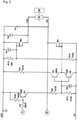
- the holding brake B of the motor M is connected to the terminals +Vb, -Vb of the circuit arrangement. Holding brake B releases the shaft of motor M as long as sufficient voltage is applied across these terminals.
- a central controller S which is remote from the motor M and the holding brake B, is shown schematically, which can switch on the supply voltage UB in order to release the brake B and switch it off in order to let the brake B apply.
- the switching element M4 is switched on permanently as soon as the operating voltage UB is present.
- the switching element M1 on the other hand, is clocked after the brake is released in order to generate the desired reduced holding voltage. Since such switching elements M1 as n-channel MOSFETs are cheaper than those with p-channel (n-channel enables faster switching with the same on-resistance), the entire circuit arrangement is related to the higher, positive potential of 24V and not, as is usually the case, to the potential 0V.
- switching element Q1 serves as a level shifter, which transmits switching pulses v4 of comparator U1, which are related to 24V, to switching elements Q3, Q4, which are related to 0V.
- the switching element Q1 must therefore be supplied with voltage pulses, based on which ultimately the switching element M1 in front of the holding brake B is opened and closed in such a way that the required voltage is present at the holding brake B at all times.
- this voltage For a certain time after switching on the operating voltage UB, this voltage must be fully applied to the holding brake B until it has released safely. A time interval of about one second has proven useful for this. Then the voltage across the holding brake B should be set to the lower holding voltage, which can correspond to about half the operating voltage UB.
- the switching element M1 For this purpose, the switching element M1 must be operated in a pulsed manner with a duty cycle of, for example, 50%. Such a pulse pattern must therefore be provided at the input of the switching element Q1.
- the purpose of this is the comparator U1, at one input of which a reference voltage v2 is present.
- This reference voltage is derived from the upper potential +24V of the operating voltage UB via a Zener diode D6 and a resistor R15. Thanks to the zener diode D6, this reference voltage v2 is independent of any voltage drops on the supply line of the operating voltage UB. This means that even a slight drop in the operating voltage UB at the input of the circuit arrangement does not lead to a reduced reference voltage v2.
- a voltage v3 picked up by the holding brake B is present at the second input of the comparator U1. Since the circuit arrangement is related to the upper potential 24V, this voltage v3 is tapped from the negative terminal -Vb and adjusted via a voltage divider made up of resistors R4 and R12 to match the reference voltage v2. A square-wave signal is picked off directly at the -Vb terminal, but this is converted into a triangular voltage at the input of the comparator U1 by means of a smoothing capacitor C1.
- the comparator U1 If the voltage v3 tapped and smoothed at the holding brake B now falls below the reference voltage v2, the comparator U1 outputs a voltage v4, which blocks the switching element Q1. The switching element M1 is then blocked via the complementary driver Q3, Q4, and the voltage across the holding brake B increases. The output signal v4 of the comparator U1 is also fed back to the reference voltage v2 via the resistor R2. As a result, the threshold at which the comparator U1 at switching off again as the voltage v3 rises, is shifted slightly upwards, so that a switching hysteresis occurs. The amount of this hysteresis and thus the switching frequency of the comparator U1 can be influenced by the choice of R2.
- a starting capacitor C8 ensures that there is no pulsed operation of the switching element M1 for a short period of time after the operating voltage UB has been applied . This is because immediately after the operating voltage is applied, v3 is still lower than v2.
- the comparator U1 thus switches through and the holding brake B is supplied with the full operating voltage UB via the switching element M1.
- the potential tapped off at the holding brake B at -Vb also increases.
- a current then flows in the direction of the starting capacitor C8, which charges it. Until this charging is completed after about one second, v3 remains below the reference voltage v2 - so there is no pulsed operation, the switching element M1 remains permanently closed, the holding brake B is charged with the full operating voltage UB and is thus opened as quickly as possible.
- the switching element M4 is always conductive as soon as the operating voltage UB is present.
- the upper terminal +Vb of the holding brake B is connected to the upper potential 24V via this switching element M4.
- the pulsed operation is enforced with the switching element M1, which connects the lower terminal -Vb of the holding brake B to the lower potential 0V. Freewheeling after each shutdown of M1 takes place via the freewheeling diode D1.
- the holding brake B After switching off the operating voltage UB, the holding brake B should apply as quickly as possible, within a few milliseconds. Because of the very high inductance of the coil of the electromagnet in the holding brake B, it is advantageous to actively switch off the freewheeling path. This is achieved via the switching element M4, which is only conductive when the operating voltage UB is present and which therefore switches off when the operating voltage UB is lost. The energy stored in the holding brake B is then thermally dissipated in the suppressor diode D4, which is connected in parallel with the switching element M4. This switching element can therefore also be referred to as a freewheeling switching element M4.
- a discharge diode D2 is also used. This discharges the capacitances C1 and above all C8, so that when the parking brake B is released again a short time later, the full functionality of the circuit arrangement is available again.
- the time required for charging the starting capacitor C8 after the operating voltage UB has been switched on, as described above, is decisive for this. A residual charge of the starting capacitor C8 could shorten this time and thus the time during which the full operating voltage UB is still applied to the holding brake B.
- varistor R21 increases the dielectric strength against interference pulses. Together with the capacitor C4, it stabilizes the input voltage.
- a capacitance that is as high as possible would be desirable for C4 because of the clocked operation of the circuit arrangement, but electrolytic capacitors can be used because of their low temperature resistance not be used at this point - close to the engine. Instead, a ceramic capacitor is used.
Landscapes
- Engineering & Computer Science (AREA)
- Mechanical Engineering (AREA)
- Transportation (AREA)
- General Engineering & Computer Science (AREA)
- Power Engineering (AREA)
- Physics & Mathematics (AREA)
- Fluid Mechanics (AREA)
- Electromagnetism (AREA)
- Stopping Of Electric Motors (AREA)
- Braking Systems And Boosters (AREA)
- Braking Arrangements (AREA)
Description
- Die vorliegende Erfindung betrifft eine Schaltungsanordnung zur Versorgung einer elektromagnetischen Haltebremse eines Elektromotors mit einer Betriebsspannung zum Lösen der Haltebremse, sowie einer gegenüber der Betriebsspannung reduzierten Spannung zum Halten der geöffneten Haltebremse.
- Elektromagnetische Haltebremsen dienen dazu, die Welle eines Motors zu halten, solange dieser außer Betrieb gesetzt ist und sich nicht bewegen darf, auch unter einem von außen zugeführten Drehmoment. Der sichere Zustand einer solchen Haltebremse ist der Zustand, in dem die Haltebremse eingefallen ist und die Welle festgehalten ist. Elektromagnetische Haltebremsen sind daher so ausgelegt, dass sie mittels eines Elektromagneten gelöst werden, an den eine Betriebsspannung angelegt wird, um die Bremsbacken zu lüften. Schaltet man diese Betriebsspannung ab, oder fällt die Betriebsspannung aus anderen Gründen aus, so werden die Bremsbacken durch mechanische Federn wieder gegen die Welle gedrückt.
- Elektromagnetische Haltebremsen finden auch im Zusammenhang mit Linearmotoren Anwendung. Dort fixieren sie im stromlosen Zustand den Läufer am Stator.
- Es ist aus der
US 3614565 bekannt, zum Lösen einer Haltebremse eine höhere Betriebsspannung zu verwenden als zum Halten der Bremse im geöffneten Zustand. Dadurch kann die Bremse einerseits schneller geöffnet werden, andererseits wird die im Elektromagnet entstehende Wärme während dem Betrieb des Motors deutlich reduziert. - In der
EP 2503682 B1 ist eine Schaltungsanordnung beschrieben, bei der die unterschiedlichen Spannungen zum Öffnen der Bremse bzw. Halten der bereits geöffneten Bremse mittels einer Pulsweitenmodulation eingestellt werden. Die Spannung am Elektromagnet der Haltebremse entspricht dabei dem zeitlichen Mittelwert der anliegenden Spannungspulse. In dieser Schrift ist offenbart, dass es in der dezentralen Antriebstechnik vorteilhaft ist, wenn der Antriebsregler und die Schaltungsanordnung zur Ansteuerung der Haltebremse unmittelbar im oder am Motor angeordnet sind. In dieser Konfiguration kann der Antriebsregler die Signale zur pulsweitenmodulierten Versorgung der Haltebremse vor Ort erzeugen. In manchen Bereichen der Technik ist aber eher eine zentrale Antriebsregelung gefordert, etwa mittels einer Numerischen Steuerung an einer mehrachsigen Werkzeugmaschine. Gemäß derEP 2503682 B1 ist dann zusätzlich zur Versorgungsleitung zum Übertragen der Bremsenspannung eine Sensorleitung nötig, die die Spannung oder den Strom direkt an der Haltebremse messen und zum zentralen Antriebsregler übertragen. Dadurch kann z.B. ein Spannungsabfall an der Versorgungsleitung erkannt und durch ein angepasstes Tastverhältnis bei der Pulsweitenmodulation ausgeglichen werden. Eine solche zusätzliche Sensorleitung bedeutet jedoch einen erhöhten Aufwand bei der Verkabelung einer Antriebslösung, und auch eine zusätzliche Fehlerquelle. - Die
DE 102007062779 A1 offenbart eine Schaltungsanordnung zur Versorgung einer elektromagnetischen Haltebremse eines Elektromotors mit einer Betriebsspannung zum Lösen der Haltebremse, sowie mit einer gegenüber der Betriebsspannung reduzierten Haltespannung zum Halten der geöffneten Haltebremse, wobei die Betriebsspannung von einer übergeordneten, von Motor und Haltebremse getrennt angeordneten Steuerung zugeführt ist. Die Schaltungsanordnung ist in oder am Motor angeordnet und enthält einen Spannungsregler, der die reduzierte Spannung nach dem Lösen der Haltebremse unabhängig von der Betriebsspannung auf einen festen Wert regelt. - Die
EP 1445852 A2 offenbart ein Verfahren und eine Vorrichtung zur aktiven Leistungsfaktorkorrektur. Zur Erzeugung von pulsweitenmodulierten Signalen kommen ein Komparator sowie ein Schaltglied zum Einsatz, wobei das Schaltglied abhängig vom Eingang des Komparators geschaltet wird. - Die
US 2008/116828 A1 offenbart eine Schaltungsanordnung zur Versorgung einer elektromagnetischen Haltebremse eines Elektromotors, die einen Komparator umfasst, der eine Referenzspannung mit einer an der Haltebremse abgegriffenen und über einen Spannungsteiler zur Verfügung gestellten Spannung vergleicht, und eingerichtet ist, an seinem Ausgang ein pulsweitenmoduliertes Signal zu erzeugen, mit dem ein Schaltelement steuerbar ist, über das die Haltebremse getaktet mit der Betriebsspannung beaufschlagt ist, wodurch sich im Mittel die Haltespannung einstellt. - Es ist Aufgabe der vorliegenden Erfindung, eine dezentral angeordnete Schaltungsanordnung zur Versorgung einer elektromagnetischen Haltebremse eines Elektromotors mit einer Betriebsspannung zum Lösen der Haltebremse, sowie einer gegenüber der Betriebsspannung reduzierten Spannung zum Halten der geöffneten Haltebremse anzugeben, die von einer zentralen Steuerung aus lediglich mit der zum Öffnen der Haltebremse notwendigen Betriebsspannung versorgt werden muss.
- Diese Aufgabe wird gelöst durch eine Schaltungsanordnung gemäß Anspruch 1. Vorteilhafte Details dieser Schaltungsanordnung ergeben sich auch aus den von Anspruch 1 abhängigen Ansprüchen.
- Es wird eine Schaltungsanordnung zur Versorgung einer elektromagnetischen Haltebremse eines Elektromotors mit einer Betriebsspannung zum Lösen der Haltebremse, sowie einer gegenüber der Betriebsspannung reduzierten Spannung zum Halten der geöffneten Haltebremse offenbart.
- Motor und Haltebremse bilden hierbei eine Einheit, und die erfindungsgemäße Schaltungsanordnung ist an oder in dieser Einheit angeordnet. Die Betriebsspannung zum Betätigen der Haltebremse wird von außen, von einer separat und entfernt angeordneten, übergeordneten oder zentralen Steuerung zugeführt. Eine einzelne zentrale Steuerung kann dabei mehrere Motoren und deren Haltebremsen ansteuern, etwa an einer Werkzeugmaschine.
- Die am oder im Motor bzw. an oder in der Haltebremse angeordnete Schaltungsanordnung muss von einer zentralen Steuerung lediglich mit einer Betriebsspannung beaufschlagt werden, wenn die Haltebremse gelöst werden soll. Wird diese Betriebsspannung wieder abgeschaltet, so fällt die Haltbremse erneut ein. Die zentrale Steuerung muss weder eine pulsweitenmodulierte Betriebsspannung erzeugen, noch muss der Steuerung in irgendeiner Form der Spannungsabfall auf der Versorgungsleitung für Betriebsspannung der Haltebremse mitgeteilt werden. Diese Nachteile des oben genannten Standes der Technik sind gemäß der Erfindung für die zentrale Antriebsregelung überwunden.
- Die erfindungsgemäße Schaltungsanordnung sorgt dezentral dafür, dass die Haltebremse schnell (das heißt mit voller Betriebsspannung) gelöst wird, und dass die Bremse im weiteren Verlauf mit einer reduzierten Spannung (Haltespannung) offen gehalten wird, die nicht vom Spannungsabfall auf der Versorgungsleitung der Haltebremse abhängt, um so den Energieverbrauch deutlich zu reduzieren. Außerdem sorgt die Schaltungsanordnung für ein schnelles Einfallen der Haltebremse nach dem Abschalten der Betriebsspannung.
- Die dezentral im oder am Motor (bzw. dessen Gehäuse) und damit in unmittelbarer Nähe zur Haltebremse angeordnete Schaltungsanordnung ist dank eines integrierten, als Hysteresewandler eingesetzten Komparators so autark ausgelegt, dass von der zentralen Steuerung lediglich die zum Lüften der Bremse notwendige Betriebsspannung für die Haltebremse zur Verfügung gestellt werden muss. Die Schaltungsanordnung sorgt dann selbsttätig dafür, dass zunächst die volle Betriebsspannung an den Elektromagnet der Haltebremse angelegt und damit die Bremse schnell gelüftet wird. Danach wird durch die Schaltungsanordnung eine mittels Pulsweitenmodulation reduzierte Spannung zum Halten der Bremse im gelüfteten Zustand erzeugt, indem die Betriebsspannung gepulst mit einem passenden Tastverhältnis angelegt wird, so dass die mittlere Spannung über der Haltebremse gerade der Haltespannung entspricht.
- Da eine Spannungsregelung erfolgt, können an die Schaltungsanordnung Haltebremsen unterschiedlichen Typs, also insbesondere solche mit unterschiedlicher Stromaufnahme angeschlossen werden.
- Der zeitliche Ablauf beim Lösen der Haltebremse, also insbesondere die Dauer der ersten Phase, während der die Haltebremse mit voller Betriebsspannung gelüftet wird, bevor auf Haltespannung umgeschaltet wird, ist durch die Auslegung der einzelnen Bauelemente der Schaltungsanordnung vorgegeben und benötigt keinerlei Eingriff durch eine übergeordnete Steuerung, der zeitliche Ablauf ist sozusagen bereits in der Schaltungsanordnung festgelegt.
- Weitere Vorteile und Einzelheiten der vorliegenden Erfindung ergeben sich aus der nachfolgenden Beschreibung eines Ausführungsbeispiels anhand der Figuren.
- Dabei zeigt
- Figur 1
- einen ersten Teil der Schaltungsanordnung,
- Figur 2
- einen zweiten Teil der Schaltungsanordnung.
- Die
Figuren 1 und2 ergeben in der Zusammenschau das vollständige Schaltbild einer erfindungsgemäßen Schaltungsanordnung gemäß einem ersten Ausführungsbeispiel. Einem Fachmann auf dem Gebiet der Antriebstechnik, insbesondere für elektronische Schaltungen zur Ansteuerung von Komponenten der Antriebstechnik, bietet schon dieses Schaltbild eine umfassende Offenbarung der vorliegenden Erfindung. Im Folgenden werden viele dieser Details im Text erklärt, doch sei ein späterer Rückgriff auf weitere Details der in den Figuren offenbarten Schaltungsanordnung ausdrücklich vorbehalten. - Die Haltebremse B des Motors M ist mit den Klemmen +Vb, -Vb der Schaltungsanordnung verbunden. Die Haltebremse B gibt die Welle des Motors M frei, solange ausreichend Spannung über diese Klemmen angelegt wird.
- Wird also von außen eine Betriebsspannung UB an die Klemmen 0V, 24V der Schaltungsanordnung angelegt, so ist die Haltebremse B über die Schaltelemente M1 und M4 mit dieser Betriebsspannung verbunden. In der
Figur 1 ist schematisch eine zentrale, vom Motor M und der Haltebremse B entfernt angeordnete Steuerung S dargestellt, die die Versorgungsspannung UB einschalten kann, um die Bremse B zu lösen, und ausschalten kann, um die Bremse B einfallen zu lassen. - Das Schaltelement M4 ist dauerhaft eingeschaltet, sobald die Betriebsspannung UB anliegt. Das Schaltelement M1 wird hingegen nach dem Öffnen der Bremse getaktet, um so die gewünschte reduzierte Haltespannung zu erzeugen. Da solche Schaltelemente M1 als n-Kanal MOSFETs günstiger sind als solche mit p-Kanal (n-Kanal ermöglicht schnelleres Schalten bei gleichem On-Widerstand), ist die gesamte Schaltungsanordnung auf das höhere, positive Potential 24V bezogen, und nicht wie sonst üblich auf das Potential 0V.
- Zur Ansteuerung des Schaltelements M1 dient ein aus den Schaltelementen Q3 und Q4 zusammengesetzter Komplementärtreiber, der wiederum vom Schaltelement Q1 angesteuert wird. Dabei dient Schaltelement Q1 als Level-Shifter, der die auf 24V bezogenen Schaltpulse v4 des Komparators U1 auf die Schaltelemente Q3, Q4 überträgt, die auf 0V bezogen sind. Das Schaltelement Q1 muss daher mit Spannungspulsen versorgt werden, anhand derer letztlich das Schaltelement M1 vor der Haltebremse B so geöffnet und geschlossen wird, dass jederzeit die benötigte Spannung an der Haltebremse B anliegt.
- So muss für eine gewisse Zeit nach dem Einschalten der Betriebsspannung UB diese Spannung voll an der Haltebremse B anliegen, bis diese sicher geöffnet hat. Ein Zeitintervall von etwa einer Sekunde hat sich dafür bewährt. Danach soll die Spannung über der Haltebremse B auf die niedrigere Haltespannung eingestellt werden, die etwa der halben Betriebsspannung UB entsprechen kann. Hierzu muss das Schaltelement M1 mit einem Tastverhältnis von beispielsweise 50% gepulst betrieben werden. So ein Pulsmuster muss also am Eingang des Schaltelements Q1 bereit gestellt werden.
- Hierzu dient der Komparator U1, an dessen einen Eingang eine Referenzspannung v2 anliegt. Diese Referenzspannung wird über eine Zenerdiode D6 und einen Widerstand R15 vom oberen Potential +24V der Betriebsspannung UB abgeleitet. Dank der Zenerdiode D6 ist diese Referenzspannung v2 unabhängig von eventuellen Spannungsabfällen auf der Zuleitung der Betriebsspannung UB. Das bedeutet, dass auch ein leichtes Absinken der Betriebsspannung UB am Eingang der Schaltungsanordnung nicht zu einer reduzierten Referenzspannung v2 führt.
- Am zweiten Eingang des Komparators U1 liegt eine von der Haltebremse B abgegriffene Spannung v3. Da die Schaltungsanordnung auf das obere Potential 24V bezogen ist, wird diese Spannung v3 vom negativen Anschluss -Vb abgegriffen und über einen Spannungsteiler aus den Widerständen R4 und R12 passend zur Referenzspannung v2 eingestellt. Unmittelbar an der Klemme -Vb wird ein Rechtecksignal abgegriffen, das jedoch am Eingang des Komparators U1 mittels eines Glättungskondensators C1 in eine Dreieckspannung umgewandelt wird.
- Fällt nun die an der Haltebremse B abgegriffene und geglättete Spannung v3 unter die Referenzspannung v2, so gibt der Komparator U1 eine Spannung v4 ab, die das Schaltelement Q1 sperrt. Über den Komplementärtreiber Q3, Q4 wird dann das Schaltelement M1 gesperrt, die Spannung über der Haltebremse B steigt an. Das Ausgangssignal v4 des Komparators U1 wird außerdem über den Widerstand R2 auf die Referenzspannung v2 rückgekoppelt. Dadurch wird die Schwelle, bei der der Komparator U1 bei steigender Spannung v3 wieder abschaltet, etwas nach oben verschoben, so dass eine Schalthysterese entsteht. Durch die Wahl von R2 kann der Betrag dieser Hysterese und damit die Schaltfrequenz des Komparators U1 beeinflusst werden. Bewährt haben sich hier Schaltfrequenzen im Bereich von 1 - 10 kHz. Durch den auf diese Weise gepulsten Betrieb des Schaltelements M1, und dank der Unabhängigkeit der Referenzspannung v2 von Leitungsverlusten bei der Zuführung der Betriebsspannung UB, kann an der Haltebremse B eine Haltespannung sehr definiert und nahe am günstigsten Punkt eingestellt werden, bei dem die Haltebremse noch sicher geöffnet bleibt, bei dem aber keine unnötige Verlustleistung im Elektromagnet der Bremse B umgesetzt wird. Außerdem fällt die Bremse B auch schneller wieder ein, wenn die Abschaltung der Betriebsspannung von der niedrigeren Haltespannung aus erfolgt.
- Da die Schaltungsanordnung aber auch dafür sorgen muss, dass zum Öffnen der Haltebremse B zunächst die volle Betriebsspannung UB an der Haltebremse B anliegt, sorgt ein Startkondensator C8 dafür, dass während einer kurzen Zeitspanne nach dem Anlegen der Betriebsspannung UB noch kein Pulsbetrieb des Schaltelements M1 stattfindet. Unmittelbar nach dem Anlegen der Betriebsspannung ist nämlich v3 noch niedriger als v2. Damit Schaltet der Komparator U1 durch, und über Schaltelement M1 wird die Haltebremse B mit der vollen Betriebsspannung UB versorgt. Damit steigt auch das an der Haltebremse B bei -Vb abgegriffene Potential an. Es fließt dann ein Strom in Richtung Startkondensator C8, der diesen auflädt. Bis diese Aufladung nach ca. einer Sekunde abgeschlossen ist, bleibt v3 unterhalb der Referenzspannung v2 - es findet also noch kein Pulsbetrieb statt, das Schaltelement M1 bleibt dauerhaft geschlossen, die Haltebremse B wird mit voller Betriebsspannung UB beaufschlagt und damit schnellst möglich geöffnet.
- Erst wenn der Startkondensator C8 nach dieser ersten Sekunde vollständig geladen ist, steigt v3 über v2 hinaus an, und der oben beschriebene Pulsbetrieb setzt ein. Die Spannung über der Haltebremse B wird nun auf die Haltespannung reduziert.
- Wie erwähnt ist das Schaltelement M4 stets leitend, sobald die Betriebsspannung UB anliegt. Über dieses Schaltelement M4 ist die obere Klemme +Vb der Haltebremse B mit dem oberen Potential 24V verbunden. Der Pulsbetrieb wird mit dem Schaltelement M1 erzwungen, das die untere Klemme -Vb der Haltebremse B mit dem unteren Potential 0V verbindet. Der Freilauf nach jeder Abschaltung von M1 erfolgt über die Freilaufdiode D1.
- Nach dem Abschalten der Betriebsspannung UB soll die Haltebremse B möglichst schnell, innerhalb weniger Millisekunden einfallen. Wegen der recht hohen Induktivität der Spule des Elektromagneten in der Haltebremse B ist es hierzu vorteilhaft, den Freilaufpfad aktiv abzuschalten. Dies wird über das Schaltelement M4 erreicht, das ja nur bei anliegender Betriebsspannung UB leitend ist, und das daher bei Wegfall der Betriebsspannung UB abschaltet. Die in der Haltebremse B gespeicherte Energie wird dann thermisch in der Suppressordiode D4 vernichtet, die parallel zum Schaltelement M4 geschaltet ist. Dieses Schaltelement kann also auch als Freilaufschaltelement M4 bezeichnet werden.
- Beim Abschalten der Haltebremse B durch das Abschalten der Betriebsspannung UB kommt außerdem eine Entladediode D2 zum Einsatz. Diese entlädt die Kapazitäten C1 und vor allem C8, damit bei einem erneuten Lösen der Haltbremse B kurze Zeit später die volle Funktionalität der Schaltungsanordnung wieder zur Verfügung steht. Hierfür ist der Zeitbedarf für die Aufladung des Startkondensators C8 nach dem Einschalten der Betriebsspannung UB wie oben beschrieben entscheidend. Eine Restladung des Startkondensators C8 könnte diese Zeit verkürzen, und damit die Zeit, während der noch die volle Betriebsspannung UB an der Haltebremse B anliegt.
- Am Eingang der Schaltungsanordnung erhöht Varistor R21 die Spannungsfestigkeit gegenüber Störimpulsen. Zusammen mit dem Kondensator C4 stabilisiert er die Eingangsspannung. Eine möglichst hohe Kapazität wäre für C4 wegen des getakteten Betriebs der Schaltungsanordnung wünschenswert, allerdings können Elektrolytkondensatoren wegen deren zu geringen Temperaturfestigkeit an dieser Stelle - nahe am Motor - nicht eingesetzt werden. Stattdessen kommt ein Keramikkondensator zum Einsatz.
- Als weitere Maßnahme, die Schaltungsanordnung möglichst robust zu gestalten, wurde darauf geachtet, dass keine niederohmigen Verbindungen von 24V zu 0V den Komparator U1 beeinflussen. R23 und R16 blocken hohe Ströme bei schnell ansteigender Versorgungsspannung ab.
Claims (8)
- Schaltungsanordnung zur Versorgung einer elektromagnetischen Haltebremse (B) eines Elektromotors (M) mit einer Betriebsspannung (UB) zum Lösen der Haltebremse (B), sowie einer gegenüber der Betriebsspannung reduzierten Haltespannung zum Halten der geöffneten Haltebremse (B), wobei die Schaltungsanordnung einen Spannungsregler enthält, der eingerichtet ist, die reduzierte Spannung nach dem Lösen der Haltebremse (B) unabhängig von der Betriebsspannung (UB) auf einen festen Wert zu regeln, wobei die Schaltungsanordnung einen Komparator (U1) umfasst, der eine Referenzspannung (v2) mit einer an der Haltebremse (B) abgegriffenen und über einen Spannungsteiler (R4, R12) zur Verfügung gestellten Spannung (v3) vergleicht, und der eingerichtet ist, an seinem Ausgang ein pulsweitenmoduliertes Signal (v4) zu erzeugen, mit dem ein Schaltelement (M1) steuerbar ist, über das die Haltebremse (B) getaktet mit der Betriebsspannung (UB) beaufschlagt ist, wodurch sich im Mittel die Haltespannung einstellt, dadurch gekennzeichnet, dass der Komparator (U1) am Eingang für die abgegriffene Spannung (v3) so mit einem Startkondensator (C8) verbunden ist, dass erst dann ein pulsweitenmoduliertes Signal (v4) am Ausgang des Komparators (U1) abgegeben wird, wenn dieser Startkondensator (C8) ausreichend geladen ist, und dass dadurch zunächst nach dem Anlegen der Betriebsspannung (UB) an die Schaltungsanordnung die Haltebremse (B) mit der vollen Betriebsspannung (UB) beaufschlagt ist, wobei der Startkondensator (C8) so dimensioniert ist, dass die Zeit bis zu dessen ausreichender Aufladung zum Lösen der Haltebremse (B) ausreicht, und wobei die Betriebsspannung (UB) von einer übergeordneten, von Motor (M) und Haltebremse (B) getrennt angeordneten Steuerung (S) zugeführt ist, und wobei die Schaltungsanordnung in oder am Motor (M) oder in oder an der Haltebremse (B) angeordnet ist.
- Schaltungsanordnung nach Anspruch 1, dadurch gekennzeichnet, dass die an der Haltebremse (B) abgegriffene Spannung (v3) mittels eines Glättungskondensators (C1) zu einer Dreieckspannung geformt ist.
- Schaltungsanordnung nach Anspruch 1 oder 2, dadurch gekennzeichnet, dass der Ausgang des Komparators (U1) auf die Referenzspannung (V2) rückgekoppelt ist.
- Schaltungsanordnung nach einem der vorhergehenden Ansprüche, dadurch gekennzeichnet, dass die Referenzspannung (v2) mittels einer Zenerdiode (D6) von der Betriebsspannung (UB) abgeleitet ist
- Schaltungsanordnung nach einem der vorhergehenden Ansprüche, dadurch gekennzeichnet, dass eine Entladediode (D2) den Startkondensator (C8) entlädt, falls keine Betriebsspannung (UB) an der Schaltungsanordnung anliegt.
- Schaltungsanordnung nach einem der vorhergehenden Ansprüche, dadurch gekennzeichnet, dass die Schaltungsanordnung das höhere Potential (24V) der Betriebsspannung (UB) als Bezugspotential verwendet, und dass das Schaltelement (M1) als n-Kanal MOSFET ausgebildet ist, der einen negativen Anschluss der Haltebremse (B) mit dem unteren Potential (0V) der Betriebsspannung (UB) verbindet.
- Schaltungsanordnung nach einem der vorhergehenden Ansprüche, dadurch gekennzeichnet, dass ein Freilaufschaltelement (M4) einen Freilaufstrom durch die Haltebremse (B) sperrt, wenn keine Betriebsspannung (UB) an der Schaltungsanordnung anliegt.
- Schaltungsanordnung nach Anspruch 7, dadurch gekennzeichnet, dass eine Suppressordiode (D4) parallel zum Freilaufschaltelement (M4) geschaltet ist.
Applications Claiming Priority (1)
| Application Number | Priority Date | Filing Date | Title |
|---|---|---|---|
| DE102015216496.9A DE102015216496A1 (de) | 2015-08-28 | 2015-08-28 | Schaltungsanordnung |
Publications (2)
| Publication Number | Publication Date |
|---|---|
| EP3142247A1 EP3142247A1 (de) | 2017-03-15 |
| EP3142247B1 true EP3142247B1 (de) | 2022-03-23 |
Family
ID=56096535
Family Applications (1)
| Application Number | Title | Priority Date | Filing Date |
|---|---|---|---|
| EP16172174.1A Active EP3142247B1 (de) | 2015-08-28 | 2016-05-31 | Schaltungsanordnung |
Country Status (8)
| Country | Link |
|---|---|
| US (1) | US9847741B2 (de) |
| EP (1) | EP3142247B1 (de) |
| JP (1) | JP6681301B2 (de) |
| KR (1) | KR102520791B1 (de) |
| CN (1) | CN106487282B (de) |
| DE (1) | DE102015216496A1 (de) |
| ES (1) | ES2910663T3 (de) |
| TW (1) | TWI717359B (de) |
Families Citing this family (6)
| Publication number | Priority date | Publication date | Assignee | Title |
|---|---|---|---|---|
| FI123506B (fi) * | 2012-05-31 | 2013-06-14 | Kone Corp | Hissin käyttölaite sekä hissin turvajärjestely |
| ES2980266T3 (es) * | 2018-12-20 | 2024-09-30 | Inventio Ag | Procedimiento y control de freno para controlar un freno de una instalación de ascensor |
| US11060700B2 (en) * | 2019-09-30 | 2021-07-13 | Guangzhou Haoyang Electronic Co., Ltd. | Motor braking system of stage light |
| CN111425540B (zh) * | 2020-03-06 | 2024-12-03 | 奥创动力传动(深圳)有限公司 | 一种电磁制动器控制装置 |
| CN112276939B (zh) | 2020-09-16 | 2022-02-11 | 珠海格力电器股份有限公司 | 一种机器人的控制装置、方法和机器人 |
| US12071119B2 (en) * | 2021-02-24 | 2024-08-27 | Textron Innovations Inc. | Emergency vehicle braking using closed-loop pulsing |
Citations (1)
| Publication number | Priority date | Publication date | Assignee | Title |
|---|---|---|---|---|
| US20080116828A1 (en) * | 2006-11-21 | 2008-05-22 | Fanuc Ltd | Motor driving apparatus for driving and braking brake-equipped motor |
Family Cites Families (37)
| Publication number | Priority date | Publication date | Assignee | Title |
|---|---|---|---|---|
| US3779612A (en) * | 1970-05-19 | 1973-12-18 | Beka St Aubin Sa | Trailer brake control system |
| JPS5023739B1 (de) * | 1970-06-16 | 1975-08-09 | ||
| US3614565A (en) | 1970-07-09 | 1971-10-19 | Harnischfeger Corp | Control for electromechanical brake |
| US3811526A (en) * | 1972-07-20 | 1974-05-21 | C Adahan | Rate of change of velocity control system |
| US3842329A (en) * | 1973-11-12 | 1974-10-15 | Harnischfeger Corp | Control for electromechanical brake having transistorized timing reset means |
| US3917029A (en) * | 1974-05-10 | 1975-11-04 | Armor Elevator Co Inc | Transportation system with brake control and combined brake and field power supply |
| US4232910A (en) * | 1976-04-12 | 1980-11-11 | Motor Wheel Corporation | Systems and methods for controlling trailer brakes as a function of trailer wheel rotation |
| GB1539210A (en) * | 1976-09-14 | 1979-01-31 | Girling Ltd | Anti-skid system |
| DE2715870B2 (de) * | 1977-04-09 | 1981-07-16 | Carl Schenck Ag, 6100 Darmstadt | Verfahren zur schnellen Veränderung des Bremsmomentes einer Wirbelstrombremse und Vorrichtung zur Durchführung des Verfahrens |
| US4196936A (en) * | 1978-02-13 | 1980-04-08 | Motor Wheel Corporation | Trailer brake control system |
| US4398252A (en) * | 1981-04-20 | 1983-08-09 | Kelsey-Hayes Co. | Electric controller having output power limiting circuit |
| US4460991A (en) * | 1981-05-28 | 1984-07-17 | Nippon Gakki Kabushiki Kaisha | Pickup device for disc player |
| IT1156372B (it) * | 1982-06-22 | 1987-02-04 | Fiat Auto Spa | Dispositivo di regolazione automatica della frequenza di attivazione di un tergicristallo per veicoli |
| US4787205A (en) * | 1985-02-14 | 1988-11-29 | Fontaine William G | Vehicle brake system |
| US4841276A (en) * | 1985-06-17 | 1989-06-20 | Roy P. Abel | Vehicle low speed warning system |
| US4733152A (en) * | 1986-03-10 | 1988-03-22 | Isco, Inc. | Feedback system |
| JPS62244109A (ja) * | 1986-04-16 | 1987-10-24 | Toshiba Corp | 電磁石装置のコイル駆動回路 |
| US5278483A (en) * | 1986-04-19 | 1994-01-11 | Sew-Eurodrive Gmbh & Co. | Motor brake with single free wheeling diode connected in parallel with only one partial coil of brake magnet coil |
| US4712841A (en) * | 1986-11-19 | 1987-12-15 | Allied Corporation | Fail safe circuit for an anti-lock braking system modulator drive |
| US5217280A (en) * | 1989-07-06 | 1993-06-08 | Nartron Corporation | Pressure sensitive signal device for vehicle brake pedal |
| US5352028A (en) * | 1989-08-07 | 1994-10-04 | Tekonsha Engineering Company | Controller for electric braking systems |
| US5050937A (en) * | 1989-08-07 | 1991-09-24 | Tekonsha Engineering Company | Controller for electric braking systems |
| US5149176A (en) * | 1989-08-07 | 1992-09-22 | Tekonsha Engineering Company | Controller for electric braking systems |
| FR2655005B1 (fr) * | 1989-11-27 | 1994-04-08 | Andruet Jean Claude | Dispositif de commande du frein de parc pour un vehicule automobile. |
| US5091680A (en) * | 1990-02-06 | 1992-02-25 | Seagate Technology, Inc. | Motor brake circuit for magnetic disk drive system |
| TW301081B (de) * | 1995-08-02 | 1997-03-21 | Hitachi Ltd | |
| EP1008232B1 (de) * | 1997-08-25 | 2003-11-05 | Sew-Eurodrive GmbH & Co. KG | Verfahren und schaltungsanordnung zum betrieb einer elektromagnetisch betätigbaren, mechanischen bremse eines elektromotors |
| DE19920307A1 (de) * | 1999-05-03 | 2000-11-16 | St Microelectronics Gmbh | Elektrische Schaltung zum Steuern einer Last |
| JP4364554B2 (ja) * | 2002-06-07 | 2009-11-18 | 株式会社ルネサステクノロジ | スイッチング電源装置及びスイッチング電源システム |
| EP1445852B1 (de) * | 2003-02-07 | 2012-09-26 | Baumüller Nürnberg Gmbh | Verfahren und Vorrichtung zur aktiven Leistungsfaktorkorrektur |
| JP3856767B2 (ja) * | 2003-05-07 | 2006-12-13 | 多摩川精機株式会社 | ブレーキ付きモータ |
| CN2741948Y (zh) * | 2004-05-24 | 2005-11-23 | 孔凡华 | 交流起重机调速的控制装置 |
| EP1657815A1 (de) | 2004-11-12 | 2006-05-17 | Dialog Semiconductor GmbH | Technik zur Frequenzstabilisierung für einen selbst oszillierenden Modulator |
| JP4811952B2 (ja) * | 2006-12-28 | 2011-11-09 | 株式会社ハーモニック・ドライブ・システムズ | 無励磁作動型電磁ブレーキ |
| EP2503682B1 (de) | 2011-03-22 | 2013-09-25 | Siemens Aktiengesellschaft | Schaltungsanordnung |
| JP2014200161A (ja) * | 2013-03-13 | 2014-10-23 | パナソニック株式会社 | 制御装置の電源回路 |
| JP5911639B2 (ja) * | 2013-04-25 | 2016-04-27 | 三菱電機株式会社 | ブレーキ付モータ |
-
2015
- 2015-08-28 DE DE102015216496.9A patent/DE102015216496A1/de not_active Withdrawn
-
2016
- 2016-05-31 ES ES16172174T patent/ES2910663T3/es active Active
- 2016-05-31 EP EP16172174.1A patent/EP3142247B1/de active Active
- 2016-06-16 TW TW105118987A patent/TWI717359B/zh active
- 2016-07-12 KR KR1020160087911A patent/KR102520791B1/ko active Active
- 2016-08-11 US US15/233,958 patent/US9847741B2/en active Active
- 2016-08-26 CN CN201610729553.XA patent/CN106487282B/zh active Active
- 2016-08-26 JP JP2016165616A patent/JP6681301B2/ja active Active
Patent Citations (1)
| Publication number | Priority date | Publication date | Assignee | Title |
|---|---|---|---|---|
| US20080116828A1 (en) * | 2006-11-21 | 2008-05-22 | Fanuc Ltd | Motor driving apparatus for driving and braking brake-equipped motor |
Non-Patent Citations (2)
| Title |
|---|
| BURR-BROWN: "PWM SOLENOID/VALVE DRIVER", 1 January 1998 (1998-01-01), XP055640944, Retrieved from the Internet <URL:https://www.bg-electronics.de/datenblaetter/Schaltkreise/DRV102.pdf> [retrieved on 20191111] * |
| KUMBHAR MAHESH ET AL: "Magnetostatic analysis and power optimization of electric release brake", 2014 ANNUAL INTERNATIONAL CONFERENCE ON EMERGING RESEARCH AREAS: MAGNETICS, MACHINES AND DRIVES (AICERA/ICMMD), IEEE, 24 July 2014 (2014-07-24), pages 1 - 4, XP032648199, DOI: 10.1109/AICERA.2014.6908234 * |
Also Published As
| Publication number | Publication date |
|---|---|
| DE102015216496A1 (de) | 2017-03-02 |
| KR20170026117A (ko) | 2017-03-08 |
| EP3142247A1 (de) | 2017-03-15 |
| JP6681301B2 (ja) | 2020-04-15 |
| US9847741B2 (en) | 2017-12-19 |
| ES2910663T3 (es) | 2022-05-13 |
| TW201725848A (zh) | 2017-07-16 |
| KR102520791B1 (ko) | 2023-04-12 |
| TWI717359B (zh) | 2021-02-01 |
| US20170063259A1 (en) | 2017-03-02 |
| CN106487282B (zh) | 2021-03-02 |
| CN106487282A (zh) | 2017-03-08 |
| JP2017046576A (ja) | 2017-03-02 |
Similar Documents
| Publication | Publication Date | Title |
|---|---|---|
| EP3142247B1 (de) | Schaltungsanordnung | |
| DE102007006179B4 (de) | Schaltungsanordnung und Verfahren zum Betreiben einer induktiven Last | |
| EP2828969B1 (de) | Verfahren zum betrieb eines kapazitiven stellgliedes | |
| DE19615072A1 (de) | Verfahren zum Steuern oder Regeln eines Elektromotors, und Anordnung zur Durchführung eines solchen Verfahrens | |
| EP1067668A2 (de) | Schaltungsanordnung zum Betreiben eines elektromagnetischen Stellglieds | |
| DE102013219609B4 (de) | Verfahren zum Betreiben einer Schaltungsanordnung zum Laden und Entladen eines kapazitiven Aktuators | |
| DE19518991A1 (de) | Verfahren zum Betrieb eines elektronisch kommutierten Motors, und Motor zur Durchführung eines solchen Verfahrens | |
| DE102015217311B4 (de) | Verfahren und Vorrichtung zur Steuerung eines Spulenantriebs | |
| DE102014226716A1 (de) | Spannungsverdoppler und Spannungsverdopplungsverfahren zur Verwendung im PMW-Modus | |
| EP2129897A1 (de) | Ansteuerschaltung und ansteuerverfahren für ein piezoelektrisches element | |
| DE102014116689B4 (de) | Vorrichtung und Verfahren zum Sichern einer Antriebssteuerung gegen Versorgungsspannungsausfälle | |
| DE102013224586A1 (de) | Frequenzerzeugung für einen Resonanzwandler | |
| DE102005028344A1 (de) | Verfahren und Schaltungsanordnung zur Regelung eines mehrphasigen bürstenlosen Elektromotors | |
| DE19810321A1 (de) | Verfahren und Schaltungsanordnung zur Strom- und Ladungsregelung von kapazitiven Lasten und deren Verwendung | |
| DE102014220393B4 (de) | Hydroaggregat für ein Bremssystem mit Gleichspannungswandler sowie System mit Hydroaggregat und Steuereinrichtung | |
| EP2887534B1 (de) | Elektronische Anlaufschaltung für einen Einphasen-Induktionsmotor | |
| WO2007071520A1 (de) | Verfahren und vorrichtung zur ansteuerung eines elektromotors | |
| DE112015000065T5 (de) | Spannungssteuerungsvorrichtung und Spannungssteuerungsverfahren | |
| WO2013189599A2 (de) | Stellantrieb, stellantriebanlage, verfahren zum betreiben eines stellantriebs und verfahren zum betreiben einer stellantriebanlage | |
| DE102013210641A1 (de) | Verfahren zum Einstellen einer Stromstärke zum Betreiben einer Halbleiterlichtquelle einer Beleuchtungseinrichtung | |
| DE102011112455A1 (de) | Verfahren und elektronische Schaltung zur Stromversorgung für eine gepulste Beleuchtungsquelle | |
| EP2799946B1 (de) | Verfahren zur Kompatibilitätsherstellung zwischen einem Feldgerät und einer Diagnoseeinrichtung und Interfacegerät | |
| EP1992060B1 (de) | Vorrichtung und verfahren zur gleichspannungsversorgung von elektronischen ansteuerschaltungen für elektromotoren | |
| EP0324902B1 (de) | Netzteil zur Erzeugung einer geregelten Gleichspannung | |
| EP3043461A2 (de) | Versorgungsschaltung zur versorgung eines schweissgerätes |
Legal Events
| Date | Code | Title | Description |
|---|---|---|---|
| PUAI | Public reference made under article 153(3) epc to a published international application that has entered the european phase |
Free format text: ORIGINAL CODE: 0009012 |
|
| STAA | Information on the status of an ep patent application or granted ep patent |
Free format text: STATUS: REQUEST FOR EXAMINATION WAS MADE |
|
| 17P | Request for examination filed |
Effective date: 20160531 |
|
| AK | Designated contracting states |
Kind code of ref document: A1 Designated state(s): AL AT BE BG CH CY CZ DE DK EE ES FI FR GB GR HR HU IE IS IT LI LT LU LV MC MK MT NL NO PL PT RO RS SE SI SK SM TR |
|
| AX | Request for extension of the european patent |
Extension state: BA ME |
|
| STAA | Information on the status of an ep patent application or granted ep patent |
Free format text: STATUS: EXAMINATION IS IN PROGRESS |
|
| 17Q | First examination report despatched |
Effective date: 20170321 |
|
| RBV | Designated contracting states (corrected) |
Designated state(s): AL AT BE BG CH CY CZ DE DK EE ES FI FR GB GR HR HU IE IS IT LI LT LU LV MC MK MT NL NO PL PT RO RS SE SI SK SM TR |
|
| GRAP | Despatch of communication of intention to grant a patent |
Free format text: ORIGINAL CODE: EPIDOSNIGR1 |
|
| STAA | Information on the status of an ep patent application or granted ep patent |
Free format text: STATUS: GRANT OF PATENT IS INTENDED |
|
| RIC1 | Information provided on ipc code assigned before grant |
Ipc: B60T 13/74 20060101ALN20211008BHEP Ipc: F16D 121/22 20120101ALN20211008BHEP Ipc: F16D 121/14 20120101ALI20211008BHEP Ipc: B60T 13/04 20060101ALI20211008BHEP Ipc: F16D 65/18 20060101ALI20211008BHEP Ipc: H02P 29/00 20160101ALI20211008BHEP Ipc: H02P 3/04 20060101ALI20211008BHEP Ipc: H02P 29/04 20060101AFI20211008BHEP |
|
| INTG | Intention to grant announced |
Effective date: 20211026 |
|
| GRAS | Grant fee paid |
Free format text: ORIGINAL CODE: EPIDOSNIGR3 |
|
| GRAA | (expected) grant |
Free format text: ORIGINAL CODE: 0009210 |
|
| STAA | Information on the status of an ep patent application or granted ep patent |
Free format text: STATUS: THE PATENT HAS BEEN GRANTED |
|
| AK | Designated contracting states |
Kind code of ref document: B1 Designated state(s): AL AT BE BG CH CY CZ DE DK EE ES FI FR GB GR HR HU IE IS IT LI LT LU LV MC MK MT NL NO PL PT RO RS SE SI SK SM TR |
|
| REG | Reference to a national code |
Ref country code: GB Ref legal event code: FG4D Free format text: NOT ENGLISH |
|
| REG | Reference to a national code |
Ref country code: CH Ref legal event code: EP |
|
| REG | Reference to a national code |
Ref country code: DE Ref legal event code: R096 Ref document number: 502016014664 Country of ref document: DE |
|
| REG | Reference to a national code |
Ref country code: IE Ref legal event code: FG4D Free format text: LANGUAGE OF EP DOCUMENT: GERMAN |
|
| REG | Reference to a national code |
Ref country code: AT Ref legal event code: REF Ref document number: 1478141 Country of ref document: AT Kind code of ref document: T Effective date: 20220415 |
|
| REG | Reference to a national code |
Ref country code: ES Ref legal event code: FG2A Ref document number: 2910663 Country of ref document: ES Kind code of ref document: T3 Effective date: 20220513 |
|
| REG | Reference to a national code |
Ref country code: LT Ref legal event code: MG9D |
|
| REG | Reference to a national code |
Ref country code: NL Ref legal event code: MP Effective date: 20220323 |
|
| PG25 | Lapsed in a contracting state [announced via postgrant information from national office to epo] |
Ref country code: SE Free format text: LAPSE BECAUSE OF FAILURE TO SUBMIT A TRANSLATION OF THE DESCRIPTION OR TO PAY THE FEE WITHIN THE PRESCRIBED TIME-LIMIT Effective date: 20220323 Ref country code: RS Free format text: LAPSE BECAUSE OF FAILURE TO SUBMIT A TRANSLATION OF THE DESCRIPTION OR TO PAY THE FEE WITHIN THE PRESCRIBED TIME-LIMIT Effective date: 20220323 Ref country code: NO Free format text: LAPSE BECAUSE OF FAILURE TO SUBMIT A TRANSLATION OF THE DESCRIPTION OR TO PAY THE FEE WITHIN THE PRESCRIBED TIME-LIMIT Effective date: 20220623 Ref country code: LT Free format text: LAPSE BECAUSE OF FAILURE TO SUBMIT A TRANSLATION OF THE DESCRIPTION OR TO PAY THE FEE WITHIN THE PRESCRIBED TIME-LIMIT Effective date: 20220323 Ref country code: HR Free format text: LAPSE BECAUSE OF FAILURE TO SUBMIT A TRANSLATION OF THE DESCRIPTION OR TO PAY THE FEE WITHIN THE PRESCRIBED TIME-LIMIT Effective date: 20220323 Ref country code: BG Free format text: LAPSE BECAUSE OF FAILURE TO SUBMIT A TRANSLATION OF THE DESCRIPTION OR TO PAY THE FEE WITHIN THE PRESCRIBED TIME-LIMIT Effective date: 20220623 |
|
| PG25 | Lapsed in a contracting state [announced via postgrant information from national office to epo] |
Ref country code: LV Free format text: LAPSE BECAUSE OF FAILURE TO SUBMIT A TRANSLATION OF THE DESCRIPTION OR TO PAY THE FEE WITHIN THE PRESCRIBED TIME-LIMIT Effective date: 20220323 Ref country code: GR Free format text: LAPSE BECAUSE OF FAILURE TO SUBMIT A TRANSLATION OF THE DESCRIPTION OR TO PAY THE FEE WITHIN THE PRESCRIBED TIME-LIMIT Effective date: 20220624 Ref country code: FI Free format text: LAPSE BECAUSE OF FAILURE TO SUBMIT A TRANSLATION OF THE DESCRIPTION OR TO PAY THE FEE WITHIN THE PRESCRIBED TIME-LIMIT Effective date: 20220323 |
|
| PG25 | Lapsed in a contracting state [announced via postgrant information from national office to epo] |
Ref country code: NL Free format text: LAPSE BECAUSE OF FAILURE TO SUBMIT A TRANSLATION OF THE DESCRIPTION OR TO PAY THE FEE WITHIN THE PRESCRIBED TIME-LIMIT Effective date: 20220323 |
|
| PG25 | Lapsed in a contracting state [announced via postgrant information from national office to epo] |
Ref country code: SM Free format text: LAPSE BECAUSE OF FAILURE TO SUBMIT A TRANSLATION OF THE DESCRIPTION OR TO PAY THE FEE WITHIN THE PRESCRIBED TIME-LIMIT Effective date: 20220323 Ref country code: SK Free format text: LAPSE BECAUSE OF FAILURE TO SUBMIT A TRANSLATION OF THE DESCRIPTION OR TO PAY THE FEE WITHIN THE PRESCRIBED TIME-LIMIT Effective date: 20220323 Ref country code: RO Free format text: LAPSE BECAUSE OF FAILURE TO SUBMIT A TRANSLATION OF THE DESCRIPTION OR TO PAY THE FEE WITHIN THE PRESCRIBED TIME-LIMIT Effective date: 20220323 Ref country code: PT Free format text: LAPSE BECAUSE OF FAILURE TO SUBMIT A TRANSLATION OF THE DESCRIPTION OR TO PAY THE FEE WITHIN THE PRESCRIBED TIME-LIMIT Effective date: 20220725 Ref country code: EE Free format text: LAPSE BECAUSE OF FAILURE TO SUBMIT A TRANSLATION OF THE DESCRIPTION OR TO PAY THE FEE WITHIN THE PRESCRIBED TIME-LIMIT Effective date: 20220323 Ref country code: CZ Free format text: LAPSE BECAUSE OF FAILURE TO SUBMIT A TRANSLATION OF THE DESCRIPTION OR TO PAY THE FEE WITHIN THE PRESCRIBED TIME-LIMIT Effective date: 20220323 |
|
| PG25 | Lapsed in a contracting state [announced via postgrant information from national office to epo] |
Ref country code: PL Free format text: LAPSE BECAUSE OF FAILURE TO SUBMIT A TRANSLATION OF THE DESCRIPTION OR TO PAY THE FEE WITHIN THE PRESCRIBED TIME-LIMIT Effective date: 20220323 Ref country code: IS Free format text: LAPSE BECAUSE OF FAILURE TO SUBMIT A TRANSLATION OF THE DESCRIPTION OR TO PAY THE FEE WITHIN THE PRESCRIBED TIME-LIMIT Effective date: 20220723 Ref country code: AL Free format text: LAPSE BECAUSE OF FAILURE TO SUBMIT A TRANSLATION OF THE DESCRIPTION OR TO PAY THE FEE WITHIN THE PRESCRIBED TIME-LIMIT Effective date: 20220323 |
|
| REG | Reference to a national code |
Ref country code: CH Ref legal event code: PL |
|
| REG | Reference to a national code |
Ref country code: DE Ref legal event code: R097 Ref document number: 502016014664 Country of ref document: DE |
|
| REG | Reference to a national code |
Ref country code: BE Ref legal event code: MM Effective date: 20220531 |
|
| PLBE | No opposition filed within time limit |
Free format text: ORIGINAL CODE: 0009261 |
|
| STAA | Information on the status of an ep patent application or granted ep patent |
Free format text: STATUS: NO OPPOSITION FILED WITHIN TIME LIMIT |
|
| PG25 | Lapsed in a contracting state [announced via postgrant information from national office to epo] |
Ref country code: MC Free format text: LAPSE BECAUSE OF FAILURE TO SUBMIT A TRANSLATION OF THE DESCRIPTION OR TO PAY THE FEE WITHIN THE PRESCRIBED TIME-LIMIT Effective date: 20220323 Ref country code: LU Free format text: LAPSE BECAUSE OF NON-PAYMENT OF DUE FEES Effective date: 20220531 Ref country code: LI Free format text: LAPSE BECAUSE OF NON-PAYMENT OF DUE FEES Effective date: 20220531 Ref country code: DK Free format text: LAPSE BECAUSE OF FAILURE TO SUBMIT A TRANSLATION OF THE DESCRIPTION OR TO PAY THE FEE WITHIN THE PRESCRIBED TIME-LIMIT Effective date: 20220323 Ref country code: CH Free format text: LAPSE BECAUSE OF NON-PAYMENT OF DUE FEES Effective date: 20220531 |
|
| 26N | No opposition filed |
Effective date: 20230102 |
|
| PG25 | Lapsed in a contracting state [announced via postgrant information from national office to epo] |
Ref country code: IE Free format text: LAPSE BECAUSE OF NON-PAYMENT OF DUE FEES Effective date: 20220531 |
|
| PG25 | Lapsed in a contracting state [announced via postgrant information from national office to epo] |
Ref country code: SI Free format text: LAPSE BECAUSE OF FAILURE TO SUBMIT A TRANSLATION OF THE DESCRIPTION OR TO PAY THE FEE WITHIN THE PRESCRIBED TIME-LIMIT Effective date: 20220323 Ref country code: BE Free format text: LAPSE BECAUSE OF NON-PAYMENT OF DUE FEES Effective date: 20220531 |
|
| REG | Reference to a national code |
Ref country code: AT Ref legal event code: MM01 Ref document number: 1478141 Country of ref document: AT Kind code of ref document: T Effective date: 20220531 |
|
| PG25 | Lapsed in a contracting state [announced via postgrant information from national office to epo] |
Ref country code: AT Free format text: LAPSE BECAUSE OF NON-PAYMENT OF DUE FEES Effective date: 20220531 |
|
| PG25 | Lapsed in a contracting state [announced via postgrant information from national office to epo] |
Ref country code: HU Free format text: LAPSE BECAUSE OF FAILURE TO SUBMIT A TRANSLATION OF THE DESCRIPTION OR TO PAY THE FEE WITHIN THE PRESCRIBED TIME-LIMIT; INVALID AB INITIO Effective date: 20160531 |
|
| PG25 | Lapsed in a contracting state [announced via postgrant information from national office to epo] |
Ref country code: MK Free format text: LAPSE BECAUSE OF FAILURE TO SUBMIT A TRANSLATION OF THE DESCRIPTION OR TO PAY THE FEE WITHIN THE PRESCRIBED TIME-LIMIT Effective date: 20220323 Ref country code: CY Free format text: LAPSE BECAUSE OF FAILURE TO SUBMIT A TRANSLATION OF THE DESCRIPTION OR TO PAY THE FEE WITHIN THE PRESCRIBED TIME-LIMIT Effective date: 20220323 |
|
| PG25 | Lapsed in a contracting state [announced via postgrant information from national office to epo] |
Ref country code: MT Free format text: LAPSE BECAUSE OF FAILURE TO SUBMIT A TRANSLATION OF THE DESCRIPTION OR TO PAY THE FEE WITHIN THE PRESCRIBED TIME-LIMIT Effective date: 20220323 |
|
| PGFP | Annual fee paid to national office [announced via postgrant information from national office to epo] |
Ref country code: DE Payment date: 20250521 Year of fee payment: 10 |
|
| PGFP | Annual fee paid to national office [announced via postgrant information from national office to epo] |
Ref country code: ES Payment date: 20250627 Year of fee payment: 10 Ref country code: GB Payment date: 20250521 Year of fee payment: 10 |
|
| PGFP | Annual fee paid to national office [announced via postgrant information from national office to epo] |
Ref country code: IT Payment date: 20250527 Year of fee payment: 10 |
|
| PGFP | Annual fee paid to national office [announced via postgrant information from national office to epo] |
Ref country code: FR Payment date: 20250528 Year of fee payment: 10 |
|
| PG25 | Lapsed in a contracting state [announced via postgrant information from national office to epo] |
Ref country code: TR Free format text: LAPSE BECAUSE OF FAILURE TO SUBMIT A TRANSLATION OF THE DESCRIPTION OR TO PAY THE FEE WITHIN THE PRESCRIBED TIME-LIMIT Effective date: 20220323 |