EP3141834A1 - Lüftungsvorrichtung und ofen mit einer solchen lüftungsvorrichtung - Google Patents
Lüftungsvorrichtung und ofen mit einer solchen lüftungsvorrichtung Download PDFInfo
- Publication number
- EP3141834A1 EP3141834A1 EP16179314.6A EP16179314A EP3141834A1 EP 3141834 A1 EP3141834 A1 EP 3141834A1 EP 16179314 A EP16179314 A EP 16179314A EP 3141834 A1 EP3141834 A1 EP 3141834A1
- Authority
- EP
- European Patent Office
- Prior art keywords
- opening
- support frame
- wall
- ventilation device
- cover plate
- Prior art date
- Legal status (The legal status is an assumption and is not a legal conclusion. Google has not performed a legal analysis and makes no representation as to the accuracy of the status listed.)
- Granted
Links
Images




Classifications
-
- F—MECHANICAL ENGINEERING; LIGHTING; HEATING; WEAPONS; BLASTING
- F24—HEATING; RANGES; VENTILATING
- F24F—AIR-CONDITIONING; AIR-HUMIDIFICATION; VENTILATION; USE OF AIR CURRENTS FOR SCREENING
- F24F13/00—Details common to, or for air-conditioning, air-humidification, ventilation or use of air currents for screening
- F24F13/02—Ducting arrangements
- F24F13/06—Outlets for directing or distributing air into rooms or spaces, e.g. ceiling air diffuser
-
- F—MECHANICAL ENGINEERING; LIGHTING; HEATING; WEAPONS; BLASTING
- F24—HEATING; RANGES; VENTILATING
- F24F—AIR-CONDITIONING; AIR-HUMIDIFICATION; VENTILATION; USE OF AIR CURRENTS FOR SCREENING
- F24F13/00—Details common to, or for air-conditioning, air-humidification, ventilation or use of air currents for screening
- F24F13/08—Air-flow control members, e.g. louvres, grilles, flaps or guide plates
- F24F13/082—Grilles, registers or guards
-
- F—MECHANICAL ENGINEERING; LIGHTING; HEATING; WEAPONS; BLASTING
- F24—HEATING; RANGES; VENTILATING
- F24F—AIR-CONDITIONING; AIR-HUMIDIFICATION; VENTILATION; USE OF AIR CURRENTS FOR SCREENING
- F24F13/00—Details common to, or for air-conditioning, air-humidification, ventilation or use of air currents for screening
- F24F13/08—Air-flow control members, e.g. louvres, grilles, flaps or guide plates
- F24F13/10—Air-flow control members, e.g. louvres, grilles, flaps or guide plates movable, e.g. dampers
Definitions
- the invention relates to a ventilation device for attachment to a wall opening, in particular to a wall opening of a heating device such as a furnace. It further relates to a furnace having such a ventilation device.
- the wall openings may serve to supply air from the environment to the heater or to remove air from the heater.
- Furnaces can have brick walls.
- Above the combustion chamber is often a wall opening provided by the air that has been heated in the oven, in the environment - which is usually the room in which the oven is - can emerge.
- ventilation grille are known. By means of the ventilation grille, on the one hand the wall opening is secured against unauthorized interventions, on the other hand, the ventilation grille also allows a regulation of the heat transfer to the environment.
- a ventilation grille which can be introduced to the wall openings of stoves.
- the ventilation grille has a frame in which an opening is formed centrally.
- the opening can be closed and opened with six parallel, strip-shaped flaps.
- the flaps can be adjusted by means of a pivot lever such that the adjustment of a flap causes the adjustment of all other flaps.
- At the back of the frame clamps are attached, which are to allow by means of springs a clamping attachment of the ventilation grille in the wall opening.
- the object of the invention is to eliminate the disadvantages of the prior art. It should in particular be given a ventilation device for attachment to a wall opening, which allows a mechanically less demanding adjustment of the air flow, is more durable than known ventilation grille, allows for easier installation and also meets today's aesthetic expectations. It should also be given an oven with such a ventilation device.
- the wall opening is surrounded by a wall.
- the wall can be, for example, a wall, a concrete wall or a dry wall, the list is not exhaustive.
- the wall opening has a width, height and depth.
- the height of the wall opening is its extension in the vertical direction, the width of its extension in the horizontal direction and the depth in the orthogonal direction to the height and width.
- the depth of the wall opening denotes the distance between the opposing wall surfaces.
- the data width, height and depth relate to this coordinate system.
- coaxial refers to the axis of the respective apertures extending in the depth direction.
- the support frame rests with its rear side on the wall of the wall opening. In this way it is prevented that air can pass between the wall of the wall opening and the back of the support frame.
- the support frame is preferably rectangular or square.
- the carrier may be made of metal, for example steel. He can be painted.
- the carrier has two parallel, spaced apart retaining strips, which are fastened in the same way to the support frame web.
- the longitudinal edges of both retaining strips should be spaced from the support frame web.
- each strip opening should be formed, can engage in the engaging elements, such as locking elements or locking lugs, an actuating element.
- the inguinal opening is slit-shaped.
- the control elements can be struts.
- locking lugs may be formed, which allow an engagement in the groin openings. Snap the adjusting elements with the locking lug, which is closest to the cover plate, in the strip openings, so the distance between the cover plate and the air passage opening is the smallest. Engage the adjusting elements with the latching lug, which is furthest away from the cover plate, in the strip openings, so the distance between the cover plate and the air passage opening is greatest. If the adjusting elements each have one, two or more latching lugs, they can also be referred to as latching elements which engage in the strip openings.
- a complete closure of the air passage opening is not possible.
- a minimum distance between the air passage opening and the cover plate may be provided.
- the locking lug of the adjusting elements, which is closest to the cover plate be arranged so that the minimum distance is obtained.
- the cover plate is dimensioned so that it can close the air passage opening.
- the cover plate can be moved in the support opening for varying the distance between it and the air passage opening.
- the cover plate may be made of metal, such as steel, or glass. If it is made of metal, it can be painted. But it can also be provided that on the surface side of the cover plate, which faces away from the air passage opening and thus faces the environment, a layer of a material is applied, which corresponds to that of the surface of the wall at its side facing the environment.
- the situation may be, for example, a plaster layer, for example a plaster layer of a mortar plaster.
- the cover plate externally resembles the surface of the wall, which may be aesthetically desirable.
- the control elements may be made of metal, for example steel.
- the carrier has a mounting frame for at least one air nozzle, which surrounds a mounting opening and extending away from the support frame.
- the attachment opening is formed in alignment with the carrier opening.
- On the mounting frame of the air nozzle can be releasably secured by fasteners.
- the attachment opening may be formed in alignment with the carrier opening.
- the mounting frame may surround a plurality of mounting holes.
- the fasteners may be brackets.
- the mounting frame may be made of metal, for example steel.
- the air nozzle may have an annular projection which extends from a connection opening in a connection plate, wherein the connection plate is held by the fastening elements of the mounting frame so spaced that the connection plate is not applied to the mounting frame. This creates a gap between the connection plate and the mounting frame, so that the air pipe can be lapped by hot air from the oven, the heat accumulation. This heat accumulation can thus be transported into the environment.
- the air nozzle, the connection plate and the fasteners may be made of metal, such as steel. They can be black.
- a pipe for example a pipe running in the furnace, may be connected, in which air is transported through the furnace.
- At least one lighting element is arranged in the carrier.
- the lighting element can be arranged in the carrier opening.
- the lighting element can be covered by the support frame web. This creates a space between the support frame web and the support frame web, in which the lighting element can be attached to the support frame.
- a reflection element may be arranged in the support, which has a reflective surface and which can reflect the light emitted by the illumination element.
- the reflection element is also secured in the said space opposite the illumination element on the support frame.
- the lighting element can also be arranged in a chamber which is formed in a carrier housing of the carrier.
- the carrier housing has on its front wall the support frame with the support opening and on its rear wall a housing opening. Between the front and the rear wall of the housing, a chamber is formed, in which the lighting element is inserted.
- the ventilation device enables easy mounting to a wall opening, in particular the wall opening of a furnace.
- the stove is built with the wall in which the wall opening is located.
- the carrier can be inserted into the wall opening.
- the Cover plate are attached to the carrier by adjusting elements in the Leistenöff openings of the retaining strips are introduced.
- a furnace which has the ventilation device according to the invention.
- the ventilation device according to the invention can be used in a wall opening, which allows a discharge of hot air from the oven.
- the wall can be a wall.
- the ventilation device according to the invention can also be used for other purposes. It is suitable for example for other heating devices in which a wall opening exists, to which the ventilation device according to the invention can be attached. It can also be attached to wall openings for air supply, air removal or both.
- the ventilation device according to the invention can be attached to a wall opening of channels, which are to supply fresh air, hot air or cold air to a room or to discharge air from the room.
- the in the FIGS. 1 to 7 shown first embodiment of a ventilation device 1 according to the invention comprises a carrier 200 and a cover plate 400.
- the carrier 200 has a carrier frame 201, the front side 202 of which surrounds the carrier opening 204.
- the back 203 of the support frame 201 abuts against the wall of an opening in a wall 500 (see FIG Fig. 3 ).
- the support frame 201 is square in the embodiment shown.
- wall 5 is a vertical wall that separates an interior 600, for example, a living room serving room, from a hot air area 700 of a furnace (see Fig. 5 ).
- the ventilation device 100 according to the invention is installed such that the cover plate 400 faces the inner space 600.
- the carrier 200 has retaining strips 226, on which the cover plate 400 can be releasably secured.
- the retaining strips 226 are secured to a support frame web 205, which is formed on the carrier 200 and extends orthogonal to the support frame 201 in the support opening 204.
- the support frame web 205 defines an air passage opening 228.
- the retaining strips 36 need not necessarily be attached to the support frame web 205. They may also be attached to the support frame 201.
- two retaining strips 226 are provided.
- the retaining strips 226 are secured to the support frame web 205 by spacers 239 formed on two opposite edges of the support frame web 205.
- the spacers 239 extend in a direction parallel to the longitudinal axis A and allow the retaining strips to be held in position on the support 200 which is not in the support opening 204.
- the spacer elements 239 extend in the direction of the hot-air region 700.
- the retaining strips 226 are thus in a position that lies in the hot-air region 700.
- the two retaining strips 226 are spaced apart with their longitudinal edges from one another and from the carrier frame web 205. In the retaining strips 226 each two spaced strip openings 240 are formed.
- the cover plate 400 can be adjustably mounted.
- the cover plate 400 has a front side 401 and a back side 402. If the cover plate 400 is inserted into the carrier 200, then the front side 401 faces the interior 600 and the rear side 402 faces the hot air region 700.
- the cover plate 4 is dimensioned so that a gap 800 between the edge 403 of the cover plate 400 and the front 202 of the carrier 200 is formed when the cover plate 400 is inserted into the carrier. Through this gap 800, air which passes from the warm air region 700 via the air passage opening 228 into the carrier opening 204 (arrow B) can emerge from the carrier opening 204 into the interior 600 (arrows C).
- the gap 800 is running expediently around the entire edge 403 of the cover plate 400 around.
- the cover plate 400 may be arranged coaxially in the carrier opening 204.
- the distance D between the rear side 402 of the cover plate 400 can be changed by means of adjusting elements 404. The smaller this distance, the less air can pass through the gap 800 into the interior 600. If the cover plate 400 with its back 402 on the support frame web 205, so the air passage opening 228 is completely closed.
- the cover plate 400 is therefore not only dimensioned so that the gap 800 is formed between the edge 403 of the cover plate 400 and the front 202 of the carrier 200, but also so that it closes the air passage opening 228 when on the support frame web 205th is applied.
- the extent of the cover plate 400 orthogonal to the longitudinal axis A of the ventilation device 100 is therefore greater than the extent of the air passage opening 228 and smaller than the extent of the support opening 204, respectively in the orthogonal direction to the longitudinal axis A of the ventilation device 100th
- the adjusting elements 404 extend parallel to the longitudinal axis A of the ventilation device 100 when the cover plate 400 is inserted into the carrier 200.
- the adjusting elements 404 are guided by the strip openings 240.
- locking lugs 405 are formed, which allow the hooking of the adjusting elements 404 in the strip openings 240.
- the locking lugs are formed on the lower edge 406 of the adjusting elements 404.
- the lower edge 406 is the edge which faces the bottom 900.
- a mounting frame 206 may be mounted, which surrounds a mounting opening 207, which is aligned with the support opening, coaxial with the longitudinal axis A.
- a mounting frame 206 is not mandatory. He serves for attachment an air stub 51 (see Fig. 8 ).
- the mounting frame 206 may be formed on the support frame spaced from the edges of the support frame. Thus, the attachment opening 207 is greater than the opening bounded by the carrier frame web 25.
- FIGS. 7a to f show the ventilation device 100 according to the invention, in which the cover plate 400 is equipped with four control elements 404 and the carrier 200 with two retaining strips 226, each with two strip openings 240.
- the cover plate 400 is inserted with their respective actuators 404 in the respective ledge openings 240 of the retaining strips 226 at different depths.
- the Fig. 7a the adjusting elements 404 of the cover plate 400 with the latching lug 405, which is closest to the cover plate, inserted into the strip openings 240, whereby a closure of the air passage opening 228 is achieved.
- FIG. 7b and 7c are the adjusting elements 404 of the cover plate 400, each with the locking lugs 405, which are located further from the cover plate, inserted into the strip openings 240, whereby a variable amount of air passage is achieved.
- Fig. 7e are the two lower control elements 404 of the cover plate 400 with the respective locking lugs 405, which is closest to the cover plate, inserted into the two lower strip openings 240, and are the two upper control elements 404 of the cover plate 400 with the respective locking lugs 405, from the cover plate furthest away, inserted into the two upper groin openings 240.
- the lower edge 406 of the cover plate 400 is closed and the upper edge 407 of the cover plate generates the maximum air passage.
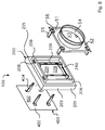
- FIG. 8 shows a second embodiment of a ventilation device according to the invention, which corresponds to the first embodiment, except that on the mounting frame 206, an air nozzle 51 is attached.
- the air nozzle 51 has a connection plate 52, in which a connection opening 53 is formed, at the edge of a tubular or annular projection 54 is attached.
- connection plate 52 is fastened by means of fastening elements 55 releasably attached to the mounting frame 206, so that the connection opening 53 is aligned with the mounting opening 207 and coaxial with the longitudinal axis A.
- the fasteners 55 may be angular elements that can be inserted into tabs 208, 56 and provide a firm hold of the air nozzle to the carrier 200.
- Each angle element is in this case in a tab 56 which is formed on the terminal plate 52, and a corresponding tab 208, which is formed on the carrier 200 introduced.
- the tabs 208 may be at the back of the mounting frame 206, d. H. the side of the mounting frame 206, which faces away from the attachment opening 207 may be formed.
- the connection plate is held at a distance F from the mounting frame 206.
- a circumferential mounting frame web 209 may be formed, the voltage from the mounting frame 206 in the Befest Trentsöff 207 extends orthogonal to the longitudinal axis A.
- the extent of the connection plate 52 in the orthogonal direction to the longitudinal axis A may correspond to the extension of the mounting frame.
- the inner edge of the mounting frame web 209 may be formed in alignment with the carrier frame web 205. This corresponds to the extent of the air passage opening 228 of the attachment opening 207. Both openings are formed coaxially with each other.
- the carrier 200 is formed as a carrier housing 210, the four opposite side walls 211a, 211b, 211c and 211d and a front wall 212 and a rear wall 213 has.
- the side wall 211a is the upper side
- the side wall 211b is the lower side
- the side walls 211c and 211d are the vertical sides of the carrier housing 210.
- the references "top” and “bottom” relate on the floor 900.
- the support frame 201 is formed, wherein three walls of the support frame 201 are formed by the side walls 211a, 211c and 211d of the support housing 210.
- the fourth lower wall of the support frame 201 is disposed above the lower side 211b. Between the fourth wall of the support frame 201 and the bottom 211b of the support housing 210, the support housing is closed by means of the front wall 212.
- a housing opening 215 is formed, which is arranged coaxially to the carrier opening 204, with respect to the longitudinal axis A.
- the housing opening 215 is located in a region which is adjacent to the upper side 211 a and the side walls 211 c and 211d and spaced from the lower side 211 b to the level of the fourth, lower wall of the support frame 201.
- the extent of the housing opening 215 should at least correspond to the extent of the air passage opening 228 of the carrier 200.
- the rear wall 213 is closed. Thereby, a chamber 214 is obtained between the rear wall 213 and the front wall 212 which is bounded below by the side wall 211b and at the sides by the side walls 211c and 211d.
- the lighting element 61 has a U-shaped cross-section and can be inserted into the chamber 214 with an exact fit.
- the legs of the lighting element 61 abut against the rear wall 213 and the front wall 212, respectively, while the base of the lighting element 61 rests against the side wall 211b.
- the lighting means 62 is arranged, in such a way that it does not protrude beyond the legs thereof.
- the formation of the chamber 214 in the carrier housing 210 allows the illumination means to be arranged so that it is not visible through the gap 800 and does not obstruct the air flow.
- the mounting frame 206 On the rear wall 213 may, as in Fig. 9 shown, the mounting frame 206 may be attached. That is not necessary.
- the attachment opening 207 should be aligned with the housing opening 215.
- an air nozzle 51 On the mounting frame 206 and an air nozzle 51 may be attached.
- the air nozzle 51 and the manner of its attachment to the mounting frame 26 correspond to those in Fig. 8 shown embodiment.
Landscapes
- Engineering & Computer Science (AREA)
- Chemical & Material Sciences (AREA)
- Combustion & Propulsion (AREA)
- Mechanical Engineering (AREA)
- General Engineering & Computer Science (AREA)
- Air-Flow Control Members (AREA)
- Arrangement Of Elements, Cooling, Sealing, Or The Like Of Lighting Devices (AREA)
Abstract
Description
- Die Erfindung betrifft eine Lüftungsvorrichtung zur Anbringung an einer Wandöffnung, insbesondere an einer Wandöffnung einer Heizvorrichtung wie eines Ofens. Sie betrifft ferner einen Ofen, der eine solche Lüftungsvorrichtung aufweist.
- Es sind Heizvorrichtungen, insbesondere Öfen, bekannt, in deren Wände Öffnungen eingebracht sind. Die Wandöffnungen können der Zufuhr von Luft aus der Umgebung in die Heizvorrichtung oder der Abfuhr von Luft aus der Heizvorrichtung dienen. Öfen können gemauerte Wände besitzen. Oberhalb des Brennraumes ist häufig eine Wandöffnung vorgesehen, durch die Luft, die im Ofen erwärmt worden ist, in die Umgebung - das ist in der Regel der Raum, in dem sich der Ofen befindet - austreten kann. Zur Abdeckung der Wandöffnungen sind Lüftungsgitter bekannt. Mittels der Lüftungsgitter wird zum einen die Wandöffnung gegen zweckfremde Eingriffe gesichert, zum anderen erlaubt das Lüftungsgitter auch eine Regelung der Wärmeabgabe an die Umgebung.
- Aus
DE 20 2010 001 764 U1 ist ein Lüftungsgitter bekannt, das an Maueröffnungen von Kaminöfen eingebracht werden kann. Das Lüftungsgitter weist einen Rahmen auf, in dem mittig eine Öffnung ausgebildet ist. Die Öffnung kann mit sechs parallel angeordneten, leistenförmigen Klappen verschlossen und geöffnet werden. Die Klappen können mittels eines Schwenkhebels derart verstellt werden, dass die Verstellung einer Klappe die Verstellung aller weiteren Klappen bewirkt. An der Rückseite des Rahmens sind Klemmen befestigt, die mittels Federn eine Klemmbefestigung des Lüftungsgitters in der Maueröffnung ermöglichen sollen. - Das in
DE 20 2010 001 764 U1 offenbarte Lüftungsgitter ist mechanisch anspruchsvoll und wartungsaufwändig. Das Verstellen der sechs leistenförmigen Klappen, um die Öffnung zu verschließen oder zu öffnen, erfordert den Zugriff auf eine der Klappen. Die zum Verstellen aller sechs Klappen auf die eine gegriffene Klappe auszuübende Kraft kann eine Deformation dieser Klappe bewirken, was schließlich zu einer Beschädigung des Lüftungsgitters führt. Eine Einstellung der Luftzufuhr ist dann nicht mehr möglich. Schwergängige und gar nicht mehr stellbare Lüftungsgitter sind aus der Praxis zur Genüge bekannt. Außerdem wird die Abdeckung einer Maueröffnung eines Kaminofens mittels Lüftungsgittern, die leistenförmige Klappen aufweisen, heutigen ästhetischen Vorstellungen nicht oder zumindest nicht vollkommen gerecht. - Aufgabe der Erfindung ist es, die Nachteile nach dem Stand der Technik zu beseitigen. Es soll insbesondere eine Lüftungsvorrichtung zur Anbringung an einer Wandöffnung angegeben werden, die eine mechanisch weniger anspruchsvolle Einstellung des Luftstromes erlaubt, dauerhafter als bekannte Lüftungsgitter ist, eine einfachere Montage ermöglicht und darüber hinaus heutigen ästhetischen Vorstellungen gerecht wird. Es soll ferner ein Ofen mit einer solchen Lüftungsvorrichtung angegeben werden.
- Diese Aufgabe wird durch die Merkmale der Ansprüche 1 und 6 gelöst. Zweckmäßige Ausgestaltungen der Erfindungen ergeben sich aus den Merkmalen der Unteransprüche.
- Nach Maßgabe der Erfindung ist eine Lüftungsvorrichtung zur Anbringung an einer Wandöffnung, insbesondere einer Wandöffnung eines Ofens, vorgesehen. Dabei weist die Lüftungsvorrichtung auf:
- einen Träger (200) mit einem Trägerrahmen (201), dessen Vorderseite (202) eine Trägeröffnung (204) umgibt und dessen Rückseite (203) der Wandung der Wandöffnung zugewandt ist, wobei der Trägerrahmen (201) einen umlaufenden, sich in die Trägeröffnung (204) unter Ausbildung einer Luftdurchtrittsöffnung (228) erstreckenden Trägerrahmen-Steg (205) aufweist und der Trägerrahmensteg (205) zumindest eine Halteleiste (226) aufweist, die an dem Trägerrahmen-Steg (205) befestigt ist; und
- eine Deckplatte (400) mit einer Rückseite (402), die der Luftdurchtrittsöffnung (228) zugewandt ist und an der ein Stellelement (404) zur lösbaren Befestigung an der Halteleiste (226) des Trägerrahmen-Steges (205) ausgebildet ist, das eine Variation des Abstandes zwischen der Deckplatte (400) und der Luftdurchtrittsöffnung (228) ermöglicht.
- Die Wandöffnung ist von einer Wand umgeben. Bei der Wand kann es sich beispielsweise um eine Mauer, eine Betonwand oder eine Trockenbauwand handeln, wobei die Aufzählung nicht abschließend ist. Die Wandöffnung hat eine Breite, Höhe und Tiefe. Die Höhe der Wandöffnung ist dabei deren Ausdehnung in vertikaler Richtung, die Breite deren Ausdehnung in horizontaler Richtung und die Tiefe in orthogonaler Richtung zur Höhe und Breite. Dabei bezeichnet die Tiefe der Wandöffnung den Abstand zwischen den sich gegenüberliegenden Wandflächen. Im Folgenden beziehen sich die Angaben Breite, Höhe und Tiefe auf dieses Koordinatensystem. Der Ausdruck koaxial bezieht sich auf die Achse der jeweiligen Öffnungen, die sich in Tiefenrichtung erstreckt.
- Vorzugsweise liegt der Trägerrahmen mit seiner Rückseite an der Wandung der Wandöffnung an. Auf diese Weise wird verhindert, dass Luft zwischen der Wandung der Wandöffnung und der Rückseite des Trägerrahmens hindurchtreten kann. Der Trägerrahmen ist vorzugsweise rechteckig oder quadratisch. Der Träger kann aus Metall, beispielsweise Stahl, bestehen. Er kann lackiert sein.
- Vorzugsweise weist der Träger zwei parallele, voneinander beabstandete Halteleisten auf, die auf gleiche Weise an dem Trägerrahmen-Steg befestigt sind. Die Längskanten beider Halteleisten sollten von dem Trägerrahmen-Steg beabstandet sein.
- In jeder Halteleiste sollte zumindest eine Leistenöffnung ausgebildet sein, in die Eingreifelemente, beispielsweise Rastelemente oder Rastnasen, eines Stellelementes eingreifen können. Vorzugsweise ist die Leistenöffnung schlitzförmig. Vorzugsweise sind in jeder Halteleiste zwei voneinander beabstandete Leistenöffnungen ausgebildet. Sind zwei Halteleisten vorgesehen, so sind an der Deckplatte vier Stellelemente ausgebildet. Mittels der Stellelemente kann der Abstand zwischen der Deckplatte und der Luftdurchtrittsöffnung variiert werden. Liegt die Deckplatte an dem Trägerrahmensteg an, so ist die Luftdurchtrittsöffnung verschlossen. Damit kann keine Luft durch die Maueröffnung hindurch gelangen. Liegt die Deckplatte nicht an dem Trägerrahmensteg an, so ist die Luftdurchtrittsöffnung geöffnet. Damit kann Luft durch die Maueröffnung hindurch gelangen. Ein Luftstrom kann dann beispielsweise durch die Luftdurchtrittsöffnung in die Trägeröffnung eintreten und von dort in die Umgebung gelangen.
- Bei den Stellelementen kann es sich um Streben handeln. In den Streben können Rastnasen ausgebildet sein, die einen Eingriff in die Leistenöffnungen ermöglichen. Rasten die Stellelemente mit der Rastnase, die der Deckplatte am nächsten liegt, in den Leistenöffnungen ein, so ist der Abstand zwischen der Deckplatte und der Luftdurchtrittsöffnung am geringsten. Rasten die Stellelemente mit der Rastnase, die von der Deckplatte am weitesten entfernt liegt, in den Leistenöffnungen ein, so ist der Abstand zwischen der Deckplatte und der Luftdurchtrittsöffnung am größten. Weisen die Stellelemente jeweils eine, zwei oder mehr Rastnasen auf, so können sie auch als Rastelemente bezeichnet werden, die in die Leistenöffnungen eingreifen. In der Ausführungsform mit vier Stellelementen ist es überdies möglich, den Luftstrom auch in eine spezielle Richtung zu lenken, indem jeweils zwei parallel angeordnete Stellelemente in Bezug auf die beiden anderen, parallel angeordneten Stellelemente in unterschiedliche Tiefen in die Rastnasen eingeführt werden. Somit kann durch Eingriff der beiden unteren Stellelemente mit der Rastnase, die der Deckplatte am nächsten liegt, in den Leistenöffnungen ein Verschluss an der unteren Kante der Deckplatte und durch Eingriff der oberen Stellelemente mit der Rastnase, die von der Deckplatte am weitesten entfernt liegt, in den Leistenöffnungen eine Öffnung an der oberen Kante der Deckplatte und damit ein Lenken des Luftstroms nach oben erreicht werden.
- Es kann vorgesehen sein, dass ein vollständiger Verschluss der Luftdurchtrittsöffnung nicht möglich ist. Dazu kann ein Mindestabstand zwischen der Luftdurchtrittsöffnung und der Deckplatte vorgesehen sein. In diesem Fall kann die Rastnase der Stellelemente, die der Deckplatte am nächsten liegt, so angeordnet sein, dass der Mindestabstand erhalten wird.
- Die Deckplatte ist so dimensioniert, dass sie die Luftdurchtrittsöffnung verschließen kann. Die Deckplatte kann in der Trägeröffnung zum Variieren des Abstandes zwischen ihr und der Luftdurchtrittsöffnung bewegt werden.
- Die Deckplatte kann aus Metall, beispielsweise Stahl, oder Glas bestehen. Besteht sie aus Metall, so kann sie lackiert sein. Es kann aber auch vorgesehen sein, dass auf die Flächenseite der Deckplatte, die der Luftdurchtrittsöffnung abgewandt und damit der Umgebung zugewandt ist, eine Lage aus einem Material aufgebracht ist, das dem der Oberfläche der Wand an deren der Umgebung zugewandter Seite entspricht. Bei der Lage kann es sich beispielsweise um eine Putzlage, beispielsweise eine Putzlage aus einem Mörtelputz, handeln. Damit gleicht die Deckplatte äußerlich der Oberfläche der Wand, was ästhetisch erwünscht sein kann. Die Stellelemente können aus Metall, beispielsweise Stahl, bestehen.
- Es kann weiterhin vorgesehen sein, dass der Träger einen Befestigungsrahmen für zumindest einen Luftstutzen aufweist, der eine Befestigungsöffnung umgibt und sich von dem Trägerrahmen weg erstreckt. Dabei ist die Befestigungsöffnung fluchtend zu der Trägeröffnung ausgebildet. An dem Befestigungsrahmen kann der Luftstutzen mittels Befestigungselementen lösbar befestigt sein. Die Befestigungsöffnung kann fluchtend zur Trägeröffnung ausgebildet sein. Der Befestigungsrahmen kann mehrere Befestigungsöffnungen umgeben. Bei den Befestigungselementen kann es sich um Klammern handeln. Der Befestigungsrahmen kann aus Metall, beispielsweise Stahl, bestehen.
- Der Luftstutzen kann einen ringförmigen Ansatz aufweisen, der sich von einer Anschlussöffnung in einer Anschlussplatte erstreckt, wobei die Anschlussplatte mittels der Befestigungselemente von dem Befestigungsrahmen derart beabstandet gehalten wird, dass die Anschlussplatte nicht an dem Befestigungsrahmen anliegt. Damit entsteht ein Spalt zwischen der Anschlussplatte und dem Befestigungsrahmen, so dass der Luftstutzen von Warmluft aus dem Ofen, der Stauwärme, umspült werden kann. Diese Stauwärme kann somit in die Umgebung transportiert werden. Der Luftstutzen, die Anschlussplatte und die Befestigungselemente können aus Metall, beispielsweise Stahl, bestehen. Sie können schwarz sein. An dem Luftstutzen kann eine Rohrleitung, beispielsweise eine in dem Ofen verlaufende Rohrleitung, angeschlossen sein, in der Luft durch den Ofen transportiert wird.
- In einer Ausführungsform der Erfindung ist in dem Träger zumindest ein Beleuchtungselement angeordnet. Das Beleuchtungselement kann in der Trägeröffnung angeordnet sein. Dabei kann das Beleuchtungselement von dem Trägerrahmen-Steg verdeckt sein. Damit entsteht ein Raum zwischen dem Trägerrahmen-Steg und dem Trägerrahmen-Steg, in dem das Beleuchtungselement an dem Trägerrahmen befestigt sein kann. Ferner kann in dem Träger ein Reflexionselement angeordnet sein, das eine spiegelnde Oberfläche besitzt und das von dem Beleuchtungselement emittierte Licht reflektieren kann. Vorzugsweise ist das Reflexionselement ebenfalls in dem genannten Raum gegenüber dem Beleuchtungselement an dem Trägerrahmen befestigt. Das Beleuchtungselement kann aber auch in einer Kammer angeordnet sein, die in einem Trägergehäuse des Trägers ausgebildet ist. Das Trägergehäuse weist an seiner Vorderwand den Trägerrahmen mit der Trägeröffnung und an seiner Rückwand eine Gehäuseöffnung auf. Zwischen der Vorderseite und der Rückwand des Gehäuses ist eine Kammer ausgebildet, in der das Beleuchtungselement eingesetzt ist.
- Die erfindungsgemäße Lüftungsvorrichtung ermöglicht eine einfache Montage an einer Wandöffnung, insbesondere der Wandöffnung eines Ofens. Zunächst wird der Ofen mit der Wand errichtet, in der sich die Wandöffnung befindet. Anschließend kann der Träger in die Wandöffnung eingesetzt werden. Anschließend kann die Deckplatte an dem Träger angebracht werden, indem Stellelemente in die Leistenöff nungen der Halteleisten eingeführt werden.
- Nach Maßgabe der Erfindung ist ferner ein Ofen vorgesehen, der die erfindungsgemäße Lüftungsvorrichtung aufweist. Dazu kann die erfindungsgemäße Lüftungsvorrichtung in einer Wandöffnung eingesetzt sein, die einen Austritt von Warmluft aus dem Ofen ermöglicht. Bei der Wand kann es sich um eine Mauer handeln. Die erfindungsgemäße Lüftungsvorrichtung kann jedoch auch für andere Zwecke eingesetzt werden. Sie ist beispielsweise für andere Heizvorrichtungen geeignet, bei denen eine Wandöffnung existiert, an der die erfindungsgemäße Lüftungsvorrichtung angebracht werden kann. Sie kann ebenso an Wandöffnungen angebracht werden, die der Luftzufuhr, der Luftabfuhr oder beidem dienen. Beispielsweise kann die erfindungsgemäße Lüftungsvorrichtung an einer Wandöffnung von Kanälen angebracht werden, die einem Raum Frischluft, Warmluft oder Kaltluft zuführen sollen oder Luft aus dem Raum abführen sollen.
- Die Erfindung wird nachstehend anhand von Ausführungsbeispielen, die die Erfindung nicht einschränken sollen, unter Bezugnahme auf die Zeichnungen näher erläutert. Dabei zeigen
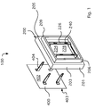
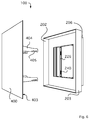
- Fig. 1
- eine Explosionsdarstellung einer ersten Ausführungsform einer erfindungsgemäßen Lüftungsvorrichtung;
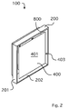
- Fig. 2
- eine perspektivische Darstellung der ersten Ausführungsform einer erfindungsgemäßen Lüftungsvorrichtung;
- Fig. 3
- eine Draufsicht auf die erste Ausführungsform einer erfindungsgemäßen Lüftungsvorrichtung nach deren Montage an einer Öffnung in einer Wand;
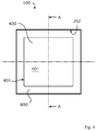
- Fig. 4
- eine Ansicht der ersten Ausführungsform einer erfindungsgemäßen Lüf tungsvorrichtung;
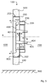
- Fig. 5
- eine Schnittdarstellung der ersten Ausführungsform einer erfindungsgemäßen Lüftungsvorrichtung entlang Schnittlinie A-A von
Fig. 4 ; - Fig. 6
- eine weitere Explosionsdarstellung der ersten Ausführungsform der erfindungsgemäßen Lüftungsvorrichtung;
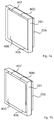
- Fig. 7a - f
- perspektivische Darstellungen der ersten Ausführungsform der erfindungsgemäßen Lüftungsvorrichtung mit unterschiedlich eingesetzter Deckplatte; und
- Fig. 8
- eine perspektivische Darstellung der zweiten Ausführungsform einer erfindungsgemäßen Lüftungsvorrichtung;
- Fig. 9
- eine Explosionsdarstellung einer dritten Ausführungsform einer erfindungsgemäßen Lüftungsvorrichtung.
- Die in den
Figuren 1 bis 7 gezeigte erste Ausführungsform einer erfindungsgemäßen Lüftungsvorrichtung 1 weist einen Träger 200 und eine Deckplatte 400 auf. Der Träger 200 besitzt einen Trägerrahmen 201, dessen Vorderseite 202 die Trägeröffnung 204 umgibt. Die Rückseite 203 des Trägerrahmens 201 liegt an der Wandung einer Öffnung in einer Wand 500 an (sieheFig. 3 ). Der Trägerrahmen 201 ist in der gezeigten Ausführungsform quadratisch ausgebildet. Die inFig. 3 gezeigte Wand 5 ist eine vertikale Wand, die einen Innenraum 600, beispielsweise ein Wohnzwecken dienendes Zimmer, von einem Warmluftbereich 700 eines Ofens trennt (sieheFig. 5 ). In einer Öffnung in der Wand 500 ist die erfindungsgemäße Lüftungsvorrichtung 100 derart eingebaut, dass die Deckplatte 400 dem Innenraum 600 zugewandt ist. - Der Träger 200 weist Halteleisten 226 auf, an denen die Deckplatte 400 lösbar befestigt werden kann. Die Halteleisten 226 sind an einem Trägerrahmen-Steg 205 befestigt, der am Träger 200 ausgebildet ist und sich orthogonal zum Trägerrahmen 201 in die Trägeröffnung 204 erstreckt. Der Trägerrahmen-Steg 205 umgrenzt eine Luftdurchtrittsöffnung 228. Die Halteleisten 36 müssen nicht zwingend an dem Trägerrahmen-Steg 205 befestigt sein. Sie können ebenso an dem Trägerrahmen 201 befestigt sein.
- In der in den
Figuren 1 bis 7 gezeigten ersten Ausführungsform sind zwei Halteleisten 226 vorgesehen. Die Halteleisten 226 sind über Abstandselemente 239, die an zwei gegenüberliegenden Kanten des Trägerrahmen-Steges 205 ausgebildet sind, an dem Trägerrahmen-Steg 205 befestigt. Die Abstandselemente 239 erstrecken sich in einer Richtung parallel zur Längsachse A und erlauben es, die Halteleisten in einer Position an dem Träger 200 zu halten, die nicht in der Trägeröffnung 204 liegt. In der in denFiguren 1 bis 7 gezeigten Ausführungsform erstrecken sich die Abstandselemente 239 in Richtung des Warmluftbereiches 700. Damit befinden sich die Halteleisten 226 in einer Position, die im Warmluftbereich 700 liegt. Die beiden Halteleisten 226 sind mit ihren Längskanten voneinander und von dem Trägerrahmen-Steg 205 beabstandet. In den Halteleisten 226 sind jeweils zwei voneinander beabstandete Leistenöffnungen 240 ausgebildet. An den Halteleisten 226 kann die Deckplatte 400 verstellbar befestigt werden. - Die Deckplatte 400 weist eine Vorderseite 401 und eine Rückseite 402 auf. Ist die Deckplatte 400 in den Träger 200 eingesetzt, so ist die Vorderseite 401 dem Innenraum 600 und die Rückseite 402 dem Warmluftbereich 700 zugewandt. Dabei befindet sich die Deckplatte 4 in der Trägeröffnung 204. Die Deckplatte 4 ist so dimensioniert, dass ein Spalt 800 zwischen dem Rand 403 der Deckplatte 400 und der Vorderseite 202 des Trägers 200 ausgebildet ist, wenn die Deckplatte 400 in den Träger eingesetzt ist. Durch diesen Spalt 800 kann Luft, die aus dem Warmluftbereich 700 über die Luftdurchtrittsöffnung 228 in die Trägeröffnung 204 gelangt (Pfeil B), aus der Trägeröffnung 204 in den Innenraum 600 austreten (Pfeile C). Der Spalt 800 läuft zweckmäßigerweise um den gesamten Rand 403 der Deckplatte 400 herum. Dazu kann die Deckplatte 400 koaxial in der Trägeröffnung 204 angeordnet sein.
- Der Abstand D zwischen den Rückseite 402 der Deckplatte 400 kann mittels Stellelementen 404 verändert werden. Je geringer dieser Abstand ist, desto weniger Luft kann durch den Spalt 800 in den Innenraum 600 gelangen. Liegt die Deckplatte 400 mit ihrer Rückseite 402 an dem Trägerrahmen-Steg 205 an, so ist die Luftdurchtrittsöffnung 228 vollständig verschlossen. Die Deckplatte 400 ist daher nicht nur so dimensioniert, dass der Spalt 800 zwischen dem Rand 403 der Deckplatte 400 und der Vorderseite 202 des Trägers 200 ausgebildet ist, sondern auch so, dass sie die Luftdurchtrittsöffnung 228 verschließt, wenn sie auf dem Trägerrahmen-Steg 205 anliegt. Die Ausdehnung der Deckplatte 400 orthogonal zur Längsachse A der Lüftungsvorrichtung 100 ist daher größer als die Ausdehnung der Luftdurchtrittsöffnung 228 und kleiner als die Ausdehnung der Trägeröffnung 204, jeweils in orthogonaler Richtung zur Längsachse A der Lüftungsvorrichtung 100.
- An der Rückseite 402 der Deckplatte 400 sind vier leistenförmige Stellelemente 404 ausgebildet. Die Stellelemente 404 erstrecken sich dabei parallel zur Längsachse A der Lüftungsvorrichtung 100, wenn die Deckplatte 400 in den Träger 200 eingesetzt ist. Dabei sind die Stellelemente 404 durch die Leistenöffnungen 240 geführt. In den Stellelementen 404 sind Rastnasen 405 ausgebildet, die das Einhängen der Stellelemente 404 in den Leistenöffnungen 240 ermöglichen. Die Rastnasen sind an der Unterkante 406 der Stellelemente 404 ausgebildet. Die Unterkante 406 ist dabei die Kante, die dem Boden 900 zugewandt ist. Je größer die Zahl der Rastnasen 405, desto größer ist die Zahl der Abstände D, die zwischen der Rückseite 402 der Deckplatte 400 und der Luftdurchtrittsöffnung 228 eingestellt werden kann.
- An der Seite des Trägerrahmen-Steges 205, die dem Trägerrahmen 201 abgewandt ist, kann ein Befestigungsrahmen 206 angebracht sein, der eine Befestigungsöffnung 207 umgibt, die fluchtend zu der Trägeröffnung, koaxial zur Längsachse A ausgebildet ist. Ein Befestigungsrahmen 206 ist nicht zwingend erforderlich. Er dient zur Befestigung eines Luftstutzens 51 (siehe
Fig. 8 ). Der Befestigungsrahmen 206 kann an dem Trägerrahmen beabstandet zu den Kanten des Trägerrahmens ausgebildet sein. Damit ist die Befestigungsöffnung 207 größer als die vom Trägerrahmen-Steg 25 umgrenzte Öffnung. - Die
Figuren 7a bis f zeigen die erfindungsgemäße Lüftungsvorrichtung 100, bei der die Deckplatte 400 mit vier Stellelementen 404 und der Träger 200 mit zwei Halteleisten 226 mit jeweils zwei Leistenöffnungen 240 ausgestattet ist. In diesen Darstellungen ist die Deckplatte 400 mit ihren jeweiligen Stellelementen 404 in die jeweiligen Leistenöffnungen 240 der Halteleisten 226 in unterschiedlichen Tiefen eingesetzt. InFig. 7a sind die Stellelemente 404 der Deckplatte 400 mit der Rastnase 405, die der Deckplatte am nächsten liegt, in den Leistenöffnungen 240 eingesetzt, wodurch ein Verschluss der Luftdurchtrittsöffnung 228 erreicht wird. In denFig. 7b und7c sind die Stellelemente 404 der Deckplatte 400 mit jeweils den Rastnasen 405, die von der Deckplatte weiter entfernt liegen, in den Leistenöffnungen 240 eingesetzt, wodurch eine veränderbare Menge des Luftdurchtritts erreicht wird. InFig. 7e sind die beiden unteren Stellelemente 404 der Deckplatte 400 mit den jeweiligen Rastnasen 405, die der Deckplatte am nächsten liegt, in die beiden unteren Leistenöffnungen 240 eingesetzt, und sind die beiden oberen Stellelemente 404 der Deckplatte 400 mit den jeweiligen Rastnasen 405, die von der Deckplatte am weitesten entfernt liegen, in die beiden oberen Leistenöffnungen 240 eingesetzt. Dadurch wird die Unterkante 406 der Deckplatte 400 verschlossen und die Oberkante 407 der Deckplatte erzeugt den maximalen Luftdurchtritt. Somit lässt sich bei dieser Art des Einsetzens der Deckplatte 400 in den Träger 200 ein Luftstrom zur Decke des Raumes hin erzeugen. Durch das Einsetzen der Deckplatte 400 in den Träger 200 in umgekehrter Weise ist ein Luftstrom zum Boden des Raumes hin möglich (Fig. 7f ). -
Figur 8 zeigt eine zweite Ausführungsform einer erfindungsgemäßen Lüftungsvorrichtung, die der ersten Ausführungsform entspricht, außer dass an dem Befestigungsrahmen 206 ein Luftstutzen 51 befestigt ist. Dazu weist der Luftstutzen 51 eine Anschlussplatte 52 auf, in der eine Anschlussöffnung 53 ausgebildet ist, an deren Rand ein rohr- oder ringförmiger Ansatz 54 befestigt ist. - Die Anschlussplatte 52 ist mittels Befestigungselementen 55 lösbar an dem Befestigungsrahmen 206 befestigt, so dass die Anschlussöffnung 53 fluchtend zur Befestigungsöffnung 207 und koaxial zur Längsachse A liegt. Die Befestigungselemente 55 können dabei Winkelelemente sein, die in Laschen 208, 56 eingeführt werden können und für einen festen Halt des Luftstutzens an dem Träger 200 sorgen. Jedes Winkelelement ist dabei in eine Lasche 56, die an der Anschlussplatte 52 ausgebildet ist, und eine korrespondierende Lasche 208, die an dem Träger 200 ausgebildet ist, eingeführt. Die Laschen 208 können dabei an der Rückseite des Befestigungsrahmens 206, d. h. der Seite des Befestigungsrahmens 206, die der Befestigungsöffnung 207 abgewandt ist, ausgebildet sein. Die Anschlussplatte wird dabei in einem Abstand F von dem Befestigungsrahmen 206 gehalten.
- An dem Befestigungsrahmen 26 kann ein umlaufender Befestigungsrahmen-Steg 209 ausgebildet sein, der sich von dem Befestigungsrahmen 206 in die Befestigungsöff nung 207 orthogonal zur Längsachse A erstreckt. Die Ausdehnung der Anschlussplatte 52 in orthogonaler Richtung zur Längsachse A kann der Ausdehnung des Befestigungsrahmens entsprechen. Die Innenkante des Befestigungsrahmen-Stegs 209 kann fluchtend zum Trägerrahmen-Steg 205 ausgebildet sein. Damit entspricht die Ausdehnung der Luftdurchtrittsöffnung 228 der Befestigungsöffnung 207. Beide Öffnungen sind koaxial zueinander ausgebildet.
- Die in
Fig. 9 gezeigte dritte Ausführungsform entspricht der ersten Ausführungsform, außer dass in dem Träger 200 ein Beleuchtungselement 61 mit einem Beleuchtungsmittel 62 angeordnet ist. Dazu ist der Träger 200 als Trägergehäuse 210 ausgebildet, das vier gegenüberliegende Seitenwände 211a, 211b, 211c und 211d sowie eine Vorderwand 212 und eine Rückwand 213 aufweist. Dabei ist die Seitenwand 211a die Oberseite, die Seitenwand 211b die Unterseite und die Seitenwände 211c und 211d die Vertikalseiten des Trägergehäuses 210. Die Angaben "oben" und "unten" beziehen sich auf den Boden 900. An der Vorderwand 212 ist der Trägerrahmen 201 ausgebildet, wobei drei Wände des Trägerrahmens 201 von den Seitenwänden 211a, 211c und 211d des Trägergehäuses 210 gebildet sind. Die vierte, untere Wand des Trägerrahmens 201 ist oberhalb der Unterseite 211b angeordnet. Zwischen der vierten Wand des Trägerrahmens 201 und der Unterseite 211b des Trägergehäuses 210 ist das Trägergehäuse mittels der Vorderwand 212 geschlossen. In der Rückwand 213 des Trägergehäuses 210 ist eine Gehäuseöffnung 215 ausgebildet, die koaxial zur Trägeröffnung 204, bezogen auf die Längsachse A, angeordnet ist. Die Gehäuseöffnung 215 liegt in einem Bereich, der an die Oberseite 211 a und die Seitenwände 211c und 211d angrenzt und von der Unterseite 211b bis in Höhe der vierten, unteren Wand des Trägerrahmens 201 beabstandet ist. Die Ausdehnung der Gehäuseöffnung 215 sollte wenigstens der Ausdehnung der Luftdurchtrittsöffnung 228 des Trägers 200 entsprechen. Zwischen der Unterseite 211b und der Gehäuseöffnung 215 ist die Rückwand 213 geschlossen. Dadurch wird zwischen der Rückwand 213 und der Vorderwand 212 eine Kammer 214 erhalten, die nach unten durch die Seitenwand 211b und an den Seiten durch die Seitenwände 211c und 211 d begrenzt wird. Das Beleuchtungselement 61 weist einen U-förmigen Querschnitt auf und kann passgenau in die Kammer 214 eingesetzt werden. Dabei liegen die Schenkel des Beleuchtungselementes 61 an der Rückwand 213 bzw. der Vorderwand 212 an, während die Basis des Beleuchtungselementes 61 an der Seitenwand 211b aufliegt. Zwischen den Schenkeln des Beleuchtungselementes 61 ist das Beleuchtungsmittel 62 angeordnet, und zwar derart, dass es nicht über dessen Schenkel hinausragt. Die Ausbildung der Kammer 214 in dem Trägergehäuse 210 erlaubt es, das Beleuchtungsmittel so anzuordnen, dass es durch den Spalt 800 hindurch nicht sichtbar ist und den Luftstrom nicht behindert. - An der Rückwand 213 kann, wie in
Fig. 9 gezeigt, der Befestigungsrahmen 206 angebracht sein. Das ist aber nicht erforderlich. Die Befestigungsöffnung 207 sollte dabei fluchtend zur Gehäuseöffnung 215 liegen. An dem Befestigungsrahmen 206 kann auch ein Luftstutzen 51 angebracht sein. Der Luftstutzen 51 und die Art seiner Anbringung an dem Befestigungsrahmen 26 entsprechen der inFig. 8 gezeigten Ausführungsform. -
- 100
- Lüftungsvorrichtung
- 200
- Träger
- 400
- Deckplatte
- 500
- Wand
- 600
- Innenraum
- 700
- Warmluftbereich
- 800
- Spalt
- 900
- Boden
- 201
- Trägerrahmen
- 202
- Vorderseite
- 203
- Rückseite
- 204
- Trägeröffnung
- 205
- Trägerrahmen-Steg
- 206
- Befestigungsrahmen
- 207
- Befestigungsöffnung
- 208
- Lasche
- 209
- Befestigungsrahmen-Steg
- 210
- Trägergehäuse
- 211
- Seitenwand
- 212
- Vorderwand
- 213
- Rückwand
- 214
- Kammer
- 215
- Gehäuseöffnung
- 226
- Halteleiste
- 228
- Luftdurchtrittsöffnung
- 239
- Abstandselement
- 240
- Leistenöffnung
- 401
- Vorderseite
- 402
- Rückseite
- 403
- Rand
- 404
- Stellelement
- 405
- Rastnase
- 406
- Unterkante
- 407
- Oberkante
- 51
- Luftstutzen
- 52
- Anschlussplatte
- 53
- Anschlussöffnung
- 54
- Ansatz
- 55
- Befestigungselement
- 56
- Lasche
- 61
- Beleuchtungselement
- 62
- Beleuchtungsmittel
Claims (6)
- Lüftungsvorrichtung zur Anbringung an einer Wandöffnung, insbesondere einer Wandöffnung eines Ofens, wobei die Lüftungsvorrichtung (100) aufweist:- einen Träger (200) mit einem Trägerrahmen (201), dessen Vorderseite (202) eine Trägeröffnung (204) umgibt und dessen Rückseite (203) der Wandung der Wandöffnung zugewandt ist, wobei der Trägerrahmen (201) einen umlaufenden, sich in die Trägeröffnung (204) unter Ausbildung einer Luftdurchtrittsöffnung (228) erstreckenden Trägerrahmen-Steg (205) aufweist und der Trägerrahmensteg (205) zumindest eine Halteleiste (226) aufweist, die an dem Trägerrahmen-Steg (205) befestigt ist; und- eine Deckplatte (400) mit einer Rückseite (402), die der Luftdurchtrittsöffnung (228) zugewandt ist und an der ein Stellelement (404) zur lösbaren Befestigung an der Halteleiste (226) des Trägerrahmen-Steges (205) ausgebildet ist, das eine Variation des Abstandes zwischen der Deckplatte (400) und der Luftdurchtrittsöffnung (228) ermöglicht.
- Lüftungsvorrichtung nach Anspruch 1, dadurch gekennzeichnet, dass in jeder Halteleiste (226) zumindest eine Leistenöffnung (240) ausgebildet ist, in die Aufnahmen der Stellelemente (404) eingreifen können.
- Lüftungsvorrichtung nach einem der vorstehenden Ansprüche, dadurch gekennzeichnet, dass der Träger (200) einen Befestigungsrahmen (206) für zumindest einen Luftstutzen (51) aufweist, der eine Befestigungsöffnung (207) umgibt und sich von dem Trägerrahmen (201) weg erstreckt, wobei die Befestigungsöffnung (207) fluchtend zu der Trägeröffnung (204) ausgebildet.
- Lüftungsvorrichtung nach Anspruch 3, dadurch gekennzeichnet, dass der Luftstutzen (51) einen ringförmigen Ansatz (54) aufweist, der sich von einer Anschlussöffnung (53) in einer Anschlussplatte (52) erstreckt, wobei die Anschlussplatte (52) mittels der Befestigungselemente (55) von dem Befestigungsrahmen (206) derart beabstandet gehalten ist, dass die Anschlussplatte (52) nicht an dem Befestigungsrahmen (206) anliegt.
- Lüftungsvorrichtung nach einem der vorstehenden Ansprüche, dadurch gekennzeichnet, dass in dem Träger (200) zumindest ein Beleuchtungselement (61) angeordnet ist.
- Ofen mit einer Lüftungsvorrichtung nach einem der Ansprüche 1 bis 5.
Applications Claiming Priority (1)
| Application Number | Priority Date | Filing Date | Title |
|---|---|---|---|
| DE102015115333.5A DE102015115333A1 (de) | 2015-09-11 | 2015-09-11 | Lüftungsvorrichtung und Ofen mit einer solchen Lüftungsvorrichtung |
Publications (2)
| Publication Number | Publication Date |
|---|---|
| EP3141834A1 true EP3141834A1 (de) | 2017-03-15 |
| EP3141834B1 EP3141834B1 (de) | 2020-09-23 |
Family
ID=56411489
Family Applications (1)
| Application Number | Title | Priority Date | Filing Date |
|---|---|---|---|
| EP16179314.6A Active EP3141834B1 (de) | 2015-09-11 | 2016-07-13 | Lüftungsvorrichtung und ofen mit einer solchen lüftungsvorrichtung |
Country Status (2)
| Country | Link |
|---|---|
| EP (1) | EP3141834B1 (de) |
| DE (1) | DE102015115333A1 (de) |
Citations (3)
| Publication number | Priority date | Publication date | Assignee | Title |
|---|---|---|---|---|
| US1679773A (en) * | 1926-10-06 | 1928-08-07 | Arthur F Knowles | Ventilating device |
| US20050227609A1 (en) * | 2004-04-02 | 2005-10-13 | Juergen Koessler | Adjustable vent |
| DE202010001764U1 (de) | 2010-02-09 | 2011-09-12 | Max Blank Gmbh | Lüftungsgitter |
-
2015
- 2015-09-11 DE DE102015115333.5A patent/DE102015115333A1/de active Pending
-
2016
- 2016-07-13 EP EP16179314.6A patent/EP3141834B1/de active Active
Patent Citations (3)
| Publication number | Priority date | Publication date | Assignee | Title |
|---|---|---|---|---|
| US1679773A (en) * | 1926-10-06 | 1928-08-07 | Arthur F Knowles | Ventilating device |
| US20050227609A1 (en) * | 2004-04-02 | 2005-10-13 | Juergen Koessler | Adjustable vent |
| DE202010001764U1 (de) | 2010-02-09 | 2011-09-12 | Max Blank Gmbh | Lüftungsgitter |
Also Published As
| Publication number | Publication date |
|---|---|
| EP3141834B1 (de) | 2020-09-23 |
| DE102015115333A1 (de) | 2017-03-16 |
Similar Documents
| Publication | Publication Date | Title |
|---|---|---|
| EP3118523A1 (de) | Lüftungsvorrichtung und kaminofen mit einer solchen lüftungsvorrichtung | |
| DE202010001764U1 (de) | Lüftungsgitter | |
| DE3012588C2 (de) | Strahlungsbrenner, insbesondere für gasförmigen Brennstoff | |
| EP3686505B1 (de) | Lufteinlass und anordnung zur führung von luft | |
| EP3686494B1 (de) | Lüftungsvorrichtung und heizeinrichtung mit einer solchen lüftungsvorrichtung | |
| DE1604299C3 (de) | Induktionsgerät für Hochdruckklimaanlagen | |
| EP3141834B1 (de) | Lüftungsvorrichtung und ofen mit einer solchen lüftungsvorrichtung | |
| EP3686503B1 (de) | Ofen mit einem luftdurchlass | |
| EP4232758A1 (de) | Verschlusseinheit einer lüftungsvorrichtung | |
| EP3124869B1 (de) | Luftauslassgitter, insbesondere für einen ofen | |
| EP2860467B1 (de) | Luftauslass | |
| DE60121825T2 (de) | Luftverteilungskappe für einen konvektor | |
| EP3236173B1 (de) | Verfahren zum klimatisieren eines raums | |
| EP0801275A2 (de) | Ersatzluftventil | |
| EP3686504A1 (de) | Luftauslass sowie wand und ofen mit einem solchen luftauslass | |
| DE202016001920U1 (de) | Luftführung für einen Haushaltsofen | |
| EP4224077B1 (de) | Luftdurchlass | |
| DE202011108466U1 (de) | Luftzuführvorrichtung zur Raumbelüftung | |
| EP1243870A2 (de) | Heizkörper | |
| DE102007007928A1 (de) | Lufttechnische Einrichtung | |
| DE1454661A1 (de) | Lueftungsjalousie fuer Raumlueftung und Klimatisierung | |
| DE102015010199A1 (de) | Unterflurklimatisierungsvorrichtung | |
| EP4400773A1 (de) | Wärmetauscher und verfahren für dessen nutzung | |
| DE3542383A1 (de) | Kamineinsatz | |
| EP4644782A1 (de) | Umluftweichenvorrichtung für dunstabzugshaube, umluftweiche, versperrelement und dunstabzugsvorrichtung |
Legal Events
| Date | Code | Title | Description |
|---|---|---|---|
| PUAI | Public reference made under article 153(3) epc to a published international application that has entered the european phase |
Free format text: ORIGINAL CODE: 0009012 |
|
| STAA | Information on the status of an ep patent application or granted ep patent |
Free format text: STATUS: THE APPLICATION HAS BEEN PUBLISHED |
|
| AK | Designated contracting states |
Kind code of ref document: A1 Designated state(s): AL AT BE BG CH CY CZ DE DK EE ES FI FR GB GR HR HU IE IS IT LI LT LU LV MC MK MT NL NO PL PT RO RS SE SI SK SM TR |
|
| AX | Request for extension of the european patent |
Extension state: BA ME |
|
| STAA | Information on the status of an ep patent application or granted ep patent |
Free format text: STATUS: REQUEST FOR EXAMINATION WAS MADE |
|
| 17P | Request for examination filed |
Effective date: 20170915 |
|
| RBV | Designated contracting states (corrected) |
Designated state(s): AL AT BE BG CH CY CZ DE DK EE ES FI FR GB GR HR HU IE IS IT LI LT LU LV MC MK MT NL NO PL PT RO RS SE SI SK SM TR |
|
| GRAP | Despatch of communication of intention to grant a patent |
Free format text: ORIGINAL CODE: EPIDOSNIGR1 |
|
| STAA | Information on the status of an ep patent application or granted ep patent |
Free format text: STATUS: GRANT OF PATENT IS INTENDED |
|
| INTG | Intention to grant announced |
Effective date: 20200226 |
|
| GRAJ | Information related to disapproval of communication of intention to grant by the applicant or resumption of examination proceedings by the epo deleted |
Free format text: ORIGINAL CODE: EPIDOSDIGR1 |
|
| STAA | Information on the status of an ep patent application or granted ep patent |
Free format text: STATUS: REQUEST FOR EXAMINATION WAS MADE |
|
| INTC | Intention to grant announced (deleted) | ||
| GRAS | Grant fee paid |
Free format text: ORIGINAL CODE: EPIDOSNIGR3 |
|
| STAA | Information on the status of an ep patent application or granted ep patent |
Free format text: STATUS: GRANT OF PATENT IS INTENDED |
|
| GRAP | Despatch of communication of intention to grant a patent |
Free format text: ORIGINAL CODE: EPIDOSNIGR1 |
|
| GRAA | (expected) grant |
Free format text: ORIGINAL CODE: 0009210 |
|
| STAA | Information on the status of an ep patent application or granted ep patent |
Free format text: STATUS: THE PATENT HAS BEEN GRANTED |
|
| INTG | Intention to grant announced |
Effective date: 20200728 |
|
| AK | Designated contracting states |
Kind code of ref document: B1 Designated state(s): AL AT BE BG CH CY CZ DE DK EE ES FI FR GB GR HR HU IE IS IT LI LT LU LV MC MK MT NL NO PL PT RO RS SE SI SK SM TR |
|
| REG | Reference to a national code |
Ref country code: GB Ref legal event code: FG4D Free format text: NOT ENGLISH |
|
| REG | Reference to a national code |
Ref country code: CH Ref legal event code: EP |
|
| REG | Reference to a national code |
Ref country code: IE Ref legal event code: FG4D Free format text: LANGUAGE OF EP DOCUMENT: GERMAN |
|
| REG | Reference to a national code |
Ref country code: AT Ref legal event code: REF Ref document number: 1316785 Country of ref document: AT Kind code of ref document: T Effective date: 20201015 Ref country code: DE Ref legal event code: R096 Ref document number: 502016011225 Country of ref document: DE |
|
| REG | Reference to a national code |
Ref country code: NL Ref legal event code: FP |
|
| PG25 | Lapsed in a contracting state [announced via postgrant information from national office to epo] |
Ref country code: BG Free format text: LAPSE BECAUSE OF FAILURE TO SUBMIT A TRANSLATION OF THE DESCRIPTION OR TO PAY THE FEE WITHIN THE PRESCRIBED TIME-LIMIT Effective date: 20201223 Ref country code: HR Free format text: LAPSE BECAUSE OF FAILURE TO SUBMIT A TRANSLATION OF THE DESCRIPTION OR TO PAY THE FEE WITHIN THE PRESCRIBED TIME-LIMIT Effective date: 20200923 Ref country code: SE Free format text: LAPSE BECAUSE OF FAILURE TO SUBMIT A TRANSLATION OF THE DESCRIPTION OR TO PAY THE FEE WITHIN THE PRESCRIBED TIME-LIMIT Effective date: 20200923 Ref country code: NO Free format text: LAPSE BECAUSE OF FAILURE TO SUBMIT A TRANSLATION OF THE DESCRIPTION OR TO PAY THE FEE WITHIN THE PRESCRIBED TIME-LIMIT Effective date: 20201223 Ref country code: GR Free format text: LAPSE BECAUSE OF FAILURE TO SUBMIT A TRANSLATION OF THE DESCRIPTION OR TO PAY THE FEE WITHIN THE PRESCRIBED TIME-LIMIT Effective date: 20201224 Ref country code: FI Free format text: LAPSE BECAUSE OF FAILURE TO SUBMIT A TRANSLATION OF THE DESCRIPTION OR TO PAY THE FEE WITHIN THE PRESCRIBED TIME-LIMIT Effective date: 20200923 |
|
| PG25 | Lapsed in a contracting state [announced via postgrant information from national office to epo] |
Ref country code: RS Free format text: LAPSE BECAUSE OF FAILURE TO SUBMIT A TRANSLATION OF THE DESCRIPTION OR TO PAY THE FEE WITHIN THE PRESCRIBED TIME-LIMIT Effective date: 20200923 Ref country code: LV Free format text: LAPSE BECAUSE OF FAILURE TO SUBMIT A TRANSLATION OF THE DESCRIPTION OR TO PAY THE FEE WITHIN THE PRESCRIBED TIME-LIMIT Effective date: 20200923 |
|
| REG | Reference to a national code |
Ref country code: LT Ref legal event code: MG4D |
|
| PG25 | Lapsed in a contracting state [announced via postgrant information from national office to epo] |
Ref country code: EE Free format text: LAPSE BECAUSE OF FAILURE TO SUBMIT A TRANSLATION OF THE DESCRIPTION OR TO PAY THE FEE WITHIN THE PRESCRIBED TIME-LIMIT Effective date: 20200923 Ref country code: PT Free format text: LAPSE BECAUSE OF FAILURE TO SUBMIT A TRANSLATION OF THE DESCRIPTION OR TO PAY THE FEE WITHIN THE PRESCRIBED TIME-LIMIT Effective date: 20210125 Ref country code: SM Free format text: LAPSE BECAUSE OF FAILURE TO SUBMIT A TRANSLATION OF THE DESCRIPTION OR TO PAY THE FEE WITHIN THE PRESCRIBED TIME-LIMIT Effective date: 20200923 Ref country code: RO Free format text: LAPSE BECAUSE OF FAILURE TO SUBMIT A TRANSLATION OF THE DESCRIPTION OR TO PAY THE FEE WITHIN THE PRESCRIBED TIME-LIMIT Effective date: 20200923 Ref country code: CZ Free format text: LAPSE BECAUSE OF FAILURE TO SUBMIT A TRANSLATION OF THE DESCRIPTION OR TO PAY THE FEE WITHIN THE PRESCRIBED TIME-LIMIT Effective date: 20200923 Ref country code: LT Free format text: LAPSE BECAUSE OF FAILURE TO SUBMIT A TRANSLATION OF THE DESCRIPTION OR TO PAY THE FEE WITHIN THE PRESCRIBED TIME-LIMIT Effective date: 20200923 |
|
| PG25 | Lapsed in a contracting state [announced via postgrant information from national office to epo] |
Ref country code: IS Free format text: LAPSE BECAUSE OF FAILURE TO SUBMIT A TRANSLATION OF THE DESCRIPTION OR TO PAY THE FEE WITHIN THE PRESCRIBED TIME-LIMIT Effective date: 20210123 Ref country code: PL Free format text: LAPSE BECAUSE OF FAILURE TO SUBMIT A TRANSLATION OF THE DESCRIPTION OR TO PAY THE FEE WITHIN THE PRESCRIBED TIME-LIMIT Effective date: 20200923 Ref country code: AL Free format text: LAPSE BECAUSE OF FAILURE TO SUBMIT A TRANSLATION OF THE DESCRIPTION OR TO PAY THE FEE WITHIN THE PRESCRIBED TIME-LIMIT Effective date: 20200923 Ref country code: ES Free format text: LAPSE BECAUSE OF FAILURE TO SUBMIT A TRANSLATION OF THE DESCRIPTION OR TO PAY THE FEE WITHIN THE PRESCRIBED TIME-LIMIT Effective date: 20200923 |
|
| REG | Reference to a national code |
Ref country code: DE Ref legal event code: R097 Ref document number: 502016011225 Country of ref document: DE |
|
| PG25 | Lapsed in a contracting state [announced via postgrant information from national office to epo] |
Ref country code: SK Free format text: LAPSE BECAUSE OF FAILURE TO SUBMIT A TRANSLATION OF THE DESCRIPTION OR TO PAY THE FEE WITHIN THE PRESCRIBED TIME-LIMIT Effective date: 20200923 |
|
| PLBE | No opposition filed within time limit |
Free format text: ORIGINAL CODE: 0009261 |
|
| STAA | Information on the status of an ep patent application or granted ep patent |
Free format text: STATUS: NO OPPOSITION FILED WITHIN TIME LIMIT |
|
| PG25 | Lapsed in a contracting state [announced via postgrant information from national office to epo] |
Ref country code: SI Free format text: LAPSE BECAUSE OF FAILURE TO SUBMIT A TRANSLATION OF THE DESCRIPTION OR TO PAY THE FEE WITHIN THE PRESCRIBED TIME-LIMIT Effective date: 20200923 Ref country code: DK Free format text: LAPSE BECAUSE OF FAILURE TO SUBMIT A TRANSLATION OF THE DESCRIPTION OR TO PAY THE FEE WITHIN THE PRESCRIBED TIME-LIMIT Effective date: 20200923 |
|
| 26N | No opposition filed |
Effective date: 20210624 |
|
| GBPC | Gb: european patent ceased through non-payment of renewal fee |
Effective date: 20210713 |
|
| PG25 | Lapsed in a contracting state [announced via postgrant information from national office to epo] |
Ref country code: MC Free format text: LAPSE BECAUSE OF FAILURE TO SUBMIT A TRANSLATION OF THE DESCRIPTION OR TO PAY THE FEE WITHIN THE PRESCRIBED TIME-LIMIT Effective date: 20200923 |
|
| PG25 | Lapsed in a contracting state [announced via postgrant information from national office to epo] |
Ref country code: GB Free format text: LAPSE BECAUSE OF NON-PAYMENT OF DUE FEES Effective date: 20210713 |
|
| PG25 | Lapsed in a contracting state [announced via postgrant information from national office to epo] |
Ref country code: IE Free format text: LAPSE BECAUSE OF NON-PAYMENT OF DUE FEES Effective date: 20210713 |
|
| PG25 | Lapsed in a contracting state [announced via postgrant information from national office to epo] |
Ref country code: HU Free format text: LAPSE BECAUSE OF FAILURE TO SUBMIT A TRANSLATION OF THE DESCRIPTION OR TO PAY THE FEE WITHIN THE PRESCRIBED TIME-LIMIT; INVALID AB INITIO Effective date: 20160713 |
|
| PG25 | Lapsed in a contracting state [announced via postgrant information from national office to epo] |
Ref country code: CY Free format text: LAPSE BECAUSE OF FAILURE TO SUBMIT A TRANSLATION OF THE DESCRIPTION OR TO PAY THE FEE WITHIN THE PRESCRIBED TIME-LIMIT Effective date: 20200923 |
|
| PG25 | Lapsed in a contracting state [announced via postgrant information from national office to epo] |
Ref country code: MK Free format text: LAPSE BECAUSE OF FAILURE TO SUBMIT A TRANSLATION OF THE DESCRIPTION OR TO PAY THE FEE WITHIN THE PRESCRIBED TIME-LIMIT Effective date: 20200923 |
|
| PG25 | Lapsed in a contracting state [announced via postgrant information from national office to epo] |
Ref country code: MT Free format text: LAPSE BECAUSE OF FAILURE TO SUBMIT A TRANSLATION OF THE DESCRIPTION OR TO PAY THE FEE WITHIN THE PRESCRIBED TIME-LIMIT Effective date: 20200923 |
|
| REG | Reference to a national code |
Ref country code: LU Ref legal event code: PD Owner name: SUBTIEL KONTOR GMBH; DE Free format text: FORMER OWNER: DE ZUYLENKAMP B.V. Effective date: 20241220 |
|
| REG | Reference to a national code |
Ref country code: DE Ref legal event code: R081 Ref document number: 502016011225 Country of ref document: DE Owner name: SUBTIEL KONTOR GMBH, DE Free format text: FORMER OWNER: DE ZUYLENKAMP B.V., DOETINCHEM, NL |
|
| REG | Reference to a national code |
Ref country code: BE Ref legal event code: PD Owner name: SUBTIEL KONTOR GMBH; DE Free format text: DETAILS ASSIGNMENT: CHANGE OF OWNER(S), ASSIGNMENT; FORMER OWNER NAME: DE ZUYLENKAMP B.V. Effective date: 20241219 |
|
| REG | Reference to a national code |
Ref country code: AT Ref legal event code: PC Ref document number: 1316785 Country of ref document: AT Kind code of ref document: T Owner name: SUBTIEL KONTOR GMBH, DE Effective date: 20250310 |
|
| REG | Reference to a national code |
Ref country code: NL Ref legal event code: PD Owner name: SUBTIEL KONTOR GMBH; DE Free format text: DETAILS ASSIGNMENT: CHANGE OF OWNER(S), ASSIGNMENT; FORMER OWNER NAME: DE ZUYLENKAMP B.V. Effective date: 20250408 |
|
| PGFP | Annual fee paid to national office [announced via postgrant information from national office to epo] |
Ref country code: NL Payment date: 20250723 Year of fee payment: 10 Ref country code: LU Payment date: 20250722 Year of fee payment: 10 |
|
| PGFP | Annual fee paid to national office [announced via postgrant information from national office to epo] |
Ref country code: DE Payment date: 20250710 Year of fee payment: 10 |
|
| PGFP | Annual fee paid to national office [announced via postgrant information from national office to epo] |
Ref country code: IT Payment date: 20250731 Year of fee payment: 10 |
|
| PGFP | Annual fee paid to national office [announced via postgrant information from national office to epo] |
Ref country code: BE Payment date: 20250722 Year of fee payment: 10 |
|
| PGFP | Annual fee paid to national office [announced via postgrant information from national office to epo] |
Ref country code: AT Payment date: 20250721 Year of fee payment: 10 Ref country code: FR Payment date: 20250723 Year of fee payment: 10 |
|
| PGFP | Annual fee paid to national office [announced via postgrant information from national office to epo] |
Ref country code: CH Payment date: 20250801 Year of fee payment: 10 |
|
| PG25 | Lapsed in a contracting state [announced via postgrant information from national office to epo] |
Ref country code: TR Free format text: LAPSE BECAUSE OF FAILURE TO SUBMIT A TRANSLATION OF THE DESCRIPTION OR TO PAY THE FEE WITHIN THE PRESCRIBED TIME-LIMIT Effective date: 20200923 |