EP3141797A1 - Linienleuchte - Google Patents
Linienleuchte Download PDFInfo
- Publication number
- EP3141797A1 EP3141797A1 EP16187763.4A EP16187763A EP3141797A1 EP 3141797 A1 EP3141797 A1 EP 3141797A1 EP 16187763 A EP16187763 A EP 16187763A EP 3141797 A1 EP3141797 A1 EP 3141797A1
- Authority
- EP
- European Patent Office
- Prior art keywords
- light
- glass
- light guide
- line
- emitting
- Prior art date
- Legal status (The legal status is an assumption and is not a legal conclusion. Google has not performed a legal analysis and makes no representation as to the accuracy of the status listed.)
- Granted
Links
- 238000005286 illumination Methods 0.000 title description 3
- 239000011521 glass Substances 0.000 claims abstract description 109
- 239000000835 fiber Substances 0.000 claims description 31
- 239000013307 optical fiber Substances 0.000 claims description 24
- 230000008878 coupling Effects 0.000 claims description 9
- 238000010168 coupling process Methods 0.000 claims description 9
- 238000005859 coupling reaction Methods 0.000 claims description 9
- 230000005540 biological transmission Effects 0.000 claims description 4
- 239000003365 glass fiber Substances 0.000 abstract description 16
- 229920003023 plastic Polymers 0.000 description 11
- 239000000049 pigment Substances 0.000 description 10
- 239000000463 material Substances 0.000 description 9
- 230000003287 optical effect Effects 0.000 description 9
- 239000004033 plastic Substances 0.000 description 9
- 239000002245 particle Substances 0.000 description 6
- 238000005253 cladding Methods 0.000 description 5
- 239000011257 shell material Substances 0.000 description 5
- 238000004040 coloring Methods 0.000 description 4
- -1 polyethylene Polymers 0.000 description 4
- 239000000853 adhesive Substances 0.000 description 3
- 230000001070 adhesive effect Effects 0.000 description 3
- 238000011161 development Methods 0.000 description 3
- 230000018109 developmental process Effects 0.000 description 3
- 238000009434 installation Methods 0.000 description 3
- 230000000873 masking effect Effects 0.000 description 3
- 229910052751 metal Inorganic materials 0.000 description 3
- 239000002184 metal Substances 0.000 description 3
- 239000004698 Polyethylene Substances 0.000 description 2
- 239000004743 Polypropylene Substances 0.000 description 2
- 239000012876 carrier material Substances 0.000 description 2
- 239000011248 coating agent Substances 0.000 description 2
- 238000000576 coating method Methods 0.000 description 2
- 239000012141 concentrate Substances 0.000 description 2
- 238000009826 distribution Methods 0.000 description 2
- 229920001971 elastomer Polymers 0.000 description 2
- 239000004744 fabric Substances 0.000 description 2
- 239000011888 foil Substances 0.000 description 2
- 229920000092 linear low density polyethylene Polymers 0.000 description 2
- 239000004707 linear low-density polyethylene Substances 0.000 description 2
- 238000005191 phase separation Methods 0.000 description 2
- 229920000573 polyethylene Polymers 0.000 description 2
- 229920001155 polypropylene Polymers 0.000 description 2
- 229920001296 polysiloxane Polymers 0.000 description 2
- 239000005060 rubber Substances 0.000 description 2
- 229910052709 silver Inorganic materials 0.000 description 2
- 239000004332 silver Substances 0.000 description 2
- 238000001228 spectrum Methods 0.000 description 2
- 239000004594 Masterbatch (MB) Substances 0.000 description 1
- 239000004433 Thermoplastic polyurethane Substances 0.000 description 1
- 238000003848 UV Light-Curing Methods 0.000 description 1
- 229910052782 aluminium Inorganic materials 0.000 description 1
- XAGFODPZIPBFFR-UHFFFAOYSA-N aluminium Chemical compound [Al] XAGFODPZIPBFFR-UHFFFAOYSA-N 0.000 description 1
- 230000008901 benefit Effects 0.000 description 1
- 230000008859 change Effects 0.000 description 1
- 239000003795 chemical substances by application Substances 0.000 description 1
- 239000003086 colorant Substances 0.000 description 1
- 239000004020 conductor Substances 0.000 description 1
- 230000001419 dependent effect Effects 0.000 description 1
- 238000002845 discoloration Methods 0.000 description 1
- 230000000694 effects Effects 0.000 description 1
- 238000005516 engineering process Methods 0.000 description 1
- 238000000605 extraction Methods 0.000 description 1
- 239000013305 flexible fiber Substances 0.000 description 1
- 229920002457 flexible plastic Polymers 0.000 description 1
- 230000010354 integration Effects 0.000 description 1
- 239000010985 leather Substances 0.000 description 1
- 238000004519 manufacturing process Methods 0.000 description 1
- 238000000034 method Methods 0.000 description 1
- 238000002156 mixing Methods 0.000 description 1
- TWNQGVIAIRXVLR-UHFFFAOYSA-N oxo(oxoalumanyloxy)alumane Chemical compound O=[Al]O[Al]=O TWNQGVIAIRXVLR-UHFFFAOYSA-N 0.000 description 1
- 239000003973 paint Substances 0.000 description 1
- 238000010422 painting Methods 0.000 description 1
- 230000008569 process Effects 0.000 description 1
- 230000005855 radiation Effects 0.000 description 1
- 230000000191 radiation effect Effects 0.000 description 1
- 238000007670 refining Methods 0.000 description 1
- 238000006748 scratching Methods 0.000 description 1
- 230000002393 scratching effect Effects 0.000 description 1
- 239000005368 silicate glass Substances 0.000 description 1
- 239000004071 soot Substances 0.000 description 1
- 230000003595 spectral effect Effects 0.000 description 1
- 229920002803 thermoplastic polyurethane Polymers 0.000 description 1
- 239000010409 thin film Substances 0.000 description 1
- 238000003325 tomography Methods 0.000 description 1
- 230000007704 transition Effects 0.000 description 1
- 239000012780 transparent material Substances 0.000 description 1
Images


Classifications
-
- F—MECHANICAL ENGINEERING; LIGHTING; HEATING; WEAPONS; BLASTING
- F21—LIGHTING
- F21K—NON-ELECTRIC LIGHT SOURCES USING LUMINESCENCE; LIGHT SOURCES USING ELECTROCHEMILUMINESCENCE; LIGHT SOURCES USING CHARGES OF COMBUSTIBLE MATERIAL; LIGHT SOURCES USING SEMICONDUCTOR DEVICES AS LIGHT-GENERATING ELEMENTS; LIGHT SOURCES NOT OTHERWISE PROVIDED FOR
- F21K9/00—Light sources using semiconductor devices as light-generating elements, e.g. using light-emitting diodes [LED] or lasers
- F21K9/60—Optical arrangements integrated in the light source, e.g. for improving the colour rendering index or the light extraction
- F21K9/61—Optical arrangements integrated in the light source, e.g. for improving the colour rendering index or the light extraction using light guides
-
- B—PERFORMING OPERATIONS; TRANSPORTING
- B60—VEHICLES IN GENERAL
- B60Q—ARRANGEMENT OF SIGNALLING OR LIGHTING DEVICES, THE MOUNTING OR SUPPORTING THEREOF OR CIRCUITS THEREFOR, FOR VEHICLES IN GENERAL
- B60Q1/00—Arrangement of optical signalling or lighting devices, the mounting or supporting thereof or circuits therefor
- B60Q1/26—Arrangement of optical signalling or lighting devices, the mounting or supporting thereof or circuits therefor the devices being primarily intended to indicate the vehicle, or parts thereof, or to give signals, to other traffic
- B60Q1/2696—Mounting of devices using LEDs
-
- B—PERFORMING OPERATIONS; TRANSPORTING
- B60—VEHICLES IN GENERAL
- B60Q—ARRANGEMENT OF SIGNALLING OR LIGHTING DEVICES, THE MOUNTING OR SUPPORTING THEREOF OR CIRCUITS THEREFOR, FOR VEHICLES IN GENERAL
- B60Q1/00—Arrangement of optical signalling or lighting devices, the mounting or supporting thereof or circuits therefor
- B60Q1/26—Arrangement of optical signalling or lighting devices, the mounting or supporting thereof or circuits therefor the devices being primarily intended to indicate the vehicle, or parts thereof, or to give signals, to other traffic
- B60Q1/32—Arrangement of optical signalling or lighting devices, the mounting or supporting thereof or circuits therefor the devices being primarily intended to indicate the vehicle, or parts thereof, or to give signals, to other traffic for indicating vehicle sides, e.g. clearance lights
- B60Q1/325—Arrangement of optical signalling or lighting devices, the mounting or supporting thereof or circuits therefor the devices being primarily intended to indicate the vehicle, or parts thereof, or to give signals, to other traffic for indicating vehicle sides, e.g. clearance lights on or for running boards or steps
-
- B—PERFORMING OPERATIONS; TRANSPORTING
- B60—VEHICLES IN GENERAL
- B60Q—ARRANGEMENT OF SIGNALLING OR LIGHTING DEVICES, THE MOUNTING OR SUPPORTING THEREOF OR CIRCUITS THEREFOR, FOR VEHICLES IN GENERAL
- B60Q3/00—Arrangement of lighting devices for vehicle interiors; Lighting devices specially adapted for vehicle interiors
- B60Q3/20—Arrangement of lighting devices for vehicle interiors; Lighting devices specially adapted for vehicle interiors for lighting specific fittings of passenger or driving compartments; mounted on specific fittings of passenger or driving compartments
- B60Q3/217—Doors, e.g. door sills; Steps
-
- B—PERFORMING OPERATIONS; TRANSPORTING
- B60—VEHICLES IN GENERAL
- B60Q—ARRANGEMENT OF SIGNALLING OR LIGHTING DEVICES, THE MOUNTING OR SUPPORTING THEREOF OR CIRCUITS THEREFOR, FOR VEHICLES IN GENERAL
- B60Q3/00—Arrangement of lighting devices for vehicle interiors; Lighting devices specially adapted for vehicle interiors
- B60Q3/60—Arrangement of lighting devices for vehicle interiors; Lighting devices specially adapted for vehicle interiors characterised by optical aspects
- B60Q3/62—Arrangement of lighting devices for vehicle interiors; Lighting devices specially adapted for vehicle interiors characterised by optical aspects using light guides
- B60Q3/64—Arrangement of lighting devices for vehicle interiors; Lighting devices specially adapted for vehicle interiors characterised by optical aspects using light guides for a single lighting device
-
- B—PERFORMING OPERATIONS; TRANSPORTING
- B60—VEHICLES IN GENERAL
- B60Q—ARRANGEMENT OF SIGNALLING OR LIGHTING DEVICES, THE MOUNTING OR SUPPORTING THEREOF OR CIRCUITS THEREFOR, FOR VEHICLES IN GENERAL
- B60Q3/00—Arrangement of lighting devices for vehicle interiors; Lighting devices specially adapted for vehicle interiors
- B60Q3/70—Arrangement of lighting devices for vehicle interiors; Lighting devices specially adapted for vehicle interiors characterised by the purpose
- B60Q3/78—Arrangement of lighting devices for vehicle interiors; Lighting devices specially adapted for vehicle interiors characterised by the purpose for generating luminous strips, e.g. for marking trim component edges
-
- F—MECHANICAL ENGINEERING; LIGHTING; HEATING; WEAPONS; BLASTING
- F21—LIGHTING
- F21S—NON-PORTABLE LIGHTING DEVICES; SYSTEMS THEREOF; VEHICLE LIGHTING DEVICES SPECIALLY ADAPTED FOR VEHICLE EXTERIORS
- F21S43/00—Signalling devices specially adapted for vehicle exteriors, e.g. brake lamps, direction indicator lights or reversing lights
- F21S43/20—Signalling devices specially adapted for vehicle exteriors, e.g. brake lamps, direction indicator lights or reversing lights characterised by refractors, transparent cover plates, light guides or filters
- F21S43/235—Light guides
- F21S43/242—Light guides characterised by the emission area
- F21S43/245—Light guides characterised by the emission area emitting light from one or more of its major surfaces
-
- G—PHYSICS
- G02—OPTICS
- G02B—OPTICAL ELEMENTS, SYSTEMS OR APPARATUS
- G02B6/00—Light guides; Structural details of arrangements comprising light guides and other optical elements, e.g. couplings
- G02B6/0001—Light guides; Structural details of arrangements comprising light guides and other optical elements, e.g. couplings specially adapted for lighting devices or systems
- G02B6/0005—Light guides; Structural details of arrangements comprising light guides and other optical elements, e.g. couplings specially adapted for lighting devices or systems the light guides being of the fibre type
- G02B6/0006—Coupling light into the fibre
-
- G—PHYSICS
- G02—OPTICS
- G02B—OPTICAL ELEMENTS, SYSTEMS OR APPARATUS
- G02B6/00—Light guides; Structural details of arrangements comprising light guides and other optical elements, e.g. couplings
- G02B6/0001—Light guides; Structural details of arrangements comprising light guides and other optical elements, e.g. couplings specially adapted for lighting devices or systems
- G02B6/0005—Light guides; Structural details of arrangements comprising light guides and other optical elements, e.g. couplings specially adapted for lighting devices or systems the light guides being of the fibre type
- G02B6/001—Light guides; Structural details of arrangements comprising light guides and other optical elements, e.g. couplings specially adapted for lighting devices or systems the light guides being of the fibre type the light being emitted along at least a portion of the lateral surface of the fibre
-
- F—MECHANICAL ENGINEERING; LIGHTING; HEATING; WEAPONS; BLASTING
- F21—LIGHTING
- F21W—INDEXING SCHEME ASSOCIATED WITH SUBCLASSES F21K, F21L, F21S and F21V, RELATING TO USES OR APPLICATIONS OF LIGHTING DEVICES OR SYSTEMS
- F21W2107/00—Use or application of lighting devices on or in particular types of vehicles
- F21W2107/10—Use or application of lighting devices on or in particular types of vehicles for land vehicles
Definitions
- the invention relates to a side emitting line light.
- the invention relates to a line lamp which is used as contour lighting for vehicles, especially as outdoor lighting, use.
- the invention relates to a running board with a line light.
- the line lamp according to the invention can also be used for other applications, in particular in the building and furniture sector.
- Contour lighting is increasingly used, in particular through the spread of LED technology. This also applies, among other things, to the vehicle sector.
- the document DE 20 2008 011 063 U1 shows a lighting device for vehicles, which is intended in particular as a footboard lighting.
- contour lighting for vehicles is usually their complex installation.
- Matt an installation in a housing.
- this must also be designed to be water- and dust-proof.
- the invention is based on the object to provide a line light, which is robust and can be installed in a simple manner.
- the line lamp according to the invention should be as little as possible visible.
- the invention relates to a line luminaire, that is to say a luminaire in which the light is emitted along a line.
- This line is preferably straight, but may also be curved.
- the line luminaire comprises a side-emitting transparent glass optical fiber.
- the side-emitting transparent light guide is preferably designed as a glass rod. It is therefore a rigid component.
- the glass rod has a diameter of 0.2 to 10 mm, preferably 0.5 to 5 mm and more preferably 2 to 4 mm.
- Such a light guide consists of a glass rod which comprises a colored glass core, in particular a white colored glass core.
- the glass rod comprises cladding with a lower refractive index than the glass rod itself, resulting in total reflections on the walls of the glass rod, allowing the transmission of light.
- the colored glass core in the glass rod acts as a scattering center and couples light to the side.
- the glass rod is preferably five to twenty times the diameter of the colored glass core. This creates a delineated, contour-sharp line.
- the colored glass core may or may not be positioned exactly in the center of the glass rod, but may also be positioned deaxially. This allows the directional extraction of a larger part of the light to the side, since the glass rod acts as a lens.
- a glass rod can be produced, for example, by bundling a colored glass rod with a plurality of rods of transparent material and from this in the drawing process Glass rod is pulled. Positioning the colored glass rod within the other rods determines the position of the colored glass core.
- the side-emitting transparent glass optical fiber is held in a form-fitting manner by means of a mounting element in a profile.
- a mounting element made of a plastic, such as rubber, for example, and to insert or clip it into a profile, in particular a metal profile.
- the mounting element is drawn into the profile together with the side-emitting transparent light guide.
- the mounting element is preferably made of a flexible plastic such as rubber or silicone, in particular with a hardness Shore A of less than 90, preferably less than 80.
- the mounting element encloses the light guide by at least 270 °.
- the opening angle of the line light to the viewer is less than 90 °, preferably between 30 and 90 °.
- the mounting element is therefore preferably also formed as a profile, in particular as a plastic profile.
- the mounting element and / or the profile have corresponding positive locking elements with which the mounting element is secured.
- the mounting element positively holds the transparent glass optical fiber in position.
- the mounting element is secured against rotation relative to the profile, in particular the above-described positive-locking elements.
- the light is coupled into the glass rod at one, preferably at both sides, wherein the light source is preferably in a cap, which is placed on the profile.
- the mounting element and / or the profile is dark on a rear side of the light guide, that is, the side facing away from the viewer.
- the area lying behind the glass optical waveguide in the L * a * b * color space has an L * value of less than 40, preferably less than 30, particularly preferably less than 15.
- the surface is preferably formed black or dark gray.
- the a * value differs from the b * value by a maximum of 10, preferably by a maximum of 5.
- the a * and b * values are less than 20, preferably less than 10.
- An outer side of the glass rod is preferably arranged directly on the outside of the line lamp.
- the light is therefore not emitted by a disk or other components. This allows a simple design of the lamp. Nevertheless, the line lamp according to the invention is weatherproof and robust.
- the transparent light guide made of glass is therefore preferably free from a viewer's side.
- the transparent glass optical fiber is set back from the adjacent profile, in particular by at least 0.5 mm, preferably by at least 1 mm.
- the transparent light guide made of glass is therefore embedded in the profile which prevents damage to the glass rod.
- the glass rod preferably has a diameter of less than 10 mm, more preferably less than 5 mm. If the optical fiber made of glass is installed, for example, in a running board, contact with the shoe of the entering vehicle occupant, for example, is avoided by the adjoining profile.
- the mounting element laterally over the light guide protruding wings, which also protect the optical fiber glass from mechanical contact.
- the transparent optical fiber made of glass is connected via a flexible optical fiber to an angled LED light source.
- a fiber optic cable as a flexible optical fiber.
- This can be terminated, for example, at both ends with a sleeve.
- the light guide is made of glass and on the other side the LED light source is connected. This allows a compact configuration in which the glass optical fiber can be arranged close to the outside without the LED light source looking out.
- the glass optical fiber is set back less than 10 mm from the adjacent profile.
- the LED light source for example, a fluid-tight LED light source can be used.
- the light guide made of glass and / or the flexible light guide with respect to an adjacent housing, for example by guiding the light guide through a seal.
- the housing may for example also be designed as a cap of the profile. In the thus created fluid-tight space and an LED light source may be arranged, which is not fluid-tight itself.
- This embodiment allows an even more compact design, but is associated with the disadvantage that it can come to a more inhomogeneous light intensity distribution in the edge region.
- the invention further relates to a line light, in particular a line light, as described above, which thus comprises a side-emitting, transparent light guide made of glass.
- the side-emitting transparent glass optical fiber comprises a colored glass core for the lateral coupling-in of light.
- a fiber optic cable which is flexible, the side emitting transparent light guide to a Light source, in particular to an LED light source, connected.
- the colored glass of the glass shade is advantageously made of a glass, are embedded in the scattering centers.
- the scattering centers of the colored glass are generally produced by phase separation and / or demixing of the glass.
- the colored glass may be a silicate glass in which scattering centers are incorporated which contain an increased level of refining agent and which have been produced by phase separation and / or demixing.
- Such a glass can be obtained as a colored glass commercially from different manufacturers.
- the available glass rod with a diameter of a few millimeters is usually drawn out for the production of the colored glass core to a typical thickness of between about 100 microns and 1 mm as described above.
- the fiber optic cable is preferably terminated at least opposite the side emitting light pipe by means of a sleeve.
- a preferably cup-shaped sleeve made of a transparent plastic is used.
- the fiber optic cable is usually smoked. It is a bundle of glass fibers. These each consist of a core glass, which is clad with a material of lower refractive index (cladding) in order to achieve total reflections.
- a transparent UV-curing adhesive can be used for terminating the fiber optic bundle.
- a bottom of the sleeve opposite the colored glass core comprises an inwardly projecting mandrel or is covered, in particular colored.
- the base comprises a mandrel opposite to the colored glass core, which displaces the individual glass fibers of the glass fiber cable in the region of the colored glass core, so that less or no light is coupled in the region of the colored glass core.
- the invention further relates to a line lamp, in particular as described above, which comprises a side-emitting, transparent optical conductor made of glass, which has at least one colored glass core for coupling out light. In at least one end of the side emitting light guide light is coupled.
- the light is coupled by means of a directly adjacent to the end of the side emitting light guide light source, in particular an LED light source.
- the end of the side emitting light guide is masked in the region of the colored glass core.
- the colored glass core is therefore, as already stated above, covered, whereby no light or less light is coupled into the light guide in the field of colored glass, which reduces inhomogeneities.
- the masking can be arranged both on the side of the light source, in particular on a housing of the light source.
- a housing can be used with a transparent bottom, which is made opaque in the color glass core.
- the housing may comprise an opaque cover in the region of the colored glass core which is connected, for example, by means of at least one web to a side wall of the housing.
- the side-emitting light guide itself is masked in the region of the colored glass core.
- the invention further relates to a line lamp comprising a side-emitting fiber optic cable disposed in a tube.
- Such a side emitting fiber optic cable is for example in the WO 2009/100834 A2 shown.
- a fiber optic cable has the advantage over the first embodiment of the invention that it is flexible.
- the tube is colored dark, in particular this had in the visible range of light an average transmission of less than 40%, preferably less than 30%.
- this embodiment is a different way to allow in the non-illuminated state, an almost invisible design of the line light.
- the hose with which the fiber-optic cable is sheathed is colored in such a way that it appears almost black in the non-illuminated state and is thus virtually invisible.
- the material of the tube in the L * a * b color space has an L * value of less than 40, preferably less than 30 and particularly preferably less than 15.
- the a * and b * values are preferably less than 20, more preferably less than 10.
- the black jacket can also be a plastic, in particular a polyethylene, polypropylene or a single Silicone or PVC.
- the blackening can be achieved for example by mixing in of soot particles.
- the tube is colored in a color which corresponds to the color of an adjacent receptacle or an adjacent trim part.
- the hose can be embedded, for example, in a profile but also in a panel, such as a wall, door or ceiling panel of a vehicle or building, which has a certain color.
- the tube in turn preferably has an average transmission of less than 40%, preferably less than 30%, in the visible range.
- a coloration that matches the color of the adjacent image allows a nearly invisible integration of the fiber optic cable.
- the a * and / or the b * value in the L * a * b * color space differs from adjacent receptacle or adjacent trim part and tube by less than 10, preferably less than 5.
- the hose in a different from black achromatic color to color, especially silver.
- black achromatic color especially silver.
- aluminum oxide particles can be used.
- pigment particles having an average particle size of from 5 nm to 10 .mu.m, preferably from 0.1 .mu.m to 10 .mu.m, very particularly preferably from 0.5 .mu.m to 5 .mu.m.
- inorganic colorants are used which can be added as color concentrates to the material of the tube.
- These may comprise between 2 to 60% pigment content mixed with the carrier material.
- the carrier material may be, for example, a polyethylene, in particular LLDPE (Linear Low Density Polyethylene), a polypropylene or a thermoplastic polyurethane.
- LLDPE Linear Low Density Polyethylene
- polypropylene polypropylene
- thermoplastic polyurethane thermoplastic polyurethane
- the color concentrate (so-called masterbatch) is mixed in an amount of 0.1-20%, preferably 1-10% (weight%) at the extruder.
- pigments it is possible to use both spherical pigments and roundish to flat pigments, in particular platelet-shaped pigments, which act like small mirrors.
- the appearance of the later application is highly dependent on the pigments. This is particularly the homogeneity (radiation effect) affected.
- structuring in the cable sheath is produced by the arrangement and distribution of the pigments.
- At least two different materials are coextruded when the tube is extruded.
- the hose is made of at least two different materials.
- a part of the jacket can be formed of a reflective plastic, which later forms the back of the inserted tube.
- a reflection can also be achieved by painting or pasting with foil.
- the tube in the case of a dark, preferably black, tube, in a preferred embodiment of the invention in the L * a * b * color space, the tube has an L * value of less than 40, preferably less than 30 and more preferably less than 15.
- the fiber optic cable may be installed in a manner similar to the transparent glass fiber described above.
- the fiber optic cable is set back from the adjacent profile, in particular by at least 0.5 mm, preferably by at least 1 mm.
- the glass fiber cable has a diameter of 0.2 to 10 mm, preferably from 0.5 to 5 mm and more preferably from 2 to 4 mm.
- the line lamp according to the invention finds particular use in vehicles. It is also conceivable to couple the light of an RGB light source, so that the light color can be changed.
- the invention further relates to a line light, in particular a line light, as described above, which comprises a side-emitting fiber optic cable, which is arranged in a hose.
- the tube is colored colorful.
- the material of the tube in the L * a * b * color space has a chroma C * ab of> 10, preferably of> 25 and particularly preferably of> 30.
- the line light preferably comprises a light source, in particular an LED light source whose wavelength is adapted to the color of the tube.
- a light source which emits a dominant wavelength which differs from the wavelength corresponding to the color of the tube by a maximum of 30 nm, preferably a maximum of 20 nm.
- the light source therefore emits approximately the same wavelength, which corresponds to the color of the tube.
- a light source which has exactly one emission maximum. It is therefore preferably not used a light source whose color is composed of two or more wavelengths maximum.
- a light source which has an emission maximum which has a standard deviation in the spectrum of the light source in which ⁇ lies in an interval of at most +/- 50 nm, preferably at most +/- 25 nm.
- a light source which emits in a narrow spectrum.
- an LED light source which emits substantially monochromatically.
- the line light can be used outdoors in particular. But also a use as contour lighting in the interior is conceivable. This applies in particular for the embodiment variant as a side emitting fiber optic cable. This can be used for example in the interior trim such that it looks like a transition seam of a fabric made of, for example, fabric or leather. When switched on, there is a sharp contours of illumination, whereas in the non-illuminated state, the line light is almost invisible.
- line lights with a length of more than 1 m, preferably more than 3 m, can be provided, in particular as exterior lighting.
- a contour lighting for trucks can be provided.
- corridor lighting of an aircraft or ship as an illuminated window contour, as a contour lighting in the kitchen area or in a piece of furniture.
- controls or seats can be illuminated.
- control cabinets, game consoles, stoves, fireplaces, furniture and design elements on lights themselves are also conceivable.
- the invention further relates to a door, wall or ceiling panel of a vehicle, comprising a line lamp described above with a glass fiber bundle introduced into a hose.
- the hose is clamped or glued in a groove.
- a dyed, in particular colored, tube in the off state of the line light is adapted to the color of the adjacent trim part.
- the line light emits light of a different color and the line light comes out optically when switched on.
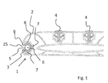
- Fig. 1 shows in a first embodiment, a sectional view of a line lamp 1 according to the invention.
- the line light 1 is designed in this embodiment as a footboard and includes a profile 2, which may be formed in particular of aluminum. It is a hollow chamber profile.
- Embedded in the profile 2 are, inter alia, also plastic footprints 4, which serve as step protection and reduce the risk of scratching of the adjacent profile 2.
- a light guide made of glass 5 is inserted in a form-fitting manner in a corresponding recess of the profile 2 on one side of the profile 2 by means of a mounting element 3. This can be inserted, for example.
- the optical waveguide 5 made of glass in this exemplary embodiment comprises a colored glass core 6, in particular made of white glass. Light is coupled out to the side via the opening 25 via the colored glass core 6.
- the mounting member 3 is formed as a plastic profile and includes positive locking elements 8, which sit in corresponding recesses 7 of the profile 2.
- the light guide 5 made of glass is set back from the adjacent profile 2, which protects it from damage.
- the light guide 5 made of glass directly forms the light exit surface, through which the light can be seen through the opening 25.
- the mounting member 3 further has wings 9, which protrude beyond the light guide 5 made of glass, which additionally protects it from damage.
- the opening angle of the line light is limited to a viewer. This is below 90 °.
- the trained as a plastic profile mounting member 3 is black.
- the line light looks similar to a recessed trim strip 4 made of plastic.
- the light guide 5 is arranged laterally in the installed state, since otherwise dirt could accumulate in the hopper, which is formed by the mounting member 3.
- Fig. 2 shows a perspective view of a line light 1, which is also designed as a running board.
- the flexible light guide 10 is terminated for this purpose at its ends, each with a sleeve 11, 12.
- a plug connection can be provided.
- the LED light source 13 is preferably formed watertight. About the cable 14, the LED light source 13 is powered.
- the light guide 5 can be arranged close to the side edge of the profile 2.
- the profile 2 is closed in the assembled state with the cap 15.
- the LED light source 13 In the cap 15 then the LED light source 13, and the flexible light guide 10 is arranged for connection. Consequently, only the light guide 5 can be seen.
- This embodiment of the invention allows a very simple, but robust and weatherproof design of a running board with a contour lighting, which is almost invisible in the unlit state.
- Fig. 3 shows, shown schematically, the optical fiber 5 used glass.
- This comprises a colored glass element 6, in particular made of white glass.
- the optical waveguide 5 comprises a cladding material 16, which has a lower refractive index than the core glass, so that a total reflection is achieved as a result.
- Fig. 4 is to be explained schematically the coupling of light into the light guide 5 made of glass.
- a fiber optic bundle 17 which is usually arranged in a tube (not shown).
- the hose is removed at the end of the bundle and the individual glass fibers of the glass fiber bundle 17 are filled into the sleeve 18, which has been previously filled with a transparent optical adhesive.
- a mandrel 19 which displaces the fiber in the field of Farbglasseele 6 the individual glass fibers when introducing the glass fiber bundle, so that little or no light is coupled directly into the Farbglasseele 6.
- Fig. 5 shows an alternative embodiment in which the optical fiber 5 is trimmed glass with the color glass 6 at the end.
- Light of the LED light source 13 is radiated from the side into the light guide 5 and deflected by a total reflection on the surface 21 and forwarded along the light guide 5.
- FIG. 6 Figure 4 shows schematically an alternative embodiment of the invention in which a flexible fiber optic cable 22 is used to emit light sideways.
- the fiber optic cable 22 is coupled via a sleeve 24 to an LED light source (not shown).
- the tube 23 of the glass fiber bundle is colored.
- the tube 23 is colored black and so appears black in the unlit state, so that it is difficult to distinguish from adjacent components.
- Fig. 7 shows in a schematic representation how an LED light source is also coupled directly to the end of a light guide 5 made of glass.
- the optical waveguide 5 made of glass in this exemplary embodiment consists of a glass rod with a colored glass core 6 (corresponding to the embodiment according to FIG Fig. 1 and Fig. 2 ).
- an LED lamp 28 is placed directly at the end of the light guide 5 here in this embodiment.
- the LED lamp 28 includes a housing 29.
- the housing 29 comprises a mask 32, by means of which the colored glass core 6 is shaded.
- the mask 32 may be, for example, a dark colored area in an otherwise transparent housing bottom.
- the masking also as a cover be provided, which is connected via webs with side walls of the housing.
- Fig. 8 shows a schematic representation of a vehicle door 26, in which a side emitting fiber optic cable 22 is used as Ambientebeleuchtung.
- the vehicle door 26 comprises on the inside a lining 27, for example made of a plastic.
- a groove is introduced, which defines the contour of the ambient lighting.
- the fiber optic cable 22 is clamped or glued.
- a fiber optic cable 22 with a dark colored tube is used.
- the adjacent panel 27 is black or dark gray.
- the fiber optic cable 22 is thus hardly recognizable, whereas in the dark a well visible and visually appealing ambient lighting is provided.
- an RGB light source can be used. This also makes it possible to change the ambient lighting in the light color.
- the tube is colored colorful.
- this is Embodiment of the invention, the adjacent cladding 27 formed in about the same color, which corresponds to the hose.
- an LED light source whose color matches the color of the tube, in particular an LED light source with only a single emission maximum, ie a light source which preferably emits in a narrow spectral range ,
- the rear side of the hose that is to say the side of the hose of the clamped or glued-in glass fiber cable 22 facing away from the observer, can be designed as a reflection surface.
- This can be realized by a coextruded reflective material, by a coating or by an inserted strip of a reflective material, for example a metal foil.
- the tube may be provided with axially outwardly extending projections which prevent twisting of the hose.
- Contour-sharp line lights could be provided by the invention, which are robust and weatherproof and are hardly recognizable at the same time in the unlit state.
Landscapes
- Engineering & Computer Science (AREA)
- Physics & Mathematics (AREA)
- Mechanical Engineering (AREA)
- Optics & Photonics (AREA)
- General Physics & Mathematics (AREA)
- General Engineering & Computer Science (AREA)
- Microelectronics & Electronic Packaging (AREA)
- Non-Portable Lighting Devices Or Systems Thereof (AREA)
- Light Guides In General And Applications Therefor (AREA)
- Arrangements Of Lighting Devices For Vehicle Interiors, Mounting And Supporting Thereof, Circuits Therefore (AREA)
- Optical Couplings Of Light Guides (AREA)
- Planar Illumination Modules (AREA)
Abstract
Description
- Die Erfindung betrifft eine seitenemittierende Linienleuchte. Insbesondere betrifft die Erfindung eine Linienleuchte welche als Konturenbeleuchtung für Fahrzeuge, insbesondere als Außenbeleuchtung, Verwendung findet. Im Speziellen betrifft die Erfindung ein Trittbrett mit einer Linienleuchte.
- Die erfindungsgemäße Linienleuchte kann aber auch für andere Anwendungen, insbesondere im Gebäude- und Möbelbereich Verwendung finden.
- Konturenbeleuchtungen finden insbesondere durch die Verbreitung der LED-Technik vermehrt Verwendung. Dies gilt unter anderem auch für den Fahrzeugbereich.
- Das Dokument
DE 20 2008 011 063 U1 (Schott AG) zeigt eine Beleuchtungsvorrichtung für Fahrzeuge, welche insbesondere als Trittbrettbeleuchtung vorgesehen ist. - Nachteilig an bekannten Konturbeleuchtungen für Fahrzeuge ist zumeist deren aufwendiger Einbau. So erfordert beispielsweise die in vorstehendem Dokument beschriebene Matte einen Einbau in ein Gehäuse. Dieses muss in der Regel auch noch wasser- und staubdicht ausgestaltet sein.
- Auch ist es schwierig, mit derartigen Systemen eine konturenscharfe, abgegrenzte linienförmige Leuchte bereit zustellen, welche bei Tageslicht kaum sichtbar ist.
- Der Erfindung liegt demgegenüber die Aufgabe zugrunde, eine Linienleuchte bereit zu stellen, welche robust ist und auf einfache Weise eingebaut werden kann.
- Weiter soll eine konturenscharfe Beleuchtung gewährleistet sein und im nicht-beleuchteten Zustand soll die erfindungsgemäße Linienleuchte möglichst wenig sichtbar sein.
- Die Aufgabe der Erfindung wird bereits durch eine Linienleuchte nach einem der unabhängigen Ansprüche gelöst.
- Bevorzugte Ausführungsformen und Weiterbildungen der Erfindung sind dem Gegenstand der jeweiligen Unteransprüche zu entnehmen.
- Die Erfindung betrifft eine Linienleuchte, also eine Leuchte bei welcher das Licht entlang einer Linie abgestrahlt wird. Diese Linie ist vorzugsweise gerade, kann aber auch gebogen sein.
- Die Linienleuchte umfasst einen seitenemittierenden transparenten Lichtleiter aus Glas.
- Vorzugsweise ist der seitenemittierende transparente Lichtleiter als Glasstab ausgebildet. Es handelt sich also um ein starres Bauelement. Vorzugsweise hat der Glasstab einen Durchmesser von 0,2 bis 10 mm, bevorzugt von 0,5 bis 5 mm und besonders bevorzugt von 2 bis 4 mm.
- Als derartiger Lichtleiter kann insbesondere ein Lichtleiter verwendet werden, wie er in der Offenlegungsschrift
DE 10 2012 208 810 A2 beschrieben ist. Ein derartiger Lichtleiter besteht aus einem Glasstab welcher eine Seele aus Farbglas, insbesondere eine Seele aus weißem Farbglas umfasst. Der Glasstab umfasst ein Hüllmaterial (cladding) mit einer niedrigeren Brechzahl als der Glasstab selbst, so dass es an den Wänden des Glasstabs zu Totalreflektionen kommt, was die Weiterleitung von Licht ermöglicht. Die in dem Glasstab befindliche Seele aus Farbglas wirkt als Streuzentrum und koppelt zur Seite hin Licht aus. Der Glasstab hat vorzugsweise den fünf bis zwanzigfachen Durchmesser wie die Seele aus Farbglas. So entsteht eine abgegrenzte, konturenscharfe Linie. - Die Seele aus Farbglas kann, muss aber nicht, genau in der Mitte des Glasstabs positioniert sein, sondern kann auch deaxial positioniert sein. Dies ermöglicht die gerichtete Auskopplung eines größeren Teils des Lichts zur Seite hin, da der Glasstab als Linse wirkt. Ein derartiger Glasstab kann beispielsweise hergestellt werden, indem ein Farbglasstäbchen mit mehreren Stäbchen aus transparentem Material gebündelt wird und hieraus im Ziehverfahren ein Glasstab gezogen wird. Durch die Positionierung des Farbglasstäbchens innerhalb der anderen Stäbchen wird die Position der Farbglasseele bestimmt.
- Es versteht sich, dass anstatt einer Farbglasseele auch ein Glas mit größeren Partikeln, die als Streuzentrum wirken, verwendet werden kann.
- Der seitenemittierende transparente Lichtleiter aus Glas wird formschlüssig mittels eines Montageelements in einem Profil gehalten.
- Es ist insbesondere vorgesehen, ein Montageelement aus einem Kunststoff, wie beispielsweise aus Gummi, zu verwenden und dieses in ein Profil, insbesondere ein Metallprofil, einzuschieben oder einzuclipsen.
- Vorzugsweise wird das Montageelement zusammen mit dem seitenemmitierenden transparenten Lichtleiter in das Profil eingezogen.
- Das Montageelement besteht vorzugsweise aus einem flexiblem Kunststoff wie beispielsweise Gummi oder Silikon, insbesondere mit einer Härte Shore A von weniger als 90, bevorzugt weniger als 80.
- Vorzugsweise umschließt das Montageelement den Lichtleiter um mindestens 270°. Der Öffnungswinkel der Linienleuchte zum Betrachter beträgt weniger als 90°, vorzugsweise liegt er zwischen 30 und 90°.
- Das Montageelement ist mithin vorzugsweise ebenfalls als Profil, insbesondere als Kunststoffprofil, ausgebildet.
- Das Montageelement und/oder das Profil weisen korrespondierende Formschlusselemente auf, mit welchen das Montageelement gesichert wird.
- Gleichzeitig hält das Montageelement formschlüssig den transparenten Lichtleiter aus Glas in Position.
- Vorzugsweise ist das Montageelement gegenüber dem Profil gegen Verdrehen gesichert, insbesondere mittel vorstehend beschriebener Formschlusselemente.
- Es hat sich gezeigt, dass ein derartiges System erstaunlich robust und wetterbeständig ist.
- Weiter ist ein derartiger transparenter Glasstab im nicht-beleuchteten Zustand unauffällig, da der Betrachter mit Ausnahme der Seele aus Farbglas durch den Stab hindurch schauen kann.
- Das Licht wird in den Glasstab an einer, vorzugsweise an beiden Seiten eingekoppelt, wobei sich die Lichtquelle vorzugsweise in einer Kappe befindet, welche auf das Profil aufgesetzt wird.
- Bei einer Weiterbildung der Erfindung ist auf einer Rückseite des Lichtleiters, also der dem Betrachter abgewandten Seite, das Montageelement und/oder das Profil dunkel.
- Insbesondere hat die hinter dem Lichtleiter aus Glas liegende Fläche im L*a*b*-Farbraum ein L*-Wert von unter 40, vorzugsweise von unter 30, besonders bevorzugt von unter 15.
- Die Fläche ist vorzugsweise schwarz oder dunkelgrau ausgebildet.
- Insbesondere unterscheidet sich der a*-Wert vom b*-Wert um maximal 10, vorzugsweise um maximal 5. Vorzugsweise liegen der a*- und der b*-Wert bei unter 20, vorzugsweise bei unter 10.
- Die Kombination eines dunklen Hintergrunds mit einem transparenten Glasstab ermöglicht eine fast unsichtbare Ausgestaltung der Linienleuchte bei im nicht-beleuchteten Zustand.
- Eine Außenseite des Glasstabs ist vorzugsweise unmittelbar außen an der Linienleuchte angeordnet. Das Licht wird mithin nicht durch eine Scheibe oder andere Bauelemente abgestrahlt. Dies ermöglicht eine einfache Ausgestaltung der Leuchte. Dennoch ist die erfindungsgemäße Linienleuchte wetterfest und robust. Der transparente Lichtleiter aus Glas liegt mithin von einer Betrachterseite aus gesehen vorzugsweise frei.
- Bei einer bevorzugten Ausführungsform ist der transparente Lichtleiter aus Glas gegenüber dem angrenzenden Profil rückversetzt, insbesondere um mindestens 0,5 mm, vorzugsweise um mindestens 1 mm.
- Der transparente Lichtleiter aus Glas ist mithin in das Profil eingelassen wodurch Beschädigungen des Glasstabs vermieden werden. Der Glasstab hat vorzugsweise einen Durchmesser von weniger als 10 mm, besonders bevorzugt von weniger als 5 mm. Ist der Lichtleiter aus Glas beispielsweise in ein Trittbrett eingebaut, so wird durch das angrenzende Profil ein Kontakt zum Beispiel mit dem Schuh des einsteigenden Fahrzeuginsassen vermieden.
- Weiter umfasst das Montageelement bei einer Ausführungsform der Erfindung seitlich über den Lichtleiter hinausragende Flügel, welche den Lichtleiter aus Glas ebenfalls vor mechanischem Kontakt schützen.
- Bei einer Ausführungsform der Erfindung ist der transparente Lichtleiter aus Glas über einen flexiblen Lichtleiter mit einer abgewinkelt angeordneten LED-Lichtquelle verbunden.
- Es ist insbesondere vorgesehen, als flexiblen Lichtleiter ein Glasfaserkabel zu verwenden. Dieses kann beispielsweise an beiden Enden mit einer Hülse terminiert sein. Auf einer Seite wird der Lichtleiter aus Glas und auf der anderen Seite wird die LED-Lichtquelle angeschlossen. Dies ermöglicht eine kompakte Ausgestaltung, bei welcher der Lichtleiter aus Glas nah an der Außenseite angeordnet sein kann, ohne dass die LED-Lichtquelle herausschaut. Insbesondere ist der Lichtleiter aus Glas weniger als 10 mm gegenüber dem angrenzenden Profil rückversetzt.
- Als LED-Lichtquelle kann beispielsweise eine fluiddichte LED-Lichtquelle verwendet werden.
- Alternativ oder in Kombination ist auch denkbar, den Lichtleiter aus Glas und/oder den flexiblen Lichtleiter gegenüber einem angrenzenden Gehäuse abzudichten, indem beispielsweise der Lichtleiter durch eine Dichtung geführt wird. Das Gehäuse kann beispielsweise auch als Kappe des Profils ausgebildet sein. In dem so geschaffenen fluiddichten Raum kann auch eine LED-Lichtquelle angeordnet sein, welche selbst nicht fluiddicht ist.
- Alternativ zu einem Anschluss über einen flexiblen Lichtleiter ist insbesondere vorgesehen, den Lichtleiter aus Glas randseitig schräg zu terminieren und das Licht über eine seitlich angeordnete LED-Lichtquelle einzustrahlen. Durch eine Totalreflektion an der schräg angeordneten Fläche wird das Licht in den Lichtleiter aus Glas eingekoppelt.
- Diese Ausführungsform ermöglicht eine noch kompaktere Ausgestaltung, ist allerdings mit dem Nachteil verbunden, dass es im Randbereich zu einer inhomogeneren Lichtintensitätsverteilung kommen kann.
- Die Erfindung betrifft des Weiteren eine Linienleuchte, insbesondere eine Linienleuchte, wie sie vorstehend beschrieben ist, welche also einen seitenemittierenden, transparenten Lichtleiter aus Glas umfasst.
- Der seitenemittierende transparente Lichtleiter aus Glas umfasst eine Farbglasseele zum seitlichen Einkoppeln von Licht. Mittels eines Glasfaserkabels, welches flexibel ist, ist der seitenemittierende transparente Lichtleiter an eine Lichtquelle, insbesondere an eine LED-Lichtquelle, angeschlossen.
- Das Farbglas der Farbglasseele besteht vorteilhaft aus einem Glas, in das Streuzentren eingelagert sind. Die Streuzentren des Farbglases werden in der Regel durch Phasentrennung und/oder Entmischung des Glases erzeugt. Beispielsweise kann das Farbglas ein Silikatglas sein, in das Streuzentren eingelagert sind, die einen erhöhten Gehalt an Läutermittel enthalten und die durch Phasentrennung und/oder Entmischung erzeugt wurden. Ein solches Glas kann als Farbglas kommerziell von verschiedenen Herstellern bezogen werden. Der erhältliche Glasstab mit einem Durchmesser von einigen Millimetern wird üblicherweise für die Herstellung der Farbglasseele zu einer typischen Dicke von zwischen etwa 100 µm und 1 mm wie zuvor beschrieben ausgezogen.
- Das Glasfaserkabel ist vorzugsweise zumindest gegenüber dem seitenemittierenden Lichtleiter mittels einer Hülse terminiert.
- Insbesondere wird eine vorzugsweise topfförmige Hülse aus einem transparenten Kunststoff verwendet. Das Glasfaserkabel ist in der Regel eingeschlaucht. Es handelt sich also um ein Bündel aus Glasfasern. Diese bestehen jeweils aus einem Kernglas, welches mit einem Material niedrigerer Brechzahl (cladding) umhüllt ist, um Totalreflektionen zu erreichen.
- Zum Terminieren des Glasfaserbündels kann dessen Ende mit, vorzugweise aber ohne Schlauch in die Hülse eingeführt werden und dort mittels eines eingefüllten Klebstoffs befestigt werden. Insbesondere kann ein transparenter UVhärtender Klebstoff verwendet werden.
- Um zu vermeiden, dass randseitig direkt in die Farbglasseele Licht eingekoppelt wird, umfasst ein Boden der Hülse gegenüber der Farbglasseele einen nach innen ragenden Dorn oder ist abgedeckt, insbesondere eingefärbt.
- Vorzugsweise umfasst der Boden gegenüber der Farbglasseele einen Dorn, welcher im Bereich der Farbglasseele die einzelnen Glasfasern des Glasfaserkabels verdrängt, so dass im Bereich der Farbglasseele weniger oder kein Licht eingekoppelt wird.
- Alternativ ist aber auch denkbar, den Bereich gegenüber der Farbglasseele einfach abzudecken beziehungsweise einzufärben. Diese Ausführungsvariante hat allerdings den Nachteil, dass das in diesem Bereich durch das Glasfaserkabel geführte Licht überwiegend verloren geht. Die Erfindung betrifft des Weiteren eine Linienleuchte, insbesondere wie vorstehend beschrieben, welchen einen seitenemittierenden, transparenten Lichtleiter aus Glas umfasst, der zumindest eine Farbglasseele zum Auskoppeln von Licht aufweist. In zumindest ein Ende des seitenemittierenden Lichtleiters wird Licht eingekoppelt.
- Vorzugsweise wird das Licht mittels einer direkt an das Ende des seitenemittierenden Lichtleiters angrenzenden Lichtquelle, insbesondere eine LED-Lichtquelle, eingekoppelt.
- Gemäß der Erfindung ist das Ende des seitenemittierenden Lichtleiters im Bereich der Farbglasseele maskiert.
- Die Farbglasseele ist also, wie bereits vorstehend ausgeführt, abgedeckt, wodurch im Bereich der Farbglasseele kein Licht oder weniger Licht in den Lichtleiter eingekoppelt wird, was Inhomogenitäten verringert.
- Die Maskierung kann sowohl auf der Seite der Lichtquelle, insbesondere an einem Gehäuse der Lichtquelle, angeordnet sein.
- So kann beispielsweise ein Gehäuse mit einem transparenten Boden verwendet werden, welcher im Bereich der Farbglasseele lichtundurchlässig ausgebildet ist.
- Weiter kann das Gehäuse im Bereich der Farbglasseele eine lichtundurchlässige Abdeckung umfassen, welche beispielsweise mittels zumindest eines Stegs mit einer Seitenwand des Gehäuses verbunden ist.
- Bei einer anderen Ausführungsform der Erfindung ist der seitenemittierende Lichtleiter selbst im Bereich der Farbglasseele maskiert.
- Neben einer Hülse mit einem lichtundurchlässigen Fleck ist dies beispielsweise durch eine Beschichtung des Endes des seitenemittierenden Lichtleiters im Bereich der Farbglasseele möglich.
- Die Erfindung betrifft des Weiteren eine Linienleuchte, welche ein seitenemittierendes Glasfaserkabel umfasst, welches in einem Schlauch angeordnet ist.
- Ein derartiges seitenemittierendes Glasfaserkabel ist beispielsweise in der
WO 2009/100834 A2 gezeigt. Ein Glasfaserkabel hat gegenüber der ersten Ausführungsvariante der Erfindung den Vorteil, dass es flexibel ist. - Gemäß der Erfindung ist der Schlauch dunkel eingefärbt, insbesondere hatte dieser im sichtbaren Bereich des Lichts eine mittlere Transmission von weniger als 40 %, vorzugsweise von weniger als 30 %.
- Diese Ausführungsvariante geht mithin einen anderen Weg, um im nicht-beleuchteten Zustand eine nahezu unsichtbare Ausgestaltung der Linienleuchte zu ermöglichen.
- Statt eines dunklen Hintergrundes ist der Schlauch, mit welchem das Glasfaserkabel ummantelt ist, derart eingefärbt, dass dieser im nicht-beleuchteten Zustand nahezu schwarz erscheint und damit nahezu unsichtbar ist.
- Insbesondere hat das Material des Schlauchs im L*a*b-Farbraum ein L*-Wert von unter 40, vorzugsweise von unter 30 und besonders bevorzugt von unter 15.
- Der a*- und der b*-Wert liegt vorzugsweise bei unter 20, besonders bevorzugt bei unter 10.
- Der schwarze Mantel kann auch einem Kunststoff, insbesondere einem Polyethylen, Polypropylen oder aus einem Silikon oder aus PVC bestehen. Die Schwarzfärbung kann beispielsweise durch Einmischen von Rußpartikeln erzielt werden.
- Bei einer anderen Ausführungsvariante der Erfindung, insbesondere bei welcher eine angrenzende Aufnahme nicht schwarz ist, ist der Schlauch in einer Farbe eingefärbt, welcher der Farbe einer angrenzenden Aufnahme oder eines angrenzenden Verkleidungsteils entspricht.
- Der Schlauch kann beispielsweise in ein Profil aber auch in eine Verkleidung, beispielsweise eine Wand-, Türen- oder Deckenverkleidung eines Fahrzeugs oder Gebäudes eingelassen sein, welche eine bestimmte Farbe hat.
- Der Schlauch hat wiederum vorzugsweise im sichtbaren Bereich eine mittlere Transmission von weniger als 40 %, vorzugsweise von weniger als 30 %.
- Über eine Einfärbung, welche der Farbe der angrenzenden Aufnahme entspricht, wird eine nahezu unsichtbare Integration des Glasfaserkabels ermöglicht.
- Insbesondere unterscheidet sich der a*- und/oder der b*-Wert im L*a*b*-Farbraum von angrenzender Aufnahme bzw. angrenzendem Verkleidungsteil und Schlauch um weniger als 10, vorzugsweise weniger als 5.
- Neben einer bunten oder schwarzen Einfärbung ist gemäß einer Ausführungsform der Erfindung vorgesehen, den Schlauch in einer von Schwarz verschiedenen unbunten Farbe einzufärben, insbesondere silbern. Hierzu können zum Bespiel Aluminiumoxidpartikel verwendet werden.
- Insbesondere können Pigmentpartikel mit einer mittleren Partikelgröße von 5 nm bis 10 µm, bevorzugt von 0,1 µm bis 10 µm, ganz besonders bevorzugt von 0,5 µm bis 5 µm verwendet werden.
- Zum Einfärben werden gemäß einer Ausführungsform anorganische Farbmittel verwendet, welche als Farbkonzentrate dem Material des Schlauchs zugesetzt werden können.
- Diese können zwischen 2 bis 60% Pigmentanteil umfassen, die mit dem Trägermaterial gemischt sind.
- Das Trägermaterial kann beispielsweise ein Polyethylen, insbesondere LLDPE (Linear Low Density Polyethylene), ein Polypropylen oder ein thermoplastisches Polyurethan sein.
- Das Farbkonzentrat (sog. Masterbatch) wird in einer Menge von 0,1 - 20 %, vorzugsweise von 1 bis 10 % (Gewichts%) am Extruder beigemischt.
- Als Pigmente können sowohl sphärische Pigmente als auch rundlich bis flache Pigmente, insbesondere plättchenförmige Pigmente, verwendet werden, die wie kleine Spiegel wirken.
- Das Erscheinungsbild der späteren Anwendung ist in hohem Maße von den Pigmenten abhängig. Hiervon ist besonders die Homogenität (Abstrahleffekt) betroffen.
- Durch flächige Pigmente kann beim Durchscheinen des Schlauchs ein besonderer Effekt hervorrufen werden.
- Je nach Blickrichtung auf den Schlauch erscheint dieser durch die Ausrichtung der Spiegelflächen der Pigmente dunkler oder heller.
- Bei einer weiteren Ausführungsform wird eine Strukturierung im Kabelmantel durch die Anordnung und Verteilung der Pigmente erzeugt.
- Bei einer Weiterbildung der Erfindung werden bei Extrusion des Schlauchs zumindest zwei verschiedene Materialien coextrudiert. Der Schlauch besteht so aus zumindest zwei verschiedenen Materialien.
- Insbesondere kann ein Teil des Mantels aus einem reflektierenden Kunststoff ausgebildet werden, welcher später die Rückseite des eingesetzten Schlauchs bildet.
- Eine Reflexion kann auch eine Lackierung oder ein Bekleben mit Folie erreicht werden.
- Im Fall eines dunklen, vorzugsweise schwarzen, Schlauchs, hat bei einer bevorzugten Ausführungsform der Erfindung im L*a*b*-Farbraum der Schlauch ein L*-Wert von unter 40, vorzugsweise von unter 30 und besonders bevorzugt von unter 15.
- Ansonsten kann das Glasfaserkabel auf ähnliche Weise eingebaut werden wie der zuvor beschriebene Lichtleiter aus transparentem Glas.
- Insbesondere ist denkbar, den Schlauch mittels zumindest eines Montageelements formschlüssig in ein Profil einzuclipsen oder einzuschieben.
- Vorzugsweise ist auch das Glasfaserkabel gegenüber dem angrenzenden Profil rückversetzt, insbesondere um zumindest 0,5 mm, vorzugsweise um zumindest 1 mm.
- Vorzugsweise hat auch das Glasfaserkabel einen Durchmesser von 0,2 bis 10 mm, bevorzugt von 0,5 bis 5 mm und besonders bevorzugt von 2 bis 4 mm.
- Die erfindungsgemäße Linienleuchte findet insbesondere in Fahrzeugen Verwendung. Dabei ist auch denkbar, das Licht einer RGB-Lichtquelle einzukoppeln, so dass die Lichtfarbe verändert werden kann.
- Die Erfindung betrifft des Weiteren eine Linienleuchte, insbesondere eine Linienleuchte, wie sie zuvor beschrieben wurde, welche ein seitenemittierendes Glasfaserkabel umfasst, das in einem Schlauch angeordnet ist. Gemäß der Erfindung ist der Schlauch bunt eingefärbt.
- Es handelt sich bei dieser Ausführungsform der Erfindung also um eine Einfärbung des Schlauchs mit bunten Farbpartikeln.
- Insbesondere hat das Material des Schlauchs im L*a*b*-Farbraum eine Buntheit C* ab von >10, vorzugsweise von >25 und besonders bevorzugt von >30. Die Buntheit C*ab ist definiert als die Wurzel der Summe der Quadratzahlen von a* und b*.
- Bei dieser Ausführungsform der Erfindung, also der Ausführungsform mit einem bunten Schlauch, umfasst die Linienleuchte vorzugsweise eine Lichtquelle, insbesondere eine LED-Lichtquelle, deren Wellenlänge an die Farbe des Schlauchs angepasst ist.
- Es hat sich herausgestellt, dass im Unterschied zu einer unbunten Einfärbung des Schlauchs die Verwendung beispielsweise eine Weißlicht-Lichtquelle zu unerwünschten Verfärbungen im Randbereich des Schlauchs führt.
- Vorzugsweise wird eine Lichtquelle verwendet, die eine dominante Wellenlänge emittiert, die sich maximal 30 nm, vorzugsweise maximal 20 nm, von der Wellenlänge unterscheidet, die der Farbe des Schlauchs entspricht.
- Die Lichtquelle emittiert also in etwa in derselben Wellenlänge, welche der Farbe des Schlauchs entspricht.
- Vorzugsweise wird eine Lichtquelle verwendet, welche genau ein Emissionsmaximum hat. Es wird also vorzugsweise keine Lichtquelle verwendet, deren Farbe sich aus zwei oder mehr Wellenlängen maximal zusammensetzt.
- Es wird insbesondere eine Lichtquelle verwendet, die ein Emissionsmaximum hat, das im Spektrum der Lichtquelle eine Standardabweichung hat, bei welcher σ in einem Intervall von maximal +/- 50 nm, vorzugsweise von maximal +/-25 nm, liegt.
- Es wird also vorzugsweise eine Lichtquelle verwendet, die in einem engen Spektrum abstrahlt. Insbesondere kann auch eine LED-Lichtquelle verwendet werden, welche im Wesentlichen monochromatisch abstrahlt.
- So kann erreicht werden, dass auch bei Verwendung eines bunt eingefärbten Schlauchs die Linienleuchte Licht mit einem sehr einheitlichen Farbeindruck emittiert.
- Wegen der Robustheit kann die Linienleuchte insbesondere im Außenbereich verwendet werden. Aber auch eine Verwendung als Konturenbeleuchtung im Innenraum ist denkbar. Dies gilt im Besonderen für die Ausführungsvariante als seitenemittierendes Glasfaserkabel. Dieses kann beispielsweise in der Innenverkleidung derart eingesetzt werden, dass es wie eine Übergangsnaht einer Bespannung aus beispielsweise Stoff oder Leder aussieht. Im eingeschalteten Zustand ergibt sich eine konturenscharfe Beleuchtung, wohingegen im nicht-beleuchteten Zustand die Linienleuchte nahezu unsichtbar ist.
- Weitere Anwendungsmöglichkeiten sind beispielsweise aber auch medizinische Geräte, insbesondere Konturenbeleuchtungen von Behandlungsstühlen, Operationssälen, Tomographen, Röntgengeräten, etc.
- Weiter können, insbesondere als Außenbeleuchtung, Linienleuchten mit einer Länge von über 1 m, vorzugsweise von über 3 m bereit gestellt werden. Hierdurch kann beispielsweise auch eine Konturbeleuchtung für LKWs bereit gestellt werden.
- Denkbar ist auch eine Verwendung als Gangbeleuchtung eines Flugzeugs oder Schiffs, als eine beleuchtete Fensterkontur, als eine Konturenbeleuchtung im Küchenbereich oder bei einem Möbelstück. Weiter können beispielsweise Bedienelemente oder Sitze beleuchtet werden. Denkbar sind auch Schaltschränke, Spielekonsolen, Öfen, Kamine, Möbel und Designelemente an Leuchten selbst.
- Schließlich ist auch denkbar Funktions- oder Statusanzeigen als Linienleuchte auszugestalten. Weiter ist denkbar die Nachtbeleuchtung in einem Fahrzeugcockpit teilweise aus erfindungsgemäßen Linienleuchten auszubilden.
- Die Erfindung betrifft des Weiteren eine Tür, Wand- oder Deckenverkleidung eines Fahrzeugs, welche eine vorstehend beschriebene Linienleuchte mit einem in einen Schlauch eingebrachten Glasfaserbündel umfasst.
- Vorzugsweise ist der Schlauch in eine Nut eingeklemmt oder eingeklebt.
- Es ist insbesondere vorgesehen, dass ein eingefärbter, insbesondere bunt eingefärbter, Schlauch im ausgeschalteten Zustand der Linienleuchte an die Farbe des angrenzenden Verkleidungsteils angepasst ist.
- Im eingeschalteten Zustand wird gemäß einer Ausführungsform Licht derselben Farbe emittiert.
- Bei einer anderen Ausführungsform, für welche vorzugsweise ein unbunt, insbesondere schwarz oder silbern, eingefärbter Schlauch verwendet wird, emittiert die Linienleuchte Licht einer anderen Farbe und die Linienleuchte tritt mit dem Einschalten optisch hervor.
- Der Gegenstand der Erfindung soll im Folgenden bezugnehmend auf die Zeichnungen
Fig. 1 bis Fig. 8 näher erläutert werden. - Fig. 1
- zeigt eine Schnittansicht einer ersten Ausführungsform einer erfindungsgemäßen Linienleuchte.
- Fig. 2
- zeigt ein Ausführungsbeispiel in einer perspektivischen Ansicht.
- Fig. 3
- Bezugnehmend auf
Fig. 3 soll die Ausführungsvariante mit einem transparenten Lichtleiter aus Glas näher erläutert werden. - Fig. 4
- Bezugnehmend auf
Fig. 4 soll die Ankopplung des Lichtes an den transparenten Lichtleiter aus Glas erläutert werden - Fig. 5
- zeigt eine alternative Ausführungsform einer Einkopplung von Licht.
- Fig. 6
- Bezugnehmend auf
Fig. 6 soll die alternative Ausführungsform der Erfindung erläutert werden, bei welcher ein Glasfaserkabel, das flexibel ist, verwendet wird. - Fig. 7
- zeigt in einer schematischen Darstellung, wie eine LED-Lichtquelle direkt an einen Lichtleiter aus Glas angekoppelt ist.
- Fig. 8
- ist eine schematische Darstellung einer mit einer Verkleidung versehenen Fahrzeugtür, in welche ein seitenemittierendes Glasfaserkabel eingesetzt ist.
-
Fig. 1 zeigt in einer ersten Ausführungsform eine Schnittansicht einer erfindungsgemäßen Linienleuchte 1. - Die Linienleuchte 1 ist in diesem Ausführungsbeispiel als Trittbrett ausgestaltet und umfasst ein Profil 2, welches insbesondere aus Aluminium ausgebildet sein kann. Es handelt sich um ein Hohlkammerprofil.
- In das Profil 2 eingelassen sind unter anderem auch Trittleisten 4 aus Kunststoff, welche als Trittschutz dienen und die Gefahr des Verkratzens des angrenzenden Profils 2 reduzieren.
- Um eine Linienleuchte bereit zu stellen, ist an einer Seite des Profils 2 ein Lichtleiter aus Glas 5 mittels eines Montageelements 3 formschlüssig in einer entsprechenden Aussparung des Profils 2 eingelassen. Dieser kann beispielsweise eingeschoben werden.
- Der Lichtleiter 5 aus Glas umfasst in diesem Ausführungsbeispiel eine Farbglasseele 6, insbesondere aus Weißglas. Über die Farbglasseele 6 wird Licht zur Seite hin über die Öffnung 25 ausgekoppelt.
- Das Montageelement 3 ist als Kunststoffprofil ausgebildet und umfasst Formschlusselemente 8, welche in korrespondierenden Aussparungen 7 des Profils 2 sitzen.
- Der Lichtleiter 5 aus Glas ist gegenüber dem angrenzenden Profil 2 rückversetzt, was diesen vor Beschädigungen schützt.
- Ansonsten bildet der Lichtleiter 5 aus Glas unmittelbar die Lichtaustrittsfläche, durch welche das Licht durch die Öffnung 25 zu sehen ist.
- Das Montageelement 3 hat des Weiteren noch Flügel 9, welche über den Lichtleiter 5 aus Glas hinausragen, was diesen zusätzlich vor Beschädigungen schützt.
- Durch das Montageelement 3, welches den Lichtleiter 5 um zumindest 270° umschließt wird der Öffnungswinkel der Linienleuchte gegenüber einem Betrachter begrenzt. Dieser liegt bei unter 90°.
- In diesem Ausführungsbeispiel ist das als Kunststoffprofil ausgebildete Montageelement 3 schwarz.
- Aufgrund der transparenten Ausgestaltung des Lichtleiters 5 sieht der Betrachter im nicht-beleuchten Zustand das schwarze dahinterliegende Montagelement 3, so dass der Lichtleiter 5 im nicht-beleuchteten Zustand nahezu unsichtbar ist.
- Die Linienleuchte sieht vielmehr einer eingelassenen Trittleiste 4 aus Kunststoff ähnlich.
- Es versteht sich, dass bei dieser Ausführungsform der Erfindung, welche ein Trittbrett betrifft, der Lichtleiter 5 im eingebauten Zustand seitlich angeordnet ist, da sich ansonsten Schmutz in dem Trichter ansammeln könnte, welcher durch das Montageelement 3 gebildet wird.
- Für einen Einbau auf der Oberseite ist denkbar, den Trichter der durch die Öffnung 25 gebildet wird, durch ein transparentes Kunststoffbauteil zu verschließen (nicht dargestellt).
-
Fig. 2 zeigt in einer perspektivischen Ansicht eine Linienleuchte 1, welche ebenfalls als Trittbrett ausgebildet ist. - Zu erkennen ist das Profil 2 aus Metall, in welches die Trittleisten 4 eingelassen sind.
- Der über das Montageelement 3 formschlüssig mit dem Profil 2 verbundene Lichtleiter 5 ist über einen flexiblen Lichtleiter 10 mit einer LED-Lichtquelle 13 verbunden.
- Der flexible Lichtleiter 10 ist hierzu an seinen Enden mit jeweils einer Hülse 11, 12 terminiert. So kann beispielweise eine Steckverbindung bereit gestellt werden.
- Die LED-Lichtquelle 13 ist vorzugsweise wasserdicht ausgebildet. Über die Kabel 14 wird die LED-Lichtquelle 13 mit Strom versorgt.
- Da die LED-Lichtquelle 13 abgewinkelt eingesetzt werden kann, kann der Lichtleiter 5 nah am Seitenrand des Profils 2 angeordnet sein.
- Das Profil 2 wird im fertig montierten Zustand mit der Kappe 15 verschlossen. In der Kappe 15 ist sodann die LED-Lichtquelle 13, sowie der flexible Lichtleiter 10 zur Verbindung angeordnet. Zu sehen ist mithin nur der Lichtleiter 5.
- Diese Ausführungsvariante der Erfindung ermöglicht eine sehr einfache, aber robuste und wetterfeste Ausgestaltung eines Trittbretts mit einer Konturbeleuchtung, welche im unbeleuchteten Zustand nahezu unsichtbar ist.
-
Fig. 3 zeigt, schematisch dargestellt, den verwendeten Lichtleiter 5 aus Glas. - Dieser umfasst eine Farbglasseele 6, insbesondere aus Weißglas.
- Weiter umfasst der Lichtleiter 5 ein Hüllmaterial 16, welches eine niedrigere Brechzahl als das Kernglas aufweist, so dass hierdurch eine Totalreflektion erreicht wird.
- Über die Farbglasseele 6 wird Licht zur Seite hin ausgekoppelt, indem die Farbglasseele 6 als Streuzentrum wirkt.
- Bezugnehmend auf
Fig. 4 soll schematisch die Einkopplung von Licht in den Lichtleiter 5 aus Glas erläutert werden. - Es wird als flexibler Lichtleiter ein Glasfaserbündel 17 verwendet, welches in der Regel in einem Schlauch (nicht dargestellt) angeordnet ist.
- Zum Terminieren des Faserbündels 17 wird am Ende des Bündels der Schlauch entfernt und die einzelnen Glasfasern des Glasfaserbündels 17 werden in die Hülse 18 eingefüllt, welche zuvor mit einem transparenten optischen Klebstoff befüllt wurde.
- Aus dem Boden 20 der Hülse steht gegenüber der Farbglasseele 6 ein Dorn 19 hervor, welcher beim Einbringen des Glasfaserbündels die Faser im Bereich der Farbglasseele 6 die einzelnen Glasfasern verdrängt, so dass kein oder nur wenig Licht direkt in die Farbglasseele 6 eingekoppelt wird.
- Auf diese Weise wird eine inhomogene Abstrahlung im Randbereich vermieden.
- Es versteht sich, dass weitere Kopplungselemente zum Koppeln von Hülse 18 und Lichtleiter 5 in dieser schematischen Zeichnung nicht dargestellt sind. Dies betrifft insbesondere Formschluss- oder Klemmelemente.
-
Fig. 5 zeigt eine alternative Ausführungsform, bei welcher der Lichtleiter 5 aus Glas mit der Farbglasseele 6 am Ende abgeschrägt ist. Licht der LED-Lichtquelle 13 wird von der Seite in den Lichtleiter 5 eingestrahlt und über eine Totalreflektion an der Fläche 21 umgelenkt und entlang des Lichtleiters 5 weitergeleitet. - Diese Ausführungsvariante ermöglicht gegenüber der in
Fig. 2 dargestellten Ausführungsvariante eine noch kompaktere Ausgestaltung, geht aber in der Regel mit höheren Lichtverlusten und einer inhomogeneren Ausleuchtung im Randbereich einher. -
Fig. 6 zeigt, schematisch dargestellt, eine alternative Ausführungsform der Erfindung, bei welcher ein flexibles Glasfaserkabel 22 verwendet wird, um Licht zur Seite hin auszustrahlen. - Das Glasfaserkabel 22 ist über eine Hülse 24 an eine LED-Lichtquelle (nicht dargestellt) angekoppelt.
- Der Schlauch 23 des Glasfaserbündels ist eingefärbt.
- In einer Ausführungsform der Erfindung ist der Schlauch 23 schwarz eingefärbt und erscheint so im unbeleuchteten Zustand schwarz, so dass er kaum von angrenzenden Bauelementen zu unterscheiden ist.
- Denkbar ist aber auch eine andersfarbige Einfärbung, welche in etwa die gleiche Farbe hat wie eine angrenzende Aufnahme, insbesondere ein angrenzendes Verkleidungsteil.
-
Fig. 7 zeigt in einer schematischen Darstellung, wie eine LED-Lichtquelle auch direkt an das Ende eines Lichtleiters 5 aus Glas angekoppelt ist. - Der Lichtleiter 5 aus Glas besteht in diesem Ausführungsbeispiel aus einem Glasstab mit einer Farbglasseele 6 (entsprechend der Ausführungsform gemäß
Fig. 1 undFig. 2 ). - Im Unterschied zu der in
Fig. 1 undFig. 2 dargestellten Ausführungsform wird hier in diesem Ausführungsbeispiel eine LED-Leuchte 28 direkt an das Ende des Lichtleiters 5 gesetzt. - Die LED-Leuchte 28 umfasst ein Gehäuse 29.
- In dem Gehäuse 29 ist eine Platine 30 mit einer LED_31, in diesem Ausführungsbeispiel ausgebildet als Dünnschicht-LED, angeordnet.
- Gegenüber der Farbglasseele 6 umfasst das Gehäuse 29 eine Maskierung 32, durch welche die Farbglasseele 6 abgeschattet wird.
- Hierdurch werden ebenfalls Inhomogenitäten in der Nähe der Einkoppelstelle reduziert.
- Die Maskierung 32 kann beispielsweise ein dunkel eingefärbter Bereich in einem sonst transparenten Gehäuseboden sein. Im Falle eines unten offenen Gehäuses (nicht dargestellt) kann die Maskierung auch als Abdeckung bereitgestellt werden, welche über Stege mit Seitenwänden des Gehäuses verbunden ist.
-
Fig. 8 zeigt in einer schematischen Darstellung eine Fahrzeugtür 26, in welche als Ambientebeleuchtung ein seitenemittierendes Glasfaserkabel 22 eingesetzt ist. - Die Fahrzeugtür 26 umfasst hierfür innenseitig eine Verkleidung 27, beispielsweise aus einem Kunststoff. In die Verkleidung 27 ist eine Nut eingebracht, welche die Kontur der Ambientebeleuchtung vorgibt.
- In diese Nut wird das Glasfaserkabel 22 eingeklemmt oder eingeklebt.
- In einer Ausführungsform wird ein Glasfaserkabel 22 mit einem dunkel eingefärbten Schlauch verwendet. Vorzugsweise ist bei dieser Ausführungsform der Erfindung auch die angrenzende Verkleidung 27 schwarz oder dunkelgrau.
- Im unbeleuchteten Zustand ist das Glasfaserkabel 22 so kaum zu erkennen, wohingegen bei Dunkelheit eine gut sichtbare und optisch ansprechende Ambientebeleuchtung bereitgestellt wird.
- Bei Verwendung eines unbunt eingefärbten Schlauchs kann insbesondere auch eine RGB-Lichtquelle verwendet werden. Dies ermöglicht es auch, die Ambientebeleuchtung in der Lichtfarbe verändern zu können.
- Bei einer anderen Ausführungsform der Erfindung ist der Schlauch bunt eingefärbt. Vorzugsweise ist bei dieser Ausführungsform der Erfindung auch die angrenzende Verkleidung 27 in etwa der gleichen Farbe ausgebildet, die dem Schlauch entspricht.
- Es hat sich herausgestellt, dass bei dieser Ausführungsform der Erfindung lieber einer LED-Lichtquelle verwendet wird, deren Farbe der Farbe des Schlauchs angepasst ist, insbesondere eine LED-Lichtquelle mit lediglich einem einzigen Emissionsmaximum, also eine Lichtquelle, die vorzugsweise in einem engen Spektralbereich emittiert.
- So lässt sich auch mit einem bunt eingefärbten Schlauch eine Ambientebeleuchtung mit homogenem Farbeindruck bereitstellen.
- Bei allen Ausführungsformen kann die Rückseite des Schlauchs, also die dem Betrachter abgewandte Seite des Schlauchs des eingeklemmten oder eingeklebten Glasfaserkabels 22, als Reflexionsfläche ausgebildet sein. Dies kann durch ein coextrudiertes reflektierendes Material, durch eine Lackierung oder durch einen eingelegten Streifen eines reflektierenden Materials, beispielsweise eine Metallfolie, realisiert sein.
- Bei dieser Ausführungsform der Erfindung ist es vorteilhaft, den Schlauch außen nicht genau kreisrund auszugestalten, um ein orientiertes Einbringen des Glasfaserkabels 22 in die Nut zu erleichern. Insbesondere kann der Schlauch mit sich axial nach außen erstreckenden Vorsprüngen versehen sein, die eine Verdrehung des Schlauchs verhindern.
- Durch die Erfindung konnten konturenscharfe Linienleuchten bereit gestellt werden, welche robust und wetterfest sind und gleichzeitig im unbeleuchteten Zustand kaum zu erkennen sind.
-
- 1
- Linienleuchte
- 2
- Profil
- 3
- Montageelement
- 4
- Trittleiste
- 5
- Lichtleiter aus Glas
- 6
- Farbglasseele
- 7
- Aussparung
- 8
- Formschlusselement
- 9
- Flügel
- 10
- flexibler Lichtleiter
- 11
- Hülse
- 12
- Hülse
- 13
- LED-Lichtquelle
- 14
- Kabel
- 15
- Kappe
- 16
- Hüllmaterial
- 17
- Glasfaserbündel
- 18
- Hülse
- 19
- Dorn
- 20
- Boden
- 21
- Fläche
- 22
- Glasfaserkabel
- 23
- Schlauch
- 24
- Hülse
- 25
- Öffnung
- 26
- Fahrzeugtür
- 27
- Verkleidung
- 28
- LED-Leuchte
- 29
- Gehäuse
- 30
- Platine
- 31
- LED
- 32
- Maskierung
Claims (15)
- Linienleuchte, umfassend einen seitenemittierenden transparenten Lichtleiter aus Glas, welcher formschlüssig mittels eines Montageelements in einem Profil gehalten ist.
- Linienleuchte nach dem vorstehenden Anspruch, dadurch gekennzeichnet, dass das Montageelement und/oder das Profil korrespondierende Formschlusselemente aufweisen, mit welchen das Montageelement gesichert wird.
- Linienleuchte nach einem der vorstehenden Ansprüche, dadurch gekennzeichnet, dass das Montagelement seitlich über den Lichtleiter hinausragende Flügel aufweist.
- Linienleuchte nach einem der vorstehenden Ansprüche, dadurch gekennzeichnet, dass das Montagelement gegenüber dem Profil gegen Verdrehen gesichert ist.
- Linienleuchte nach einem der vorstehenden Ansprüche, dadurch gekennzeichnet, dass der Öffnungswinkel der Linienleuchte gegenüber einem Betrachter durch das Montagelement begrenzt wird, wobei der Öffnungswinkel weniger als 90° beträgt.
- Linienleuchte nach einem der vorstehenden Ansprüche, dadurch gekennzeichnet, dass auf einer Rückseite des Lichtleiters das Montageelement und/oder das Profil dunkel ist, insbesondere im L*a*b*-Farbraum einen L*-Wert von unter 40, vorzugsweise von unter 30, besonders bevorzugt von unter 15 hat.
- Linienleuchte nach einem der vorstehenden Ansprüche, dadurch gekennzeichnet, dass der transparente Lichtleiter aus Glas gegenüber dem angrenzenden Profil rückversetzt ist, insbesondere um mindestens 0,5 mm, vorzugsweise um mindestens 1 mm.
- Linienleuchte nach einem der vorstehenden Ansprüche, dadurch gekennzeichnet, dass der transparente Lichtleiter aus Glas von einer Betrachterseite aus gesehen frei liegt.
- Linienleuchte nach einem der vorstehenden Ansprüche, dadurch gekennzeichnet, dass der transparente Lichtleiter aus Glas über einen flexiblen Lichtleiter mit einer abgewinkelt gegenüber dem transparenten Lichtleiterangeordneten LED-Lichtquelle verbunden ist.
- Linienleuchte nach dem vorstehenden Anspruch, dadurch gekennzeichnet, dass der flexible Lichtleiter und die LED-Lichtquelle in einer auf das Profil aufgesetzten Kappe angeordnet sind.
- Linienleuchte, insbesondere Linienleuchte nach einem der vorstehenden Ansprüche, umfassend einen seitenemittierenden transparenten Lichtleiter aus Glas, welcher zumindest eine Farbglasseele zum seitlichen Auskoppeln von Licht umfasst, wobei der seitenemittierende transparente Lichtleiter mittels eines Glasfaserkabels an eine Lichtquelle angeschlossen ist, welches zumindest gegenüber dem seitenemittierenden Lichtleiter mittels einer Kappe terminiert ist, wobei die der Boden der Kappe gegenüber der Farbglasseele einen nach innen ragenden Dorn umfasst oder abgedeckt ist.
- Linienleuchte, insbesondere Linienleuchte nach einem der vorstehenden Ansprüche, umfassend einen seitenemittierenden transparenten Lichtleiter aus Glas, welcher zumindest eine Farbglasseele zum seitlichen Auskoppeln von Licht umfasst, und wobei in zumindest ein Ende des seitenemittierenden Lichtleiters Licht eingekoppelt wird, vorzugsweise mittels einer direkt an das Ende des seitenemittierenden Lichtleiters angrenzenden Lichtquelle, dadurch gekennzeichnet, dass das Ende des seitenemittierenden Lichtleiters im Bereich der Farbglasseele maskiert ist.
- Linienleuchte, umfassend ein seitenemittierendes Glasfaserkabel, wobei das Glasfaserkabel in einem Schlauch angeordnet ist, wobei der Schlauch dunkel eingefärbt ist, insbesondere im sichtbaren Bereich des Lichts eine mittlere Transmission von weniger als 40 %, vorzugsweise von weniger als 30 % aufweist.
- Linienleuchte, umfassend ein seitenemittierendes Glasfaserkabel, wobei das Glasfaserkabel in einem Schlauch angeordnet ist, wobei der Schlauch in einer Farbe eingefärbt ist, welche der Farbe einer angrenzenden Aufnahme oder Verkleidung entspricht.
- Verwendung einer Linienleuchte nach einem der vorstehenden Ansprüche in oder an einem Fahrzeug, insbesondere einem Kraftfahrzeug, Schiff oder Flugzeug, insbesondere in einem Trittbrett, als Konturbeleuchtung in einem Möbelstück oder Bauteil oder einem medizinischen Gerät.
Applications Claiming Priority (1)
| Application Number | Priority Date | Filing Date | Title |
|---|---|---|---|
| DE102015115265.7A DE102015115265A1 (de) | 2015-09-10 | 2015-09-10 | Linienleuchte |
Publications (2)
| Publication Number | Publication Date |
|---|---|
| EP3141797A1 true EP3141797A1 (de) | 2017-03-15 |
| EP3141797B1 EP3141797B1 (de) | 2018-01-24 |
Family
ID=56893807
Family Applications (3)
| Application Number | Title | Priority Date | Filing Date |
|---|---|---|---|
| EP16187763.4A Active EP3141797B1 (de) | 2015-09-10 | 2016-09-08 | Linienleuchte |
| EP18156493.1A Withdrawn EP3346181A1 (de) | 2015-09-10 | 2016-09-08 | Linienleuchte |
| EP16187762.6A Active EP3141796B1 (de) | 2015-09-10 | 2016-09-08 | Linienleuchte |
Family Applications After (2)
| Application Number | Title | Priority Date | Filing Date |
|---|---|---|---|
| EP18156493.1A Withdrawn EP3346181A1 (de) | 2015-09-10 | 2016-09-08 | Linienleuchte |
| EP16187762.6A Active EP3141796B1 (de) | 2015-09-10 | 2016-09-08 | Linienleuchte |
Country Status (3)
| Country | Link |
|---|---|
| US (1) | US10569699B2 (de) |
| EP (3) | EP3141797B1 (de) |
| DE (1) | DE102015115265A1 (de) |
Cited By (3)
| Publication number | Priority date | Publication date | Assignee | Title |
|---|---|---|---|---|
| WO2018195906A1 (zh) * | 2017-04-28 | 2018-11-01 | 华为技术有限公司 | 一种电子产品 |
| WO2019174837A1 (de) * | 2018-03-12 | 2019-09-19 | HELLA GmbH & Co. KGaA | Beleuchtungsvorrichtung für ein kraftfahrzeug sowie verfahren zu ihrer herstellung |
| WO2022093143A1 (en) * | 2020-11-11 | 2022-05-05 | İNAN, İlker | Illuminated decorative exterior trim for vehicles |
Families Citing this family (12)
| Publication number | Priority date | Publication date | Assignee | Title |
|---|---|---|---|---|
| US9800017B1 (en) | 2009-05-29 | 2017-10-24 | Soraa Laser Diode, Inc. | Laser device and method for a vehicle |
| US10108079B2 (en) | 2009-05-29 | 2018-10-23 | Soraa Laser Diode, Inc. | Laser light source for a vehicle |
| US10938182B2 (en) | 2015-08-19 | 2021-03-02 | Soraa Laser Diode, Inc. | Specialized integrated light source using a laser diode |
| DE102017129978A1 (de) | 2017-12-14 | 2019-06-19 | Schott Ag | Linienförmige Lichtquelle |
| US10908342B2 (en) | 2017-12-14 | 2021-02-02 | Schott Ag | Linear light source |
| DE202017107616U1 (de) | 2017-12-14 | 2018-01-07 | Schott Ag | Linienförmige Lichtquelle |
| US10539285B1 (en) * | 2018-07-31 | 2020-01-21 | Ford Global Technologies, Llc | Vehicle lighting assembly |
| US11239637B2 (en) | 2018-12-21 | 2022-02-01 | Kyocera Sld Laser, Inc. | Fiber delivered laser induced white light system |
| US11421843B2 (en) | 2018-12-21 | 2022-08-23 | Kyocera Sld Laser, Inc. | Fiber-delivered laser-induced dynamic light system |
| US11884202B2 (en) | 2019-01-18 | 2024-01-30 | Kyocera Sld Laser, Inc. | Laser-based fiber-coupled white light system |
| US11359802B2 (en) * | 2019-07-03 | 2022-06-14 | Daniel Kyle | Illuminated guide pole for a watercraft-supporting structure |
| US11957804B2 (en) | 2020-09-28 | 2024-04-16 | The Boeing Company | Optical disinfection systems having side-emitting optical fiber coupled to high-energy UV-C laser diode |
Citations (7)
| Publication number | Priority date | Publication date | Assignee | Title |
|---|---|---|---|---|
| EP1122487A2 (de) * | 2000-02-03 | 2001-08-08 | I.D. GmbH Konzepte für Innovation und Design | Bauelemente mit Lichtübertragungsmedium |
| US6523986B1 (en) * | 1999-03-16 | 2003-02-25 | Friedeman Hoffmann | Light signaling device for floors |
| WO2007047304A1 (en) * | 2005-10-19 | 2007-04-26 | 3M Innovative Properties Company | Method for fixing elongate body, structure for fixing elongate body, and elongate body holder |
| WO2009100834A1 (de) | 2008-02-14 | 2009-08-20 | Schott Ag | Seitenemittierende stufenindexfaser |
| DE202008011063U1 (de) | 2008-08-20 | 2009-12-31 | Schott Ag | Beleuchtungsvorrichtung für Fahrzeuge |
| DE102012208810A1 (de) | 2012-05-25 | 2013-11-28 | Schott Ag | Seitenemittierendes Glaselement |
| DE102013015907A1 (de) * | 2013-09-25 | 2015-03-26 | Lisa Dräxlmaier GmbH | Lichtleiter im entkoppelten Vergussstrang |
Family Cites Families (6)
| Publication number | Priority date | Publication date | Assignee | Title |
|---|---|---|---|---|
| DE69942499D1 (de) * | 1998-10-05 | 2010-07-29 | Semiconductor Energy Lab | Reflektierende Halbleitervorrichtung |
| US7347606B1 (en) * | 2004-06-18 | 2008-03-25 | Patten Gregg M | Rope light track system |
| DE102006011108A1 (de) * | 2006-03-08 | 2007-09-13 | Sidler Gmbh & Co. Kg | Fahrzeugbeleuchtung mit biegsamem Lichtleiter |
| DE102007015841A1 (de) * | 2006-12-22 | 2008-06-26 | W.E.T. Automotive Systems Ag | Vorrichtung mit mindestens einem Strahlungsleiter |
| DE102009039556A1 (de) * | 2008-09-01 | 2010-03-25 | Schott Ag | Beleuchtungssystem sowie Verfahren zu dessen Herstellung |
| FR2996649A1 (fr) * | 2012-10-04 | 2014-04-11 | Valeo Illuminacion | Module d'eclairage et/ou de signalisation pour vehicule comprenant un guide de lumiere avec une nervure et un support avec des moyens de fixation cooperant avec la nervure |
-
2015
- 2015-09-10 DE DE102015115265.7A patent/DE102015115265A1/de not_active Ceased
-
2016
- 2016-09-08 EP EP16187763.4A patent/EP3141797B1/de active Active
- 2016-09-08 EP EP18156493.1A patent/EP3346181A1/de not_active Withdrawn
- 2016-09-08 EP EP16187762.6A patent/EP3141796B1/de active Active
- 2016-09-09 US US15/260,977 patent/US10569699B2/en active Active
Patent Citations (7)
| Publication number | Priority date | Publication date | Assignee | Title |
|---|---|---|---|---|
| US6523986B1 (en) * | 1999-03-16 | 2003-02-25 | Friedeman Hoffmann | Light signaling device for floors |
| EP1122487A2 (de) * | 2000-02-03 | 2001-08-08 | I.D. GmbH Konzepte für Innovation und Design | Bauelemente mit Lichtübertragungsmedium |
| WO2007047304A1 (en) * | 2005-10-19 | 2007-04-26 | 3M Innovative Properties Company | Method for fixing elongate body, structure for fixing elongate body, and elongate body holder |
| WO2009100834A1 (de) | 2008-02-14 | 2009-08-20 | Schott Ag | Seitenemittierende stufenindexfaser |
| DE202008011063U1 (de) | 2008-08-20 | 2009-12-31 | Schott Ag | Beleuchtungsvorrichtung für Fahrzeuge |
| DE102012208810A1 (de) | 2012-05-25 | 2013-11-28 | Schott Ag | Seitenemittierendes Glaselement |
| DE102013015907A1 (de) * | 2013-09-25 | 2015-03-26 | Lisa Dräxlmaier GmbH | Lichtleiter im entkoppelten Vergussstrang |
Cited By (3)
| Publication number | Priority date | Publication date | Assignee | Title |
|---|---|---|---|---|
| WO2018195906A1 (zh) * | 2017-04-28 | 2018-11-01 | 华为技术有限公司 | 一种电子产品 |
| WO2019174837A1 (de) * | 2018-03-12 | 2019-09-19 | HELLA GmbH & Co. KGaA | Beleuchtungsvorrichtung für ein kraftfahrzeug sowie verfahren zu ihrer herstellung |
| WO2022093143A1 (en) * | 2020-11-11 | 2022-05-05 | İNAN, İlker | Illuminated decorative exterior trim for vehicles |
Also Published As
| Publication number | Publication date |
|---|---|
| US10569699B2 (en) | 2020-02-25 |
| EP3141796A1 (de) | 2017-03-15 |
| EP3141796B1 (de) | 2018-08-01 |
| US20170072841A1 (en) | 2017-03-16 |
| EP3346181A1 (de) | 2018-07-11 |
| EP3141797B1 (de) | 2018-01-24 |
| DE102015115265A1 (de) | 2017-03-16 |
Similar Documents
| Publication | Publication Date | Title |
|---|---|---|
| EP3141796B1 (de) | Linienleuchte | |
| DE10123263B4 (de) | Lichtleitsystem für den Innenraum eines Kraftfahrzeugs | |
| DE102009031820C5 (de) | Kraftfahrzeug-Innenauskleidungsteil mit Lichtleiter | |
| DE69922829T2 (de) | Lichtfasern und verfahren zu ihrer herstellung | |
| DE102016009660A1 (de) | Beleuchtetes Zierteil | |
| EP2881273B1 (de) | Beleuchtbares luftleitelement | |
| WO2012000737A1 (de) | Beleuchtetes fahrzeuginnenausstattungsteil | |
| DE102006048323A1 (de) | Außenrückblickspiegel für Fahrzeuge, vorzugsweise für Kraftfahrzeuge | |
| AT514217B1 (de) | Beleuchtungseinrichtung für Kraftfahrzeuge | |
| DE102004054732B4 (de) | Lichtleiteranordung | |
| DE202017107616U1 (de) | Linienförmige Lichtquelle | |
| WO2018069129A1 (de) | Griffvorrichtung | |
| EP3789666A1 (de) | Seitenemittierender lichtleiter und verfahren zu dessen herstellung | |
| DE102012020712A1 (de) | Beleuchtungseinrichtung für ein Fahrzeugteil umfassend einen Lichtleiter und Fahrzeugteil mit einer Beleuchtungseinrichtung | |
| WO2015154939A1 (de) | Vorrichtung zur anzeige eines symbols und verfahren zum herstellen einer vorrichtung zur anzeige eines symbols | |
| DE202012101571U1 (de) | Beleuchtungsmittel mit zumindest einer Lichtquelle | |
| DE102004028970A1 (de) | Leuchte für Fahrzeuge | |
| DE102017129978A1 (de) | Linienförmige Lichtquelle | |
| EP3918157A1 (de) | Griff für eine tür eines haushaltsgeräts mit spezifischer lichtleitung, sowie tür und haushaltsgerät | |
| WO2012022336A2 (de) | Möbeltür mit beleuchtung | |
| DE102021001512B4 (de) | Zierteil mit einem Flächenlichtleiter | |
| DE10036812A1 (de) | Beleuchtungseinrichtung | |
| DE202007015946U1 (de) | Lichtmodul, insbesondere für ein hinterleuchtetes Reliefsymbol in einer Frontblende | |
| DE202013103569U1 (de) | Klosettsitz | |
| DE102020204906A1 (de) | Heckklappe eines Fahrzeugs mit einer Beleuchtungsanordnung an einteiligem Außenblech |
Legal Events
| Date | Code | Title | Description |
|---|---|---|---|
| PUAI | Public reference made under article 153(3) epc to a published international application that has entered the european phase |
Free format text: ORIGINAL CODE: 0009012 |
|
| 17P | Request for examination filed |
Effective date: 20160919 |
|
| AK | Designated contracting states |
Kind code of ref document: A1 Designated state(s): AL AT BE BG CH CY CZ DE DK EE ES FI FR GB GR HR HU IE IS IT LI LT LU LV MC MK MT NL NO PL PT RO RS SE SI SK SM TR |
|
| AX | Request for extension of the european patent |
Extension state: BA ME |
|
| RBV | Designated contracting states (corrected) |
Designated state(s): AL AT BE BG CH CY CZ DE DK EE ES FI FR GB GR HR HU IE IS IT LI LT LU LV MC MK MT NL NO PL PT RO RS SE SI SK SM TR |
|
| GRAP | Despatch of communication of intention to grant a patent |
Free format text: ORIGINAL CODE: EPIDOSNIGR1 |
|
| INTG | Intention to grant announced |
Effective date: 20171020 |
|
| GRAS | Grant fee paid |
Free format text: ORIGINAL CODE: EPIDOSNIGR3 |
|
| GRAA | (expected) grant |
Free format text: ORIGINAL CODE: 0009210 |
|
| AK | Designated contracting states |
Kind code of ref document: B1 Designated state(s): AL AT BE BG CH CY CZ DE DK EE ES FI FR GB GR HR HU IE IS IT LI LT LU LV MC MK MT NL NO PL PT RO RS SE SI SK SM TR |
|
| REG | Reference to a national code |
Ref country code: GB Ref legal event code: FG4D Free format text: NOT ENGLISH |
|
| REG | Reference to a national code |
Ref country code: CH Ref legal event code: EP |
|
| REG | Reference to a national code |
Ref country code: AT Ref legal event code: REF Ref document number: 965970 Country of ref document: AT Kind code of ref document: T Effective date: 20180215 |
|
| REG | Reference to a national code |
Ref country code: IE Ref legal event code: FG4D Free format text: LANGUAGE OF EP DOCUMENT: GERMAN |
|
| REG | Reference to a national code |
Ref country code: DE Ref legal event code: R096 Ref document number: 502016000498 Country of ref document: DE |
|
| REG | Reference to a national code |
Ref country code: SE Ref legal event code: TRGR |
|
| REG | Reference to a national code |
Ref country code: NL Ref legal event code: MP Effective date: 20180124 |
|
| REG | Reference to a national code |
Ref country code: LT Ref legal event code: MG4D |
|
| PG25 | Lapsed in a contracting state [announced via postgrant information from national office to epo] |
Ref country code: NL Free format text: LAPSE BECAUSE OF FAILURE TO SUBMIT A TRANSLATION OF THE DESCRIPTION OR TO PAY THE FEE WITHIN THE PRESCRIBED TIME-LIMIT Effective date: 20180124 |
|
| PG25 | Lapsed in a contracting state [announced via postgrant information from national office to epo] |
Ref country code: ES Free format text: LAPSE BECAUSE OF FAILURE TO SUBMIT A TRANSLATION OF THE DESCRIPTION OR TO PAY THE FEE WITHIN THE PRESCRIBED TIME-LIMIT Effective date: 20180124 Ref country code: HR Free format text: LAPSE BECAUSE OF FAILURE TO SUBMIT A TRANSLATION OF THE DESCRIPTION OR TO PAY THE FEE WITHIN THE PRESCRIBED TIME-LIMIT Effective date: 20180124 Ref country code: NO Free format text: LAPSE BECAUSE OF FAILURE TO SUBMIT A TRANSLATION OF THE DESCRIPTION OR TO PAY THE FEE WITHIN THE PRESCRIBED TIME-LIMIT Effective date: 20180424 Ref country code: FI Free format text: LAPSE BECAUSE OF FAILURE TO SUBMIT A TRANSLATION OF THE DESCRIPTION OR TO PAY THE FEE WITHIN THE PRESCRIBED TIME-LIMIT Effective date: 20180124 Ref country code: LT Free format text: LAPSE BECAUSE OF FAILURE TO SUBMIT A TRANSLATION OF THE DESCRIPTION OR TO PAY THE FEE WITHIN THE PRESCRIBED TIME-LIMIT Effective date: 20180124 Ref country code: CY Free format text: LAPSE BECAUSE OF FAILURE TO SUBMIT A TRANSLATION OF THE DESCRIPTION OR TO PAY THE FEE WITHIN THE PRESCRIBED TIME-LIMIT Effective date: 20180124 |
|
| PG25 | Lapsed in a contracting state [announced via postgrant information from national office to epo] |
Ref country code: RS Free format text: LAPSE BECAUSE OF FAILURE TO SUBMIT A TRANSLATION OF THE DESCRIPTION OR TO PAY THE FEE WITHIN THE PRESCRIBED TIME-LIMIT Effective date: 20180124 Ref country code: LV Free format text: LAPSE BECAUSE OF FAILURE TO SUBMIT A TRANSLATION OF THE DESCRIPTION OR TO PAY THE FEE WITHIN THE PRESCRIBED TIME-LIMIT Effective date: 20180124 Ref country code: IS Free format text: LAPSE BECAUSE OF FAILURE TO SUBMIT A TRANSLATION OF THE DESCRIPTION OR TO PAY THE FEE WITHIN THE PRESCRIBED TIME-LIMIT Effective date: 20180524 Ref country code: GR Free format text: LAPSE BECAUSE OF FAILURE TO SUBMIT A TRANSLATION OF THE DESCRIPTION OR TO PAY THE FEE WITHIN THE PRESCRIBED TIME-LIMIT Effective date: 20180425 Ref country code: PL Free format text: LAPSE BECAUSE OF FAILURE TO SUBMIT A TRANSLATION OF THE DESCRIPTION OR TO PAY THE FEE WITHIN THE PRESCRIBED TIME-LIMIT Effective date: 20180124 Ref country code: BG Free format text: LAPSE BECAUSE OF FAILURE TO SUBMIT A TRANSLATION OF THE DESCRIPTION OR TO PAY THE FEE WITHIN THE PRESCRIBED TIME-LIMIT Effective date: 20180424 |
|
| REG | Reference to a national code |
Ref country code: FR Ref legal event code: PLFP Year of fee payment: 3 |
|
| PG25 | Lapsed in a contracting state [announced via postgrant information from national office to epo] |
Ref country code: MT Free format text: LAPSE BECAUSE OF FAILURE TO SUBMIT A TRANSLATION OF THE DESCRIPTION OR TO PAY THE FEE WITHIN THE PRESCRIBED TIME-LIMIT Effective date: 20180124 |
|
| REG | Reference to a national code |
Ref country code: DE Ref legal event code: R097 Ref document number: 502016000498 Country of ref document: DE |
|
| PG25 | Lapsed in a contracting state [announced via postgrant information from national office to epo] |
Ref country code: RO Free format text: LAPSE BECAUSE OF FAILURE TO SUBMIT A TRANSLATION OF THE DESCRIPTION OR TO PAY THE FEE WITHIN THE PRESCRIBED TIME-LIMIT Effective date: 20180124 Ref country code: AL Free format text: LAPSE BECAUSE OF FAILURE TO SUBMIT A TRANSLATION OF THE DESCRIPTION OR TO PAY THE FEE WITHIN THE PRESCRIBED TIME-LIMIT Effective date: 20180124 Ref country code: EE Free format text: LAPSE BECAUSE OF FAILURE TO SUBMIT A TRANSLATION OF THE DESCRIPTION OR TO PAY THE FEE WITHIN THE PRESCRIBED TIME-LIMIT Effective date: 20180124 |
|
| PG25 | Lapsed in a contracting state [announced via postgrant information from national office to epo] |
Ref country code: SK Free format text: LAPSE BECAUSE OF FAILURE TO SUBMIT A TRANSLATION OF THE DESCRIPTION OR TO PAY THE FEE WITHIN THE PRESCRIBED TIME-LIMIT Effective date: 20180124 Ref country code: CZ Free format text: LAPSE BECAUSE OF FAILURE TO SUBMIT A TRANSLATION OF THE DESCRIPTION OR TO PAY THE FEE WITHIN THE PRESCRIBED TIME-LIMIT Effective date: 20180124 Ref country code: DK Free format text: LAPSE BECAUSE OF FAILURE TO SUBMIT A TRANSLATION OF THE DESCRIPTION OR TO PAY THE FEE WITHIN THE PRESCRIBED TIME-LIMIT Effective date: 20180124 Ref country code: SM Free format text: LAPSE BECAUSE OF FAILURE TO SUBMIT A TRANSLATION OF THE DESCRIPTION OR TO PAY THE FEE WITHIN THE PRESCRIBED TIME-LIMIT Effective date: 20180124 |
|
| PLBE | No opposition filed within time limit |
Free format text: ORIGINAL CODE: 0009261 |
|
| STAA | Information on the status of an ep patent application or granted ep patent |
Free format text: STATUS: NO OPPOSITION FILED WITHIN TIME LIMIT |
|
| 26N | No opposition filed |
Effective date: 20181025 |
|
| RIC2 | Information provided on ipc code assigned after grant |
Ipc: F21S 8/10 20181130ALI20170118BHEP Ipc: F21K 9/61 20160101AFI20170118BHEP Ipc: F21W 101/02 20181130ALI20170118BHEP Ipc: F21V 8/00 20060101ALI20170118BHEP Ipc: B60Q 1/00 20060101ALI20170118BHEP |
|
| REG | Reference to a national code |
Ref country code: CH Ref legal event code: PK Free format text: BERICHTIGUNGEN |
|
| REG | Reference to a national code |
Ref country code: CH Ref legal event code: PK Free format text: BERICHTIGUNGEN |
|
| RIC2 | Information provided on ipc code assigned after grant |
Ipc: F21V 8/00 20060101ALI20170118BHEP Ipc: F21W 101/02 20060101ALI20170118BHEP Ipc: F21K 9/61 20160101AFI20170118BHEP Ipc: F21S 8/10 20060101ALI20170118BHEP Ipc: B60Q 1/00 20060101ALI20170118BHEP |
|
| PG25 | Lapsed in a contracting state [announced via postgrant information from national office to epo] |
Ref country code: SI Free format text: LAPSE BECAUSE OF FAILURE TO SUBMIT A TRANSLATION OF THE DESCRIPTION OR TO PAY THE FEE WITHIN THE PRESCRIBED TIME-LIMIT Effective date: 20180124 |
|
| PG25 | Lapsed in a contracting state [announced via postgrant information from national office to epo] |
Ref country code: MC Free format text: LAPSE BECAUSE OF FAILURE TO SUBMIT A TRANSLATION OF THE DESCRIPTION OR TO PAY THE FEE WITHIN THE PRESCRIBED TIME-LIMIT Effective date: 20180124 |
|
| REG | Reference to a national code |
Ref country code: BE Ref legal event code: MM Effective date: 20180930 |
|
| REG | Reference to a national code |
Ref country code: IE Ref legal event code: MM4A |
|
| PG25 | Lapsed in a contracting state [announced via postgrant information from national office to epo] |
Ref country code: LU Free format text: LAPSE BECAUSE OF NON-PAYMENT OF DUE FEES Effective date: 20180908 |
|
| PG25 | Lapsed in a contracting state [announced via postgrant information from national office to epo] |
Ref country code: IE Free format text: LAPSE BECAUSE OF NON-PAYMENT OF DUE FEES Effective date: 20180908 |
|
| PG25 | Lapsed in a contracting state [announced via postgrant information from national office to epo] |
Ref country code: BE Free format text: LAPSE BECAUSE OF NON-PAYMENT OF DUE FEES Effective date: 20180930 |
|
| PG25 | Lapsed in a contracting state [announced via postgrant information from national office to epo] |
Ref country code: TR Free format text: LAPSE BECAUSE OF FAILURE TO SUBMIT A TRANSLATION OF THE DESCRIPTION OR TO PAY THE FEE WITHIN THE PRESCRIBED TIME-LIMIT Effective date: 20180124 |
|
| PG25 | Lapsed in a contracting state [announced via postgrant information from national office to epo] |
Ref country code: PT Free format text: LAPSE BECAUSE OF FAILURE TO SUBMIT A TRANSLATION OF THE DESCRIPTION OR TO PAY THE FEE WITHIN THE PRESCRIBED TIME-LIMIT Effective date: 20180124 |
|
| REG | Reference to a national code |
Ref country code: CH Ref legal event code: PL |
|
| PG25 | Lapsed in a contracting state [announced via postgrant information from national office to epo] |
Ref country code: MK Free format text: LAPSE BECAUSE OF NON-PAYMENT OF DUE FEES Effective date: 20180124 Ref country code: HU Free format text: LAPSE BECAUSE OF FAILURE TO SUBMIT A TRANSLATION OF THE DESCRIPTION OR TO PAY THE FEE WITHIN THE PRESCRIBED TIME-LIMIT; INVALID AB INITIO Effective date: 20160908 |
|
| PG25 | Lapsed in a contracting state [announced via postgrant information from national office to epo] |
Ref country code: LI Free format text: LAPSE BECAUSE OF NON-PAYMENT OF DUE FEES Effective date: 20190930 Ref country code: CH Free format text: LAPSE BECAUSE OF NON-PAYMENT OF DUE FEES Effective date: 20190930 |
|
| PGFP | Annual fee paid to national office [announced via postgrant information from national office to epo] |
Ref country code: GB Payment date: 20200921 Year of fee payment: 5 Ref country code: FR Payment date: 20200914 Year of fee payment: 5 |
|
| PGFP | Annual fee paid to national office [announced via postgrant information from national office to epo] |
Ref country code: SE Payment date: 20200925 Year of fee payment: 5 Ref country code: IT Payment date: 20200922 Year of fee payment: 5 |
|
| REG | Reference to a national code |
Ref country code: SE Ref legal event code: EUG |
|
| GBPC | Gb: european patent ceased through non-payment of renewal fee |
Effective date: 20210908 |
|
| PG25 | Lapsed in a contracting state [announced via postgrant information from national office to epo] |
Ref country code: SE Free format text: LAPSE BECAUSE OF NON-PAYMENT OF DUE FEES Effective date: 20210909 Ref country code: GB Free format text: LAPSE BECAUSE OF NON-PAYMENT OF DUE FEES Effective date: 20210908 Ref country code: FR Free format text: LAPSE BECAUSE OF NON-PAYMENT OF DUE FEES Effective date: 20210930 |
|
| PG25 | Lapsed in a contracting state [announced via postgrant information from national office to epo] |
Ref country code: IT Free format text: LAPSE BECAUSE OF NON-PAYMENT OF DUE FEES Effective date: 20210908 |
|
| REG | Reference to a national code |
Ref country code: AT Ref legal event code: MM01 Ref document number: 965970 Country of ref document: AT Kind code of ref document: T Effective date: 20210908 |
|
| PG25 | Lapsed in a contracting state [announced via postgrant information from national office to epo] |
Ref country code: AT Free format text: LAPSE BECAUSE OF NON-PAYMENT OF DUE FEES Effective date: 20210908 |
|
| P01 | Opt-out of the competence of the unified patent court (upc) registered |
Effective date: 20230516 |
|
| PGFP | Annual fee paid to national office [announced via postgrant information from national office to epo] |
Ref country code: DE Payment date: 20230920 Year of fee payment: 8 |