EP3141478B1 - Hélicoptère combiné - Google Patents
Hélicoptère combiné Download PDFInfo
- Publication number
- EP3141478B1 EP3141478B1 EP15400040.0A EP15400040A EP3141478B1 EP 3141478 B1 EP3141478 B1 EP 3141478B1 EP 15400040 A EP15400040 A EP 15400040A EP 3141478 B1 EP3141478 B1 EP 3141478B1
- Authority
- EP
- European Patent Office
- Prior art keywords
- wing
- compound helicopter
- fuselage
- section
- helicopter
- Prior art date
- Legal status (The legal status is an assumption and is not a legal conclusion. Google has not performed a legal analysis and makes no representation as to the accuracy of the status listed.)
- Active
Links
- 150000001875 compounds Chemical class 0.000 title claims description 119
- 230000010354 integration Effects 0.000 description 7
- 238000013329 compounding Methods 0.000 description 4
- 230000005484 gravity Effects 0.000 description 4
- 230000007704 transition Effects 0.000 description 4
- 238000005452 bending Methods 0.000 description 2
- 230000008901 benefit Effects 0.000 description 2
- 238000000926 separation method Methods 0.000 description 2
- 239000003381 stabilizer Substances 0.000 description 2
- 238000011144 upstream manufacturing Methods 0.000 description 2
- 241000272517 Anseriformes Species 0.000 description 1
- 230000007812 deficiency Effects 0.000 description 1
- 230000002349 favourable effect Effects 0.000 description 1
- 230000000873 masking effect Effects 0.000 description 1
- 238000012986 modification Methods 0.000 description 1
- 230000004048 modification Effects 0.000 description 1
- 230000001141 propulsive effect Effects 0.000 description 1
- 230000006641 stabilisation Effects 0.000 description 1
- 238000011105 stabilization Methods 0.000 description 1
- 230000002195 synergetic effect Effects 0.000 description 1
- 239000013585 weight reducing agent Substances 0.000 description 1
Images


Classifications
-
- B—PERFORMING OPERATIONS; TRANSPORTING
- B64—AIRCRAFT; AVIATION; COSMONAUTICS
- B64C—AEROPLANES; HELICOPTERS
- B64C27/00—Rotorcraft; Rotors peculiar thereto
- B64C27/22—Compound rotorcraft, i.e. aircraft using in flight the features of both aeroplane and rotorcraft
- B64C27/26—Compound rotorcraft, i.e. aircraft using in flight the features of both aeroplane and rotorcraft characterised by provision of fixed wings
-
- B—PERFORMING OPERATIONS; TRANSPORTING
- B64—AIRCRAFT; AVIATION; COSMONAUTICS
- B64C—AEROPLANES; HELICOPTERS
- B64C1/00—Fuselages; Constructional features common to fuselages, wings, stabilising surfaces or the like
- B64C1/26—Attaching the wing or tail units or stabilising surfaces
-
- B—PERFORMING OPERATIONS; TRANSPORTING
- B64—AIRCRAFT; AVIATION; COSMONAUTICS
- B64C—AEROPLANES; HELICOPTERS
- B64C25/00—Alighting gear
- B64C25/02—Undercarriages
- B64C25/08—Undercarriages non-fixed, e.g. jettisonable
- B64C25/10—Undercarriages non-fixed, e.g. jettisonable retractable, foldable, or the like
-
- B—PERFORMING OPERATIONS; TRANSPORTING
- B64—AIRCRAFT; AVIATION; COSMONAUTICS
- B64C—AEROPLANES; HELICOPTERS
- B64C25/00—Alighting gear
- B64C25/32—Alighting gear characterised by elements which contact the ground or similar surface
- B64C25/34—Alighting gear characterised by elements which contact the ground or similar surface wheeled type, e.g. multi-wheeled bogies
-
- B—PERFORMING OPERATIONS; TRANSPORTING
- B64—AIRCRAFT; AVIATION; COSMONAUTICS
- B64C—AEROPLANES; HELICOPTERS
- B64C27/00—Rotorcraft; Rotors peculiar thereto
- B64C27/02—Gyroplanes
- B64C27/028—Other constructional elements; Rotor balancing
-
- B—PERFORMING OPERATIONS; TRANSPORTING
- B64—AIRCRAFT; AVIATION; COSMONAUTICS
- B64C—AEROPLANES; HELICOPTERS
- B64C27/00—Rotorcraft; Rotors peculiar thereto
- B64C27/04—Helicopters
- B64C27/06—Helicopters with single rotor
-
- B—PERFORMING OPERATIONS; TRANSPORTING
- B64—AIRCRAFT; AVIATION; COSMONAUTICS
- B64C—AEROPLANES; HELICOPTERS
- B64C27/00—Rotorcraft; Rotors peculiar thereto
- B64C27/22—Compound rotorcraft, i.e. aircraft using in flight the features of both aeroplane and rotorcraft
- B64C27/24—Compound rotorcraft, i.e. aircraft using in flight the features of both aeroplane and rotorcraft with rotor blades fixed in flight to act as lifting surfaces
-
- B—PERFORMING OPERATIONS; TRANSPORTING
- B64—AIRCRAFT; AVIATION; COSMONAUTICS
- B64C—AEROPLANES; HELICOPTERS
- B64C27/00—Rotorcraft; Rotors peculiar thereto
- B64C27/22—Compound rotorcraft, i.e. aircraft using in flight the features of both aeroplane and rotorcraft
- B64C27/28—Compound rotorcraft, i.e. aircraft using in flight the features of both aeroplane and rotorcraft with forward-propulsion propellers pivotable to act as lifting rotors
-
- B—PERFORMING OPERATIONS; TRANSPORTING
- B64—AIRCRAFT; AVIATION; COSMONAUTICS
- B64C—AEROPLANES; HELICOPTERS
- B64C27/00—Rotorcraft; Rotors peculiar thereto
- B64C27/82—Rotorcraft; Rotors peculiar thereto characterised by the provision of an auxiliary rotor or fluid-jet device for counter-balancing lifting rotor torque or changing direction of rotorcraft
-
- B—PERFORMING OPERATIONS; TRANSPORTING
- B64—AIRCRAFT; AVIATION; COSMONAUTICS
- B64C—AEROPLANES; HELICOPTERS
- B64C3/00—Wings
- B64C3/10—Shape of wings
- B64C3/16—Frontal aspect
-
- B—PERFORMING OPERATIONS; TRANSPORTING
- B64—AIRCRAFT; AVIATION; COSMONAUTICS
- B64C—AEROPLANES; HELICOPTERS
- B64C3/00—Wings
- B64C3/18—Spars; Ribs; Stringers
- B64C3/185—Spars
-
- B—PERFORMING OPERATIONS; TRANSPORTING
- B64—AIRCRAFT; AVIATION; COSMONAUTICS
- B64C—AEROPLANES; HELICOPTERS
- B64C39/00—Aircraft not otherwise provided for
- B64C39/06—Aircraft not otherwise provided for having disc- or ring-shaped wings
- B64C39/068—Aircraft not otherwise provided for having disc- or ring-shaped wings having multiple wings joined at the tips
-
- B—PERFORMING OPERATIONS; TRANSPORTING
- B64—AIRCRAFT; AVIATION; COSMONAUTICS
- B64C—AEROPLANES; HELICOPTERS
- B64C25/00—Alighting gear
- B64C25/32—Alighting gear characterised by elements which contact the ground or similar surface
- B64C2025/325—Alighting gear characterised by elements which contact the ground or similar surface specially adapted for helicopters
-
- B—PERFORMING OPERATIONS; TRANSPORTING
- B64—AIRCRAFT; AVIATION; COSMONAUTICS
- B64C—AEROPLANES; HELICOPTERS
- B64C27/00—Rotorcraft; Rotors peculiar thereto
- B64C27/82—Rotorcraft; Rotors peculiar thereto characterised by the provision of an auxiliary rotor or fluid-jet device for counter-balancing lifting rotor torque or changing direction of rotorcraft
- B64C2027/8236—Rotorcraft; Rotors peculiar thereto characterised by the provision of an auxiliary rotor or fluid-jet device for counter-balancing lifting rotor torque or changing direction of rotorcraft including pusher propellers
-
- B—PERFORMING OPERATIONS; TRANSPORTING
- B64—AIRCRAFT; AVIATION; COSMONAUTICS
- B64C—AEROPLANES; HELICOPTERS
- B64C27/00—Rotorcraft; Rotors peculiar thereto
- B64C27/82—Rotorcraft; Rotors peculiar thereto characterised by the provision of an auxiliary rotor or fluid-jet device for counter-balancing lifting rotor torque or changing direction of rotorcraft
- B64C2027/8263—Rotorcraft; Rotors peculiar thereto characterised by the provision of an auxiliary rotor or fluid-jet device for counter-balancing lifting rotor torque or changing direction of rotorcraft comprising in addition rudders, tails, fins, or the like
-
- Y—GENERAL TAGGING OF NEW TECHNOLOGICAL DEVELOPMENTS; GENERAL TAGGING OF CROSS-SECTIONAL TECHNOLOGIES SPANNING OVER SEVERAL SECTIONS OF THE IPC; TECHNICAL SUBJECTS COVERED BY FORMER USPC CROSS-REFERENCE ART COLLECTIONS [XRACs] AND DIGESTS
- Y02—TECHNOLOGIES OR APPLICATIONS FOR MITIGATION OR ADAPTATION AGAINST CLIMATE CHANGE
- Y02T—CLIMATE CHANGE MITIGATION TECHNOLOGIES RELATED TO TRANSPORTATION
- Y02T50/00—Aeronautics or air transport
- Y02T50/10—Drag reduction
Definitions
- the invention is related to a compound helicopter with a fuselage, at least one main rotor that is at least adapted for generating lift in operation, and a fixed wing arrangement that is laterally attached to the fuselage, said compound helicopter comprising the features of claim 1.
- Compound helicopters and so-called convertiplanes are basically the most relevant concepts aiming to overcome horizontal flight deficiencies of conventional helicopters, i. e. helicopters with a main rotor and an auxiliary tail rotor that is adapted to counter torque, by introducing attributes of fixed-wing aircrafts to such conventional helicopters as compromise.
- a compromise between both aircraft types has always to be conveniently adapted to a planned mission profile of a given helicopter.
- An exemplary convertiplane is e. g. described in the document US 5,046,684 A . More specifically, the latter describes a tiltrotor aircraft with a fuselage and a fixed wing arrangement. On each side of the fuselage a first and a second wing are arranged. The first wing is fixed at substantially the bottom of the fuselage and substantially unperforated in hovering as well as forward flight. The second wing is fixed at substantially the top of the fuselage, or fixed to a structure extending above the fuselage, and is likewise substantially unperforated in hovering as well as forward flight. At least one of the first and second wings has dihedral so that the wings converge to join or nearly join at their tips.
- winged compound helicopter configurations with separate propulsion units typically feature a monoplane design with one set of wing surfaces in cantilever design as shoulder-wing arrangement.
- a compound helicopter with lift compounding, thrust compounding or a combination of both basically aims to off-load a respective main rotor from its simultaneous lifting and propulsive duties to allow for higher forward speeds of the compound helicopter.
- lift compounding entails adding wings to a helicopter, hence enabling to increase an underlying load factor of the helicopter and to reach a higher maneuverability. This improves the efficiency of the helicopter at moderately high speed but at the expense of reduced efficiencies at lower forward speeds and in the hover.
- a more extended configuration of a compound helicopter includes both the addition of wings and propulsion units.
- lift during cruise is simultaneously provided by a given main rotor - in powered condition - usually addressed as “hybrid helicopter” - or in autorotation - "autogyro" - modus - and the wings.
- Higher forward speed is provided by horizontally oriented auxiliary propulsion units of the compound helicopter.
- the compound helicopter hence overcomes underlying rotor lift limits by means of the wings and underlying rotor thrust limits by means of the propulsion units.
- a higher load factor is obtained along with potential for higher speed.
- use of a pair of thrust propulsion units - opposed and both offset relative to each other and to a longitudinal axis of the compound helicopter - enables for a simultaneous torque correction.
- Exemplary compound helicopters with two wing-mounted propellers defining the above-described propulsion units are described in the documents EP 2 146 896 A1 , EP 2 690 011 A1 and US 2013/0175385 A1 . These exemplary compound helicopters are all provided with fixed wing arrangements, as described hereinafter.
- the document EP2690011 describes a compound helicopter with a fixed wing arrangement in the form of a joined-wing configuration, wherein a lower wing and an upper wing are provided on each side of the compound helicopter. Both wings are essentially straight and interconnected to each other at a wing interconnection region, and a pusher propeller is installed in the interconnection region behind associated trailing edges of both wings.
- This joined-wing configuration especially outstands by its improved mechanical efficiency in terms of less structural weight and larger stiffness, as well as by improved inherent operational safety characteristics and improved system integration, especially referring to an underlying accessibility of a main gear box of the compound helicopter.
- the document EP2418148 describes an airliner aircraft having a lambda-box wing configuration.
- the aircraft comprises a fuselage, a propulsion system with turbojets, a first pair of swept-back airfoils, connected to the top forward portion of the fuselage.
- a second pair of swept-forward airfoils is connected to the lower rear portion of the fuselage at a point of the fuselage aft of the connection of the swept-back airfoils.
- a third pair of substantially vertical airfoils is provided between the tips of the swept-forward airfoils and the lower side of the swept-back airfoils.
- the propulsion system has one engine mounted in the extension middle of each of the first swept-back airfoils, either directly or on top of a further stand.
- the swept-back airfoils extend with an outwardly upwards angle with respect to the horizontal plane.
- the second pair of swept-forward airfoils are simply shaped.
- the document US4856736 describes an aircraft having paired aerofoils where wing tips are joined in the same plane one behind the other. The trailing edge of the forward wings and the leading edge of the rearward wings is coincidental in plan view at the wing tip.
- a single propeller is mounted at a front end of the fuselage in an embodiment.
- a pair of propellers is mounted at a front end of the fuselage, each on a canard pole, in another embodiment.
- the document US8657226 describes synergistic control enhancement and drag reduction benefits in an aircraft having independent airfoils producing downward force opposite to wing lift in normal flight.
- the airfoils are supported in specific wingtip locations.
- the aircraft is of fixed wing type, with propellers mounted on the fuselage, on poles in some embodiments.
- the document US20130175383 describes another compound helicopter with fixed wing arrangement in the form of a joined-wing configuration having lower and upper wings that are each parallel to a given pitch axis of the compound helicopter.
- the wings exhibit a constant dihedral and the upper wings entirely cover the lower wings so as to minimize down-wash drag. This translates to a design with same depth of the wings, same wing orientation, and same position of attachment of the upper and lower wings.
- a compound helicopter with a fuselage, at least one main rotor that is at least adapted for generating lift in operation, and a fixed wing arrangement that is laterally attached to the fuselage, said compound helicopter comprising the features of claim 1.
- a compound helicopter with a fuselage and at least one main rotor that is at least adapted for generating lift in operation is provided.
- the fuselage comprises a lower side and an upper side that is opposed to the lower side.
- the at least one main rotor is arranged at the upper side.
- At least one propeller is provided that is at least adapted for generating forward thrust in operation, the at least one propeller being mounted to a fixed wing arrangement that is laterally attached to the fuselage.
- the fixed wing arrangement comprises at least one upper wing that is arranged at an upper wing root joint area provided at the upper side of the fuselage and at least one lower wing that is arranged at a lower wing root joint area provided at the lower side of the fuselage.
- the upper and lower wings are at least interconnected at an associated interconnection region.
- Each of the at least one propeller is mounted to an associated interconnection region and the compound helicopter is provided with a wheel-type main landing gear.
- the lower wing comprises an inboard section defining a first quarter chord line and a first centroidal axis and an outboard section defining a second quarter chord line and a second centroidal axis.
- the inboard section is an integral part of the fuselage at the lower wing root joint area and connected to the outboard section at a sections interconnection region.
- the wheel-type main landing gear is mounted to said inboard section adjacent to said sections interconnection region.
- the outboard section is connected to the inboard section at the sections interconnection region and to the upper wing at the associated interconnection region.
- the second centroidal axis is inclined relative to the first centroidal axis by a relative dihedral angle that is defined in a first coordinate plane.
- the second quarter chord line is inclined relative to the first quarter chord line by a relative sweep angle that is defined in a second coordinate plane.
- the compound helicopter according to the present invention comprises a specific arrangement and planform of an underlying bi-plane wing structure on each side of the compound helicopter, with a main rotor providing lift and a pair of additional propulsion devices, i.e. propellers, providing thrust.
- the bi-plane wing structure on each side of the compound helicopter provides additional lift during horizontal cruise flight.
- the additional propulsion devices are arranged on the underlying bi-plane wing structure at the intersections of respective wings, preferentially one at each side of the compound helicopter.
- the inventive compound helicopter preferably comprises a new joined-wing configuration with a new wing planform.
- the new wing planform uses a unique shape and layout of a given lower wing featuring a simultaneous "polyhedral" and "multi-sweep" design.
- polyhedral addresses use of two different wing portions with two different dihedral angles
- multi-sweep addresses use of two different wing portions with two different sweep angles.
- the dihedral angle is defined as an angle of the centroidal axis of the wing with respect to the horizontal Y-axis, i. e. pitch axis, of the compound helicopter and basically represents an inclination of the wing in a front view plane of the compound helicopter with respect to a horizontal plane.
- the sweep angle is defined as an angle between the quarter chord line of the wing and a transverse Y-axis of the helicopter, the quarter chord line being the line which spans 25% of the wing chord.
- the lower wing is, hence, characterized by a cranked layout with one inboard section and one outboard section, both featuring different dihedral and sweep angles.
- reduction of the dihedral angle of the lower wing at its root region improves an underlying aerodynamic efficiency of a given wing-fuselage transition. Furthermore, reduction of the sweep angle at the inboard wing section allows keeping its rear main spar away from a predefined propeller burst cone and allows for a clean transition layout from the lower wing's trailing edge to the intermediate compound helicopter structure.
- the inboard section of the lower wing preferably exhibits a lower dihedral angle and lower sweep angle in comparison to the outboard section.
- An almost un-swept inboard section with a low sweep angle, essentially perpendicular to the longitudinal axis of the compound helicopter, is advantageous with respect to main landing gear integration and to a resulting aerodynamic center of lift.
- Main landing gear integration with standard kinematics preferably requires perpendicular support elements at each side of the main landing gear, which are conveniently provided by the two spars of the inboard section.
- An underlying aerodynamic center of lift should not exceed a specific longitudinal distance from an underlying center of gravity in order to maintain adequate aerodynamic balance at high-speed operation of the compound helicopter.
- a main landing gear is attached to the lower wing at its kink region, i. e. a transition region of the inboard section of the lower wing to the outboard section of the lower wing, and at least partially housed, in its retracted position, within the inboard section.
- the kink region separates the inboard section from the outboard section and is preferably, a structural releasable joint that allows an easy separation of both lower wing sections from each other.
- separation of the lower wing into an inboard section and an outboard section allows for a structural integration of the inboard section and the main landing gear to the fuselage.
- a disassembly of the lower wing and/or the lower and upper wings does not involve a removal of the main landing gear from the fuselage.
- the inventive compound helicopter is able to stay on its own supports.
- the inboard section is preferably a structural part of the fuselage which integrates the main landing gear attachment points.
- the attachment of the inboard section to the outboard section can either be hinged or clamped.
- a purely hinged joint has fewer interconnections and lesser associated assembly tolerance issues.
- a dihedral kink introduces in a load scenario with large down loads a transverse load and bending load component which counteracts - at least to a certain extent - respective reaction loads of the main landing gear.
- an underlying stress state of respective main load carrying r members of the inboard section and its structural interconnection to the fuselage can be alleviated.
- the dihedral kink provides for a roughly 10% larger airfoil thickness of the inboard section of the lower wing in comparison to the outboard section, hence providing for additional available volume for the main landing gear introduction without a need for increasing or tapering the thickness of the outboard section.
- an underlying wheel base i. e. a distance between left-hand and right-hand wheels of the main landing gear
- an underlying wheel base i. e. a distance between left-hand and right-hand wheels of the main landing gear
- an underlying wheel base is increased by the new two-plane joined wing configuration without increasing an underlying length and consequently a respective weight of the main landing gear.
- high speed compound helicopters require fuselages with reduced widths and reduced front masking areas. This is crucial aiming at a reduction of an underlying aerodynamic drag for increasing the performance and efficiency of the compound helicopters.
- Narrow fuselage bodies require a particularly large wheel base in order to ensure ground stability and avoid overturn.
- the new joined-wing configuration and the new wing planform allow for an easy integration of conventional main landing gears with simple designs and retraction kinematics, hence providing for less development risks, lesser weight and larger robustness.
- the main landing gears can be designed to rotate during retraction around an essentially longitudinal axis and be housed - at least partially - within the inboard section of the lower wing at the largest width between two main spars, the spars being essentially perpendicular to the longitudinal compound helicopter axis.
- the new two-plane joined-wing configuration is realizable either with a positive stagger or a negative stagger.
- a positive stagger results by a leading edge of the upper wing being ahead, i. e. upstream, of a leading edge of the lower wing.
- a negative stagger results by the leading edge of the upper wing being behind, i. e. downstream, of the leading edge of the lower wing.
- the upper wing is removably attached to the upper wing root joint area and the outboard section is removably attached to the inboard section at the sections interconnection region.
- the upper wing is removably attached to the upper wing root joint area by means of a hinged root joint and the outboard section is removably attached to the inboard section at the sections interconnection region by means of a hinged joint or a clamped joint.
- the outboard section comprises wing spars and the fuselage is provided with wing attachment frames.
- the hinged joint or the clamped joint connects the wing spars to the wing attachment frames.
- the wheel-type main landing gear is at least partly retractable into the inboard section in operation.
- the inboard section exhibits a negative dihedral angle comprised in a range between 0° to 30°.
- the outboard section comprises a span length that is at least two to ten times longer than a span length of the inboard section.
- the at least one propeller is mounted to the associated interconnection region.
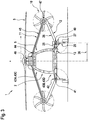
- the Y-Z plane corresponds to the front view plane of the compound helicopter 1 as illustrated in Figure 1 .
- the compound helicopter 1 is symmetrical about the yaw axis 7 and the roll axis (9 in Figure 2 ).
- the compound helicopter 1 comprises at least one propeller 10 that is at least adapted for generating forward thrust in operation.
- the at least one propeller 10 is preferentially mounted to a fixed wing arrangement 11, 12 that is laterally attached to the fuselage 2.
- the compound helicopter 1 comprises two propellers 10, one on each side of the fuselage 2.
- a predetermined distance between an underlying rotational axis of each one of the propellers 10 and the Z-axis 7 preferably corresponds at least essentially to a half wing span 37 of the compound helicopter 1.
- the upper and lower wings 11, 12 are at least interconnected at an associated interconnection region 15. At least one of the two propellers 10 is mounted to the associated interconnection region 15.
- the upper wing 11 preferably exhibits an anhedral angle 34 relative to the horizontal Y-axis 8 of the compound helicopter 1.
- the lower wing 12 is preferentially polyhedral and comprises an inboard section 25 with a span length 30 and an outboard section 26 with a span length 31.
- the span length 31 is at least two to ten times longer than the span length 30.
- the inboard section 25 is preferably connected to the fuselage 2 at the lower wing root joint area 13 and to the outboard section 26 at a sections interconnection region 27.
- the inboard section 25 is an integral part of the fuselage 2.
- the outboard section 26 is connected to the inboard section 25 at the sections interconnection region 27 and to the upper wing 11 at the associated interconnection region 15.
- the outboard section 26 is removably attached to the inboard section 25 at the sections interconnection region 27 and the upper wing 11 is removably attached to the upper wing root joint area 14.
- the inboard section 25 is at least essentially horizontal
- the outboard section 26 is at least essentially inclined upwardly, such that the sections interconnection region 27 preferably defines a dihedral kink of the lower wing 12.
- the compound helicopter 1 further comprises the at least one main rotor 3, the fixed wing arrangement 11, 12, the two propellers 10 and the main landing gear 28.
- each one of the propellers 10 comprises a housing 21 that is rigidly attached to an associated one of the interconnection regions 15 of Figure 1 .
- the propeller disc 10a of each propeller spans up a propeller disc plane 58.
- the fixed wing arrangement 11, 12 comprises the upper and lower wings 11, 12, wherein the lower wing 12 is composed of the inboard section 25 and the outboard section 26.
- the upper wing 11 is removably attached to the upper wing root joint area 14 by means of a hinged root joint 44.
- the fixed wing arrangement out of 11 and 12 shows a positive stagger, with a leading edge of the upper wing 11 being ahead of corresponding leading edges of the inboard section 25 and the outboard section 26 of the lower wing 12.
- the stagger is defined as a difference in longitudinal position of the axis of two wings of the compound helicopter 1.
- the main landing gear 28 is preferentially mainly housed within the inboard section 25 and partially within the fuselage 2.
- the outboard section 26 of the lower wing 12 is removably attached to the inboard section 25 thereof at the sections interconnection region 27 by means of a hinged joint 40 or a clamped joint 41.
- the outboard section 26 comprises wing spars 59 and the fuselage 2 is provided with wing attachment frames 43.
- the hinged joint 40 or the clamped joint 41 preferentially connects the wing spars 59 to the wing attachment frames 43.
- the clamped joint 41 is capable of transferring moments about all axes, i. e. the Z-axis 7 of Figure 1 , the Y-axis 8 and the X-axis 9, whereas the hinged joint 40 is not capable of transferring moments about the longitudinal X-axis 9.
- the first quarter chord line 51 is essentially horizontal, whereas the second quarter chord line 50 preferably exhibits a pronounced forward angle from the horizontal Y-axis 8, i. e. a negative sweep.
- a quarter chord line 19 thereof preferably essentially.-exhibits a rearward sweep angle 17 from the horizontal Y-axis 8.
- the quarter chord line 19 and the quarter chord line 57 of the outboard section 26 illustratively define a relative sweep angle 53 between the upper wing 11 and the outboard section 26.
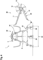
- Figure 3 shows the compound helicopter 1 of Figure 1 with the fuselage 2, the at least one main rotor 3, the fixed wing arrangement 11, 12, the two propellers 10 and the main landing gear 28.
- Each one of the two propellers 10 is preferably powered by an associated propeller drive shaft 45, which is housed within the upper wing 11 and preferentially connects a main gar box 46 of the compound helicopter 1, illustratively arranged on the upper side 5 of the fuselage 2, with a respective propeller gear box 47.
- the fixed wing arrangement 11, 12 comprises the upper and lower wings 11, 12, wherein the lower wing 12 is composed of the inboard section 25 and the outboard section 26.
- the inboard section 25 is a structural part of the fuselage 2 and the main landing gear 28 has an associated trunnion joint 42 that is allocated within the inboard section 25.
- Corresponding attachment spars which are usually provided in the lower wing 12 and in the upper wing 11 (59 in Figure 2 ), are connected to associated wing attachment frames 43C, 43D.
- attachment spars that are provided in the lower wing 12 are connected to lower portions 43B of its associated wing attachment frame 43D allocated within the inboard section 25.
- the upper wing 11 is connected to an upper portion 43A of its associated wing attachment frame 43C, preferably by the hinged root joint 44, which is not capable of transferring moments about the longitudinal X-axis 9 of Figure 2 .
- Figure 4 shows the compound helicopter 1 of Figure 1 with the fuselage 2, the at least one main rotor 3, the fixed wing arrangement 11, 12, one of the two propellers 10 and the main landing gear 28.
- the fixed wing arrangement 11, 12 comprises the upper and lower wings 11, 12, wherein the lower wing 12 is composed of the inboard section 25 and the outboard section 26.
- the compound helicopter 1 is shown in an exemplary transportation condition, corresponding to a transport or storage configuration. More specifically, in this transportation condition the upper wing 11 and the outboard section 26 of the lower wing 12 are preferably dismounted. Consequently, the propeller 10, which is arranged at the interconnection region 15 of the upper and lower wings 11, 12, is likewise dismounted from the compound helicopter 1.
- the upper wing 11, the outboard section 26 and the propeller 10 illustratively define a wing assembly 48.
- the resulting wingless compound helicopter which is illustratively referred to with the reference number 49, is shown with folded rotor blades of the at least one main rotor 3 and stands on its main landing gear 28 and its nose landing gear 29.
- the wingless compound helicopter 49 has a total width 63 that preferably corresponds to a maximum allowable width for transportability.
- the wing assembly 48 including the upper wing 11, the outboard section 26 and the propeller 10 is separately assembled, stored and transported and preferably re-assembled as a pre-assembled unit to the wingless compound helicopter 49. This can easily be done by connecting the upper wing hinged root joint 44 and the lower hinged or clamped joint 40, respectively 41, of Figure 2 and Figure 3 .
- Figure 5 shows the compound helicopter 1 of Figure 1 with the fuselage 2, the at least one main rotor 3, the fixed wing arrangement 11, 12, one of the two propellers 10 and the main landing gear 28.
- the fixed wing arrangement 11, 12 comprises the upper and lower wings 11, 12, wherein the lower wing 12 is composed of the inboard section 25 and the outboard section 26.
- the inboard section 25 now exhibits a negative dihedral angle 32, which is preferably comprised in a range between 0° to 30°.
- the negative dihedral angle 32 defines a pronounced downward angle from the horizontal Y-axis 8. This advantageously results in a shorter required landing gear length 35, a larger upward fillet angle 39 of the inboard section 25 to the fuselage 2, a larger wing interference angle 62 between the outboard section 26 and the upper wing 11, and a more pronounced dihedral angle 32b of the outboard section 26.
- Figure 6 shows the compound helicopter 1 of Figure 1 with the fuselage 2, the at least one main rotor 3, the fixed wing arrangement 11, 12 and the two propellers 10.
- the fixed wing arrangement 11, 12 comprises the upper and lower wings 11, 12, wherein the lower wing 12 is composed of the inboard section 25 and the outboard section 26.
- the inboard section 25 now comprises a pronounced leading edge root extension 54 and a trailing edge root extension 55.
Claims (13)
- Hélicoptère hybride (1) avec un fuselage (2) et au moins un rotor principal (3) qui est au moins adapté pour générer de la portance en fonctionnement, ledit fuselage (2) comprenant une partie inférieure (4) et une partie supérieure (5) qui est opposée à ladite partie inférieure (4), ledit au moins un rotor principal (3) étant aménagé sur ladite partie supérieure (5), dans lequel l'hélicoptère hybride (1) comprend au moins une hélice (10) au moins adaptée pour générer une poussée vers l'avant en fonctionnement, ladite au moins une hélice (10) étant montée sur un agencement de voilure fixe (11, 12) qui est fixé latéralement audit fuselage (2), ledit agencement de voilure fixe (11, 12) comprenant au moins une aile supérieure (11) qui est aménagée dans une zone d'emplanture d'aile supérieure (14) prévue sur ladite partie supérieure (5) dudit fuselage (2) et au moins une aile inférieure (12) qui est aménagée dans une zone d'emplanture d'aile inférieure (13) prévue sur ladite partie inférieure (4) dudit fuselage (2), lesdites ailes supérieure et inférieure (11, 12) étant au moins raccordées entre elles dans une zone d'interconnexion associée (15), chacune des au moins une hélice (10) étant montée dans une zone d'interconnexion associée (15) ; l'hélicoptère hybride (1) étant pourvu d'un train d'atterrissage principal à roues (28),
caractérisé en ce que ladite aile inférieure (12) comprend une section interne (25) définissant une première ligne de quart de corde (51) et un premier axe de résultante des charges (56) et une section externe (26) définissant une seconde ligne de quart de corde (50) et un second axe de résultante des charges (57), ladite section interne (25) étant une part intégrante dudit fuselage (2) à l'emplacement de ladite zone d'emplanture d'aile inférieure (13) et raccordée à ladite section externe (26) à l'emplacement d'une zone d'interconnexion des sections (27), ledit train d'atterrissage principal à roues (28) étant monté sur ladite section interne (25) adjacente à la zone d'interconnexion des sections (27) et ladite section externe (26) étant raccordée à ladite section interne (25) à l'emplacement de la zone d'interconnexion des sections (27) et à ladite aile supérieure (11) à l'emplacement de ladite zone d'interconnexion associée (15), dans lequel ledit second axe de résultante des charges (57) est incliné par rapport audit premier axe de résultante des charges (56) selon un angle de dièdre relatif (33) qui est défini dans un premier plan coordonné, et dans lequel ladite seconde ligne de quart de corde (50) est inclinée par rapport à ladite première ligne de quart de corde (51) selon un angle de flèche relatif (52) qui est défini dans un second plan coordonné. - Hélicoptère hybride (1) selon la revendication 1,
caractérisé en ce que ledit angle de dièdre relatif (33) est compris dans un intervalle s'étendant de 5° à 45°, ledit premier plan coordonné étant défini par un plan en vue de face dudit hélicoptère hybride (1). - Hélicoptère hybride (1) selon la revendication 2,
caractérisé en ce que ledit angle de flèche relatif (52) est compris dans un intervalle s'étendant de 5° à 45°, ledit second plan coordonné étant défini par un plan en vue de dessus dudit hélicoptère hybride (1). - Hélicoptère hybride (1) selon la revendication 1,
caractérisé en ce que ladite aile supérieure (11) est fixée de façon détachable à ladite zone d'emplanture d'aile supérieure (14) et ladite section externe (26) est fixée de façon détachable à ladite section interne (25) à l'emplacement de ladite zone d'interconnexion des sections (27). - Hélicoptère hybride (1) selon la revendication 4,
caractérisé en ce que ladite aile supérieure (11) est fixée de façon détachable à ladite zone d'emplanture d'aile supérieure (14) au moyen d'une emplanture articulée (44) et en ce que ladite section externe (26) est fixée de façon détachable à ladite section interne (25) à l'emplacement de ladite zone d'interconnexion des sections (27) au moyen d'une jointure articulée (40) ou d'une jointure fixe (41). - Hélicoptère hybride (1) selon la revendication 5,
caractérisé en ce que ladite section externe (26) comprend des longerons d'aile (59) et en ce que ledit fuselage (2) est pourvu de cadres de fixation (43) des ailes, ladite jointure articulée (40) ou ladite jointure fixe (41) raccordant lesdits longerons d'aile (59) auxdits cadres de fixation (43) des ailes. - Hélicoptère hybride (1) selon la revendication 1,
caractérisé en ce que ledit train d'atterrissage principal à roues (28) est au moins partiellement rétractable dans ladite section intérieure (25) en fonctionnement. - Hélicoptère hybride (1) selon la revendication 1,
caractérisé en ce que ladite première ligne de quart de corde (51) est au moins essentiellement parallèle au premier plan coordonné avec un écart maximum compris dans un intervalle de ± 5°. - Hélicoptère hybride (1) selon la revendication 1,
caractérisé en ce que ladite section interne (25) présente un angle de dièdre négatif (32a) compris dans un intervalle s'étendant de 0° à 30°. - Hélicoptère hybride (1) selon la revendication 1,
caractérisé en ce que ladite section externe (26) comprend une longueur d'envergure qui est au moins deux à dix fois plus longue qu'une longueur d'envergure (30) de ladite section interne (25). - Hélicoptère hybride (1) selon la revendication 1,
caractérisé en ce que ladite zone d'emplanture d'aile inférieure (13) et ladite zone d'emplanture d'aile supérieure (14) définissent une base de fixation d'aile transversale (60) dans le sens de la hauteur (7) dudit fuselage (2) et une base de fixation d'aile longitudinale (61) dans le sens longitudinal (9) dudit fuselage (2), ladite base de fixation d'aile transversale (60) étant au moins une à cinq fois plus grande que ladite base de fixation d'aile longitudinale (61). - Hélicoptère hybride (1) selon la revendication 1,
caractérisé en ce que ladite au moins une hélice (10) est montée à l'emplacement de ladite zone d'interconnexion associée (15). - Hélicoptère hybride (1) selon la revendication 1,
caractérisé en ce que ledit agencement de voilure fixe (11, 12) comprend au moins une paire d'ailes supérieure et inférieure (11, 12) aménagée sur un côté bâbord dudit hélicoptère hybride (1) et au moins une paire de d'ailes supérieure et inférieure (11, 12) aménagée sur un côté tribord dudit hélicoptère hybride (1), ladite au moins une paire d'ailes supérieure et inférieure (11, 12) aménagée sur ledit côté tribord dudit hélicoptère hybride (1) comprenant ladite au moins une aile supérieure (11) et ladite au moins une aile inférieure (12).
Priority Applications (4)
| Application Number | Priority Date | Filing Date | Title |
|---|---|---|---|
| EP15400040.0A EP3141478B1 (fr) | 2015-09-11 | 2015-09-11 | Hélicoptère combiné |
| KR1020160115755A KR101863905B1 (ko) | 2015-09-11 | 2016-09-08 | 복합형 회전익기 |
| US15/259,219 US10131424B2 (en) | 2015-09-11 | 2016-09-08 | Compound rotorcraft |
| CN201610816451.1A CN106516099B (zh) | 2015-09-11 | 2016-09-09 | 复合旋翼飞行器 |
Applications Claiming Priority (1)
| Application Number | Priority Date | Filing Date | Title |
|---|---|---|---|
| EP15400040.0A EP3141478B1 (fr) | 2015-09-11 | 2015-09-11 | Hélicoptère combiné |
Publications (2)
| Publication Number | Publication Date |
|---|---|
| EP3141478A1 EP3141478A1 (fr) | 2017-03-15 |
| EP3141478B1 true EP3141478B1 (fr) | 2018-11-07 |
Family
ID=54260707
Family Applications (1)
| Application Number | Title | Priority Date | Filing Date |
|---|---|---|---|
| EP15400040.0A Active EP3141478B1 (fr) | 2015-09-11 | 2015-09-11 | Hélicoptère combiné |
Country Status (4)
| Country | Link |
|---|---|
| US (1) | US10131424B2 (fr) |
| EP (1) | EP3141478B1 (fr) |
| KR (1) | KR101863905B1 (fr) |
| CN (1) | CN106516099B (fr) |
Cited By (2)
| Publication number | Priority date | Publication date | Assignee | Title |
|---|---|---|---|---|
| WO2021138470A1 (fr) * | 2019-12-31 | 2021-07-08 | Russ Jonathan Christian | Aéronef à hélices positionnées en bout d'aile |
| EP3865402A1 (fr) | 2020-02-17 | 2021-08-18 | AIRBUS HELICOPTERS DEUTSCHLAND GmbH | Hélicoptère combiné sans queue |
Families Citing this family (28)
| Publication number | Priority date | Publication date | Assignee | Title |
|---|---|---|---|---|
| US10926874B2 (en) * | 2016-01-15 | 2021-02-23 | Aurora Flight Sciences Corporation | Hybrid propulsion vertical take-off and landing aircraft |
| US10822101B2 (en) | 2017-07-21 | 2020-11-03 | General Electric Company | Vertical takeoff and landing aircraft having a forward thrust propulsor |
| US10836481B2 (en) | 2017-11-09 | 2020-11-17 | Bell Helicopter Textron Inc. | Biplane tiltrotor aircraft |
| EP3486171B1 (fr) | 2017-11-20 | 2020-02-05 | AIRBUS HELICOPTERS DEUTSCHLAND GmbH | Aeronef presentant plusieurs paires d'ailes reliees entre elles |
| EP3505443B1 (fr) * | 2017-12-27 | 2020-03-11 | LEONARDO S.p.A. | Avion convertible et son procédé de commande |
| BR112021001262A2 (pt) * | 2018-07-23 | 2021-04-20 | Airgility, Inc. | plataforma de veículo de sistema de partida, e, método de operação de uma plataforma de veículo de sistema de partida . |
| FR3084318B1 (fr) * | 2018-07-25 | 2020-06-26 | Airbus Helicopters | Procede et dispositif de gestion de l'energie d'une installation motrice hybride d'un aeronef multirotor |
| CN108859639B (zh) * | 2018-08-15 | 2021-04-23 | 长沙神弓信息科技有限公司 | 一种无尾桨高速单旋翼两栖探测直升机 |
| US11912405B2 (en) * | 2018-10-02 | 2024-02-27 | Embraer S.A. | Vertical and short takeoff and landing (VSTOL) aircraft |
| EP3650341B1 (fr) | 2018-11-07 | 2021-03-24 | AIRBUS HELICOPTERS DEUTSCHLAND GmbH | Hélicoptère composé doté d'un agencement à voilure fixe |
| US11148799B2 (en) * | 2018-11-26 | 2021-10-19 | Textron Innovations Inc. | Tilting duct compound helicopter |
| CN109533319A (zh) * | 2018-12-07 | 2019-03-29 | 湖北航天飞行器研究所 | 一种具有搭接翼的倾转旋翼无人飞行器结构系统 |
| CN111319750B (zh) * | 2018-12-14 | 2023-06-09 | 空客直升机德国有限公司 | 支撑翼飞行器 |
| GB2610940B (en) * | 2019-01-17 | 2023-10-18 | Rayne Damian | An aircraft |
| GB2610939B (en) * | 2019-01-17 | 2023-10-18 | Rayne Damian | An aircraft |
| GB2581951B (en) * | 2019-01-17 | 2022-11-30 | Rayne Damian | An aircraft |
| EP3702277B1 (fr) | 2019-02-27 | 2021-01-27 | AIRBUS HELICOPTERS DEUTSCHLAND GmbH | Aéronef multirotor adapté pour décollage et atterrissage verticaux (adav) |
| NL1043177B1 (en) * | 2019-03-04 | 2020-09-17 | Pal V Ip B V | Vertical Take Off and Landing Vehicle |
| CN109987223B (zh) * | 2019-04-02 | 2023-03-10 | 夏季风 | 一种联接翼构型的新型垂直起降无人机 |
| JP2022534294A (ja) * | 2019-05-29 | 2022-07-28 | クラフト エアロスペース テクノロジーズ, インコーポレイテッド | タンデム翼および分散型推進システムを使用する新規の航空機設計 |
| WO2020250010A1 (fr) | 2019-06-12 | 2020-12-17 | Chong Qing Liang Jiang Aircraft Design Institute Ltd. | Procédé de fonctionnement d'un véhicule uav convertible |
| CN110481771A (zh) * | 2019-09-26 | 2019-11-22 | 成都纵横大鹏无人机科技有限公司 | 可垂直起降的固定翼飞行器及无人机系统 |
| FR3103786A1 (fr) | 2019-11-29 | 2021-06-04 | Airbus Helicopters | Giravion hybride comportant au moins une hélice propulsive ou tractive et procédé de pilotage associé. |
| CN112173084B (zh) * | 2020-09-25 | 2023-04-07 | 中国直升机设计研究所 | 无人高速直升机可收放主起落架承力结构及其设计方法 |
| EP4008628B1 (fr) | 2020-12-02 | 2023-02-08 | AIRBUS HELICOPTERS DEUTSCHLAND GmbH | Girodyne à ailes contreventées et en configuration à ailes jointes |
| EP4008627B1 (fr) | 2020-12-02 | 2024-03-13 | AIRBUS HELICOPTERS DEUTSCHLAND GmbH | Girodyne à ailes renforcées dans une configuration d'ailes jointes |
| TWI763447B (zh) * | 2021-04-20 | 2022-05-01 | 林瑤章 | 雙翼飛行裝置 |
| JP2024000086A (ja) * | 2022-06-20 | 2024-01-05 | 国立研究開発法人宇宙航空研究開発機構 | コンパウンドヘリコプタ |
Family Cites Families (19)
| Publication number | Priority date | Publication date | Assignee | Title |
|---|---|---|---|---|
| US1995090A (en) * | 1932-09-02 | 1935-03-19 | Giuseppe M Bellanca | Convertible airplane |
| US2290850A (en) * | 1940-10-09 | 1942-07-21 | Brewster Aeronautical Corp | Folding wing airplane |
| US3981460A (en) * | 1973-08-30 | 1976-09-21 | Robert N. Starr | Staggered channel wing-type aircraft |
| US4146199A (en) * | 1977-08-01 | 1979-03-27 | Phoenixbird, Inc. | Multi-winged lifting body aircraft |
| US4856736A (en) * | 1987-06-26 | 1989-08-15 | Skywardens Limited | Aircraft with paired aerofoils |
| US5046684A (en) | 1989-02-09 | 1991-09-10 | Julian Wolkovitch | Airplane with braced wings and pivoting propulsion devices |
| US6098923A (en) * | 1998-03-13 | 2000-08-08 | Lockheed Martin Corporation | Aircraft structure to improve directional stability |
| US6974105B2 (en) * | 2003-01-09 | 2005-12-13 | Roger N Pham | High performance VTOL convertiplanes |
| US20050230519A1 (en) | 2003-09-10 | 2005-10-20 | Hurley Francis X | Counter-quad tilt-wing aircraft design |
| US8657226B1 (en) * | 2007-01-12 | 2014-02-25 | John William McGinnis | Efficient control and stall prevention in advanced configuration aircraft |
| FR2916418B1 (fr) | 2007-05-22 | 2009-08-28 | Eurocopter France | Helicoptere hybride rapide a grande distance franchissable. |
| KR20090054027A (ko) * | 2007-11-26 | 2009-05-29 | 임채호 | 가변형 회전익을 이용한 수직이착륙기 |
| ES2377637B1 (es) * | 2009-04-07 | 2013-02-28 | Airbus Operations, S.L. | Avión con configuración alar en caja lambda. |
| FR2976912B1 (fr) | 2011-06-24 | 2014-02-21 | Eurocopter France | Aeronef a voilure tournante et a voilure fixe. |
| FR2977948B1 (fr) | 2011-07-12 | 2014-11-07 | Eurocopter France | Procede de pilotage automatique d'un aeronef a voilure tournante comprenant au moins une helice propulsive, dispositif de pilotage automatique et aeronef |
| TWI538852B (zh) * | 2011-07-19 | 2016-06-21 | 季航空股份有限公司 | 個人飛機 |
| EP2690011B1 (fr) | 2012-07-27 | 2016-09-14 | AIRBUS HELICOPTERS DEUTSCHLAND GmbH | Hélicoptère combiné |
| FR3002516B1 (fr) * | 2013-02-22 | 2015-04-03 | Eurocopter France | Giravion a double fuselage |
| CN204473135U (zh) * | 2014-12-26 | 2015-07-15 | 金良 | 一种变翼式无人机 |
-
2015
- 2015-09-11 EP EP15400040.0A patent/EP3141478B1/fr active Active
-
2016
- 2016-09-08 KR KR1020160115755A patent/KR101863905B1/ko active IP Right Grant
- 2016-09-08 US US15/259,219 patent/US10131424B2/en active Active
- 2016-09-09 CN CN201610816451.1A patent/CN106516099B/zh active Active
Non-Patent Citations (1)
| Title |
|---|
| None * |
Cited By (2)
| Publication number | Priority date | Publication date | Assignee | Title |
|---|---|---|---|---|
| WO2021138470A1 (fr) * | 2019-12-31 | 2021-07-08 | Russ Jonathan Christian | Aéronef à hélices positionnées en bout d'aile |
| EP3865402A1 (fr) | 2020-02-17 | 2021-08-18 | AIRBUS HELICOPTERS DEUTSCHLAND GmbH | Hélicoptère combiné sans queue |
Also Published As
| Publication number | Publication date |
|---|---|
| CN106516099A (zh) | 2017-03-22 |
| CN106516099B (zh) | 2019-12-10 |
| US10131424B2 (en) | 2018-11-20 |
| KR101863905B1 (ko) | 2018-06-01 |
| EP3141478A1 (fr) | 2017-03-15 |
| KR20170031638A (ko) | 2017-03-21 |
| US20170197709A1 (en) | 2017-07-13 |
Similar Documents
| Publication | Publication Date | Title |
|---|---|---|
| US10131424B2 (en) | Compound rotorcraft | |
| CN111619785B (zh) | 适于垂直起飞和着陆的多旋翼飞行器 | |
| US9321526B2 (en) | Compound helicopter | |
| EP3439951B1 (fr) | Ensembles d'ailes rotatives pour un tailsitter | |
| US8387913B2 (en) | Compact aircraft wing folding systems and methods | |
| US9266607B2 (en) | Compound helicopter with tail booms | |
| CN101559832B (zh) | 快速远程的混合式直升机 | |
| CN101875399B (zh) | 一种采用并列式共轴双旋翼的倾转旋翼飞机 | |
| EP2690012A1 (fr) | Giravion semi-convertible | |
| EP3650341B1 (fr) | Hélicoptère composé doté d'un agencement à voilure fixe | |
| EP3299280B1 (fr) | Aéronef pliable comportant des ailes de stabilisation à dièdre négatif | |
| EP3771638B1 (fr) | Système de rotor de levage | |
| CN106218887A (zh) | 一种分布式动力装置布局的垂直起降飞行器 | |
| CN114430725A (zh) | 使用固定前倾旋翼来模拟刚性机翼空气动力学的垂直起降飞行器 | |
| CN103158856A (zh) | 可短距起降的轻型螺旋桨飞翼飞机 | |
| US11760474B2 (en) | VTOL box-wing multirotor aerial vehicle | |
| EP4008628B1 (fr) | Girodyne à ailes contreventées et en configuration à ailes jointes | |
| CN206202685U (zh) | 一种分布式动力装置布局的垂直起降飞行器 | |
| EP3865402B1 (fr) | Hélicoptère combiné sans queue |
Legal Events
| Date | Code | Title | Description |
|---|---|---|---|
| PUAI | Public reference made under article 153(3) epc to a published international application that has entered the european phase |
Free format text: ORIGINAL CODE: 0009012 |
|
| STAA | Information on the status of an ep patent application or granted ep patent |
Free format text: STATUS: THE APPLICATION HAS BEEN PUBLISHED |
|
| STAA | Information on the status of an ep patent application or granted ep patent |
Free format text: STATUS: REQUEST FOR EXAMINATION WAS MADE |
|
| AK | Designated contracting states |
Kind code of ref document: A1 Designated state(s): AL AT BE BG CH CY CZ DE DK EE ES FI FR GB GR HR HU IE IS IT LI LT LU LV MC MK MT NL NO PL PT RO RS SE SI SK SM TR |
|
| AX | Request for extension of the european patent |
Extension state: BA ME |
|
| 17P | Request for examination filed |
Effective date: 20170220 |
|
| RBV | Designated contracting states (corrected) |
Designated state(s): AL AT BE BG CH CY CZ DE DK EE ES FI FR GB GR HR HU IE IS IT LI LT LU LV MC MK MT NL NO PL PT RO RS SE SI SK SM TR |
|
| STAA | Information on the status of an ep patent application or granted ep patent |
Free format text: STATUS: EXAMINATION IS IN PROGRESS |
|
| 17Q | First examination report despatched |
Effective date: 20170720 |
|
| GRAP | Despatch of communication of intention to grant a patent |
Free format text: ORIGINAL CODE: EPIDOSNIGR1 |
|
| STAA | Information on the status of an ep patent application or granted ep patent |
Free format text: STATUS: GRANT OF PATENT IS INTENDED |
|
| INTG | Intention to grant announced |
Effective date: 20180719 |
|
| GRAS | Grant fee paid |
Free format text: ORIGINAL CODE: EPIDOSNIGR3 |
|
| GRAA | (expected) grant |
Free format text: ORIGINAL CODE: 0009210 |
|
| STAA | Information on the status of an ep patent application or granted ep patent |
Free format text: STATUS: THE PATENT HAS BEEN GRANTED |
|
| AK | Designated contracting states |
Kind code of ref document: B1 Designated state(s): AL AT BE BG CH CY CZ DE DK EE ES FI FR GB GR HR HU IE IS IT LI LT LU LV MC MK MT NL NO PL PT RO RS SE SI SK SM TR |
|
| REG | Reference to a national code |
Ref country code: GB Ref legal event code: FG4D |
|
| RIN1 | Information on inventor provided before grant (corrected) |
Inventor name: BLACHA, MARTIN Inventor name: FINK, AXEL |
|
| REG | Reference to a national code |
Ref country code: CH Ref legal event code: EP Ref country code: AT Ref legal event code: REF Ref document number: 1061751 Country of ref document: AT Kind code of ref document: T Effective date: 20181115 |
|
| REG | Reference to a national code |
Ref country code: DE Ref legal event code: R096 Ref document number: 602015019449 Country of ref document: DE |
|
| REG | Reference to a national code |
Ref country code: IE Ref legal event code: FG4D |
|
| REG | Reference to a national code |
Ref country code: NL Ref legal event code: MP Effective date: 20181107 |
|
| REG | Reference to a national code |
Ref country code: LT Ref legal event code: MG4D |
|
| REG | Reference to a national code |
Ref country code: AT Ref legal event code: MK05 Ref document number: 1061751 Country of ref document: AT Kind code of ref document: T Effective date: 20181107 |
|
| PG25 | Lapsed in a contracting state [announced via postgrant information from national office to epo] |
Ref country code: BG Free format text: LAPSE BECAUSE OF FAILURE TO SUBMIT A TRANSLATION OF THE DESCRIPTION OR TO PAY THE FEE WITHIN THE PRESCRIBED TIME-LIMIT Effective date: 20190207 Ref country code: IS Free format text: LAPSE BECAUSE OF FAILURE TO SUBMIT A TRANSLATION OF THE DESCRIPTION OR TO PAY THE FEE WITHIN THE PRESCRIBED TIME-LIMIT Effective date: 20190307 Ref country code: HR Free format text: LAPSE BECAUSE OF FAILURE TO SUBMIT A TRANSLATION OF THE DESCRIPTION OR TO PAY THE FEE WITHIN THE PRESCRIBED TIME-LIMIT Effective date: 20181107 Ref country code: LV Free format text: LAPSE BECAUSE OF FAILURE TO SUBMIT A TRANSLATION OF THE DESCRIPTION OR TO PAY THE FEE WITHIN THE PRESCRIBED TIME-LIMIT Effective date: 20181107 Ref country code: FI Free format text: LAPSE BECAUSE OF FAILURE TO SUBMIT A TRANSLATION OF THE DESCRIPTION OR TO PAY THE FEE WITHIN THE PRESCRIBED TIME-LIMIT Effective date: 20181107 Ref country code: ES Free format text: LAPSE BECAUSE OF FAILURE TO SUBMIT A TRANSLATION OF THE DESCRIPTION OR TO PAY THE FEE WITHIN THE PRESCRIBED TIME-LIMIT Effective date: 20181107 Ref country code: AT Free format text: LAPSE BECAUSE OF FAILURE TO SUBMIT A TRANSLATION OF THE DESCRIPTION OR TO PAY THE FEE WITHIN THE PRESCRIBED TIME-LIMIT Effective date: 20181107 Ref country code: NO Free format text: LAPSE BECAUSE OF FAILURE TO SUBMIT A TRANSLATION OF THE DESCRIPTION OR TO PAY THE FEE WITHIN THE PRESCRIBED TIME-LIMIT Effective date: 20190207 Ref country code: LT Free format text: LAPSE BECAUSE OF FAILURE TO SUBMIT A TRANSLATION OF THE DESCRIPTION OR TO PAY THE FEE WITHIN THE PRESCRIBED TIME-LIMIT Effective date: 20181107 |
|
| PG25 | Lapsed in a contracting state [announced via postgrant information from national office to epo] |
Ref country code: PT Free format text: LAPSE BECAUSE OF FAILURE TO SUBMIT A TRANSLATION OF THE DESCRIPTION OR TO PAY THE FEE WITHIN THE PRESCRIBED TIME-LIMIT Effective date: 20190307 Ref country code: NL Free format text: LAPSE BECAUSE OF FAILURE TO SUBMIT A TRANSLATION OF THE DESCRIPTION OR TO PAY THE FEE WITHIN THE PRESCRIBED TIME-LIMIT Effective date: 20181107 Ref country code: SE Free format text: LAPSE BECAUSE OF FAILURE TO SUBMIT A TRANSLATION OF THE DESCRIPTION OR TO PAY THE FEE WITHIN THE PRESCRIBED TIME-LIMIT Effective date: 20181107 Ref country code: RS Free format text: LAPSE BECAUSE OF FAILURE TO SUBMIT A TRANSLATION OF THE DESCRIPTION OR TO PAY THE FEE WITHIN THE PRESCRIBED TIME-LIMIT Effective date: 20181107 Ref country code: GR Free format text: LAPSE BECAUSE OF FAILURE TO SUBMIT A TRANSLATION OF THE DESCRIPTION OR TO PAY THE FEE WITHIN THE PRESCRIBED TIME-LIMIT Effective date: 20190208 Ref country code: AL Free format text: LAPSE BECAUSE OF FAILURE TO SUBMIT A TRANSLATION OF THE DESCRIPTION OR TO PAY THE FEE WITHIN THE PRESCRIBED TIME-LIMIT Effective date: 20181107 |
|
| PG25 | Lapsed in a contracting state [announced via postgrant information from national office to epo] |
Ref country code: PL Free format text: LAPSE BECAUSE OF FAILURE TO SUBMIT A TRANSLATION OF THE DESCRIPTION OR TO PAY THE FEE WITHIN THE PRESCRIBED TIME-LIMIT Effective date: 20181107 Ref country code: CZ Free format text: LAPSE BECAUSE OF FAILURE TO SUBMIT A TRANSLATION OF THE DESCRIPTION OR TO PAY THE FEE WITHIN THE PRESCRIBED TIME-LIMIT Effective date: 20181107 Ref country code: DK Free format text: LAPSE BECAUSE OF FAILURE TO SUBMIT A TRANSLATION OF THE DESCRIPTION OR TO PAY THE FEE WITHIN THE PRESCRIBED TIME-LIMIT Effective date: 20181107 |
|
| REG | Reference to a national code |
Ref country code: DE Ref legal event code: R097 Ref document number: 602015019449 Country of ref document: DE |
|
| PG25 | Lapsed in a contracting state [announced via postgrant information from national office to epo] |
Ref country code: EE Free format text: LAPSE BECAUSE OF FAILURE TO SUBMIT A TRANSLATION OF THE DESCRIPTION OR TO PAY THE FEE WITHIN THE PRESCRIBED TIME-LIMIT Effective date: 20181107 Ref country code: SM Free format text: LAPSE BECAUSE OF FAILURE TO SUBMIT A TRANSLATION OF THE DESCRIPTION OR TO PAY THE FEE WITHIN THE PRESCRIBED TIME-LIMIT Effective date: 20181107 Ref country code: SK Free format text: LAPSE BECAUSE OF FAILURE TO SUBMIT A TRANSLATION OF THE DESCRIPTION OR TO PAY THE FEE WITHIN THE PRESCRIBED TIME-LIMIT Effective date: 20181107 Ref country code: RO Free format text: LAPSE BECAUSE OF FAILURE TO SUBMIT A TRANSLATION OF THE DESCRIPTION OR TO PAY THE FEE WITHIN THE PRESCRIBED TIME-LIMIT Effective date: 20181107 |
|
| PLBE | No opposition filed within time limit |
Free format text: ORIGINAL CODE: 0009261 |
|
| STAA | Information on the status of an ep patent application or granted ep patent |
Free format text: STATUS: NO OPPOSITION FILED WITHIN TIME LIMIT |
|
| 26N | No opposition filed |
Effective date: 20190808 |
|
| PG25 | Lapsed in a contracting state [announced via postgrant information from national office to epo] |
Ref country code: SI Free format text: LAPSE BECAUSE OF FAILURE TO SUBMIT A TRANSLATION OF THE DESCRIPTION OR TO PAY THE FEE WITHIN THE PRESCRIBED TIME-LIMIT Effective date: 20181107 |
|
| PG25 | Lapsed in a contracting state [announced via postgrant information from national office to epo] |
Ref country code: TR Free format text: LAPSE BECAUSE OF FAILURE TO SUBMIT A TRANSLATION OF THE DESCRIPTION OR TO PAY THE FEE WITHIN THE PRESCRIBED TIME-LIMIT Effective date: 20181107 |
|
| PG25 | Lapsed in a contracting state [announced via postgrant information from national office to epo] |
Ref country code: MC Free format text: LAPSE BECAUSE OF FAILURE TO SUBMIT A TRANSLATION OF THE DESCRIPTION OR TO PAY THE FEE WITHIN THE PRESCRIBED TIME-LIMIT Effective date: 20181107 |
|
| REG | Reference to a national code |
Ref country code: CH Ref legal event code: PL |
|
| PG25 | Lapsed in a contracting state [announced via postgrant information from national office to epo] |
Ref country code: LU Free format text: LAPSE BECAUSE OF NON-PAYMENT OF DUE FEES Effective date: 20190911 Ref country code: IE Free format text: LAPSE BECAUSE OF NON-PAYMENT OF DUE FEES Effective date: 20190911 Ref country code: CH Free format text: LAPSE BECAUSE OF NON-PAYMENT OF DUE FEES Effective date: 20190930 Ref country code: LI Free format text: LAPSE BECAUSE OF NON-PAYMENT OF DUE FEES Effective date: 20190930 |
|
| REG | Reference to a national code |
Ref country code: BE Ref legal event code: MM Effective date: 20190930 |
|
| PG25 | Lapsed in a contracting state [announced via postgrant information from national office to epo] |
Ref country code: BE Free format text: LAPSE BECAUSE OF NON-PAYMENT OF DUE FEES Effective date: 20190930 |
|
| PG25 | Lapsed in a contracting state [announced via postgrant information from national office to epo] |
Ref country code: CY Free format text: LAPSE BECAUSE OF FAILURE TO SUBMIT A TRANSLATION OF THE DESCRIPTION OR TO PAY THE FEE WITHIN THE PRESCRIBED TIME-LIMIT Effective date: 20181107 |
|
| PG25 | Lapsed in a contracting state [announced via postgrant information from national office to epo] |
Ref country code: MT Free format text: LAPSE BECAUSE OF FAILURE TO SUBMIT A TRANSLATION OF THE DESCRIPTION OR TO PAY THE FEE WITHIN THE PRESCRIBED TIME-LIMIT Effective date: 20181107 Ref country code: HU Free format text: LAPSE BECAUSE OF FAILURE TO SUBMIT A TRANSLATION OF THE DESCRIPTION OR TO PAY THE FEE WITHIN THE PRESCRIBED TIME-LIMIT; INVALID AB INITIO Effective date: 20150911 |
|
| PG25 | Lapsed in a contracting state [announced via postgrant information from national office to epo] |
Ref country code: MK Free format text: LAPSE BECAUSE OF FAILURE TO SUBMIT A TRANSLATION OF THE DESCRIPTION OR TO PAY THE FEE WITHIN THE PRESCRIBED TIME-LIMIT Effective date: 20181107 |
|
| P01 | Opt-out of the competence of the unified patent court (upc) registered |
Effective date: 20230530 |
|
| PGFP | Annual fee paid to national office [announced via postgrant information from national office to epo] |
Ref country code: GB Payment date: 20230920 Year of fee payment: 9 |
|
| PGFP | Annual fee paid to national office [announced via postgrant information from national office to epo] |
Ref country code: FR Payment date: 20230928 Year of fee payment: 9 Ref country code: DE Payment date: 20230920 Year of fee payment: 9 |
|
| PGFP | Annual fee paid to national office [announced via postgrant information from national office to epo] |
Ref country code: IT Payment date: 20230927 Year of fee payment: 9 |