EP3771638B1 - Système de rotor de levage - Google Patents
Système de rotor de levage Download PDFInfo
- Publication number
- EP3771638B1 EP3771638B1 EP20187367.6A EP20187367A EP3771638B1 EP 3771638 B1 EP3771638 B1 EP 3771638B1 EP 20187367 A EP20187367 A EP 20187367A EP 3771638 B1 EP3771638 B1 EP 3771638B1
- Authority
- EP
- European Patent Office
- Prior art keywords
- rotor
- lift
- wing
- wing segment
- blades
- Prior art date
- Legal status (The legal status is an assumption and is not a legal conclusion. Google has not performed a legal analysis and makes no representation as to the accuracy of the status listed.)
- Active
Links
- 239000011800 void material Substances 0.000 claims description 15
- 230000007613 environmental effect Effects 0.000 description 2
- 239000000463 material Substances 0.000 description 2
- 230000000712 assembly Effects 0.000 description 1
- 238000000429 assembly Methods 0.000 description 1
- 238000005265 energy consumption Methods 0.000 description 1
- 238000004519 manufacturing process Methods 0.000 description 1
- 230000007246 mechanism Effects 0.000 description 1
- 238000012986 modification Methods 0.000 description 1
- 230000004048 modification Effects 0.000 description 1
Images


Classifications
-
- B—PERFORMING OPERATIONS; TRANSPORTING
- B64—AIRCRAFT; AVIATION; COSMONAUTICS
- B64C—AEROPLANES; HELICOPTERS
- B64C29/00—Aircraft capable of landing or taking-off vertically, e.g. vertical take-off and landing [VTOL] aircraft
- B64C29/0008—Aircraft capable of landing or taking-off vertically, e.g. vertical take-off and landing [VTOL] aircraft having its flight directional axis horizontal when grounded
- B64C29/0016—Aircraft capable of landing or taking-off vertically, e.g. vertical take-off and landing [VTOL] aircraft having its flight directional axis horizontal when grounded the lift during taking-off being created by free or ducted propellers or by blowers
- B64C29/0025—Aircraft capable of landing or taking-off vertically, e.g. vertical take-off and landing [VTOL] aircraft having its flight directional axis horizontal when grounded the lift during taking-off being created by free or ducted propellers or by blowers the propellers being fixed relative to the fuselage
-
- B—PERFORMING OPERATIONS; TRANSPORTING
- B64—AIRCRAFT; AVIATION; COSMONAUTICS
- B64C—AEROPLANES; HELICOPTERS
- B64C11/00—Propellers, e.g. of ducted type; Features common to propellers and rotors for rotorcraft
- B64C11/16—Blades
- B64C11/20—Constructional features
- B64C11/28—Collapsible or foldable blades
-
- B—PERFORMING OPERATIONS; TRANSPORTING
- B64—AIRCRAFT; AVIATION; COSMONAUTICS
- B64C—AEROPLANES; HELICOPTERS
- B64C27/00—Rotorcraft; Rotors peculiar thereto
- B64C27/22—Compound rotorcraft, i.e. aircraft using in flight the features of both aeroplane and rotorcraft
- B64C27/26—Compound rotorcraft, i.e. aircraft using in flight the features of both aeroplane and rotorcraft characterised by provision of fixed wings
-
- B—PERFORMING OPERATIONS; TRANSPORTING
- B64—AIRCRAFT; AVIATION; COSMONAUTICS
- B64C—AEROPLANES; HELICOPTERS
- B64C39/00—Aircraft not otherwise provided for
- B64C39/06—Aircraft not otherwise provided for having disc- or ring-shaped wings
- B64C39/068—Aircraft not otherwise provided for having disc- or ring-shaped wings having multiple wings joined at the tips
-
- B—PERFORMING OPERATIONS; TRANSPORTING
- B64—AIRCRAFT; AVIATION; COSMONAUTICS
- B64C—AEROPLANES; HELICOPTERS
- B64C39/00—Aircraft not otherwise provided for
- B64C39/12—Canard-type aircraft
-
- B—PERFORMING OPERATIONS; TRANSPORTING
- B64—AIRCRAFT; AVIATION; COSMONAUTICS
- B64C—AEROPLANES; HELICOPTERS
- B64C7/00—Structures or fairings not otherwise provided for
-
- B—PERFORMING OPERATIONS; TRANSPORTING
- B64—AIRCRAFT; AVIATION; COSMONAUTICS
- B64C—AEROPLANES; HELICOPTERS
- B64C9/00—Adjustable control surfaces or members, e.g. rudders
-
- B—PERFORMING OPERATIONS; TRANSPORTING
- B64—AIRCRAFT; AVIATION; COSMONAUTICS
- B64C—AEROPLANES; HELICOPTERS
- B64C11/00—Propellers, e.g. of ducted type; Features common to propellers and rotors for rotorcraft
- B64C11/30—Blade pitch-changing mechanisms
-
- B—PERFORMING OPERATIONS; TRANSPORTING
- B64—AIRCRAFT; AVIATION; COSMONAUTICS
- B64C—AEROPLANES; HELICOPTERS
- B64C9/00—Adjustable control surfaces or members, e.g. rudders
- B64C2009/005—Ailerons
Definitions
- the present disclosure relates to a lift rotor system for a vertical take-off and landing (VTOL) aircraft, and provides an arrangement as set out in the appended claims. It also relates to a wing segment for a VTOL aircraft and a VTOL aircraft having such a lift rotor arrangement and wing segment.
- VTOL vertical take-off and landing
- Lift-plus-cruise vertical take-off and landing (VTOL) aircraft can operate in both airplane and helicopter modes. Their configuration is based on utilising separate systems for hover lift and cruise thrust. They carry lift rotors which are active during vertical take-off and landing, and cruise rotors which are active during cruise.
- the inactive lift rotors can generate significant amounts of drag during cruise and thus compromise the performance of the aircraft with associated penalties in range and/or payload capability.
- European patent EP 3418186 A1 discloses an apparatus for a VTOL aircraft comprising a rotor arrangement with a first and second rotor blade moveable between a first extended position where the rotor can provide lift and a second, retracted position wherein the rotor is stored within the wing of the VTOL aircraft.
- United States patent US 6622962 B1 discloses a VTOL aircraft including a rotor blade assembly capable of vertical lift.
- the rotor blade assembly can be stowed in an encapsulating housing when not in use.
- a lift rotor arrangement for a VTOL aircraft comprising: a fairing mounted on a wing segment; and first and second rotor blades mounted on a first shaft extending vertically from the fairing, wherein the first shaft is movable from an extended position in which the first and second rotor blades are vertically spaced above the wing segment and are rotatable to provide vertical lift, and a retracted position in which the first and second rotor blades are rotationally-fixed with the first rotor blade stowed within the wing segment, the rotor blades being aerofoils with a leading edge and a trailing edge, wherein, in the retracted position, the trailing edge of the first rotor blade is aligned with a rearward edge of the wing segment (i.e. rearward in the direction of forward cruise motion).
- the advantage of such a configuration is that it provides an alternative means for reducing drag caused by the rotor arrangement on a VTOL aircraft using such a lift rotor arrangement during the VTOL aircraft's cruise phase.
- Another advantage of such a configuration is that it provides an improved means for locking the rotors into a safe position during cruise.
- the rotor blades are clear of the wing segment and can rotate to provide vertical lift to the VTOL aircraft.
- the VTOL aircraft In the retracted position, the VTOL aircraft is driven forward by a cruise thrust system and the retraction of the shaft and rotor blades towards the wing segment with the first rotor blade stowed within the wing segment reduces drag during cruise.
- the first rotor blade in the retracted position, is stowed within a recess provided in a surface (e.g. an upper surface) of the wing segment e.g. so that the first rotor blade is flush with the upper surface of the wing segment.
- Such a configuration provides a combination of safe containment of the rotor blade, whilst allowing the opposite surface of the wing (e.g. the lower surface, when the rotor blade recess is provided in the upper surface) to be specifically shaped for optimum aerodynamic performance.
- the first rotor blade in the retracted position, is stowed within a void provided in the wing segment so as to form a portion of the wing segment e.g. with the first rotor blade flush with the upper surface and the opposing lower surface of the wing segment.
- voids within the wing allows for further weight savings as less material is used in the wings, and allows the downdraft created by the rotors to affect a greater area when a VTOL using such a lift rotor arrangement is deployed in helicopter mode.
- the lift rotor arrangement further comprises third and fourth rotor blades mounted on a second shaft extending vertically from the fairing in an opposing vertical direction to the first shaft, wherein the second shaft is movable between an extended position in which the third and fourth rotor blades are vertically spaced below the wing segment and are rotatable in an opposing direction to the first and second blades, and a retracted position in which the third and fourth rotor blades are rotationally-fixed with the third rotor blade stowed within a surface of the wing segment.
- Such a contra-rotating rotor arrangement can cancel out torque within the single wing system, and can be more efficient than a single propeller system.
- the third rotor blade in the retracted position, is stowed within a recess provided in a surface (e.g. a lower surface) of the wing segment (opposite to the surface within which the first rotor is stowed) e.g. so that the third rotor blade is flush with the lower surface of the wing segment.
- a surface e.g. a lower surface
- the third rotor blade is flush with the lower surface of the wing segment.
- the wing segment is a box-wing segment having upper and lower wing portions and the fairing is provided at the joint between the upper and lower wing portions.
- the upper wing portion may be a forward-swept portion and the lower wing portion may be a swept-back portion or vice versa.
- the upper surface of the wing segment may be provided on the upper wing portion and the lower surface of the wing segment may be provided on the lower wing portion.
- Box wing designs can provide extra stiffness to the structure of a VTOL aircraft using such a lift rotor arrangement and reduce aerodynamic losses at the wing tips.
- the first rotor blade in the retracted position, is stowed within a void provided in the upper wing portion so as to form an integral part of the upper wing portion e.g. with the first rotor blade flush with an upper surface and a lower surface of the upper wing portion and/or the third rotor blade is stowed within a void provided in the lower wing portion so as to form an integral part of the lower wing portion e.g. with the third rotor blade flush with an upper surface and a lower surface of the lower wing portion.
- Such a design allows further weight savings as less material is used within the wing portions.
- the leading edge of the first rotor blade may be aligned with a forward edge of the void or recess in the wing segment.
- the first rotor blade may have a width and length that substantially match the width (between the forward and rearward edges) and length of the void or recess in the wing segment.
- the trailing edge of the third rotor blade may be aligned with a rearward edge of the wing segment (i.e. rearward in the direction of forwarding cruise motion).
- the leading edge of the third rotor blade may be aligned with a forward edge of the void or recess in the wing segment.
- the third rotor blade may have a width and length that substantially match the width (between the forward and rearward edges) and length of the void or recess in the wing segment.
- the first and/or third rotor blades have an adjustable/variable pitch i.e. they can be rotated around an axis substantially perpendicular to the axis of the respective shaft.
- the second and/or fourth rotor blades can also be rotated around the axis substantially perpendicular to the axis of the shaft (together with and in the same direction as or opposite direction to the first and/or third rotor blades) to act as an aileron/elevon in the retracted position and provide the same advantages as previously discussed.
- the rotor blades are simple symmetric aerofoils with a maximum thickness at 50% of the chord. This design provides the advantage that the drag created by the external rotor (which protrudes beyond the faring when the rotor is in the stowed position) travelling through the air in the opposite direction compared to when it is rotating to provide lift is reduced.
- first and/or second shaft may be provided with further rotor blades in addition to the first and second/third and fourth. Extra blades can increase the amount of lift the rotors can generate, or allow the rotors to rotate more slowly whilst producing the same amount of lift force.
- each shaft retracts and extends electrically between the extended and retracted positions.
- the lift rotor arrangement may further comprise a motor or a respective motor (e.g. an electric motor) for retracting and extending each shaft between the extended and retracted positions.
- the motor(s) may be housed within the fairing.
- Such an arrangement can be used within all-electric or hybrid VTOL aircraft, reducing the environmental impact of a VTOL using such a lift rotor arrangement.
- the fairing is mounted on the tip of the wing segment i.e. at the lateral end of the wing segment remote from an aircraft body.
- Such an arrangement can provide increased structural rigidity to a VTOL aircraft using such a lift rotor arrangement, and reduce aerodynamic losses at the wing tips.
- the wing segment is a box-wing segment having upper and lower wing portions and the fairing is provided at the joint between the upper and lower wing portions.
- the upper wing portion may be a forward-swept portion and the lower wing portion may be a swept-back portion or vice versa.
- the upper surface of the wing segment may be provided on the upper wing portion and the lower surface of the wing segment may be provided on the lower wing portion.
- the faring is aerodynamically optimised i.e. it may have a rounded leading edge and a tapered trailing edge.
- the fairing may comprise a rudder for yaw control.
- VTOL aircraft comprising an aircraft body having at least two lift rotor arrangements according to the first aspect disposed laterally either side of the aircraft body.
- the aircraft body comprises a forward nose portion with two forward lift rotor arrangements disposed laterally either side of the nose portion. In some embodiments, the aircraft body further comprises a rearward tail portion with two rearward lift rotor arrangements disposed laterally either side of the tail portion. Such arrangements can increase the amount of mass the VTOL aircraft can carry, and can improve the handling characteristics and flight stability of the VTOL aircraft.
- the wing segment in the two rearward lift rotor arrangements at the tail portion may be a box-wing segment with upper and lower wing portions as described above and the fairings may be provided at the joint between the two box-wing portions.
- the two rearward lift rotor arrangements may comprise the first shaft with the first and second rotor blades and the opposing second shaft with the third and fourth rotor blades.
- the two rearward lift rotor arrangements may comprise fairings with respective rudders as described above.
- the two forward lift rotor arrangements at the nose portion may only each comprise the first shaft with the first and second rotor blades.
- the wing segments in the forward lift rotor arrangements may be simple wing segment or may be a box-wing segment as described above.
- the two forward lift rotor arrangements at the nose portion may further comprise the opposing second shaft and third/fourth rotor blades.
- the fairings in the lift rotor arrangements at the nose portion may be rudderless. Such options allow the VTOL aircraft to be optimised depending on the needs for lift capability, energy consumption, range, flight speed and other factors.
- the tail portion may comprise a pusher propeller e.g. a contra-rotating pusher propeller to drive the VTOL aircraft forwards.
- a pusher propeller e.g. a contra-rotating pusher propeller to drive the VTOL aircraft forwards.
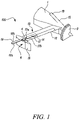
- Figure 1 shows a first embodiment of a lift rotor arrangement 100 for a VTOL aircraft in the extended position.
- the lift rotor arrangement 100 comprises an aerodynamic fairing 6 mounted on the tip of a wing segment 10.
- the fairing 6 comprises a rearward rudder portion 16.
- the lift rotor arrangement also includes a first rotor blade 17 and second rotor blade 18 mounted on a first shaft 4 extending vertically from the fairing 6.
- the first shaft 4 In the extended position when vertical thrust is required for vertical take-off, the first shaft 4 is vertically extended away from the fairing 6 by an electric motor (not shown) housed within the fairing 6.
- the first and second blades 17, 18 are spaced away from the wing segment 10 and are free to rotate with the first shaft 4 about a vertical axis in order to create the vertical thrust.
- the vertical spacing of the first and second blades means they rotate in a plane which is spaced from the wing segment enabling them to rotate freely without risk of colliding with any components of the wing segment 10 or fairing 6.
- An air intake 19 is mounted on top of a body/fuselage 1 to provide an air flow to the main power plant of the aircraft, which may be a hybrid, turbo-electric or fully electric power plant.
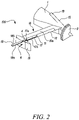
- Figure 2 shows the lift rotor arrangement 100 in the retracted position where the first shaft 4 is retracted into the fairing 6.
- the rotor blades 17, 18 are rotationally-fixed relative to the vertical axis of the shaft with the first rotor blade 17 stowed within a recess 14 (see Figure 1 ) provided in the wing segment 10.
- the first rotor is flush with an upper surface 10a of the wing segment 10 in order to reduce drag during forward cruise driven by a pusher propeller 3.
- the first and second rotor blades 17, 18 are aerofoils and each have a respective leading edge 17a, 18a and trailing edge 17b, 18b. In the retracted position, the trailing edge 17b of the first rotor blade is aligned with the rearward edge 11 of the wing segment 10.
- the first and second rotor blades 17, 18 have an adjustable/variable pitch i.e. they can be rotated around an axis substantially perpendicular to the axis of the first shaft 4. This allows the first and second rotor blades 17, 18 to act as a control surface e.g. as an aileron or elevon in the retracted position to provide attitude control during cruise.
- the wing segment may additionally comprise flaps/elevons 12 to assist in pitch and roll control.
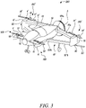
- Figure 3 shows a VTOL aircraft 200 including the lift rotor arrangements 100 in the extended position.
- Figure 4 shows the VTOL aircraft 200 including the lift rotor arrangements 100 in the retracted position.
- the aircraft comprises an aircraft body/fuselage 1 with a nose portion 13 and a tail portion 15.
- the nose portion 13 is provided with two forward lift rotor arrangements 100 substantially as described above in relation to Figures 1 and 2 except that the fairing 6 is rudderless.
- the tail portion 15 is provided with two rearward lift rotor arrangements 100' each comprising a fairing 6' with an extendable and retractable first shaft 4' with first and second rotor blades 17', 18' as described above in Figures 1 and 2 .
- the wing segments 10' in the rearward lift rotor arrangements 100' are box-wing segments having an upper wing portion 101a and a lower wing portion 101b, and the fairings 6' are provided at the joints between the upper and lower wing portions 101a, 101b.
- the upper wing portions 101a are a forward-swept portion and the lower wing portions 101b are swept-back portions.
- each first blade 17' is flush with an upper surface 10a of the upper wing portion 101a.
- FIG. 5 shows an end-on view of the VTOL aircraft 200.
- the fairings 6' on the rearward lift rotor arrangements 100' each further comprise a second shaft 20 with third blades 24 and fourth blades 22 mounted thereon.
- the third blades 24 have a leading edge 24a and a trailing edge (not shown), the leading edge being at the front of the blade in the direction of rotation of the third blade 24, and the trailing edge being at the back of the blade in the direction of rotation.
- the fourth blades 22 have a leading edge (not shown) and a trailing edge (22b), the leading edge being at the front of the blade in the direction of rotation of the fourth blade 22, and the trailing edge 22b being at the back of the blade in the direction of rotation.
- the second shaft 20 is electrically extendable from and retractable within the fairing 6' in an opposing vertical direction to the first shaft 4'.
- the third 24 and fourth blades 22 are spaced away from the wing segment 10' to rotate with the second shaft 20 (in a direction opposite to the rotation of the first and second blades 17', 18') to provide vertical lift.
- the vertical spacing of the third 24 and fourth 22 blades means they rotate in a plane which is spaced from the wing segment enabling them to rotate freely without risk of colliding with any components of the wing segment 10' or fairing 6'.
- the third blade 24 In the retracted position, the third blade 24 is stowed within the lower wing portion 101b of the box wing segment 10', flush with a lower surface 10'b of the lower wing portion 101b. Similar to the first blade 17' and as discussed above in relation to the Figures 1 and 2 , the third blade 24 is an aerofoil and, in the retracted position, the trailing edge of the third rotor blade 24 is stowed in alignment with a rearward edge 11' of the lower wing portion 101b.
- Figure 6 shows a partial top view of the VTOL aircraft 200 with just the rearward lift rotor arrangements 100' (and no blades) shown.
- the insert shows the recess 14' in the upper wing portion 101a of the wing segment 10' with the first blade 17' nested within the recess 14' so as to be flush with the upper surface 10a of the wing segment 10'/upper wing portion 101a.
- Figure 7 shows a partial top view of an alternative embodiment, where the upper wing segment 101a comprises a void 14a.
- the insert shows the void 14a in the upper wing portion 101a of the wing segment 10' with the first blade 17' nested within the recess void 14a to form a portion of the upper wing portion 101a flush with the upper surface 10a' of the wing segment 10'/upper wing portion 101a and a lower surface 10b of the upper wing portion 101a.
- Similar arrangements are possible with the lower wing portion 101b, so that the third blade 24 can be retracted to sit either within a recess or within a void of the lower wing portion.
Claims (14)
- Agencement de rotor de levage (100) pour un aéronef VTOL (200), l'agencement de rotor de levage (100) comprenant : un carénage (6) monté sur un segment d'aile (10) ; et des première et deuxième pales de rotor (17, 18) montées sur un premier arbre (4) s'étendant verticalement à partir du carénage (6), ledit premier arbre (4) étant mobile entre une position étendue dans laquelle les première et deuxième pales de rotor (17, 18) sont espacées verticalement au-dessus du segment d'aile (10) et peuvent tourner pour fournir un levage vertical, et une position escamotée dans laquelle les première et deuxième pales de rotor (17, 18) sont fixées en rotation, la première pale de rotor (17) étant rangée dans le segment d'aile (10), les première et deuxième pales de rotor (17, 18) étant des profils aérodynamiques avec un bord d'attaque (17a, 18a) et un bord de fuite (17b, 18b) respectifs ;
caractérisé en ce que le bord de fuite (17b) de la première pale de rotor (17) est aligné avec un bord arrière (11) du segment d'aile (10) dans la position escamotée. - Agencement de rotor de levage selon la revendication 1, dans la position escamotée, ladite première pale de rotor (17) étant rangée dans un évidement (14) ou un vide (14a) dans le segment d'aile.
- Agencement de rotor de levage selon la revendication 1 ou 2, comprenant en outre des troisième et quatrième pales de rotor (24, 22) montées sur un second arbre (20) s'étendant verticalement à partir du carénage (6') dans une direction verticale opposée au premier arbre (4'), ledit second arbre (20) étant mobile entre une position étendue dans laquelle les troisième et quatrième pales de rotor (24, 22) sont espacées verticalement sous le segment d'aile (10') et peuvent tourner dans une direction opposée aux première et deuxième pales (17', 18'), et une position escamotée dans laquelle les troisième et quatrième pales de rotor (24, 22) sont fixées en rotation avec la troisième pale de rotor rangée dans le segment d'aile (10').
- Agencement de rotor de levage selon la revendication 3, dans la position escamotée, ladite troisième pale de rotor (24) étant rangée à l'intérieur d'un évidement ou d'un vide dans le segment d'aile.
- Agencement de rotor de levage selon l'une quelconque des revendications précédentes, ledit segment d'aile (10) étant une aile en caisson possédant des parties d'aile supérieure et inférieure (101a, 101b) et le carénage (6') étant prévu au niveau du raccord entre les parties d'aile supérieure et inférieure (101a, 101b).
- Agencement de rotor de levage selon la revendication 5, dans la position escamotée, ladite première pale (17) étant rangée à l'intérieur de la partie d'aile supérieure (101a) et ladite troisième pale de rotor (24) étant rangée à l'intérieur de la partie d'aile inférieure (101b).
- Agencement de rotor de levage selon l'une quelconque des revendications 3 à 6, lesdites troisième et quatrième pales de rotor (24, 22) étant des profils aérodynamiques avec un bord d'attaque et un bord de fuite respectifs et ledit bord de fuite de la troisième pale de rotor (24) étant aligné avec un bord arrière (11') du segment d'aile (10') dans la position escamotée.
- Agencement de rotor de levage selon l'une quelconque des revendications précédentes, au moins ladite première pale de rotor (17) pouvant tourner autour d'un axe sensiblement perpendiculaire à l'axe du premier arbre (4) de façon à agir en tant qu'aileron/élevon dans la position escamotée.
- Agencement de rotor de levage selon l'une quelconque des revendications 3 à 8, ladite troisième pale de rotor (24) pouvant tourner autour d'un axe sensiblement perpendiculaire à l'axe du second arbre respectif (20) de façon à agir en tant qu'aileron/élevon dans la position escamotée.
- Aéronef VTOL 200 possédant un corps d'aéronef (1) possédant au moins deux agencements de rotor de levage (100, 100') selon l'une quelconque des revendications 1 à 9 disposés latéralement de chaque côté du corps d'aéronef (1).
- Aéronef VTOL selon la revendication 10, ledit corps d'aéronef comprenant une partie nez avant (13) avec deux agencements de rotor de levage avant (100) disposés latéralement de chaque côté de la partie nez (12).
- Aéronef VTOL selon la revendication 10 ou 11, ledit corps d'aéronef comprenant une partie queue arrière (15) avec deux agencements de rotor de levage arrière (100') disposés latéralement de chaque côté de la partie queue (15).
- Aéronef VTOL selon la revendication 12, lesdits deux agencements de rotor de levage arrière (100') possédant un segment d'aile en caisson avec des parties d'aile supérieure et inférieure (101a, 101b) et lesdits carénages (6') étant prévus au niveau du raccord entre les deux parties d'aile (101a, 101b).
- Aéronef VTOL selon la revendication 12 ou 13, lesdits deux agencements de rotor de levage arrière (100') comprenant un premier arbre (4') avec des première et deuxième pales (17', 18') et un second arbre (20) avec des troisième (24) et quatrième pales (22).
Applications Claiming Priority (2)
| Application Number | Priority Date | Filing Date | Title |
|---|---|---|---|
| GR20190100324 | 2019-07-30 | ||
| GB201913668A GB201913668D0 (en) | 2019-07-30 | 2019-09-23 | Lift rotor system |
Publications (2)
| Publication Number | Publication Date |
|---|---|
| EP3771638A1 EP3771638A1 (fr) | 2021-02-03 |
| EP3771638B1 true EP3771638B1 (fr) | 2022-06-22 |
Family
ID=68425558
Family Applications (1)
| Application Number | Title | Priority Date | Filing Date |
|---|---|---|---|
| EP20187367.6A Active EP3771638B1 (fr) | 2019-07-30 | 2020-07-23 | Système de rotor de levage |
Country Status (3)
| Country | Link |
|---|---|
| US (1) | US11407507B2 (fr) |
| EP (1) | EP3771638B1 (fr) |
| GB (1) | GB201913668D0 (fr) |
Families Citing this family (5)
| Publication number | Priority date | Publication date | Assignee | Title |
|---|---|---|---|---|
| US11440671B2 (en) * | 2019-01-24 | 2022-09-13 | Amazon Technologies, Inc. | Adjustable motor fairings for aerial vehicles |
| US11485490B2 (en) * | 2020-03-27 | 2022-11-01 | Armada Aeronautics, Inc. | System and methods for providing vertical take off and landing and forward flight in a small personal aircraft |
| EP4056471A1 (fr) * | 2021-03-08 | 2022-09-14 | Volocopter GmbH | Aéronef adav |
| US11208206B1 (en) | 2021-05-17 | 2021-12-28 | Beta Air, Llc | Aircraft for fixed pitch lift |
| US20230192290A1 (en) * | 2021-12-17 | 2023-06-22 | Wing Aviation Llc | Uav with augmented lift rotors |
Family Cites Families (12)
| Publication number | Priority date | Publication date | Assignee | Title |
|---|---|---|---|---|
| US4789115A (en) | 1986-08-29 | 1988-12-06 | Theodore Koutsoupidis | VTOL aircraft |
| US6622962B1 (en) | 2002-04-29 | 2003-09-23 | Bruce D. White | Fixed wing aircraft having powered rotor VTOL capability with rotor blades stowable during horizontal flight |
| US8052081B2 (en) | 2008-08-22 | 2011-11-08 | Draganfly Innovations Inc. | Dual rotor helicopter with tilted rotational axes |
| US8376264B1 (en) | 2009-08-24 | 2013-02-19 | Jianhui Hong | Rotor for a dual mode aircraft |
| US9527581B2 (en) | 2013-07-25 | 2016-12-27 | Joby Aviation, Inc. | Aerodynamically efficient lightweight vertical take-off and landing aircraft with multi-configuration wing tip mounted rotors |
| DE102013109392A1 (de) * | 2013-08-29 | 2015-03-05 | Airbus Defence and Space GmbH | Schnellfliegendes, senkrechtstartfähiges Fluggerät |
| WO2015200345A1 (fr) | 2014-06-24 | 2015-12-30 | Oliver Garreau | Aéronef à cinq voilures pour permettre des transitions douces entre le vol vertical et horizontal |
| US20160244147A1 (en) | 2015-02-20 | 2016-08-25 | Northrop Grumman Systems Corporation | Quiet slat propeller |
| CN205311899U (zh) * | 2015-12-25 | 2016-06-15 | 广州亿航智能技术有限公司 | 多旋翼载人飞行器 |
| US10167080B2 (en) | 2016-09-19 | 2019-01-01 | Bell Helicopter Textron Inc. | Storage modes for tiltrotor aircraft |
| US10336443B2 (en) * | 2017-06-19 | 2019-07-02 | Bell Helicopter Textron Inc. | Retractable and deployable flight rotor system |
| EP3702276B1 (fr) * | 2019-02-27 | 2021-01-13 | AIRBUS HELICOPTERS DEUTSCHLAND GmbH | Aéronef multirotor à aile jointe avec des capacités de décollage et atterrissage verticaux (adav) |
-
2019
- 2019-09-23 GB GB201913668A patent/GB201913668D0/en not_active Ceased
-
2020
- 2020-07-15 US US16/930,008 patent/US11407507B2/en active Active
- 2020-07-23 EP EP20187367.6A patent/EP3771638B1/fr active Active
Also Published As
| Publication number | Publication date |
|---|---|
| US11407507B2 (en) | 2022-08-09 |
| US20210031909A1 (en) | 2021-02-04 |
| EP3771638A1 (fr) | 2021-02-03 |
| GB201913668D0 (en) | 2019-11-06 |
Similar Documents
| Publication | Publication Date | Title |
|---|---|---|
| EP3771638B1 (fr) | Système de rotor de levage | |
| JP6949869B2 (ja) | テイルシッター航空機用回転翼アセンブリ | |
| US10556679B2 (en) | Vertical takeoff and landing airframe | |
| US10131424B2 (en) | Compound rotorcraft | |
| US6659394B1 (en) | Compound tilting wing for high lift stability and control of aircraft | |
| JP4469081B2 (ja) | 航空機の改良 | |
| EP2690011B1 (fr) | Hélicoptère combiné | |
| US8387913B2 (en) | Compact aircraft wing folding systems and methods | |
| EP2690012A1 (fr) | Giravion semi-convertible | |
| WO2020243364A2 (fr) | Nouvelle conception d'aéronef utilisant des ailes en tandem et un système de propulsion réparti | |
| CN111619795A (zh) | 能垂直起飞和降落的联结翼的多旋翼飞行器 | |
| CN103158856B (zh) | 可短距起降的轻型螺旋桨飞翼飞机 | |
| KR20220029575A (ko) | 강성 날개 공기역학을 시뮬레이션하기 위해 고정된 전방으로 기울어진 회전자를 사용하는 수직 이착륙 항공기 | |
| US11873086B2 (en) | Variable-sweep wing aerial vehicle with VTOL capabilites | |
| CN115489716B (zh) | 集成有分布式涵道风扇的机翼和电动飞机 | |
| US8262017B2 (en) | Aircraft with forward lifting elevator and rudder, with the main lifting surface aft, containing ailerons and flaps, and airbrake | |
| WO2023034302A1 (fr) | Système et procédé d'hypersustentation de portance d'ailes d'aéronef | |
| WO2022139623A1 (fr) | Automate de rotulage d'aéronef à rotors multiples avec fixation rigide des pales et procédé de fonctionnement | |
| CN213323678U (zh) | 一种动力分配型式的可垂直起降无人飞行器 | |
| WO2022053984A1 (fr) | Aéronef à voilure tournante à décollage et atterrissage verticaux | |
| EP4008628B1 (fr) | Girodyne à ailes contreventées et en configuration à ailes jointes | |
| RU222496U1 (ru) | Беспилотный летательный аппарат вертикального взлета и посадки | |
| CN219192548U (zh) | 一种v尾单推电动垂直起降复合翼飞行器 | |
| WO2023051013A1 (fr) | Aéronef à décollage et atterrissage verticaux basé sur une technologie de voilure à hélice variable et agencement à double voilure à hélice | |
| CN214493337U (zh) | 一种融合式旋翼/固定翼无人飞行器 |
Legal Events
| Date | Code | Title | Description |
|---|---|---|---|
| PUAI | Public reference made under article 153(3) epc to a published international application that has entered the european phase |
Free format text: ORIGINAL CODE: 0009012 |
|
| STAA | Information on the status of an ep patent application or granted ep patent |
Free format text: STATUS: THE APPLICATION HAS BEEN PUBLISHED |
|
| AK | Designated contracting states |
Kind code of ref document: A1 Designated state(s): AL AT BE BG CH CY CZ DE DK EE ES FI FR GB GR HR HU IE IS IT LI LT LU LV MC MK MT NL NO PL PT RO RS SE SI SK SM TR |
|
| AX | Request for extension of the european patent |
Extension state: BA ME |
|
| STAA | Information on the status of an ep patent application or granted ep patent |
Free format text: STATUS: REQUEST FOR EXAMINATION WAS MADE |
|
| 17P | Request for examination filed |
Effective date: 20210729 |
|
| RBV | Designated contracting states (corrected) |
Designated state(s): AL AT BE BG CH CY CZ DE DK EE ES FI FR GB GR HR HU IE IS IT LI LT LU LV MC MK MT NL NO PL PT RO RS SE SI SK SM TR |
|
| GRAP | Despatch of communication of intention to grant a patent |
Free format text: ORIGINAL CODE: EPIDOSNIGR1 |
|
| STAA | Information on the status of an ep patent application or granted ep patent |
Free format text: STATUS: GRANT OF PATENT IS INTENDED |
|
| RIC1 | Information provided on ipc code assigned before grant |
Ipc: B64C 11/28 20060101ALN20220406BHEP Ipc: B64C 9/00 20060101ALN20220406BHEP Ipc: B64C 11/30 20060101ALN20220406BHEP Ipc: B64C 39/12 20060101ALI20220406BHEP Ipc: B64C 7/00 20060101ALI20220406BHEP Ipc: B64C 27/26 20060101ALI20220406BHEP Ipc: B64C 27/02 20060101ALI20220406BHEP Ipc: B64C 39/06 20060101ALI20220406BHEP Ipc: B64C 29/00 20060101AFI20220406BHEP |
|
| GRAS | Grant fee paid |
Free format text: ORIGINAL CODE: EPIDOSNIGR3 |
|
| GRAA | (expected) grant |
Free format text: ORIGINAL CODE: 0009210 |
|
| STAA | Information on the status of an ep patent application or granted ep patent |
Free format text: STATUS: THE PATENT HAS BEEN GRANTED |
|
| INTG | Intention to grant announced |
Effective date: 20220429 |
|
| AK | Designated contracting states |
Kind code of ref document: B1 Designated state(s): AL AT BE BG CH CY CZ DE DK EE ES FI FR GB GR HR HU IE IS IT LI LT LU LV MC MK MT NL NO PL PT RO RS SE SI SK SM TR |
|
| REG | Reference to a national code |
Ref country code: GB Ref legal event code: FG4D |
|
| REG | Reference to a national code |
Ref country code: CH Ref legal event code: EP |
|
| REG | Reference to a national code |
Ref country code: DE Ref legal event code: R096 Ref document number: 602020003639 Country of ref document: DE |
|
| REG | Reference to a national code |
Ref country code: AT Ref legal event code: REF Ref document number: 1499633 Country of ref document: AT Kind code of ref document: T Effective date: 20220715 |
|
| REG | Reference to a national code |
Ref country code: IE Ref legal event code: FG4D |
|
| REG | Reference to a national code |
Ref country code: LT Ref legal event code: MG9D |
|
| REG | Reference to a national code |
Ref country code: NL Ref legal event code: MP Effective date: 20220622 |
|
| PG25 | Lapsed in a contracting state [announced via postgrant information from national office to epo] |
Ref country code: SE Free format text: LAPSE BECAUSE OF FAILURE TO SUBMIT A TRANSLATION OF THE DESCRIPTION OR TO PAY THE FEE WITHIN THE PRESCRIBED TIME-LIMIT Effective date: 20220622 Ref country code: NO Free format text: LAPSE BECAUSE OF FAILURE TO SUBMIT A TRANSLATION OF THE DESCRIPTION OR TO PAY THE FEE WITHIN THE PRESCRIBED TIME-LIMIT Effective date: 20220922 Ref country code: LT Free format text: LAPSE BECAUSE OF FAILURE TO SUBMIT A TRANSLATION OF THE DESCRIPTION OR TO PAY THE FEE WITHIN THE PRESCRIBED TIME-LIMIT Effective date: 20220622 Ref country code: HR Free format text: LAPSE BECAUSE OF FAILURE TO SUBMIT A TRANSLATION OF THE DESCRIPTION OR TO PAY THE FEE WITHIN THE PRESCRIBED TIME-LIMIT Effective date: 20220622 Ref country code: GR Free format text: LAPSE BECAUSE OF FAILURE TO SUBMIT A TRANSLATION OF THE DESCRIPTION OR TO PAY THE FEE WITHIN THE PRESCRIBED TIME-LIMIT Effective date: 20220923 Ref country code: FI Free format text: LAPSE BECAUSE OF FAILURE TO SUBMIT A TRANSLATION OF THE DESCRIPTION OR TO PAY THE FEE WITHIN THE PRESCRIBED TIME-LIMIT Effective date: 20220622 Ref country code: BG Free format text: LAPSE BECAUSE OF FAILURE TO SUBMIT A TRANSLATION OF THE DESCRIPTION OR TO PAY THE FEE WITHIN THE PRESCRIBED TIME-LIMIT Effective date: 20220922 |
|
| REG | Reference to a national code |
Ref country code: AT Ref legal event code: MK05 Ref document number: 1499633 Country of ref document: AT Kind code of ref document: T Effective date: 20220622 |
|
| PG25 | Lapsed in a contracting state [announced via postgrant information from national office to epo] |
Ref country code: RS Free format text: LAPSE BECAUSE OF FAILURE TO SUBMIT A TRANSLATION OF THE DESCRIPTION OR TO PAY THE FEE WITHIN THE PRESCRIBED TIME-LIMIT Effective date: 20220622 Ref country code: LV Free format text: LAPSE BECAUSE OF FAILURE TO SUBMIT A TRANSLATION OF THE DESCRIPTION OR TO PAY THE FEE WITHIN THE PRESCRIBED TIME-LIMIT Effective date: 20220622 |
|
| PG25 | Lapsed in a contracting state [announced via postgrant information from national office to epo] |
Ref country code: NL Free format text: LAPSE BECAUSE OF FAILURE TO SUBMIT A TRANSLATION OF THE DESCRIPTION OR TO PAY THE FEE WITHIN THE PRESCRIBED TIME-LIMIT Effective date: 20220622 |
|
| PG25 | Lapsed in a contracting state [announced via postgrant information from national office to epo] |
Ref country code: SM Free format text: LAPSE BECAUSE OF FAILURE TO SUBMIT A TRANSLATION OF THE DESCRIPTION OR TO PAY THE FEE WITHIN THE PRESCRIBED TIME-LIMIT Effective date: 20220622 Ref country code: SK Free format text: LAPSE BECAUSE OF FAILURE TO SUBMIT A TRANSLATION OF THE DESCRIPTION OR TO PAY THE FEE WITHIN THE PRESCRIBED TIME-LIMIT Effective date: 20220622 Ref country code: RO Free format text: LAPSE BECAUSE OF FAILURE TO SUBMIT A TRANSLATION OF THE DESCRIPTION OR TO PAY THE FEE WITHIN THE PRESCRIBED TIME-LIMIT Effective date: 20220622 Ref country code: PT Free format text: LAPSE BECAUSE OF FAILURE TO SUBMIT A TRANSLATION OF THE DESCRIPTION OR TO PAY THE FEE WITHIN THE PRESCRIBED TIME-LIMIT Effective date: 20221024 Ref country code: ES Free format text: LAPSE BECAUSE OF FAILURE TO SUBMIT A TRANSLATION OF THE DESCRIPTION OR TO PAY THE FEE WITHIN THE PRESCRIBED TIME-LIMIT Effective date: 20220622 Ref country code: EE Free format text: LAPSE BECAUSE OF FAILURE TO SUBMIT A TRANSLATION OF THE DESCRIPTION OR TO PAY THE FEE WITHIN THE PRESCRIBED TIME-LIMIT Effective date: 20220622 Ref country code: CZ Free format text: LAPSE BECAUSE OF FAILURE TO SUBMIT A TRANSLATION OF THE DESCRIPTION OR TO PAY THE FEE WITHIN THE PRESCRIBED TIME-LIMIT Effective date: 20220622 Ref country code: AT Free format text: LAPSE BECAUSE OF FAILURE TO SUBMIT A TRANSLATION OF THE DESCRIPTION OR TO PAY THE FEE WITHIN THE PRESCRIBED TIME-LIMIT Effective date: 20220622 |
|
| PG25 | Lapsed in a contracting state [announced via postgrant information from national office to epo] |
Ref country code: PL Free format text: LAPSE BECAUSE OF FAILURE TO SUBMIT A TRANSLATION OF THE DESCRIPTION OR TO PAY THE FEE WITHIN THE PRESCRIBED TIME-LIMIT Effective date: 20220622 Ref country code: IS Free format text: LAPSE BECAUSE OF FAILURE TO SUBMIT A TRANSLATION OF THE DESCRIPTION OR TO PAY THE FEE WITHIN THE PRESCRIBED TIME-LIMIT Effective date: 20221022 |
|
| REG | Reference to a national code |
Ref country code: DE Ref legal event code: R097 Ref document number: 602020003639 Country of ref document: DE |
|
| REG | Reference to a national code |
Ref country code: BE Ref legal event code: MM Effective date: 20220731 |
|
| PG25 | Lapsed in a contracting state [announced via postgrant information from national office to epo] |
Ref country code: MC Free format text: LAPSE BECAUSE OF FAILURE TO SUBMIT A TRANSLATION OF THE DESCRIPTION OR TO PAY THE FEE WITHIN THE PRESCRIBED TIME-LIMIT Effective date: 20220622 Ref country code: AL Free format text: LAPSE BECAUSE OF FAILURE TO SUBMIT A TRANSLATION OF THE DESCRIPTION OR TO PAY THE FEE WITHIN THE PRESCRIBED TIME-LIMIT Effective date: 20220622 |
|
| PG25 | Lapsed in a contracting state [announced via postgrant information from national office to epo] |
Ref country code: LU Free format text: LAPSE BECAUSE OF NON-PAYMENT OF DUE FEES Effective date: 20220723 Ref country code: DK Free format text: LAPSE BECAUSE OF FAILURE TO SUBMIT A TRANSLATION OF THE DESCRIPTION OR TO PAY THE FEE WITHIN THE PRESCRIBED TIME-LIMIT Effective date: 20220622 |
|
| PLBE | No opposition filed within time limit |
Free format text: ORIGINAL CODE: 0009261 |
|
| STAA | Information on the status of an ep patent application or granted ep patent |
Free format text: STATUS: NO OPPOSITION FILED WITHIN TIME LIMIT |
|
| 26N | No opposition filed |
Effective date: 20230323 |
|
| PG25 | Lapsed in a contracting state [announced via postgrant information from national office to epo] |
Ref country code: BE Free format text: LAPSE BECAUSE OF NON-PAYMENT OF DUE FEES Effective date: 20220731 |
|
| P01 | Opt-out of the competence of the unified patent court (upc) registered |
Effective date: 20230528 |
|
| PG25 | Lapsed in a contracting state [announced via postgrant information from national office to epo] |
Ref country code: IE Free format text: LAPSE BECAUSE OF NON-PAYMENT OF DUE FEES Effective date: 20220723 |
|
| PG25 | Lapsed in a contracting state [announced via postgrant information from national office to epo] |
Ref country code: SI Free format text: LAPSE BECAUSE OF FAILURE TO SUBMIT A TRANSLATION OF THE DESCRIPTION OR TO PAY THE FEE WITHIN THE PRESCRIBED TIME-LIMIT Effective date: 20220622 |
|
| PGFP | Annual fee paid to national office [announced via postgrant information from national office to epo] |
Ref country code: FR Payment date: 20230725 Year of fee payment: 4 Ref country code: DE Payment date: 20230726 Year of fee payment: 4 |
|
| PG25 | Lapsed in a contracting state [announced via postgrant information from national office to epo] |
Ref country code: IT Free format text: LAPSE BECAUSE OF FAILURE TO SUBMIT A TRANSLATION OF THE DESCRIPTION OR TO PAY THE FEE WITHIN THE PRESCRIBED TIME-LIMIT Effective date: 20220622 |
|
| REG | Reference to a national code |
Ref country code: CH Ref legal event code: PL |