EP3141478B1 - Compound helicopter - Google Patents
Compound helicopter Download PDFInfo
- Publication number
- EP3141478B1 EP3141478B1 EP15400040.0A EP15400040A EP3141478B1 EP 3141478 B1 EP3141478 B1 EP 3141478B1 EP 15400040 A EP15400040 A EP 15400040A EP 3141478 B1 EP3141478 B1 EP 3141478B1
- Authority
- EP
- European Patent Office
- Prior art keywords
- wing
- compound helicopter
- fuselage
- section
- helicopter
- Prior art date
- Legal status (The legal status is an assumption and is not a legal conclusion. Google has not performed a legal analysis and makes no representation as to the accuracy of the status listed.)
- Active
Links
- 150000001875 compounds Chemical class 0.000 title claims description 119
- 230000010354 integration Effects 0.000 description 7
- 238000013329 compounding Methods 0.000 description 4
- 230000005484 gravity Effects 0.000 description 4
- 230000007704 transition Effects 0.000 description 4
- 238000005452 bending Methods 0.000 description 2
- 230000008901 benefit Effects 0.000 description 2
- 238000000926 separation method Methods 0.000 description 2
- 239000003381 stabilizer Substances 0.000 description 2
- 238000011144 upstream manufacturing Methods 0.000 description 2
- 241000272517 Anseriformes Species 0.000 description 1
- 230000007812 deficiency Effects 0.000 description 1
- 230000002349 favourable effect Effects 0.000 description 1
- 230000000873 masking effect Effects 0.000 description 1
- 238000012986 modification Methods 0.000 description 1
- 230000004048 modification Effects 0.000 description 1
- 230000001141 propulsive effect Effects 0.000 description 1
- 230000006641 stabilisation Effects 0.000 description 1
- 238000011105 stabilization Methods 0.000 description 1
- 230000002195 synergetic effect Effects 0.000 description 1
- 239000013585 weight reducing agent Substances 0.000 description 1
Images


Classifications
-
- B—PERFORMING OPERATIONS; TRANSPORTING
- B64—AIRCRAFT; AVIATION; COSMONAUTICS
- B64C—AEROPLANES; HELICOPTERS
- B64C27/00—Rotorcraft; Rotors peculiar thereto
- B64C27/22—Compound rotorcraft, i.e. aircraft using in flight the features of both aeroplane and rotorcraft
- B64C27/26—Compound rotorcraft, i.e. aircraft using in flight the features of both aeroplane and rotorcraft characterised by provision of fixed wings
-
- B—PERFORMING OPERATIONS; TRANSPORTING
- B64—AIRCRAFT; AVIATION; COSMONAUTICS
- B64C—AEROPLANES; HELICOPTERS
- B64C1/00—Fuselages; Constructional features common to fuselages, wings, stabilising surfaces or the like
- B64C1/26—Attaching the wing or tail units or stabilising surfaces
-
- B—PERFORMING OPERATIONS; TRANSPORTING
- B64—AIRCRAFT; AVIATION; COSMONAUTICS
- B64C—AEROPLANES; HELICOPTERS
- B64C25/00—Alighting gear
- B64C25/02—Undercarriages
- B64C25/08—Undercarriages non-fixed, e.g. jettisonable
- B64C25/10—Undercarriages non-fixed, e.g. jettisonable retractable, foldable, or the like
-
- B—PERFORMING OPERATIONS; TRANSPORTING
- B64—AIRCRAFT; AVIATION; COSMONAUTICS
- B64C—AEROPLANES; HELICOPTERS
- B64C25/00—Alighting gear
- B64C25/32—Alighting gear characterised by elements which contact the ground or similar surface
- B64C25/34—Alighting gear characterised by elements which contact the ground or similar surface wheeled type, e.g. multi-wheeled bogies
-
- B—PERFORMING OPERATIONS; TRANSPORTING
- B64—AIRCRAFT; AVIATION; COSMONAUTICS
- B64C—AEROPLANES; HELICOPTERS
- B64C27/00—Rotorcraft; Rotors peculiar thereto
- B64C27/02—Gyroplanes
- B64C27/028—Other constructional elements; Rotor balancing
-
- B—PERFORMING OPERATIONS; TRANSPORTING
- B64—AIRCRAFT; AVIATION; COSMONAUTICS
- B64C—AEROPLANES; HELICOPTERS
- B64C27/00—Rotorcraft; Rotors peculiar thereto
- B64C27/04—Helicopters
- B64C27/06—Helicopters with single rotor
-
- B—PERFORMING OPERATIONS; TRANSPORTING
- B64—AIRCRAFT; AVIATION; COSMONAUTICS
- B64C—AEROPLANES; HELICOPTERS
- B64C27/00—Rotorcraft; Rotors peculiar thereto
- B64C27/22—Compound rotorcraft, i.e. aircraft using in flight the features of both aeroplane and rotorcraft
- B64C27/24—Compound rotorcraft, i.e. aircraft using in flight the features of both aeroplane and rotorcraft with rotor blades fixed in flight to act as lifting surfaces
-
- B—PERFORMING OPERATIONS; TRANSPORTING
- B64—AIRCRAFT; AVIATION; COSMONAUTICS
- B64C—AEROPLANES; HELICOPTERS
- B64C27/00—Rotorcraft; Rotors peculiar thereto
- B64C27/22—Compound rotorcraft, i.e. aircraft using in flight the features of both aeroplane and rotorcraft
- B64C27/28—Compound rotorcraft, i.e. aircraft using in flight the features of both aeroplane and rotorcraft with forward-propulsion propellers pivotable to act as lifting rotors
-
- B—PERFORMING OPERATIONS; TRANSPORTING
- B64—AIRCRAFT; AVIATION; COSMONAUTICS
- B64C—AEROPLANES; HELICOPTERS
- B64C27/00—Rotorcraft; Rotors peculiar thereto
- B64C27/82—Rotorcraft; Rotors peculiar thereto characterised by the provision of an auxiliary rotor or fluid-jet device for counter-balancing lifting rotor torque or changing direction of rotorcraft
-
- B—PERFORMING OPERATIONS; TRANSPORTING
- B64—AIRCRAFT; AVIATION; COSMONAUTICS
- B64C—AEROPLANES; HELICOPTERS
- B64C3/00—Wings
- B64C3/10—Shape of wings
- B64C3/16—Frontal aspect
-
- B—PERFORMING OPERATIONS; TRANSPORTING
- B64—AIRCRAFT; AVIATION; COSMONAUTICS
- B64C—AEROPLANES; HELICOPTERS
- B64C3/00—Wings
- B64C3/18—Spars; Ribs; Stringers
- B64C3/185—Spars
-
- B—PERFORMING OPERATIONS; TRANSPORTING
- B64—AIRCRAFT; AVIATION; COSMONAUTICS
- B64C—AEROPLANES; HELICOPTERS
- B64C39/00—Aircraft not otherwise provided for
- B64C39/06—Aircraft not otherwise provided for having disc- or ring-shaped wings
- B64C39/068—Aircraft not otherwise provided for having disc- or ring-shaped wings having multiple wings joined at the tips
-
- B—PERFORMING OPERATIONS; TRANSPORTING
- B64—AIRCRAFT; AVIATION; COSMONAUTICS
- B64C—AEROPLANES; HELICOPTERS
- B64C25/00—Alighting gear
- B64C25/32—Alighting gear characterised by elements which contact the ground or similar surface
- B64C2025/325—Alighting gear characterised by elements which contact the ground or similar surface specially adapted for helicopters
-
- B—PERFORMING OPERATIONS; TRANSPORTING
- B64—AIRCRAFT; AVIATION; COSMONAUTICS
- B64C—AEROPLANES; HELICOPTERS
- B64C27/00—Rotorcraft; Rotors peculiar thereto
- B64C27/82—Rotorcraft; Rotors peculiar thereto characterised by the provision of an auxiliary rotor or fluid-jet device for counter-balancing lifting rotor torque or changing direction of rotorcraft
- B64C2027/8236—Rotorcraft; Rotors peculiar thereto characterised by the provision of an auxiliary rotor or fluid-jet device for counter-balancing lifting rotor torque or changing direction of rotorcraft including pusher propellers
-
- B—PERFORMING OPERATIONS; TRANSPORTING
- B64—AIRCRAFT; AVIATION; COSMONAUTICS
- B64C—AEROPLANES; HELICOPTERS
- B64C27/00—Rotorcraft; Rotors peculiar thereto
- B64C27/82—Rotorcraft; Rotors peculiar thereto characterised by the provision of an auxiliary rotor or fluid-jet device for counter-balancing lifting rotor torque or changing direction of rotorcraft
- B64C2027/8263—Rotorcraft; Rotors peculiar thereto characterised by the provision of an auxiliary rotor or fluid-jet device for counter-balancing lifting rotor torque or changing direction of rotorcraft comprising in addition rudders, tails, fins, or the like
-
- Y—GENERAL TAGGING OF NEW TECHNOLOGICAL DEVELOPMENTS; GENERAL TAGGING OF CROSS-SECTIONAL TECHNOLOGIES SPANNING OVER SEVERAL SECTIONS OF THE IPC; TECHNICAL SUBJECTS COVERED BY FORMER USPC CROSS-REFERENCE ART COLLECTIONS [XRACs] AND DIGESTS
- Y02—TECHNOLOGIES OR APPLICATIONS FOR MITIGATION OR ADAPTATION AGAINST CLIMATE CHANGE
- Y02T—CLIMATE CHANGE MITIGATION TECHNOLOGIES RELATED TO TRANSPORTATION
- Y02T50/00—Aeronautics or air transport
- Y02T50/10—Drag reduction
Definitions
- the invention is related to a compound helicopter with a fuselage, at least one main rotor that is at least adapted for generating lift in operation, and a fixed wing arrangement that is laterally attached to the fuselage, said compound helicopter comprising the features of claim 1.
- Compound helicopters and so-called convertiplanes are basically the most relevant concepts aiming to overcome horizontal flight deficiencies of conventional helicopters, i. e. helicopters with a main rotor and an auxiliary tail rotor that is adapted to counter torque, by introducing attributes of fixed-wing aircrafts to such conventional helicopters as compromise.
- a compromise between both aircraft types has always to be conveniently adapted to a planned mission profile of a given helicopter.
- An exemplary convertiplane is e. g. described in the document US 5,046,684 A . More specifically, the latter describes a tiltrotor aircraft with a fuselage and a fixed wing arrangement. On each side of the fuselage a first and a second wing are arranged. The first wing is fixed at substantially the bottom of the fuselage and substantially unperforated in hovering as well as forward flight. The second wing is fixed at substantially the top of the fuselage, or fixed to a structure extending above the fuselage, and is likewise substantially unperforated in hovering as well as forward flight. At least one of the first and second wings has dihedral so that the wings converge to join or nearly join at their tips.
- winged compound helicopter configurations with separate propulsion units typically feature a monoplane design with one set of wing surfaces in cantilever design as shoulder-wing arrangement.
- a compound helicopter with lift compounding, thrust compounding or a combination of both basically aims to off-load a respective main rotor from its simultaneous lifting and propulsive duties to allow for higher forward speeds of the compound helicopter.
- lift compounding entails adding wings to a helicopter, hence enabling to increase an underlying load factor of the helicopter and to reach a higher maneuverability. This improves the efficiency of the helicopter at moderately high speed but at the expense of reduced efficiencies at lower forward speeds and in the hover.
- a more extended configuration of a compound helicopter includes both the addition of wings and propulsion units.
- lift during cruise is simultaneously provided by a given main rotor - in powered condition - usually addressed as “hybrid helicopter” - or in autorotation - "autogyro" - modus - and the wings.
- Higher forward speed is provided by horizontally oriented auxiliary propulsion units of the compound helicopter.
- the compound helicopter hence overcomes underlying rotor lift limits by means of the wings and underlying rotor thrust limits by means of the propulsion units.
- a higher load factor is obtained along with potential for higher speed.
- use of a pair of thrust propulsion units - opposed and both offset relative to each other and to a longitudinal axis of the compound helicopter - enables for a simultaneous torque correction.
- Exemplary compound helicopters with two wing-mounted propellers defining the above-described propulsion units are described in the documents EP 2 146 896 A1 , EP 2 690 011 A1 and US 2013/0175385 A1 . These exemplary compound helicopters are all provided with fixed wing arrangements, as described hereinafter.
- the document EP2690011 describes a compound helicopter with a fixed wing arrangement in the form of a joined-wing configuration, wherein a lower wing and an upper wing are provided on each side of the compound helicopter. Both wings are essentially straight and interconnected to each other at a wing interconnection region, and a pusher propeller is installed in the interconnection region behind associated trailing edges of both wings.
- This joined-wing configuration especially outstands by its improved mechanical efficiency in terms of less structural weight and larger stiffness, as well as by improved inherent operational safety characteristics and improved system integration, especially referring to an underlying accessibility of a main gear box of the compound helicopter.
- the document EP2418148 describes an airliner aircraft having a lambda-box wing configuration.
- the aircraft comprises a fuselage, a propulsion system with turbojets, a first pair of swept-back airfoils, connected to the top forward portion of the fuselage.
- a second pair of swept-forward airfoils is connected to the lower rear portion of the fuselage at a point of the fuselage aft of the connection of the swept-back airfoils.
- a third pair of substantially vertical airfoils is provided between the tips of the swept-forward airfoils and the lower side of the swept-back airfoils.
- the propulsion system has one engine mounted in the extension middle of each of the first swept-back airfoils, either directly or on top of a further stand.
- the swept-back airfoils extend with an outwardly upwards angle with respect to the horizontal plane.
- the second pair of swept-forward airfoils are simply shaped.
- the document US4856736 describes an aircraft having paired aerofoils where wing tips are joined in the same plane one behind the other. The trailing edge of the forward wings and the leading edge of the rearward wings is coincidental in plan view at the wing tip.
- a single propeller is mounted at a front end of the fuselage in an embodiment.
- a pair of propellers is mounted at a front end of the fuselage, each on a canard pole, in another embodiment.
- the document US8657226 describes synergistic control enhancement and drag reduction benefits in an aircraft having independent airfoils producing downward force opposite to wing lift in normal flight.
- the airfoils are supported in specific wingtip locations.
- the aircraft is of fixed wing type, with propellers mounted on the fuselage, on poles in some embodiments.
- the document US20130175383 describes another compound helicopter with fixed wing arrangement in the form of a joined-wing configuration having lower and upper wings that are each parallel to a given pitch axis of the compound helicopter.
- the wings exhibit a constant dihedral and the upper wings entirely cover the lower wings so as to minimize down-wash drag. This translates to a design with same depth of the wings, same wing orientation, and same position of attachment of the upper and lower wings.
- a compound helicopter with a fuselage, at least one main rotor that is at least adapted for generating lift in operation, and a fixed wing arrangement that is laterally attached to the fuselage, said compound helicopter comprising the features of claim 1.
- a compound helicopter with a fuselage and at least one main rotor that is at least adapted for generating lift in operation is provided.
- the fuselage comprises a lower side and an upper side that is opposed to the lower side.
- the at least one main rotor is arranged at the upper side.
- At least one propeller is provided that is at least adapted for generating forward thrust in operation, the at least one propeller being mounted to a fixed wing arrangement that is laterally attached to the fuselage.
- the fixed wing arrangement comprises at least one upper wing that is arranged at an upper wing root joint area provided at the upper side of the fuselage and at least one lower wing that is arranged at a lower wing root joint area provided at the lower side of the fuselage.
- the upper and lower wings are at least interconnected at an associated interconnection region.
- Each of the at least one propeller is mounted to an associated interconnection region and the compound helicopter is provided with a wheel-type main landing gear.
- the lower wing comprises an inboard section defining a first quarter chord line and a first centroidal axis and an outboard section defining a second quarter chord line and a second centroidal axis.
- the inboard section is an integral part of the fuselage at the lower wing root joint area and connected to the outboard section at a sections interconnection region.
- the wheel-type main landing gear is mounted to said inboard section adjacent to said sections interconnection region.
- the outboard section is connected to the inboard section at the sections interconnection region and to the upper wing at the associated interconnection region.
- the second centroidal axis is inclined relative to the first centroidal axis by a relative dihedral angle that is defined in a first coordinate plane.
- the second quarter chord line is inclined relative to the first quarter chord line by a relative sweep angle that is defined in a second coordinate plane.
- the compound helicopter according to the present invention comprises a specific arrangement and planform of an underlying bi-plane wing structure on each side of the compound helicopter, with a main rotor providing lift and a pair of additional propulsion devices, i.e. propellers, providing thrust.
- the bi-plane wing structure on each side of the compound helicopter provides additional lift during horizontal cruise flight.
- the additional propulsion devices are arranged on the underlying bi-plane wing structure at the intersections of respective wings, preferentially one at each side of the compound helicopter.
- the inventive compound helicopter preferably comprises a new joined-wing configuration with a new wing planform.
- the new wing planform uses a unique shape and layout of a given lower wing featuring a simultaneous "polyhedral" and "multi-sweep" design.
- polyhedral addresses use of two different wing portions with two different dihedral angles
- multi-sweep addresses use of two different wing portions with two different sweep angles.
- the dihedral angle is defined as an angle of the centroidal axis of the wing with respect to the horizontal Y-axis, i. e. pitch axis, of the compound helicopter and basically represents an inclination of the wing in a front view plane of the compound helicopter with respect to a horizontal plane.
- the sweep angle is defined as an angle between the quarter chord line of the wing and a transverse Y-axis of the helicopter, the quarter chord line being the line which spans 25% of the wing chord.
- the lower wing is, hence, characterized by a cranked layout with one inboard section and one outboard section, both featuring different dihedral and sweep angles.
- reduction of the dihedral angle of the lower wing at its root region improves an underlying aerodynamic efficiency of a given wing-fuselage transition. Furthermore, reduction of the sweep angle at the inboard wing section allows keeping its rear main spar away from a predefined propeller burst cone and allows for a clean transition layout from the lower wing's trailing edge to the intermediate compound helicopter structure.
- the inboard section of the lower wing preferably exhibits a lower dihedral angle and lower sweep angle in comparison to the outboard section.
- An almost un-swept inboard section with a low sweep angle, essentially perpendicular to the longitudinal axis of the compound helicopter, is advantageous with respect to main landing gear integration and to a resulting aerodynamic center of lift.
- Main landing gear integration with standard kinematics preferably requires perpendicular support elements at each side of the main landing gear, which are conveniently provided by the two spars of the inboard section.
- An underlying aerodynamic center of lift should not exceed a specific longitudinal distance from an underlying center of gravity in order to maintain adequate aerodynamic balance at high-speed operation of the compound helicopter.
- a main landing gear is attached to the lower wing at its kink region, i. e. a transition region of the inboard section of the lower wing to the outboard section of the lower wing, and at least partially housed, in its retracted position, within the inboard section.
- the kink region separates the inboard section from the outboard section and is preferably, a structural releasable joint that allows an easy separation of both lower wing sections from each other.
- separation of the lower wing into an inboard section and an outboard section allows for a structural integration of the inboard section and the main landing gear to the fuselage.
- a disassembly of the lower wing and/or the lower and upper wings does not involve a removal of the main landing gear from the fuselage.
- the inventive compound helicopter is able to stay on its own supports.
- the inboard section is preferably a structural part of the fuselage which integrates the main landing gear attachment points.
- the attachment of the inboard section to the outboard section can either be hinged or clamped.
- a purely hinged joint has fewer interconnections and lesser associated assembly tolerance issues.
- a dihedral kink introduces in a load scenario with large down loads a transverse load and bending load component which counteracts - at least to a certain extent - respective reaction loads of the main landing gear.
- an underlying stress state of respective main load carrying r members of the inboard section and its structural interconnection to the fuselage can be alleviated.
- the dihedral kink provides for a roughly 10% larger airfoil thickness of the inboard section of the lower wing in comparison to the outboard section, hence providing for additional available volume for the main landing gear introduction without a need for increasing or tapering the thickness of the outboard section.
- an underlying wheel base i. e. a distance between left-hand and right-hand wheels of the main landing gear
- an underlying wheel base i. e. a distance between left-hand and right-hand wheels of the main landing gear
- an underlying wheel base is increased by the new two-plane joined wing configuration without increasing an underlying length and consequently a respective weight of the main landing gear.
- high speed compound helicopters require fuselages with reduced widths and reduced front masking areas. This is crucial aiming at a reduction of an underlying aerodynamic drag for increasing the performance and efficiency of the compound helicopters.
- Narrow fuselage bodies require a particularly large wheel base in order to ensure ground stability and avoid overturn.
- the new joined-wing configuration and the new wing planform allow for an easy integration of conventional main landing gears with simple designs and retraction kinematics, hence providing for less development risks, lesser weight and larger robustness.
- the main landing gears can be designed to rotate during retraction around an essentially longitudinal axis and be housed - at least partially - within the inboard section of the lower wing at the largest width between two main spars, the spars being essentially perpendicular to the longitudinal compound helicopter axis.
- the new two-plane joined-wing configuration is realizable either with a positive stagger or a negative stagger.
- a positive stagger results by a leading edge of the upper wing being ahead, i. e. upstream, of a leading edge of the lower wing.
- a negative stagger results by the leading edge of the upper wing being behind, i. e. downstream, of the leading edge of the lower wing.
- the upper wing is removably attached to the upper wing root joint area and the outboard section is removably attached to the inboard section at the sections interconnection region.
- the upper wing is removably attached to the upper wing root joint area by means of a hinged root joint and the outboard section is removably attached to the inboard section at the sections interconnection region by means of a hinged joint or a clamped joint.
- the outboard section comprises wing spars and the fuselage is provided with wing attachment frames.
- the hinged joint or the clamped joint connects the wing spars to the wing attachment frames.
- the wheel-type main landing gear is at least partly retractable into the inboard section in operation.
- the inboard section exhibits a negative dihedral angle comprised in a range between 0° to 30°.
- the outboard section comprises a span length that is at least two to ten times longer than a span length of the inboard section.
- the at least one propeller is mounted to the associated interconnection region.
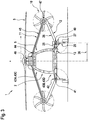
- the Y-Z plane corresponds to the front view plane of the compound helicopter 1 as illustrated in Figure 1 .
- the compound helicopter 1 is symmetrical about the yaw axis 7 and the roll axis (9 in Figure 2 ).
- the compound helicopter 1 comprises at least one propeller 10 that is at least adapted for generating forward thrust in operation.
- the at least one propeller 10 is preferentially mounted to a fixed wing arrangement 11, 12 that is laterally attached to the fuselage 2.
- the compound helicopter 1 comprises two propellers 10, one on each side of the fuselage 2.
- a predetermined distance between an underlying rotational axis of each one of the propellers 10 and the Z-axis 7 preferably corresponds at least essentially to a half wing span 37 of the compound helicopter 1.
- the upper and lower wings 11, 12 are at least interconnected at an associated interconnection region 15. At least one of the two propellers 10 is mounted to the associated interconnection region 15.
- the upper wing 11 preferably exhibits an anhedral angle 34 relative to the horizontal Y-axis 8 of the compound helicopter 1.
- the lower wing 12 is preferentially polyhedral and comprises an inboard section 25 with a span length 30 and an outboard section 26 with a span length 31.
- the span length 31 is at least two to ten times longer than the span length 30.
- the inboard section 25 is preferably connected to the fuselage 2 at the lower wing root joint area 13 and to the outboard section 26 at a sections interconnection region 27.
- the inboard section 25 is an integral part of the fuselage 2.
- the outboard section 26 is connected to the inboard section 25 at the sections interconnection region 27 and to the upper wing 11 at the associated interconnection region 15.
- the outboard section 26 is removably attached to the inboard section 25 at the sections interconnection region 27 and the upper wing 11 is removably attached to the upper wing root joint area 14.
- the inboard section 25 is at least essentially horizontal
- the outboard section 26 is at least essentially inclined upwardly, such that the sections interconnection region 27 preferably defines a dihedral kink of the lower wing 12.
- the compound helicopter 1 further comprises the at least one main rotor 3, the fixed wing arrangement 11, 12, the two propellers 10 and the main landing gear 28.
- each one of the propellers 10 comprises a housing 21 that is rigidly attached to an associated one of the interconnection regions 15 of Figure 1 .
- the propeller disc 10a of each propeller spans up a propeller disc plane 58.
- the fixed wing arrangement 11, 12 comprises the upper and lower wings 11, 12, wherein the lower wing 12 is composed of the inboard section 25 and the outboard section 26.
- the upper wing 11 is removably attached to the upper wing root joint area 14 by means of a hinged root joint 44.
- the fixed wing arrangement out of 11 and 12 shows a positive stagger, with a leading edge of the upper wing 11 being ahead of corresponding leading edges of the inboard section 25 and the outboard section 26 of the lower wing 12.
- the stagger is defined as a difference in longitudinal position of the axis of two wings of the compound helicopter 1.
- the main landing gear 28 is preferentially mainly housed within the inboard section 25 and partially within the fuselage 2.
- the outboard section 26 of the lower wing 12 is removably attached to the inboard section 25 thereof at the sections interconnection region 27 by means of a hinged joint 40 or a clamped joint 41.
- the outboard section 26 comprises wing spars 59 and the fuselage 2 is provided with wing attachment frames 43.
- the hinged joint 40 or the clamped joint 41 preferentially connects the wing spars 59 to the wing attachment frames 43.
- the clamped joint 41 is capable of transferring moments about all axes, i. e. the Z-axis 7 of Figure 1 , the Y-axis 8 and the X-axis 9, whereas the hinged joint 40 is not capable of transferring moments about the longitudinal X-axis 9.
- the first quarter chord line 51 is essentially horizontal, whereas the second quarter chord line 50 preferably exhibits a pronounced forward angle from the horizontal Y-axis 8, i. e. a negative sweep.
- a quarter chord line 19 thereof preferably essentially.-exhibits a rearward sweep angle 17 from the horizontal Y-axis 8.
- the quarter chord line 19 and the quarter chord line 57 of the outboard section 26 illustratively define a relative sweep angle 53 between the upper wing 11 and the outboard section 26.
- Figure 3 shows the compound helicopter 1 of Figure 1 with the fuselage 2, the at least one main rotor 3, the fixed wing arrangement 11, 12, the two propellers 10 and the main landing gear 28.
- Each one of the two propellers 10 is preferably powered by an associated propeller drive shaft 45, which is housed within the upper wing 11 and preferentially connects a main gar box 46 of the compound helicopter 1, illustratively arranged on the upper side 5 of the fuselage 2, with a respective propeller gear box 47.
- the fixed wing arrangement 11, 12 comprises the upper and lower wings 11, 12, wherein the lower wing 12 is composed of the inboard section 25 and the outboard section 26.
- the inboard section 25 is a structural part of the fuselage 2 and the main landing gear 28 has an associated trunnion joint 42 that is allocated within the inboard section 25.
- Corresponding attachment spars which are usually provided in the lower wing 12 and in the upper wing 11 (59 in Figure 2 ), are connected to associated wing attachment frames 43C, 43D.
- attachment spars that are provided in the lower wing 12 are connected to lower portions 43B of its associated wing attachment frame 43D allocated within the inboard section 25.
- the upper wing 11 is connected to an upper portion 43A of its associated wing attachment frame 43C, preferably by the hinged root joint 44, which is not capable of transferring moments about the longitudinal X-axis 9 of Figure 2 .
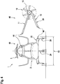
- Figure 4 shows the compound helicopter 1 of Figure 1 with the fuselage 2, the at least one main rotor 3, the fixed wing arrangement 11, 12, one of the two propellers 10 and the main landing gear 28.
- the fixed wing arrangement 11, 12 comprises the upper and lower wings 11, 12, wherein the lower wing 12 is composed of the inboard section 25 and the outboard section 26.
- the compound helicopter 1 is shown in an exemplary transportation condition, corresponding to a transport or storage configuration. More specifically, in this transportation condition the upper wing 11 and the outboard section 26 of the lower wing 12 are preferably dismounted. Consequently, the propeller 10, which is arranged at the interconnection region 15 of the upper and lower wings 11, 12, is likewise dismounted from the compound helicopter 1.
- the upper wing 11, the outboard section 26 and the propeller 10 illustratively define a wing assembly 48.
- the resulting wingless compound helicopter which is illustratively referred to with the reference number 49, is shown with folded rotor blades of the at least one main rotor 3 and stands on its main landing gear 28 and its nose landing gear 29.
- the wingless compound helicopter 49 has a total width 63 that preferably corresponds to a maximum allowable width for transportability.
- the wing assembly 48 including the upper wing 11, the outboard section 26 and the propeller 10 is separately assembled, stored and transported and preferably re-assembled as a pre-assembled unit to the wingless compound helicopter 49. This can easily be done by connecting the upper wing hinged root joint 44 and the lower hinged or clamped joint 40, respectively 41, of Figure 2 and Figure 3 .
- Figure 5 shows the compound helicopter 1 of Figure 1 with the fuselage 2, the at least one main rotor 3, the fixed wing arrangement 11, 12, one of the two propellers 10 and the main landing gear 28.
- the fixed wing arrangement 11, 12 comprises the upper and lower wings 11, 12, wherein the lower wing 12 is composed of the inboard section 25 and the outboard section 26.
- the inboard section 25 now exhibits a negative dihedral angle 32, which is preferably comprised in a range between 0° to 30°.
- the negative dihedral angle 32 defines a pronounced downward angle from the horizontal Y-axis 8. This advantageously results in a shorter required landing gear length 35, a larger upward fillet angle 39 of the inboard section 25 to the fuselage 2, a larger wing interference angle 62 between the outboard section 26 and the upper wing 11, and a more pronounced dihedral angle 32b of the outboard section 26.
- Figure 6 shows the compound helicopter 1 of Figure 1 with the fuselage 2, the at least one main rotor 3, the fixed wing arrangement 11, 12 and the two propellers 10.
- the fixed wing arrangement 11, 12 comprises the upper and lower wings 11, 12, wherein the lower wing 12 is composed of the inboard section 25 and the outboard section 26.
- the inboard section 25 now comprises a pronounced leading edge root extension 54 and a trailing edge root extension 55.
Description
- The invention is related to a compound helicopter with a fuselage, at least one main rotor that is at least adapted for generating lift in operation, and a fixed wing arrangement that is laterally attached to the fuselage, said compound helicopter comprising the features of
claim 1. - Compound helicopters and so-called convertiplanes are basically the most relevant concepts aiming to overcome horizontal flight deficiencies of conventional helicopters, i. e. helicopters with a main rotor and an auxiliary tail rotor that is adapted to counter torque, by introducing attributes of fixed-wing aircrafts to such conventional helicopters as compromise. However, a compromise between both aircraft types has always to be conveniently adapted to a planned mission profile of a given helicopter.
- An exemplary convertiplane is e. g. described in the document
US 5,046,684 A . More specifically, the latter describes a tiltrotor aircraft with a fuselage and a fixed wing arrangement. On each side of the fuselage a first and a second wing are arranged. The first wing is fixed at substantially the bottom of the fuselage and substantially unperforated in hovering as well as forward flight. The second wing is fixed at substantially the top of the fuselage, or fixed to a structure extending above the fuselage, and is likewise substantially unperforated in hovering as well as forward flight. At least one of the first and second wings has dihedral so that the wings converge to join or nearly join at their tips. Furthermore, unducted rotor means are provided for generating aerodynamic lift sufficient for highly efficient hovering flight and for propelling the tiltrotor aircraft at speeds approaching roughly four hundred knots in forward cruising flight. The unducted rotor means are supported on the first and second wings, at or near the tips of the first and second wings. They can be pivoted for operation, in different orientations in hovering and forward flight respectively. - In other words, according to the document
US 5,046,684 A , the tiltrotor aircraft features two fully tiltable rotors, one at each side of the fuselage, and which are respectively arranged at the tips of a joined wing of the fixed wing arrangement. In this fixed wing arrangement, the lower, i. e. first wing is straight and positively swept, and the upper, i. e. second wing is straight and exhibits a very pronounced negative sweep. The upper wing is anhedral and connects the tip of the lower wing of the fixed wing arrangement to the tip of the tiltrotor aircraft's fin. - In contrast to such a tiltrotor aircraft, winged compound helicopter configurations with separate propulsion units typically feature a monoplane design with one set of wing surfaces in cantilever design as shoulder-wing arrangement. A compound helicopter with lift compounding, thrust compounding or a combination of both basically aims to off-load a respective main rotor from its simultaneous lifting and propulsive duties to allow for higher forward speeds of the compound helicopter.
- More specifically, lift compounding entails adding wings to a helicopter, hence enabling to increase an underlying load factor of the helicopter and to reach a higher maneuverability. This improves the efficiency of the helicopter at moderately high speed but at the expense of reduced efficiencies at lower forward speeds and in the hover.
- Thrust compounding implies the addition of essentially horizontally oriented auxiliary propulsion units to the helicopter. This has been typically accomplished by means of a single or a pair of propellers being driven by drive shafts powered by main turboshaft engines of the helicopter. The use of a pair of propulsion units has the advantage of providing for anti-torque capabilities without the need of an additional tail rotor, hence relativizing the inherent system complexity of the thrust compound configuration.
- A more extended configuration of a compound helicopter includes both the addition of wings and propulsion units. In this case, lift during cruise is simultaneously provided by a given main rotor - in powered condition - usually addressed as "hybrid helicopter" - or in autorotation - "autogyro" - modus - and the wings. Higher forward speed is provided by horizontally oriented auxiliary propulsion units of the compound helicopter. The compound helicopter hence overcomes underlying rotor lift limits by means of the wings and underlying rotor thrust limits by means of the propulsion units. As a result, a higher load factor is obtained along with potential for higher speed. In particular, use of a pair of thrust propulsion units - opposed and both offset relative to each other and to a longitudinal axis of the compound helicopter - enables for a simultaneous torque correction.
- Exemplary compound helicopters with two wing-mounted propellers defining the above-described propulsion units are described in the
documents EP 2 146 896 A1 ,EP 2 690 011 A1US 2013/0175385 A1 . These exemplary compound helicopters are all provided with fixed wing arrangements, as described hereinafter. - The
document EP 2 146 896 A1 describes a compound helicopter with a fixed wing arrangement in the form of a cantilevered wing configuration that comprises pusher propellers that are installed at tips of straight and plane cantilevered wings with associated drive shafts that are respectively housed within the wings. Corresponding housings of the propeller drive shafts that are arranged inside the wings require an underlying wing planform to be straight. Furthermore, the cantilevered wing configuration requires a large wing root thickness and a continuation of wing bending capabilities throughout an upper fuselage deck. In general, such a cantilevered wing configuration comprises straight wings, wherein each of the wings has a constant sweep and constant anhedral. - The document
EP2690011 describes a compound helicopter with a fixed wing arrangement in the form of a joined-wing configuration, wherein a lower wing and an upper wing are provided on each side of the compound helicopter. Both wings are essentially straight and interconnected to each other at a wing interconnection region, and a pusher propeller is installed in the interconnection region behind associated trailing edges of both wings. This joined-wing configuration especially outstands by its improved mechanical efficiency in terms of less structural weight and larger stiffness, as well as by improved inherent operational safety characteristics and improved system integration, especially referring to an underlying accessibility of a main gear box of the compound helicopter. - The document
EP2418148 describes an airliner aircraft having a lambda-box wing configuration. The aircraft comprises a fuselage, a propulsion system with turbojets, a first pair of swept-back airfoils, connected to the top forward portion of the fuselage. A second pair of swept-forward airfoils is connected to the lower rear portion of the fuselage at a point of the fuselage aft of the connection of the swept-back airfoils. A third pair of substantially vertical airfoils is provided between the tips of the swept-forward airfoils and the lower side of the swept-back airfoils. - The propulsion system has one engine mounted in the extension middle of each of the first swept-back airfoils, either directly or on top of a further stand. The swept-back airfoils extend with an outwardly upwards angle with respect to the horizontal plane. The second pair of swept-forward airfoils are frankly shaped.
- The document
US4856736 describes an aircraft having paired aerofoils where wing tips are joined in the same plane one behind the other. The trailing edge of the forward wings and the leading edge of the rearward wings is coincidental in plan view at the wing tip. A single propeller is mounted at a front end of the fuselage in an embodiment. A pair of propellers is mounted at a front end of the fuselage, each on a canard pole, in another embodiment. - The document
US6098923 describes a jet aircraft structure that provide inherent directional stability, even at very high angles-of-attack where conventional means of stabilization are ineffective. Components attached to an aircraft fuselage include a wing, horizontal stabilizers and vertical stabilizers. On the fuselage, are provided a front inlet and a rear exhaust nozzle. - The document
US2290850 describes a folding wing airplane, where end sections of each wings can be folded upwards. The fuselage includes a front central propeller. - The document
US8657226 describes synergistic control enhancement and drag reduction benefits in an aircraft having independent airfoils producing downward force opposite to wing lift in normal flight. The airfoils are supported in specific wingtip locations. The aircraft is of fixed wing type, with propellers mounted on the fuselage, on poles in some embodiments. - The document
US20130175383 describes another compound helicopter with fixed wing arrangement in the form of a joined-wing configuration having lower and upper wings that are each parallel to a given pitch axis of the compound helicopter. The wings exhibit a constant dihedral and the upper wings entirely cover the lower wings so as to minimize down-wash drag. This translates to a design with same depth of the wings, same wing orientation, and same position of attachment of the upper and lower wings. - However, all of the above-described compound helicopters have drawbacks when used as high-speed helicopters, as their fixed wing arrangements are not optimized with respect to high-speed regime in operation of the compound helicopters. Furthermore, the respective wings of the fixed wing arrangements are not adequate for main landing gear integration and they can be improved with respect to wing interconnection and wing-to-fuselage transition. Moreover, the operational efficiency of these compound helicopters as a whole can be improved.
- It is, therefore, an object of the present invention to provide a new compound helicopter that overcomes the above described drawbacks.
- This object is solved by a compound helicopter with a fuselage, at least one main rotor that is at least adapted for generating lift in operation, and a fixed wing arrangement that is laterally attached to the fuselage, said compound helicopter comprising the features of
claim 1. - More specifically, according to the present invention a compound helicopter with a fuselage and at least one main rotor that is at least adapted for generating lift in operation is provided. The fuselage comprises a lower side and an upper side that is opposed to the lower side. The at least one main rotor is arranged at the upper side. At least one propeller is provided that is at least adapted for generating forward thrust in operation, the at least one propeller being mounted to a fixed wing arrangement that is laterally attached to the fuselage. The fixed wing arrangement comprises at least one upper wing that is arranged at an upper wing root joint area provided at the upper side of the fuselage and at least one lower wing that is arranged at a lower wing root joint area provided at the lower side of the fuselage. The upper and lower wings are at least interconnected at an associated interconnection region. Each of the at least one propeller is mounted to an associated interconnection region and the compound helicopter is provided with a wheel-type main landing gear.
- The lower wing comprises an inboard section defining a first quarter chord line and a first centroidal axis and an outboard section defining a second quarter chord line and a second centroidal axis. The inboard section is an integral part of the fuselage at the lower wing root joint area and connected to the outboard section at a sections interconnection region. The wheel-type main landing gear is mounted to said inboard section adjacent to said sections interconnection region. The outboard section is connected to the inboard section at the sections interconnection region and to the upper wing at the associated interconnection region. The second centroidal axis is inclined relative to the first centroidal axis by a relative dihedral angle that is defined in a first coordinate plane. The second quarter chord line is inclined relative to the first quarter chord line by a relative sweep angle that is defined in a second coordinate plane.
- In general, the compound helicopter according to the present invention comprises a specific arrangement and planform of an underlying bi-plane wing structure on each side of the compound helicopter, with a main rotor providing lift and a pair of additional propulsion devices, i.e. propellers, providing thrust. The bi-plane wing structure on each side of the compound helicopter provides additional lift during horizontal cruise flight. The additional propulsion devices are arranged on the underlying bi-plane wing structure at the intersections of respective wings, preferentially one at each side of the compound helicopter.
- More specifically, the inventive compound helicopter preferably comprises a new joined-wing configuration with a new wing planform. In contrast to a conventional wing planform with boxed or joined wings, wherein the wings are essentially straight along their spanwise extension and respectively exhibit an essentially constant sweep and constant dihedral, the new wing planform according to the present invention uses a unique shape and layout of a given lower wing featuring a simultaneous "polyhedral" and "multi-sweep" design. The term "polyhedral" addresses use of two different wing portions with two different dihedral angles, whereas the term "multi-sweep" addresses use of two different wing portions with two different sweep angles.
- The dihedral angle is defined as an angle of the centroidal axis of the wing with respect to the horizontal Y-axis, i. e. pitch axis, of the compound helicopter and basically represents an inclination of the wing in a front view plane of the compound helicopter with respect to a horizontal plane. The sweep angle is defined as an angle between the quarter chord line of the wing and a transverse Y-axis of the helicopter, the quarter chord line being the line which spans 25% of the wing chord. The lower wing is, hence, characterized by a cranked layout with one inboard section and one outboard section, both featuring different dihedral and sweep angles.
- Advantageously, reduction of the dihedral angle of the lower wing at its root region improves an underlying aerodynamic efficiency of a given wing-fuselage transition. Furthermore, reduction of the sweep angle at the inboard wing section allows keeping its rear main spar away from a predefined propeller burst cone and allows for a clean transition layout from the lower wing's trailing edge to the intermediate compound helicopter structure.
- The inboard section of the lower wing preferably exhibits a lower dihedral angle and lower sweep angle in comparison to the outboard section. An almost un-swept inboard section with a low sweep angle, essentially perpendicular to the longitudinal axis of the compound helicopter, is advantageous with respect to main landing gear integration and to a resulting aerodynamic center of lift. Main landing gear integration with standard kinematics preferably requires perpendicular support elements at each side of the main landing gear, which are conveniently provided by the two spars of the inboard section. An underlying aerodynamic center of lift should not exceed a specific longitudinal distance from an underlying center of gravity in order to maintain adequate aerodynamic balance at high-speed operation of the compound helicopter.
- According to one aspect of the present invention, a main landing gear is attached to the lower wing at its kink region, i. e. a transition region of the inboard section of the lower wing to the outboard section of the lower wing, and at least partially housed, in its retracted position, within the inboard section. The kink region separates the inboard section from the outboard section and is preferably, a structural releasable joint that allows an easy separation of both lower wing sections from each other.
- Advantageously, separation of the lower wing into an inboard section and an outboard section allows for a structural integration of the inboard section and the main landing gear to the fuselage. Hence, a disassembly of the lower wing and/or the lower and upper wings does not involve a removal of the main landing gear from the fuselage. Furthermore, in a storage or transportation condition the inventive compound helicopter is able to stay on its own supports.
- The inboard section is preferably a structural part of the fuselage which integrates the main landing gear attachment points. The attachment of the inboard section to the outboard section can either be hinged or clamped. A purely hinged joint has fewer interconnections and lesser associated assembly tolerance issues.
- Advantageously, in the case of a hinged joint between the inboard section and the outboard section, a dihedral kink introduces in a load scenario with large down loads a transverse load and bending load component which counteracts - at least to a certain extent - respective reaction loads of the main landing gear. Thus, an underlying stress state of respective main load carrying r members of the inboard section and its structural interconnection to the fuselage can be alleviated. The dihedral kink provides for a roughly 10% larger airfoil thickness of the inboard section of the lower wing in comparison to the outboard section, hence providing for additional available volume for the main landing gear introduction without a need for increasing or tapering the thickness of the outboard section.
- Advantageously, an underlying wheel base, i. e. a distance between left-hand and right-hand wheels of the main landing gear, is increased by the new two-plane joined wing configuration without increasing an underlying length and consequently a respective weight of the main landing gear. More specifically, especially high speed compound helicopters require fuselages with reduced widths and reduced front masking areas. This is crucial aiming at a reduction of an underlying aerodynamic drag for increasing the performance and efficiency of the compound helicopters. Narrow fuselage bodies, however, require a particularly large wheel base in order to ensure ground stability and avoid overturn.
- In the case of a compound helicopter with two propellers with considerable diameter at each side of its fuselage, there is a crucial need for ground clearance in order to avoid a clash of the propellers to the ground. This safety requirement leads to a minimum ground clearance angle off the horizontal from an underlying main wheel position to a given propeller disc, which is a function of a position of the propeller, its diameter and the wheel base. The position of the propeller and its diameter are a function of the compound helicopter performance requirements and are simultaneously constrained by a required clearance between respective rotor blades of the at least one main rotor and the propeller. Hence, basic parameters to influence the ground clearance are the wheel base and a predetermined height of the main landing gear.
- Based on these clearance requirements, narrow fuselage bodies tend to require long and heavy main landing gears. While conventional joined-wing configurations with joined wings and a pronounced and constant dihedral on the lower wing as described above alleviate this tendency, since they allow integration of the main landing gear to the lower wing of the joined-wing configuration instead of the fuselage, the new joined-wing configuration allows maintaining a constant length and, consequently, a constant weight of the main landing gear independently of its wheel base. Thus, the new joined-wing configuration provides for a favourable flexibility in terms of the main landing gear arrangement in view of the clearance requirements.
- It should, however, be noted that an additional wing structural weight resulting from the above described kink design of the lower wing and a respective diminution of specific stiffness is negligible in comparison to an obtained main landing gear weight reduction resulting from its length reduction. In comparison to a conventional joined-wing configuration with a conventional straight, monohedral lower wing, the new joined-wing configuration enables provision of a 10% lighter main landing gear.
- Furthermore, the new joined-wing configuration and the new wing planform allow for an easy integration of conventional main landing gears with simple designs and retraction kinematics, hence providing for less development risks, lesser weight and larger robustness. The main landing gears can be designed to rotate during retraction around an essentially longitudinal axis and be housed - at least partially - within the inboard section of the lower wing at the largest width between two main spars, the spars being essentially perpendicular to the longitudinal compound helicopter axis.
- According to one aspect of the present invention, a leading and trailing edge root extension can be integrated within the inboard section of the lower wing. The strake allows for an increase of lift for combat manoeuvring and switches the aerodynamic center of lift further fore. Furthermore, it offers additional volume for equipment housing.
- According to one aspect of the present invention, the new two-plane joined-wing configuration is realizable either with a positive stagger or a negative stagger. A positive stagger results by a leading edge of the upper wing being ahead, i. e. upstream, of a leading edge of the lower wing. A negative stagger results by the leading edge of the upper wing being behind, i. e. downstream, of the leading edge of the lower wing.
- A positive stagger is rather suitable for a tricycle landing gear arrangement, with two main wheels aft of the compound helicopter's center of gravity and an auxiliary wheel ahead of the center of gravity. In contrast, a negative stagger is rather suitable for a tail dragger landing gear arrangement, with two main wheels forward of the compound helicopter's center of gravity and an auxiliary wheel at its tail.
- According to a preferred embodiment, the relative dihedral angle is comprised in a range between 5° and 45° and the first coordinate plane is defined by a front view plane of the compound helicopter.
- According to a further preferred embodiment, the relative sweep angle is comprised in a range between 5° and 45° and the coordinate plane is defined by a top view plane of the compound helicopter.
- According to a further preferred embodiment, the upper wing is removably attached to the upper wing root joint area and the outboard section is removably attached to the inboard section at the sections interconnection region.
- According to a further preferred embodiment, the upper wing is removably attached to the upper wing root joint area by means of a hinged root joint and the outboard section is removably attached to the inboard section at the sections interconnection region by means of a hinged joint or a clamped joint.
- According to a further preferred embodiment, the outboard section comprises wing spars and the fuselage is provided with wing attachment frames. The hinged joint or the clamped joint connects the wing spars to the wing attachment frames.
- According to a further preferred embodiment, the wheel-type main landing gear is at least partly retractable into the inboard section in operation.
- According to a further preferred embodiment, the first quarter chord line is at least essentially parallel to the first coordinate plane with a maximum variance comprised in a range of ±5°.
- According to a further preferred embodiment, the inboard section exhibits a negative dihedral angle comprised in a range between 0° to 30°.
- According to a further preferred embodiment, the outboard section comprises a span length that is at least two to ten times longer than a span length of the inboard section.
- According to a further preferred embodiment, the lower wing root joint area and the upper wing root joint area define a transversal wing attachment basis in height direction of the fuselage and a longitudinal wing attachment basis in longitudinal direction of the fuselage. The transversal wing attachment basis is at least one to five times larger than the longitudinal wing attachment basis.
- According to a further preferred embodiment, the at least one propeller is mounted to the associated interconnection region.
- According to a further preferred embodiment, the fixed wing arrangement comprises at least one pair of upper and lower wings arranged on a board side of the compound helicopter and at least one pair of upper and lower wings arranged on a starboard side of the compound helicopter. The at least one pair of upper and lower wings arranged on the starboard side of the compound helicopter comprise the at least one upper wing and the at least one lower wing.
- Preferred embodiments of the invention are outlined by way of example in the following description with reference to the attached drawings. In these attached drawings, identical or identically functioning components and elements are labeled with identical reference numbers and characters and are, consequently, only described once in the following description.
-
Figure 1 shows a front view of a compound helicopter according to a first embodiment of the present invention, -
Figure 2 shows a top view of the compound helicopter ofFigure 1 , -
Figure 3 shows a sectional view of the compound helicopter ofFigure 1 , -
Figure 4 shows a front view of the compound helicopter ofFigure 1 in transportation condition, -
Figure 5 shows a front view of a compound helicopter according to a second embodiment of the present invention, and -
Figure 6 shows a top view of the compound helicopter ofFigure 5 . -
Figure 1 shows acompound helicopter 1 according to the present invention. Thecompound helicopter 1 illustratively comprises afuselage 2 with anoverall height 38, which exhibits alower side 4 and anupper side 5 that is opposed to thelower side 4. Furthermore, thecompound helicopter 1 comprises at least onemain rotor 3 that is at least adapted for generating lift in operation. The at least onemain rotor 3 is arranged at theupper side 5 of thefuselage 2 and, by way of example, anempennage 6 is rigidly mounted to a tail boom (16 inFigure 2 ) defined by thefuselage 2. - For purposes of illustration, the
compound helicopter 1 is shown with three mutually orthogonal directions X, Y and Z forming a three-dimensional frame of reference XYZ. A "longitudinal" direction X corresponds to the roll axis (9 inFigure 2 ) inherent to thecompound helicopter 1. Another direction Y, said to be "transverse", is perpendicular to the roll axis (9 inFigure 2 ) and corresponds to thepitch axis 8 of thecompound helicopter 1. The X-Y plane is considered to be "horizontal" and corresponds to a top view plane of thecompound helicopter 1, cp.Figure 2 . A third direction Z corresponds to theyaw axis 7 of thecompound helicopter 1, oriented perpendicular with respect to the X-Y plane. The Y-Z plane corresponds to the front view plane of thecompound helicopter 1 as illustrated inFigure 1 . According to one aspect of the present invention, thecompound helicopter 1 is symmetrical about theyaw axis 7 and the roll axis (9 inFigure 2 ). - Preferably, the
compound helicopter 1 comprises at least onepropeller 10 that is at least adapted for generating forward thrust in operation. The at least onepropeller 10 is preferentially mounted to a fixedwing arrangement fuselage 2. Illustratively, thecompound helicopter 1 comprises twopropellers 10, one on each side of thefuselage 2. A predetermined distance between an underlying rotational axis of each one of thepropellers 10 and the Z-axis 7 preferably corresponds at least essentially to ahalf wing span 37 of thecompound helicopter 1. - According to one aspect of the present invention, the fixed
wing arrangement upper wing 11 that is arranged at an upper wing rootjoint area 14 provided at theupper side 5 of thefuselage 2, and at least onelower wing 12 that is arranged at a lower wing rootjoint area 13 provided at thelower side 4 of thefuselage 2. In the illustrated Y-Z plane, a predetermined distance in z-direction between both the lower wing rootjoint area 13 and the upper wing rootjoint area 14 defines a transversalwing attachment basis 60. - By way of example, the fixed
wing arrangement lower wings compound helicopter 1 and at least one pair of upper andlower wings compound helicopter 1. At least one pair of upper andlower wings compound helicopter 1 comprises the at least oneupper wing 11 and the at least onelower wing 12, which are described in greater detail hereinafter. - Preferably, the upper and
lower wings interconnection region 15. At least one of the twopropellers 10 is mounted to the associatedinterconnection region 15. - The
upper wing 11 preferably exhibits ananhedral angle 34 relative to the horizontal Y-axis 8 of thecompound helicopter 1. Thelower wing 12 is preferentially polyhedral and comprises aninboard section 25 with aspan length 30 and anoutboard section 26 with aspan length 31. Preferably, thespan length 31 is at least two to ten times longer than thespan length 30. - The
inboard section 25 is preferably connected to thefuselage 2 at the lower wing rootjoint area 13 and to theoutboard section 26 at asections interconnection region 27. Preferentially, theinboard section 25 is an integral part of thefuselage 2. Theoutboard section 26 is connected to theinboard section 25 at thesections interconnection region 27 and to theupper wing 11 at the associatedinterconnection region 15. - According to one aspect of the present invention, the
outboard section 26 is removably attached to theinboard section 25 at thesections interconnection region 27 and theupper wing 11 is removably attached to the upper wing rootjoint area 14. Illustratively, theinboard section 25 is at least essentially horizontal, whereas theoutboard section 26 is at least essentially inclined upwardly, such that thesections interconnection region 27 preferably defines a dihedral kink of thelower wing 12. - The
inboard section 25 illustratively defines a first quarter chord line (51 inFigure 2 ) and a firstcentroidal axis 56. Theoutboard section 26 illustratively defines a second quarter chord line (50 inFigure 2 ) and a secondcentroidal axis 57. - The
inboard section 25 and theoutboard section 26 exemplarily exhibit differentdihedral angles dihedral angle centroidal axis outboard section axis 8 of thecompound helicopter 1. In other words, thedihedral angle 32a is defined as the angle of thecentroidal axis 56 with respect to the horizontal Y-axis 8 and thedihedral angle 32b is defined as the angle of thecentroidal axis 57 with respect to the horizontal Y-axis 8. Thedihedral angle 32a is essentially horizontal, whereas thedihedral angle 32b represents a pronounced upward angle from the horizontal Y-axis 8, i. e. a positive dihedral. - According to one aspect of the present invention, the second
centroidal axis 57 is inclined relative to the firstcentroidal axis 56 by a relativedihedral angle 33. The latter is defined in a coordinate plane that is defined by a front view plane of thecompound helicopter 1, i. e. the illustrated Y-Z plane, as a difference angle between thedihedral angles dihedral angle 33 is comprised in a range between 5° and 45°. - According to one aspect of the present invention, the
compound helicopter 1 comprises a wheel-typemain landing gear 28. The latter is preferably mounted to theinboard section 25 of thelower wing 12, preferentially adjacent to thesections interconnection region 27. Furthermore, the wheel-typemain landing gear 28 is preferentially at least partly retractable into theinboard section 25 in operation of thecompound helicopter 1. An underlying distance between the Z-axis 7 and a predetermined landing gear standing position, e. g. as illustrated onground 22, is defined as a so-calledhalf wheel base 36. - Illustratively, the
compound helicopter 1 further comprises a wheel-typenose landing gear 29. The latter is preferably arranged at a nose section of thefuselage 2, i. e. upstream of themain landing gear 28. - It should be noted that it is required for a safe operation of the
compound helicopter 1 to maintain on the one hand a specified clearance between a given contact point of themain landing gear 28 with theground 22 and a givendisc 10a of thepropeller 10, defined by an underlyingground clearance angle 24, and on the other hand a specified clearance between the at least onemain rotor 3 and thepropeller disc 10a, defined by aclearance angle 23. Consequently, the mutual configuration of an underlying landing gear length/clearance to ground 35, thehalf wheel base 36, thehalf wing span 37, thepropeller disc 10a and theoverall fuselage height 38 are a function of the clearance angles 23, 24. For instance, a largerhalf wheel base 36 leads to alarger span length 30 of theinboard section 25 and allows provision of a smalleroverall fuselage height 38 and a reduced landing gear length for a givenground clearance angle 24, and so on. -
Figure 2 shows thecompound helicopter 1 ofFigure 1 with thefuselage 2 having atail boom 16, to which theempennage 6 is rigidly mounted.Figure 2 further illustrates the roll axis that is inherent to thecompound helicopter 1, i. e.X-axis 9. - As described above with reference to
Figure 1 , thecompound helicopter 1 further comprises the at least onemain rotor 3, the fixedwing arrangement propellers 10 and themain landing gear 28. Preferably, each one of thepropellers 10 comprises ahousing 21 that is rigidly attached to an associated one of theinterconnection regions 15 ofFigure 1 . Illustratively, thepropeller disc 10a of each propeller spans up apropeller disc plane 58. The fixedwing arrangement lower wings lower wing 12 is composed of theinboard section 25 and theoutboard section 26. Preferably, theupper wing 11 is removably attached to the upper wing rootjoint area 14 by means of a hinged root joint 44. - Illustratively, the fixed wing arrangement out of 11 and 12 shows a positive stagger, with a leading edge of the
upper wing 11 being ahead of corresponding leading edges of theinboard section 25 and theoutboard section 26 of thelower wing 12. The stagger is defined as a difference in longitudinal position of the axis of two wings of thecompound helicopter 1. Themain landing gear 28 is preferentially mainly housed within theinboard section 25 and partially within thefuselage 2. - According to one aspect of the present invention, the
outboard section 26 of thelower wing 12 is removably attached to theinboard section 25 thereof at thesections interconnection region 27 by means of a hinged joint 40 or a clamped joint 41. Preferably, theoutboard section 26 comprises wing spars 59 and thefuselage 2 is provided with wing attachment frames 43. The hinged joint 40 or the clamped joint 41 preferentially connects the wing spars 59 to the wing attachment frames 43. The clamped joint 41 is capable of transferring moments about all axes, i. e. the Z-axis 7 ofFigure 1 , the Y-axis 8 and theX-axis 9, whereas the hinged joint 40 is not capable of transferring moments about thelongitudinal X-axis 9. - Illustratively, the
inboard section 25 defines a firstquarter chord line 51 and theoutboard section 26 defines a secondquarter chord line 50. The firstquarter chord line 51 is preferentially at least essentially parallel to the coordinate plane that is defined by the front view plane of thecompound helicopter 1, i. e. the Y-Z plane illustrated inFigure 1 . - As described above with reference to
Figure 1 , theupper wing 11 is arranged at the upper wing rootjoint area 14 and thelower wing 12 is arranged at the lower wing rootjoint area 13, both of which define the transversalwing attachment basis 60 in height direction of thefuselage 2, i. e. in direction of the Z-axis 7. Illustratively, the lower wing rootjoint area 13 and the upper wing rootjoint area 14 further define a longitudinalwing attachment basis 61 in longitudinal direction of thefuselage 2, i. e. along the roll axis of thecompound helicopter 1 that defines theX-axis 9. The transversalwing attachment basis 60 is preferably at least one to five times larger than the longitudinalwing attachment basis 61. - According to one aspect of the present invention, the
lower wing 12 is multi-swept with theinboard section 25 and theoutboard section 26, which exhibit different sweep angles. Each sweep angle is defined as an angle of a respective one of thequarter chord lines axis 8 of thecompound helicopter 1. Furthermore, arelative sweep angle 52 is a difference angle between the sweep angles of theinboard section 25 and theoutboard section 26. Preferably, therelative sweep angle 52 is defined by an inclination of the secondquarter chord line 50 relative to the firstquarter chord line 51, which is defined in a coordinate plane that is defined by a top view plane of thecompound helicopter 1, i. e. the X-Y plane illustrated inFigure 2 . Therelative sweep angle 52 is preferably comprised in a range between 5° and 45°. - Illustratively, with respect to the
lower wing 12, the firstquarter chord line 51 is essentially horizontal, whereas the secondquarter chord line 50 preferably exhibits a pronounced forward angle from the horizontal Y-axis 8, i. e. a negative sweep. With respect to theupper wing 11, aquarter chord line 19 thereof preferably essentially.-exhibits arearward sweep angle 17 from the horizontal Y-axis 8. Thequarter chord line 19 and thequarter chord line 57 of theoutboard section 26 illustratively define arelative sweep angle 53 between theupper wing 11 and theoutboard section 26. -
Figure 3 shows thecompound helicopter 1 ofFigure 1 with thefuselage 2, the at least onemain rotor 3, the fixedwing arrangement propellers 10 and themain landing gear 28. Each one of the twopropellers 10 is preferably powered by an associatedpropeller drive shaft 45, which is housed within theupper wing 11 and preferentially connects amain gar box 46 of thecompound helicopter 1, illustratively arranged on theupper side 5 of thefuselage 2, with a respectivepropeller gear box 47. The fixedwing arrangement lower wings lower wing 12 is composed of theinboard section 25 and theoutboard section 26. - Illustratively, the
inboard section 25 is a structural part of thefuselage 2 and themain landing gear 28 has an associated trunnion joint 42 that is allocated within theinboard section 25. Corresponding attachment spars, which are usually provided in thelower wing 12 and in the upper wing 11 (59 inFigure 2 ), are connected to associated wing attachment frames 43C, 43D. Illustratively, attachment spars that are provided in thelower wing 12 are connected to lowerportions 43B of its associatedwing attachment frame 43D allocated within theinboard section 25. Theupper wing 11 is connected to anupper portion 43A of its associatedwing attachment frame 43C, preferably by the hinged root joint 44, which is not capable of transferring moments about thelongitudinal X-axis 9 ofFigure 2 . -
Figure 4 shows thecompound helicopter 1 ofFigure 1 with thefuselage 2, the at least onemain rotor 3, the fixedwing arrangement propellers 10 and themain landing gear 28. The fixedwing arrangement lower wings lower wing 12 is composed of theinboard section 25 and theoutboard section 26. - Illustratively, the
compound helicopter 1 is shown in an exemplary transportation condition, corresponding to a transport or storage configuration. More specifically, in this transportation condition theupper wing 11 and theoutboard section 26 of thelower wing 12 are preferably dismounted. Consequently, thepropeller 10, which is arranged at theinterconnection region 15 of the upper andlower wings compound helicopter 1. Theupper wing 11, theoutboard section 26 and thepropeller 10 illustratively define awing assembly 48. - The resulting wingless compound helicopter, which is illustratively referred to with the
reference number 49, is shown with folded rotor blades of the at least onemain rotor 3 and stands on itsmain landing gear 28 and itsnose landing gear 29. Preferably, thewingless compound helicopter 49 has atotal width 63 that preferably corresponds to a maximum allowable width for transportability. - According to one aspect of the present invention, the
wing assembly 48 including theupper wing 11, theoutboard section 26 and thepropeller 10 is separately assembled, stored and transported and preferably re-assembled as a pre-assembled unit to thewingless compound helicopter 49. This can easily be done by connecting the upper wing hinged root joint 44 and the lower hinged or clamped joint 40, respectively 41, ofFigure 2 andFigure 3 . -
Figure 5 shows thecompound helicopter 1 ofFigure 1 with thefuselage 2, the at least onemain rotor 3, the fixedwing arrangement propellers 10 and themain landing gear 28. The fixedwing arrangement lower wings lower wing 12 is composed of theinboard section 25 and theoutboard section 26. However, in contrast toFigure 1 theinboard section 25 now exhibits a negative dihedral angle 32, which is preferably comprised in a range between 0° to 30°. - More specifically, the negative dihedral angle 32 defines a pronounced downward angle from the horizontal Y-
axis 8. This advantageously results in a shorter requiredlanding gear length 35, a largerupward fillet angle 39 of theinboard section 25 to thefuselage 2, a largerwing interference angle 62 between theoutboard section 26 and theupper wing 11, and a more pronounceddihedral angle 32b of theoutboard section 26. -
Figure 6 shows thecompound helicopter 1 ofFigure 1 with thefuselage 2, the at least onemain rotor 3, the fixedwing arrangement propellers 10. The fixedwing arrangement lower wings lower wing 12 is composed of theinboard section 25 and theoutboard section 26. However, in contrast toFigure 1 theinboard section 25 now comprises a pronounced leadingedge root extension 54 and a trailingedge root extension 55. - Finally, it should be noted that further modifications are also within the common knowledge of the person skilled in the art and, thus, also considered as being part of the present invention. The invention is limited by the scope of the appended claims.
-
- 1
- Compound helicopter
- 2
- Fuselage
- 3
- Main Rotor
- 4
- Lower side of fuselage
- 5
- Upper side of fuselage
- 6
- Empennage
- 7
- Yaw axis
- 8
- Pitch axis
- 9
- Roll axis
- 10
- Propeller
- 10a
- Propeller disc
- 11
- Upper wing
- 12
- Lower wing
- 13
- Lower wing root joint area
- 14
- Upper wing root joint area
- 15
- Wing interconnection region of upper and lower wings
- 16
- Tail boom
- 17
- Upper wing sweep angle
- 18
- Lower wing sweep angle
- 19
- Upper wing quarter chord line
- 20
- Lower wing quarter chord line
- 21
- Propeller housing
- 22
- Ground
- 23
- Rotor clearance angle to propeller
- 24
- Ground clearance angle to propeller
- 25
- Lower wing inboard section
- 26
- Lower wing outboard section
- 27
- Sections interconnection region
- 28
- Wheel-type main landing gear
- 29
- Wheel-type nose landing gear
- 30
- Span length of lower wing inboard section
- 31
- Span length of lower wing outboard section
- 32a
- Dihedral angle of lower wing inboard section relative to horizontal (ground) plane
- 32b
- Dihedral angle of lower wing outboard section relative to horizontal (ground) plane
- 33
- Relative dihedral angle of lower wing outboard section relative to lower wing inboard section
- 34
- Anhedral angle of upper wing relative to horizontal direction
- 35
- Length of main landing gear / clearance to ground
- 36
- Half wheel base
- 37
- Half wing span
- 38
- Fuselage height
- 39
- Upward fillet angle of lower wing inboard section relative to fuselage
- 40
- Lower wing outboard section hinged joint
- 41
- Lower wing outboard section clamped joint
- 42
- Main landing gear trunnion joint
- 43, 43C, 43D
- Wing attachment frame
- 43A
- Upper portion of wing attachment frame
- 43B
- Lower portion of wing attachment frame
- 44
- Upper wing hinged root joint
- 45
- Propeller drive shaft
- 46
- Main gear box
- 47
- Propeller gear box
- 48
- Wing assembly
- 49
- Wingless helicopter
- 50
- Quarter chord line of lower wing outboard section
- 51
- Quarter chord line of lower wing inboard section
- 52
- Relative sweep angle between lower wing inboard/outboard sections
- 53
- Relative sweep angle between upper wing and lower wing outboard section
- 54
- Leading edge root extension
- 55
- Trailing edge root extension
- 56
- Centroidal axis of lower wing inboard section
- 57
- Centroidal axis of lower wing outboard section
- 58
- Propeller disc plane
- 59
- Wing spar
- 60
- Transversal wing attachment basis
- 61
- Longitudinal wing attachment basis
- 62
- Wing interference angle
- 63
- Total wingless helicopter width
Claims (13)
- A compound helicopter (1) with a fuselage (2) and at least one main rotor (3) that is at least adapted for generating lift in operation, said fuselage (2) comprising a lower side (4) and an upper side (5) that is opposed to said lower side (4), said at least one main rotor (3) being arranged at said upper side (5), wherein the compound helicopter (1) comprises at least one propeller (10) at least adapted for generating forward thrust in operation, said at least one propeller (10) being mounted to a fixed wing arrangement (11, 12) that is laterally attached to said fuselage (2), said fixed wing arrangement (11, 12) comprising at least one upper wing (11) that is arranged at an upper wing root joint area (14) provided at said upper side (5) of said fuselage (2) and at least one lower wing (12) that is arranged at a lower wing root joint area (13) provided at said lower side (4) of said fuselage (2), said upper and lower wings (11, 12) being at least interconnected at an associated interconnection region (15), each of the at least one propeller (10) being mounted to an associated interconnection region (15); the compound helicopter (1) being provided with a wheel-type main landing gear (28),
characterized in that said lower wing (12) comprises an inboard section (25) defining a first quarter chord line (51) and a first centroidal axis (56) and an outboard section (26) defining a second quarter chord line (50) and a second centroidal axis (57), said inboard section (25) being an integral part of said fuselage (2) at said lower wing root joint area (13) and connected to said outboard section (26) at a sections interconnection region (27), said wheel-type main landing gear (28) being mounted to said inboard section (25) adjacent to said sections interconnection region (27) and said outboard section (26) being connected to said inboard section (25) at said sections interconnection region (27) and to said upper wing (11) at said associated interconnection region (15), wherein said second centroidal axis (57) is inclined relative to said first centroidal axis (56) by a relative dihedral angle (33) that is defined in a first coordinate plane, and wherein said second quarter chord line (50) is inclined relative to said first quarter chord line (51) by a relative sweep angle (52) that is defined in a second coordinate plane. - The compound helicopter (1) according to claim 1,
characterized in that said relative dihedral angle (33) is comprised in a range between 5° and 45°, said first coordinate plane being defined by a front view plane of said compound helicopter (1). - The compound helicopter (1) according to claim 2,
characterized in that said relative sweep angle (52) is comprised in a range between 5° and 45°, said second coordinate plane being defined by a top view plane of said compound helicopter (1). - The compound helicopter (1) according to claim 1,
characterized in that said upper wing (11) is removably attached to said upper wing root joint area (14) and that said outboard section (26) is removably attached to said inboard section (25) at said sections interconnection region (27). - The compound helicopter (1) according to claim 4,
characterized in that said upper wing (11) is removably attached to said upper wing root joint area (14) by means of a hinged root joint (44) and that said outboard section (26) is removably attached to said inboard section (25) at said sections interconnection region (27) by means of a hinged joint (40) or a clamped joint (41). - The compound helicopter (1) according to claim 5,
characterized in that said outboard section (26) comprises wing spars (59) and that said fuselage (2) is provided with wing attachment frames (43), said hinged joint (40) or said clamped joint (41) connecting said wing spars (59) to said wing attachment frames (43). - The compound helicopter (1) according to claim 1,
characterized in that said wheel-type main landing gear (28) is at least partly retractable into said inboard section (25) in operation. - The compound helicopter (1) according to claim 1,
characterized in that said first quarter chord line (51) is at least essentially parallel to the first coordinate plane with a maximum variance comprised in a range of ±5°. - The compound helicopter (1) according to claim 1,
characterized in that said inboard section (25) exhibits a negative dihedral angle (32a) comprised in a range between 0° to 30°. - The compound helicopter (1) according to claim 1,
characterized in that said outboard section (26) comprises a span length (31) that is at least two to ten times longer than a span length (30) of said inboard section (25). - The compound helicopter (1) according to claim 1,
characterized in that said lower wing root joint area (13) and said upper wing root joint area (14) define a transversal wing attachment basis (60) in height direction (7) of said fuselage (2) and a longitudinal wing attachment basis (61) in longitudinal direction (9) of said fuselage (2), said transversal wing attachment basis (60) being at least one to five times larger than said longitudinal wing attachment basis (61). - The compound helicopter (1) according to claim 1,
characterized in that said at least one propeller (10) is mounted to said associated interconnection region (15). - The compound helicopter (1) according to claim 1,
characterized in that said fixed wing arrangement (11, 12) comprises at least one pair of upper and lower wings (11, 12) arranged on a board side of said compound helicopter (1) and at least one pair of upper and lower wings (11, 12) arranged on a starboard side of said compound helicopter (1), said at least one pair of upper and lower wings (11, 12) arranged on said starboard side of said compound helicopter (1) comprising said at least one upper wing (11) and said at least one lower wing (12).
Priority Applications (4)
| Application Number | Priority Date | Filing Date | Title |
|---|---|---|---|
| EP15400040.0A EP3141478B1 (en) | 2015-09-11 | 2015-09-11 | Compound helicopter |
| KR1020160115755A KR101863905B1 (en) | 2015-09-11 | 2016-09-08 | Compound rotorcraft |
| US15/259,219 US10131424B2 (en) | 2015-09-11 | 2016-09-08 | Compound rotorcraft |
| CN201610816451.1A CN106516099B (en) | 2015-09-11 | 2016-09-09 | Composite rotor craft |
Applications Claiming Priority (1)
| Application Number | Priority Date | Filing Date | Title |
|---|---|---|---|
| EP15400040.0A EP3141478B1 (en) | 2015-09-11 | 2015-09-11 | Compound helicopter |
Publications (2)
| Publication Number | Publication Date |
|---|---|
| EP3141478A1 EP3141478A1 (en) | 2017-03-15 |
| EP3141478B1 true EP3141478B1 (en) | 2018-11-07 |
Family
ID=54260707
Family Applications (1)
| Application Number | Title | Priority Date | Filing Date |
|---|---|---|---|
| EP15400040.0A Active EP3141478B1 (en) | 2015-09-11 | 2015-09-11 | Compound helicopter |
Country Status (4)
| Country | Link |
|---|---|
| US (1) | US10131424B2 (en) |
| EP (1) | EP3141478B1 (en) |
| KR (1) | KR101863905B1 (en) |
| CN (1) | CN106516099B (en) |
Cited By (2)
| Publication number | Priority date | Publication date | Assignee | Title |
|---|---|---|---|---|
| WO2021138470A1 (en) * | 2019-12-31 | 2021-07-08 | Russ Jonathan Christian | Aircraft with wingtip positioned propellers |
| EP3865402A1 (en) | 2020-02-17 | 2021-08-18 | AIRBUS HELICOPTERS DEUTSCHLAND GmbH | A tailless compound helicopter |
Families Citing this family (28)
| Publication number | Priority date | Publication date | Assignee | Title |
|---|---|---|---|---|
| US10926874B2 (en) * | 2016-01-15 | 2021-02-23 | Aurora Flight Sciences Corporation | Hybrid propulsion vertical take-off and landing aircraft |
| US10822101B2 (en) | 2017-07-21 | 2020-11-03 | General Electric Company | Vertical takeoff and landing aircraft having a forward thrust propulsor |
| US10836481B2 (en) | 2017-11-09 | 2020-11-17 | Bell Helicopter Textron Inc. | Biplane tiltrotor aircraft |
| EP3486171B1 (en) | 2017-11-20 | 2020-02-05 | AIRBUS HELICOPTERS DEUTSCHLAND GmbH | Braced wing aircraft |
| EP3505443B1 (en) * | 2017-12-27 | 2020-03-11 | LEONARDO S.p.A. | Convertiplane and control method thereof |
| US10618648B2 (en) * | 2018-07-23 | 2020-04-14 | Airgility, Inc. | System of play platform for multi-mission application spanning any one or combination of domains or environments |
| FR3084318B1 (en) | 2018-07-25 | 2020-06-26 | Airbus Helicopters | METHOD AND DEVICE FOR MANAGING THE ENERGY OF A HYBRID POWER PLANT OF A MULTIROTOR AIRCRAFT |
| CN108859639B (en) * | 2018-08-15 | 2021-04-23 | 长沙神弓信息科技有限公司 | Tailless high-speed single-rotor amphibious detection helicopter |
| EP3860912B1 (en) * | 2018-10-02 | 2023-04-05 | Embraer S.A. | Vertical and short takeoff and landing (vstol) aircraft |
| EP3650341B1 (en) | 2018-11-07 | 2021-03-24 | AIRBUS HELICOPTERS DEUTSCHLAND GmbH | A compound helicopter with a fixed wing arrangement |
| US11148799B2 (en) * | 2018-11-26 | 2021-10-19 | Textron Innovations Inc. | Tilting duct compound helicopter |
| CN109533319A (en) * | 2018-12-07 | 2019-03-29 | 湖北航天飞行器研究所 | A kind of tilting rotor unmanned vehicle structural system with the overlap joint wing |
| CN111319750B (en) * | 2018-12-14 | 2023-06-09 | 空客直升机德国有限公司 | Support wing aircraft |
| GB2610939B (en) * | 2019-01-17 | 2023-10-18 | Rayne Damian | An aircraft |
| GB2610940B (en) * | 2019-01-17 | 2023-10-18 | Rayne Damian | An aircraft |
| GB2581951B (en) * | 2019-01-17 | 2022-11-30 | Rayne Damian | An aircraft |
| EP3702277B1 (en) | 2019-02-27 | 2021-01-27 | AIRBUS HELICOPTERS DEUTSCHLAND GmbH | A multirotor aircraft that is adapted for vertical take-off and landing (vtol) |
| NL1043177B1 (en) * | 2019-03-04 | 2020-09-17 | Pal V Ip B V | Vertical Take Off and Landing Vehicle |
| CN109987223B (en) * | 2019-04-02 | 2023-03-10 | 夏季风 | Novel VTOL unmanned aerial vehicle of hookup wing configuration |
| CN114126966A (en) * | 2019-05-29 | 2022-03-01 | 工艺航空航天技术股份有限公司 | Novel aircraft design using tandem wings and distributed propulsion system |
| WO2020250010A1 (en) | 2019-06-12 | 2020-12-17 | Chong Qing Liang Jiang Aircraft Design Institute Ltd. | Operating method for a convertible uav |
| CN110481771A (en) * | 2019-09-26 | 2019-11-22 | 成都纵横大鹏无人机科技有限公司 | Can VTOL Fixed Wing AirVehicle and UAV system |
| FR3103786A1 (en) | 2019-11-29 | 2021-06-04 | Airbus Helicopters | Hybrid rotorcraft comprising at least one propulsion or traction propeller and associated piloting method. |
| CN112173084B (en) * | 2020-09-25 | 2023-04-07 | 中国直升机设计研究所 | Retractable main landing gear bearing structure of unmanned high-speed helicopter and design method thereof |
| EP4008627B1 (en) | 2020-12-02 | 2024-03-13 | AIRBUS HELICOPTERS DEUTSCHLAND GmbH | A compound helicopter with braced wings in joined-wing configuration |
| EP4008628B1 (en) | 2020-12-02 | 2023-02-08 | AIRBUS HELICOPTERS DEUTSCHLAND GmbH | A compound helicopter with braced wings in joined-wing configuration |
| TWI763447B (en) * | 2021-04-20 | 2022-05-01 | 林瑤章 | Flying device with double wings |
| JP2024000086A (en) * | 2022-06-20 | 2024-01-05 | 国立研究開発法人宇宙航空研究開発機構 | compound helicopter |
Family Cites Families (19)
| Publication number | Priority date | Publication date | Assignee | Title |
|---|---|---|---|---|
| US1995090A (en) * | 1932-09-02 | 1935-03-19 | Giuseppe M Bellanca | Convertible airplane |
| US2290850A (en) * | 1940-10-09 | 1942-07-21 | Brewster Aeronautical Corp | Folding wing airplane |
| US3981460A (en) * | 1973-08-30 | 1976-09-21 | Robert N. Starr | Staggered channel wing-type aircraft |
| US4146199A (en) * | 1977-08-01 | 1979-03-27 | Phoenixbird, Inc. | Multi-winged lifting body aircraft |
| US4856736A (en) * | 1987-06-26 | 1989-08-15 | Skywardens Limited | Aircraft with paired aerofoils |
| US5046684A (en) | 1989-02-09 | 1991-09-10 | Julian Wolkovitch | Airplane with braced wings and pivoting propulsion devices |
| US6098923A (en) * | 1998-03-13 | 2000-08-08 | Lockheed Martin Corporation | Aircraft structure to improve directional stability |
| US6974105B2 (en) * | 2003-01-09 | 2005-12-13 | Roger N Pham | High performance VTOL convertiplanes |
| US20050230519A1 (en) | 2003-09-10 | 2005-10-20 | Hurley Francis X | Counter-quad tilt-wing aircraft design |
| US8657226B1 (en) * | 2007-01-12 | 2014-02-25 | John William McGinnis | Efficient control and stall prevention in advanced configuration aircraft |
| FR2916418B1 (en) | 2007-05-22 | 2009-08-28 | Eurocopter France | FAST HYBRID HELICOPTER WITH EXTENDABLE HIGH DISTANCE. |
| KR20090054027A (en) * | 2007-11-26 | 2009-05-29 | 임채호 | Taking off and landing airplane using variable rotary wings |
| ES2377637B1 (en) * | 2009-04-07 | 2013-02-28 | Airbus Operations, S.L. | PLANE WITH ALAR CONFIGURATION IN LAMBDA BOX. |
| FR2976912B1 (en) | 2011-06-24 | 2014-02-21 | Eurocopter France | AIRCRAFT WITH ROTARY BOAT AND FIXED BOAT. |
| FR2977948B1 (en) | 2011-07-12 | 2014-11-07 | Eurocopter France | AUTOMATICALLY CONTROLLED AIRCRAFT AIRCRAFT COMPRISING AT LEAST ONE PROPELLANT PROPELLER, AUTOMATICALLY CONTROLLED AIRCRAFT DEVICE |
| TWI538852B (en) * | 2011-07-19 | 2016-06-21 | 季航空股份有限公司 | Personal aircraft |
| EP2690011B1 (en) * | 2012-07-27 | 2016-09-14 | AIRBUS HELICOPTERS DEUTSCHLAND GmbH | Compound helicopter |
| FR3002516B1 (en) * | 2013-02-22 | 2015-04-03 | Eurocopter France | DOUBLE FUSELAGE GIRAVION |
| CN204473135U (en) * | 2014-12-26 | 2015-07-15 | 金良 | A kind of change wing formula unmanned plane |
-
2015
- 2015-09-11 EP EP15400040.0A patent/EP3141478B1/en active Active
-
2016
- 2016-09-08 US US15/259,219 patent/US10131424B2/en active Active
- 2016-09-08 KR KR1020160115755A patent/KR101863905B1/en active IP Right Grant
- 2016-09-09 CN CN201610816451.1A patent/CN106516099B/en active Active
Non-Patent Citations (1)
| Title |
|---|
| None * |
Cited By (2)
| Publication number | Priority date | Publication date | Assignee | Title |
|---|---|---|---|---|
| WO2021138470A1 (en) * | 2019-12-31 | 2021-07-08 | Russ Jonathan Christian | Aircraft with wingtip positioned propellers |
| EP3865402A1 (en) | 2020-02-17 | 2021-08-18 | AIRBUS HELICOPTERS DEUTSCHLAND GmbH | A tailless compound helicopter |
Also Published As
| Publication number | Publication date |
|---|---|
| EP3141478A1 (en) | 2017-03-15 |
| US20170197709A1 (en) | 2017-07-13 |
| US10131424B2 (en) | 2018-11-20 |
| KR101863905B1 (en) | 2018-06-01 |
| CN106516099B (en) | 2019-12-10 |
| KR20170031638A (en) | 2017-03-21 |
| CN106516099A (en) | 2017-03-22 |
Similar Documents
| Publication | Publication Date | Title |
|---|---|---|
| US10131424B2 (en) | Compound rotorcraft | |
| CN111619785B (en) | Multi-rotor aircraft suitable for vertical take-off and landing | |
| US9321526B2 (en) | Compound helicopter | |
| EP3439951B1 (en) | Rotating wing assemblies for tailsitter aircraft | |
| US8387913B2 (en) | Compact aircraft wing folding systems and methods | |
| US9266607B2 (en) | Compound helicopter with tail booms | |
| CN101559832B (en) | Fast hybrid helicopter with large range | |
| CN101875399B (en) | Tilt rotor aircraft adopting parallel coaxial dual rotors | |
| EP2690012A1 (en) | Semi-convertible rotorcraft | |
| EP3650341B1 (en) | A compound helicopter with a fixed wing arrangement | |
| EP3299280B1 (en) | Foldable aircraft with anhedral stabilizing wings | |
| EP3771638B1 (en) | Lift rotor system | |
| CN106218887A (en) | A kind of vertically taking off and landing flyer of distributed-power device layout | |
| CN114430725A (en) | Vertical take-off and landing aircraft using fixed pitch rotors to simulate rigid wing aerodynamics | |
| CN103158856A (en) | Light airscrew flying wing aircraft capable of taking off and landing in short distance | |
| US11760474B2 (en) | VTOL box-wing multirotor aerial vehicle | |
| EP4008628B1 (en) | A compound helicopter with braced wings in joined-wing configuration | |
| CN206202685U (en) | A kind of vertically taking off and landing flyer of distributed-power device layout | |
| EP3865402B1 (en) | A tailless compound helicopter |
Legal Events
| Date | Code | Title | Description |
|---|---|---|---|
| PUAI | Public reference made under article 153(3) epc to a published international application that has entered the european phase |
Free format text: ORIGINAL CODE: 0009012 |
|
| STAA | Information on the status of an ep patent application or granted ep patent |
Free format text: STATUS: THE APPLICATION HAS BEEN PUBLISHED |
|
| STAA | Information on the status of an ep patent application or granted ep patent |
Free format text: STATUS: REQUEST FOR EXAMINATION WAS MADE |
|
| AK | Designated contracting states |
Kind code of ref document: A1 Designated state(s): AL AT BE BG CH CY CZ DE DK EE ES FI FR GB GR HR HU IE IS IT LI LT LU LV MC MK MT NL NO PL PT RO RS SE SI SK SM TR |
|
| AX | Request for extension of the european patent |
Extension state: BA ME |
|
| 17P | Request for examination filed |
Effective date: 20170220 |
|
| RBV | Designated contracting states (corrected) |
Designated state(s): AL AT BE BG CH CY CZ DE DK EE ES FI FR GB GR HR HU IE IS IT LI LT LU LV MC MK MT NL NO PL PT RO RS SE SI SK SM TR |
|
| STAA | Information on the status of an ep patent application or granted ep patent |
Free format text: STATUS: EXAMINATION IS IN PROGRESS |
|
| 17Q | First examination report despatched |
Effective date: 20170720 |
|
| GRAP | Despatch of communication of intention to grant a patent |
Free format text: ORIGINAL CODE: EPIDOSNIGR1 |
|
| STAA | Information on the status of an ep patent application or granted ep patent |
Free format text: STATUS: GRANT OF PATENT IS INTENDED |
|
| INTG | Intention to grant announced |
Effective date: 20180719 |
|
| GRAS | Grant fee paid |
Free format text: ORIGINAL CODE: EPIDOSNIGR3 |
|
| GRAA | (expected) grant |
Free format text: ORIGINAL CODE: 0009210 |
|
| STAA | Information on the status of an ep patent application or granted ep patent |
Free format text: STATUS: THE PATENT HAS BEEN GRANTED |
|
| AK | Designated contracting states |
Kind code of ref document: B1 Designated state(s): AL AT BE BG CH CY CZ DE DK EE ES FI FR GB GR HR HU IE IS IT LI LT LU LV MC MK MT NL NO PL PT RO RS SE SI SK SM TR |
|
| REG | Reference to a national code |
Ref country code: GB Ref legal event code: FG4D |
|
| RIN1 | Information on inventor provided before grant (corrected) |
Inventor name: BLACHA, MARTIN Inventor name: FINK, AXEL |
|
| REG | Reference to a national code |
Ref country code: CH Ref legal event code: EP Ref country code: AT Ref legal event code: REF Ref document number: 1061751 Country of ref document: AT Kind code of ref document: T Effective date: 20181115 |
|
| REG | Reference to a national code |
Ref country code: DE Ref legal event code: R096 Ref document number: 602015019449 Country of ref document: DE |
|
| REG | Reference to a national code |
Ref country code: IE Ref legal event code: FG4D |
|
| REG | Reference to a national code |
Ref country code: NL Ref legal event code: MP Effective date: 20181107 |
|
| REG | Reference to a national code |
Ref country code: LT Ref legal event code: MG4D |
|
| REG | Reference to a national code |
Ref country code: AT Ref legal event code: MK05 Ref document number: 1061751 Country of ref document: AT Kind code of ref document: T Effective date: 20181107 |
|
| PG25 | Lapsed in a contracting state [announced via postgrant information from national office to epo] |
Ref country code: BG Free format text: LAPSE BECAUSE OF FAILURE TO SUBMIT A TRANSLATION OF THE DESCRIPTION OR TO PAY THE FEE WITHIN THE PRESCRIBED TIME-LIMIT Effective date: 20190207 Ref country code: IS Free format text: LAPSE BECAUSE OF FAILURE TO SUBMIT A TRANSLATION OF THE DESCRIPTION OR TO PAY THE FEE WITHIN THE PRESCRIBED TIME-LIMIT Effective date: 20190307 Ref country code: HR Free format text: LAPSE BECAUSE OF FAILURE TO SUBMIT A TRANSLATION OF THE DESCRIPTION OR TO PAY THE FEE WITHIN THE PRESCRIBED TIME-LIMIT Effective date: 20181107 Ref country code: LV Free format text: LAPSE BECAUSE OF FAILURE TO SUBMIT A TRANSLATION OF THE DESCRIPTION OR TO PAY THE FEE WITHIN THE PRESCRIBED TIME-LIMIT Effective date: 20181107 Ref country code: FI Free format text: LAPSE BECAUSE OF FAILURE TO SUBMIT A TRANSLATION OF THE DESCRIPTION OR TO PAY THE FEE WITHIN THE PRESCRIBED TIME-LIMIT Effective date: 20181107 Ref country code: ES Free format text: LAPSE BECAUSE OF FAILURE TO SUBMIT A TRANSLATION OF THE DESCRIPTION OR TO PAY THE FEE WITHIN THE PRESCRIBED TIME-LIMIT Effective date: 20181107 Ref country code: AT Free format text: LAPSE BECAUSE OF FAILURE TO SUBMIT A TRANSLATION OF THE DESCRIPTION OR TO PAY THE FEE WITHIN THE PRESCRIBED TIME-LIMIT Effective date: 20181107 Ref country code: NO Free format text: LAPSE BECAUSE OF FAILURE TO SUBMIT A TRANSLATION OF THE DESCRIPTION OR TO PAY THE FEE WITHIN THE PRESCRIBED TIME-LIMIT Effective date: 20190207 Ref country code: LT Free format text: LAPSE BECAUSE OF FAILURE TO SUBMIT A TRANSLATION OF THE DESCRIPTION OR TO PAY THE FEE WITHIN THE PRESCRIBED TIME-LIMIT Effective date: 20181107 |
|
| PG25 | Lapsed in a contracting state [announced via postgrant information from national office to epo] |
Ref country code: PT Free format text: LAPSE BECAUSE OF FAILURE TO SUBMIT A TRANSLATION OF THE DESCRIPTION OR TO PAY THE FEE WITHIN THE PRESCRIBED TIME-LIMIT Effective date: 20190307 Ref country code: NL Free format text: LAPSE BECAUSE OF FAILURE TO SUBMIT A TRANSLATION OF THE DESCRIPTION OR TO PAY THE FEE WITHIN THE PRESCRIBED TIME-LIMIT Effective date: 20181107 Ref country code: SE Free format text: LAPSE BECAUSE OF FAILURE TO SUBMIT A TRANSLATION OF THE DESCRIPTION OR TO PAY THE FEE WITHIN THE PRESCRIBED TIME-LIMIT Effective date: 20181107 Ref country code: RS Free format text: LAPSE BECAUSE OF FAILURE TO SUBMIT A TRANSLATION OF THE DESCRIPTION OR TO PAY THE FEE WITHIN THE PRESCRIBED TIME-LIMIT Effective date: 20181107 Ref country code: GR Free format text: LAPSE BECAUSE OF FAILURE TO SUBMIT A TRANSLATION OF THE DESCRIPTION OR TO PAY THE FEE WITHIN THE PRESCRIBED TIME-LIMIT Effective date: 20190208 Ref country code: AL Free format text: LAPSE BECAUSE OF FAILURE TO SUBMIT A TRANSLATION OF THE DESCRIPTION OR TO PAY THE FEE WITHIN THE PRESCRIBED TIME-LIMIT Effective date: 20181107 |
|
| PG25 | Lapsed in a contracting state [announced via postgrant information from national office to epo] |
Ref country code: PL Free format text: LAPSE BECAUSE OF FAILURE TO SUBMIT A TRANSLATION OF THE DESCRIPTION OR TO PAY THE FEE WITHIN THE PRESCRIBED TIME-LIMIT Effective date: 20181107 Ref country code: CZ Free format text: LAPSE BECAUSE OF FAILURE TO SUBMIT A TRANSLATION OF THE DESCRIPTION OR TO PAY THE FEE WITHIN THE PRESCRIBED TIME-LIMIT Effective date: 20181107 Ref country code: DK Free format text: LAPSE BECAUSE OF FAILURE TO SUBMIT A TRANSLATION OF THE DESCRIPTION OR TO PAY THE FEE WITHIN THE PRESCRIBED TIME-LIMIT Effective date: 20181107 |
|
| REG | Reference to a national code |
Ref country code: DE Ref legal event code: R097 Ref document number: 602015019449 Country of ref document: DE |
|
| PG25 | Lapsed in a contracting state [announced via postgrant information from national office to epo] |
Ref country code: EE Free format text: LAPSE BECAUSE OF FAILURE TO SUBMIT A TRANSLATION OF THE DESCRIPTION OR TO PAY THE FEE WITHIN THE PRESCRIBED TIME-LIMIT Effective date: 20181107 Ref country code: SM Free format text: LAPSE BECAUSE OF FAILURE TO SUBMIT A TRANSLATION OF THE DESCRIPTION OR TO PAY THE FEE WITHIN THE PRESCRIBED TIME-LIMIT Effective date: 20181107 Ref country code: SK Free format text: LAPSE BECAUSE OF FAILURE TO SUBMIT A TRANSLATION OF THE DESCRIPTION OR TO PAY THE FEE WITHIN THE PRESCRIBED TIME-LIMIT Effective date: 20181107 Ref country code: RO Free format text: LAPSE BECAUSE OF FAILURE TO SUBMIT A TRANSLATION OF THE DESCRIPTION OR TO PAY THE FEE WITHIN THE PRESCRIBED TIME-LIMIT Effective date: 20181107 |
|
| PLBE | No opposition filed within time limit |
Free format text: ORIGINAL CODE: 0009261 |
|
| STAA | Information on the status of an ep patent application or granted ep patent |
Free format text: STATUS: NO OPPOSITION FILED WITHIN TIME LIMIT |
|
| 26N | No opposition filed |
Effective date: 20190808 |
|
| PG25 | Lapsed in a contracting state [announced via postgrant information from national office to epo] |
Ref country code: SI Free format text: LAPSE BECAUSE OF FAILURE TO SUBMIT A TRANSLATION OF THE DESCRIPTION OR TO PAY THE FEE WITHIN THE PRESCRIBED TIME-LIMIT Effective date: 20181107 |
|
| PG25 | Lapsed in a contracting state [announced via postgrant information from national office to epo] |
Ref country code: TR Free format text: LAPSE BECAUSE OF FAILURE TO SUBMIT A TRANSLATION OF THE DESCRIPTION OR TO PAY THE FEE WITHIN THE PRESCRIBED TIME-LIMIT Effective date: 20181107 |
|
| PG25 | Lapsed in a contracting state [announced via postgrant information from national office to epo] |
Ref country code: MC Free format text: LAPSE BECAUSE OF FAILURE TO SUBMIT A TRANSLATION OF THE DESCRIPTION OR TO PAY THE FEE WITHIN THE PRESCRIBED TIME-LIMIT Effective date: 20181107 |
|
| REG | Reference to a national code |
Ref country code: CH Ref legal event code: PL |
|
| PG25 | Lapsed in a contracting state [announced via postgrant information from national office to epo] |
Ref country code: LU Free format text: LAPSE BECAUSE OF NON-PAYMENT OF DUE FEES Effective date: 20190911 Ref country code: IE Free format text: LAPSE BECAUSE OF NON-PAYMENT OF DUE FEES Effective date: 20190911 Ref country code: CH Free format text: LAPSE BECAUSE OF NON-PAYMENT OF DUE FEES Effective date: 20190930 Ref country code: LI Free format text: LAPSE BECAUSE OF NON-PAYMENT OF DUE FEES Effective date: 20190930 |
|
| REG | Reference to a national code |
Ref country code: BE Ref legal event code: MM Effective date: 20190930 |
|
| PG25 | Lapsed in a contracting state [announced via postgrant information from national office to epo] |
Ref country code: BE Free format text: LAPSE BECAUSE OF NON-PAYMENT OF DUE FEES Effective date: 20190930 |
|
| PG25 | Lapsed in a contracting state [announced via postgrant information from national office to epo] |
Ref country code: CY Free format text: LAPSE BECAUSE OF FAILURE TO SUBMIT A TRANSLATION OF THE DESCRIPTION OR TO PAY THE FEE WITHIN THE PRESCRIBED TIME-LIMIT Effective date: 20181107 |
|
| PG25 | Lapsed in a contracting state [announced via postgrant information from national office to epo] |
Ref country code: MT Free format text: LAPSE BECAUSE OF FAILURE TO SUBMIT A TRANSLATION OF THE DESCRIPTION OR TO PAY THE FEE WITHIN THE PRESCRIBED TIME-LIMIT Effective date: 20181107 Ref country code: HU Free format text: LAPSE BECAUSE OF FAILURE TO SUBMIT A TRANSLATION OF THE DESCRIPTION OR TO PAY THE FEE WITHIN THE PRESCRIBED TIME-LIMIT; INVALID AB INITIO Effective date: 20150911 |
|
| PG25 | Lapsed in a contracting state [announced via postgrant information from national office to epo] |
Ref country code: MK Free format text: LAPSE BECAUSE OF FAILURE TO SUBMIT A TRANSLATION OF THE DESCRIPTION OR TO PAY THE FEE WITHIN THE PRESCRIBED TIME-LIMIT Effective date: 20181107 |
|
| P01 | Opt-out of the competence of the unified patent court (upc) registered |
Effective date: 20230530 |
|
| PGFP | Annual fee paid to national office [announced via postgrant information from national office to epo] |
Ref country code: GB Payment date: 20230920 Year of fee payment: 9 |
|
| PGFP | Annual fee paid to national office [announced via postgrant information from national office to epo] |
Ref country code: FR Payment date: 20230928 Year of fee payment: 9 Ref country code: DE Payment date: 20230920 Year of fee payment: 9 |
|
| PGFP | Annual fee paid to national office [announced via postgrant information from national office to epo] |
Ref country code: IT Payment date: 20230927 Year of fee payment: 9 |