EP3141272A1 - Vorrichtung zur überwachung einer extrakorporalen blutbehandlungsvorrichtung und vorrichtung zur extrakorporalen blutbehandlung - Google Patents
Vorrichtung zur überwachung einer extrakorporalen blutbehandlungsvorrichtung und vorrichtung zur extrakorporalen blutbehandlung Download PDFInfo
- Publication number
- EP3141272A1 EP3141272A1 EP16194248.7A EP16194248A EP3141272A1 EP 3141272 A1 EP3141272 A1 EP 3141272A1 EP 16194248 A EP16194248 A EP 16194248A EP 3141272 A1 EP3141272 A1 EP 3141272A1
- Authority
- EP
- European Patent Office
- Prior art keywords
- dialysis fluid
- blood
- flow rate
- extracorporeal blood
- centrifugal pump
- Prior art date
- Legal status (The legal status is an assumption and is not a legal conclusion. Google has not performed a legal analysis and makes no representation as to the accuracy of the status listed.)
- Granted
Links
- 239000008280 blood Substances 0.000 title claims abstract description 112
- 210000004369 blood Anatomy 0.000 title claims abstract description 112
- 238000012544 monitoring process Methods 0.000 title claims abstract description 23
- 239000000385 dialysis solution Substances 0.000 claims abstract description 63
- 230000017531 blood circulation Effects 0.000 claims abstract description 46
- 238000012806 monitoring device Methods 0.000 claims description 24
- 238000005259 measurement Methods 0.000 claims description 9
- 230000007257 malfunction Effects 0.000 claims description 3
- 230000000007 visual effect Effects 0.000 claims description 2
- 238000000034 method Methods 0.000 abstract description 5
- 238000001514 detection method Methods 0.000 abstract description 4
- 230000002792 vascular Effects 0.000 description 16
- 230000007423 decrease Effects 0.000 description 5
- 239000007788 liquid Substances 0.000 description 5
- 238000012545 processing Methods 0.000 description 5
- 238000011156 evaluation Methods 0.000 description 3
- 238000001631 haemodialysis Methods 0.000 description 3
- 230000000322 hemodialysis Effects 0.000 description 3
- 238000011144 upstream manufacturing Methods 0.000 description 3
- 206010016717 Fistula Diseases 0.000 description 2
- 230000000875 corresponding effect Effects 0.000 description 2
- 208000037265 diseases, disorders, signs and symptoms Diseases 0.000 description 2
- 230000003890 fistula Effects 0.000 description 2
- 239000012530 fluid Substances 0.000 description 2
- 230000003287 optical effect Effects 0.000 description 2
- 230000002572 peristaltic effect Effects 0.000 description 2
- 210000005166 vasculature Anatomy 0.000 description 2
- 210000004204 blood vessel Anatomy 0.000 description 1
- 230000002596 correlated effect Effects 0.000 description 1
- 230000001419 dependent effect Effects 0.000 description 1
- 238000000502 dialysis Methods 0.000 description 1
- 238000005516 engineering process Methods 0.000 description 1
- 239000000463 material Substances 0.000 description 1
- 239000011159 matrix material Substances 0.000 description 1
- 239000012528 membrane Substances 0.000 description 1
- 238000005086 pumping Methods 0.000 description 1
- 239000000243 solution Substances 0.000 description 1
Images

Classifications
-
- A—HUMAN NECESSITIES
- A61—MEDICAL OR VETERINARY SCIENCE; HYGIENE
- A61M—DEVICES FOR INTRODUCING MEDIA INTO, OR ONTO, THE BODY; DEVICES FOR TRANSDUCING BODY MEDIA OR FOR TAKING MEDIA FROM THE BODY; DEVICES FOR PRODUCING OR ENDING SLEEP OR STUPOR
- A61M1/00—Suction or pumping devices for medical purposes; Devices for carrying-off, for treatment of, or for carrying-over, body-liquids; Drainage systems
- A61M1/36—Other treatment of blood in a by-pass of the natural circulatory system, e.g. temperature adaptation, irradiation ; Extra-corporeal blood circuits
- A61M1/3621—Extra-corporeal blood circuits
- A61M1/3663—Flow rate transducers; Flow integrators
-
- A—HUMAN NECESSITIES
- A61—MEDICAL OR VETERINARY SCIENCE; HYGIENE
- A61M—DEVICES FOR INTRODUCING MEDIA INTO, OR ONTO, THE BODY; DEVICES FOR TRANSDUCING BODY MEDIA OR FOR TAKING MEDIA FROM THE BODY; DEVICES FOR PRODUCING OR ENDING SLEEP OR STUPOR
- A61M1/00—Suction or pumping devices for medical purposes; Devices for carrying-off, for treatment of, or for carrying-over, body-liquids; Drainage systems
- A61M1/14—Dialysis systems; Artificial kidneys; Blood oxygenators ; Reciprocating systems for treatment of body fluids, e.g. single needle systems for hemofiltration or pheresis
- A61M1/16—Dialysis systems; Artificial kidneys; Blood oxygenators ; Reciprocating systems for treatment of body fluids, e.g. single needle systems for hemofiltration or pheresis with membranes
- A61M1/1601—Control or regulation
- A61M1/1603—Regulation parameters
-
- A—HUMAN NECESSITIES
- A61—MEDICAL OR VETERINARY SCIENCE; HYGIENE
- A61M—DEVICES FOR INTRODUCING MEDIA INTO, OR ONTO, THE BODY; DEVICES FOR TRANSDUCING BODY MEDIA OR FOR TAKING MEDIA FROM THE BODY; DEVICES FOR PRODUCING OR ENDING SLEEP OR STUPOR
- A61M1/00—Suction or pumping devices for medical purposes; Devices for carrying-off, for treatment of, or for carrying-over, body-liquids; Drainage systems
- A61M1/36—Other treatment of blood in a by-pass of the natural circulatory system, e.g. temperature adaptation, irradiation ; Extra-corporeal blood circuits
- A61M1/3621—Extra-corporeal blood circuits
- A61M1/3653—Interfaces between patient blood circulation and extra-corporal blood circuit
- A61M1/3656—Monitoring patency or flow at connection sites; Detecting disconnections
-
- A—HUMAN NECESSITIES
- A61—MEDICAL OR VETERINARY SCIENCE; HYGIENE
- A61M—DEVICES FOR INTRODUCING MEDIA INTO, OR ONTO, THE BODY; DEVICES FOR TRANSDUCING BODY MEDIA OR FOR TAKING MEDIA FROM THE BODY; DEVICES FOR PRODUCING OR ENDING SLEEP OR STUPOR
- A61M2205/00—General characteristics of the apparatus
- A61M2205/18—General characteristics of the apparatus with alarm
-
- A—HUMAN NECESSITIES
- A61—MEDICAL OR VETERINARY SCIENCE; HYGIENE
- A61M—DEVICES FOR INTRODUCING MEDIA INTO, OR ONTO, THE BODY; DEVICES FOR TRANSDUCING BODY MEDIA OR FOR TAKING MEDIA FROM THE BODY; DEVICES FOR PRODUCING OR ENDING SLEEP OR STUPOR
- A61M2205/00—General characteristics of the apparatus
- A61M2205/33—Controlling, regulating or measuring
- A61M2205/3375—Acoustical, e.g. ultrasonic, measuring means
Definitions
- the invention relates to a device for monitoring an extracorporeal blood treatment device with an extracorporeal blood circulation. Moreover, the invention relates to an extracorporeal blood treatment device with such a monitoring device.
- extracorporeal blood treatment devices which have an extracorporeal blood circulation.
- the known extracorporeal blood treatment devices include, for example, hemodialysis devices and cell separators that require access to the patient's vasculature.
- blood is drawn from the patient via an arterial tubing with an arterial puncture cannula, which is returned to the patient via a venous tubing with a venous puncture cannula.
- the extracorporeal blood treatment devices For delivering the blood in the extracorporeal blood circulation, the extracorporeal blood treatment devices generally have an occluding peristaltic pump, in particular a roller pump. Occluding peristaltic pumps are also generally provided in the dialysis fluid system of the extracorporeal blood treatment devices. From other medical fields, for example, in bypass operations on the heart, other blood pumps are known for the operation of extracorporeal blood circulation, in particular special designed for blood centrifugal pumps, which are characterized by a relatively low blood damage.
- the known monitoring devices generally rely on the standard safety devices present in the blood treatment devices, which, in the event of improper vascular access, trigger an immediate interruption of the blood flow in the extracorporeal blood circulation.
- a vascular access monitor which measures the magnitude of an electrical current flowing through the fluid in the tubing.
- the US 2004/0254513 A1 describes a monitoring device in which the impedance between two arranged on the arterial and venous tubing electrodes is measured.
- the disadvantage is that the known devices require the creation of an electrical connection to the liquid flowing in the hose lines.
- both the arterial and the venous vascular access monitoring systems are also known, which are based on a measurement of the pressure in the extracorporeal blood circulation.
- a pressure decrease of 20 mmHG When slipping out of the venous puncture cannula can be assumed in practice a pressure decrease of 20 mmHG. Since the nominal value of the measured value resolution in practice is in the range of 2 mmHG with a maximum total error between 15 and 20 mmHG, the detection of a venous disconnection proves to be difficult.
- a monitoring system with a pressure monitoring is recordable from the US 6221040 B1 known. The known pressure monitoring makes use of a special evaluation method.
- the invention is based on the object of monitoring a vascular access and / or an extracorporeal blood circulation and / or a dialysis fluid system of an extracorporeal blood treatment device without extensive changes to the blood treatment device and without the use of separate components with particularly high reliability.
- the device according to the invention is based on the use of a centrifugal pump for conveying blood in the extracorporeal blood circulation or of dialysis fluid in the dialysis fluid system instead of an occluding pump.
- the centrifugal pump also known as a centrifugal pump, has a rotating impeller for pumping liquids.
- the liquid that enters the centrifugal pump via the suction pipe is conveyed by the rotating impeller and forced outward on a circular path.
- the absorbed kinetic energy of the liquid increases the pressure within the pump and presses the liquid into the pressure tube.
- the invention makes use of the special properties of the known centrifugal pumps when they are used to convey blood and / or dialysis fluid.
- These centrifugal pumps are characterized by the fact that a small change in the pressure difference across the pump causes a large change in the flow rate.
- the flow rate is referred to below, this also means any other variable correlated with the flow rate, which increases as it increases the flow rate.
- the device according to the invention has means for measuring the flow rate of the blood conveyed by the centrifugal pump in the extracorporeal blood circulation and / or the dialysis fluid in the dialysis fluid system as well as a control and computing unit which is designed such that when the measured flow rate changes by more than a predetermined amount to an improper vascular access or a disorder in the extracorporeal blood circulation or dialysis fluid is closed. If, for example, there is a slight pressure drop in the venous blood line during the extracorporeal blood treatment, this leads to a significant increase in the flow rate of the centrifugal pump.
- This significant and sudden increase in the flow rate resulting from the characteristic flat delivery characteristic of the centrifugal pump is used in accordance with the invention as a basis for the detection of improper venous access to the vessel.
- the flow rate can basically be measured at any point in the extracorporeal blood circulation or dialysis fluid system.
- the device according to the invention does not make use of external components which require additional manipulations or unnecessarily restrict the patient's freedom of movement.
- control and processing unit comprises means for comparing the measured flow rate with a predetermined flow rate and means for generating a control signal when the difference between the measured flow rate and the predetermined flow rate is greater than a predetermined limit.
- This limit depends on several factors. For example, the limit value depends on the nature of the hose lines. Depending on the various factors, different limit values can be specified.
- a preferred embodiment provides for the entry of data records on an input unit, which are characteristic of the different factors, for example for the hose set used. These records are compared to stored records associated with certain thresholds to select the threshold corresponding to the entered record.
- the monitoring device preferably has an alarm unit which gives an audible and / or optical and / or tactile alarm when the control and computing unit generates the control signal.
- the means for measuring the flow rate preferably comprise a flow sensor for non-invasive measurement of the blood flow rate.
- the flow sensor is preferably an ultrasonic flow sensor which operates according to the known ultrasonic Doppler method or transit time difference method, the flow rate.
- ultrasonic flow sensors are known in the art.
- all other methods known to those skilled in the art for measuring the flow rate can also be used, for example the evaluation of the motor data of the centrifugal pump, a magnetic-inductive flow measurement or an optical flow measurement with a laser.
- the flow rate measurement can also be invasive. All flow meters known to those skilled in the art can be used for this purpose.
- the flow sensor can be arranged at any point in the extracorporeal blood circulation or the dialysis fluid system, in particular at the arterial or venous blood line or the dialysis fluid supply and discharge line.
- the flow sensor may be integrated into the device for arterial bubble detection which is standard in blood treatment devices.
- the device according to the invention for extracorporeal blood treatment has the monitoring device according to the invention.
- a preferred embodiment of the blood treatment device according to the invention provides that the control unit of the blood treatment device makes an intervention in the machine control when the control and computing unit of the monitoring device generates a control signal.
- the control unit is designed such that the centrifugal pump arranged in the extracorporeal blood circulation is stopped as an intervention in the machine control.
- at least one shut-off element arranged in or on the venous blood line is preferably closed.
- both the arterial and venous tube clamp is closed. This will result in improper vascular access, for example if the venous puncture cannula slipped out or there is a leak in the hose system, the free flow of blood into the environment immediately stopped.
- the device according to the invention for monitoring a vascular access or the extracorporeal blood circulation or dialysis fluid system can form a separate unit or else be part of the extracorporeal blood treatment device. If the monitoring device according to the invention is part of the blood treatment device, the monitoring device according to the invention can make use of specific components or components which are present in the blood treatment device anyway.
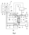
- An extracorporeal blood treatment device A is described below, which has a device for monitoring the vascular access and the extracorporeal blood circulation and the dialysis fluid system.
- a monitoring device can also be provided only for monitoring the vascular access or the extracorporeal blood circulation or the dialysis fluid system.
- Fig. 1 only shows the essential components of the blood treatment device in a schematic representation, since blood treatment devices as such are known in the art.
- the blood treatment device is a known hemodialysis device which has a dialyzer 1 which is subdivided by a semipermeable membrane 2 into a blood chamber 3 and a dialysis fluid chamber 4.
- a dialyzer 1 which is subdivided by a semipermeable membrane 2 into a blood chamber 3 and a dialysis fluid chamber 4.
- an arterial tubing 6 is connected to an arterial puncture cannula 5 and leads to the inlet of the blood chamber 3 of the dialyzer.
- From the outlet of the blood chamber 3 of the dialyzer goes from a venous tubing 7, which is connected to a venous puncture cannula 8 at the shunt or fistula.
- the blood is conveyed in the extracorporeal blood circulation I with a centrifugal pump 9, which is provided on the arterial tube 6.
- the centrifugal pump is a specially designed for blood pump, which is characterized by a low blood damage. Such pumps are state of the art.
- the dialysis fluid system II of the hemodialysis apparatus comprises a dialysis fluid source 10, to which a dialysis fluid supply line 11 is connected, which leads to the inlet of the dialysis fluid chamber 4 of the dialyzer. From the outlet of the dialysis fluid chamber 4 of the dialyzer, a dialysis fluid discharge line 12 leaves, which leads to an outlet 13.
- the dialysis fluid is conveyed in the dialysis fluid circuit with a dialysis fluid pump 14, which is arranged on the dialysis fluid discharge line 12.
- the monitoring device also serves to monitor the dialysis fluid system. Therefore, the dialysis fluid pump 14 is also a centrifugal pump.
- the control of the dialysis device takes over a central control unit 15 which controls the blood and Dialysiersammlungspumpe 9, 14 via control lines 16, 17. Downstream of the blood chamber 3 of the dialyzer is located on the venous tubing 7 a Electromagnetically actuated hose clamp 18, which can be opened or closed via a further control line 19 from the central control unit 15. When the venous hose clamp 18 is closed, the fluid flow in the extracorporeal blood circulation I is interrupted so that blood can not enter the environment.
- the monitoring device B has a control and computing unit 20, which in Fig. 1 is shown as a separate unit. But the control and processing unit 20 may also be part of the central control unit 15 of the blood treatment device.
- the monitoring device B has means for measuring the flow rate of the blood conveyed by the centrifugal pump 9 in the extracorporeal blood circulation I and means for measuring the flow rate of the dialysis fluid delivered by the centrifugal pump 14 in the dialysis fluid system II.
- the means for measuring the flow rate in the extracorporeal blood circuit I comprise a flow sensor 21A, which in the present embodiment is located downstream of the dialysis fluid chamber 3 of the dialyzer 1 and upstream of the tube clamp 18 on the venous blood line 7, while the means for measuring the flow rate of the conveyed Dialysis fluid have a flow sensor 21B, which is arranged downstream of the dialysis fluid pump 14.
- the flow sensors 21A and 21B in the present embodiment are ultrasonic flow sensors for non-invasive measurement of the flow rate of the blood and the dialysis fluid, respectively.
- the measured values of the ultrasonic flow sensors 21A and 21B are received by the control and computation unit 20 via data lines 22A and 22B.
- the control and computing unit 20 has means 20A for comparing the measured flow rate with a predetermined flow rate.
- the control and processing unit 20 has means 20B for generating a control signal which the central control unit 15 receives via a data line 23.
- a specific blood flow rate is specified by the attending physician.
- the central control unit 15 of the blood treatment apparatus adjusts the rotational speed n of the centrifugal pump 9 such that the blood in the extracorporeal blood circulation I is conveyed at the predetermined flow rate.
- the predetermined flow rate is measured by the flow sensor 21. This flow rate corresponds to the flow rate of the centrifugal pump 9, which is specified in the control and computing unit 20 as a reference value. Therefore, this flow rate is called a predetermined flow rate.
- the flow rate of the blood is now monitored continuously.
- the flow rate measured with the flow sensor 21 is continuously compared with the flow rate previously specified as the reference value.
- the difference between the measured flow rate and the predetermined flow rate is formed. If the difference is greater than a certain threshold, the control and computation unit 20 generates the control signal that the central control unit 15 receives via the data line 23.
- Fig. 2 shows the pressure difference between the inlet 9a and the outlet 9b of the centrifugal pump 9 as a function of the flow rate Q.
- the slipping out of the venous puncturing cannula 8 leads to a pressure change ⁇ P across the centrifugal pump 9 in the extracorporeal blood circulation I of 20 mmHG.
- Fig. 2 shows that at a speed n of 3000 rpm, the blood flow rate Q of 300 ml / min increases by 133 ml / min. At 4500 rpm, there is a volume flow increase of 235 ml / min.
- the two characteristic curves (curve A 4500 rpm and curve B 3000 rpm) show that even a small pressure change ⁇ P of 20 mmHG leads to a significant increase of the flow rate Q.
- the control and computation unit 20 compares the difference between the measured flow rate and the predetermined flow rate with a certain threshold. If the difference is greater than the threshold, i. there is a significant increase in flow rate, improper vascular access is assumed and the control signal is generated.
- the monitoring device B has an alarm unit 24, which receives the control signal of the control and processing unit 20 via a data line 25.
- the alarm unit 24 then gives an audible and / or visual and / or tactile alarm.
- the alarm unit can also be part of the blood treatment device.
- the monitoring device B also has an input unit 26, which is connected via a data line 27 to the control and computing unit 20.
- the input unit 26 may also be part of the blood treatment device.
- various parameters can be entered, including, for example, the data describing the tube system 6, 7 used, indicating, for example, the inner diameter, the wall thickness or the material of the hose lines.
- the data input can be done manually or automatically, for example by means of a bar code, matrix code, RFID, etc.
- the control and computing unit 20 has a memory 20C in which certain data records are assigned specific limits for monitoring the vascular access.
- the control and computation unit 20 compares the data sets input on the input unit 25 with the associated data sets and selects the limit value corresponding to the input data set. This ensures that different limits for monitoring the vascular access can be made available for different tubing.
- the limit value can in principle also be dynamically changeable.
- the limit can be fixed by the user, for example, before the start of the treatment.
- the threshold can also be adjusted during the treatment. The adjustment can also be done automatically. For example, due to changes in the viscosity of the blood or even a change in the filter properties, slow flow changes may occur. In order not to trigger an alarm in such cases, the limit can be adjusted accordingly automatically. Also, the alarm limits for abrupt changes in the flow rate can be "carried” until reaching a predetermined limit. "Predetermined” in this context means that the limit value is present or provided before it is used in the evaluation unit.
- the monitoring of the flow rate of the dialysis fluid to detect a malfunction in the dialysis fluid II is analogous to the monitoring of the blood flow rate, wherein the measured with the flow sensor 21B dialysis fluid is compared with a predetermined flow rate. If the difference between the measured and predetermined flow rate is greater than a certain threshold, it is concluded that a malfunction has occurred in the dialysis fluid system. This fault can again be in a kinked or squeezed hose line or a leak.
- the rate of change in flow rates in the tubing is monitored, where the tubing may be the arterial and venous blood lines 6, 7 or the dialysate supply or discharge line 11, 12.
- the rate of change of the flow rate is compared with a predetermined limit value.
- a fault is in particular closed in the event of a sudden change in the flow type.
- the pressure curves in the hose lines can also be monitored. Thus it can be distinguished between certain disorders, for example between a Diskonnetechnisch a cannula or leakage or the clogging of the dialyzer 1.
- pressure sensors for measuring the pressure in the hose lines are provided in a preferred embodiment.
- FIG. 1 A pressure sensor 28A for measuring the pressure in the arterial blood line 6 upstream of the blood pump 9 and a pressure sensor 28B for measuring the pressure in the arterial blood line 6 downstream of the blood pump 9 and a pressure sensor 28C for measuring the pressure in the venous blood line 7 are shown.
- the pressure sensor 28A is connected via a data line 29A
- the pressure sensor 28B is connected via a data line 29B
- the pressure sensor 28C is connected to the control and processing unit 20 via a data line 29C.
- the control and computing unit 20 is formed in the preferred embodiment such that it can be distinguished between the following cases.
- the control and computing unit closes 20 that the blood line is kinked or squashed.
- the control and computation unit closes 20 that the blood line is kinked or squashed.
- the control and computation unit 20 concludes that the dialyzer 1 is blocked.
- the control and computation unit 20 concludes that there is a disconnection of the venous cannula 8.
Landscapes
- Health & Medical Sciences (AREA)
- Heart & Thoracic Surgery (AREA)
- Vascular Medicine (AREA)
- Hematology (AREA)
- Animal Behavior & Ethology (AREA)
- Engineering & Computer Science (AREA)
- Anesthesiology (AREA)
- Biomedical Technology (AREA)
- Veterinary Medicine (AREA)
- Life Sciences & Earth Sciences (AREA)
- Public Health (AREA)
- General Health & Medical Sciences (AREA)
- Urology & Nephrology (AREA)
- Cardiology (AREA)
- Emergency Medicine (AREA)
- Physics & Mathematics (AREA)
- Fluid Mechanics (AREA)
- External Artificial Organs (AREA)
- Measuring Pulse, Heart Rate, Blood Pressure Or Blood Flow (AREA)
Abstract
Description
- Die Erfindung betrifft eine Vorrichtung zur Überwachung einer extrakorporalen Blutbehandlungsvorrichtung mit einem extrakorporalen Blutkreislauf. Darüber hinaus betrifft die Erfindung eine extrakorporale Blutbehandlungsvorrichtung mit einer derartigen Überwachungsvorrichtung.
- Auf dem Gebiet der Medizintechnik sind verschiedene extrakorporale Blutbehandlungsvorrichtungen bekannt, die über einen extrakorporalen Blutkreislauf verfügen. Zu den bekannten extrakorporalen Blutbehandlungsvorrichtungen zählen beispielsweise Hämodialysevorrichtungen und Zellseparatoren, die einen Zugang zu dem Gefäßsystem des Patienten erforderlich machen. Bei der extrakorporalen Blutbehandlung wird dem Patienten über eine arterielle Schlauchleitung mit einer arteriellen Punktionskanüle Blut entnommen, das dem Patienten über eine venöse Schlauchleitung mit einer venösen Punktionskanüle wieder zugeführt wird.
- Zum Fördern des Bluts im extrakorporalen Blutkreislauf verfügen die extrakorporalen Blutbehandlungsvorrichtungen im Allgemeinen über eine okkludierende Schlauchpumpe, insbesondere eine Rollenpumpe. Okkludierende Schlauchpumpen sind im Allgemeinen auch im Dialysierflüssigkeitssystem der extrakorporalen Blutbehandlungsvorrichtungen vorgesehen. Aus anderen medizinischen Fachgebieten, beispielsweise bei Bypass-Operationen am Herz, sind für den Betrieb eines extrakorporalen Blutkreislaufs auch andere Blutpumpen bekannt, insbesondere spezielle für Blut ausgelegte Zentrifugalpumpen, die sich durch eine verhältnismäßig geringe Blutschädigung auszeichnen.
- Bei der extrakorporalen Blutbehandlung besteht trotz regelmäßiger Überwachung des Gefäßzugangs durch das Krankenhauspersonal grundsätzlich die Gefahr, dass die venöse Punktionskanüle unbemerkt aus dem Blutgefäß des Patienten herausrutscht. Während ein Herausrutschen der arteriellen Kanüle mit einem Ansaugen von Luft in die arterielle Schlauchleitung verbunden ist, führt das Herausrutschen der venösen Kanüle zu dem gefürchteten Freifluss des Blutes in die Umgebung. Wenn das Herausrutschen der venösen Kanüle daher nicht sofort erkannt wird, besteht die Gefahr, dass der Patient verblutet.
- Zur Überwachung des Gefäßzugangs sind verschiedene Vorrichtungen unterschiedlicher Ausbildungen bekannt. Die bekannten Überwachungsvorrichtungen greifen im Allgemeinen auf die standardmäßig in den Blutbehandlungsvorrichtungen vorhandenen Sicherheitsvorrichtungen zurück, die bei einem nicht ordnungsgemäßen Gefäßzugang eine sofortige Unterbrechung des Blutflusses im extrakorporalen Blutkreislauf auslösen.
- Aus der
WO 99/29356 A1 US 2004/0254513 A1 beschreibt eine Überwachungsvorrichtung, bei der die Impedanz zwischen zwei an der arteriellen und venösen Schlauchleitung angeordneten Elektroden gemessen wird. Nachteilig ist, dass die bekannten Vorrichtungen die Schaffung einer elektrischen Verbindung zu der in den Schlauchleitungen strömenden Flüssigkeit erfordern. - Zur Überwachung sowohl des arteriellen als auch des venösen Gefäßzugangs sind auch Überwachungssysteme bekannt, die auf einer Messung des Drucks im extrakorporalen Blutkreislauf beruhen. Beim Herausrutschen der venösen Punktionskanüle kann in der Praxis eine Druckabnahme von 20 mmHG angenommen werden. Da der Nennwert der Messwertauflösung in der Praxis im Bereich von 2 mmHG mit einem maximalen Gesamtfehler zwischen 15 und 20 mmHG liegt, erweist sich die Detektion einer venösen Diskonnektion als schwierig. Ein Überwachungssystem mit einer Drucküberwachung ist bespielsweise aus der
US 6221040 B1 bekannt. Die bekannte Drucküberwachung macht von einem speziellen Auswertverfahren Gebrauch. - Aus der
WO 2006/008866 A1 undUS 2005/0038325 A1 sind Überwachungsvorrichtungen bekannt, die den Austritt von Blut an der Punktionsstelle detektieren können. Diese Vorrichtungen verfügen über einen Feuchtigkeitssensor. - Der Erfindung liegt die Aufgabe zu Grunde, einen Gefäßzugang und/oder einen extrakorporalen Blutkreislauf und/oder ein Dialysierflüssigkeitssystem einer extrakorporalen Blutbehandlungsvorrichtung ohne umfangreiche Veränderungen an der Blutbehandlungsvorrichtung und ohne die Verwendung separater Komponenten mit besonders hoher Zuverlässigkeit zu überwachen.
- Die Lösung dieser Aufgabe erfolgt erfindungsgemäß mit den Merkmalen der unabhängigen Patentansprüche. Vorteilhafte Ausführungsformen der Erfindung sind Gegenstand der Unteransprüche.
- Die erfindungsgemäße Vorrichtung beruht auf der Verwendung einer Zentrifugalpumpe zum Fördern von Blut im extrakorporalen Blutkreislauf oder von Dialysierflüssigkeit im Dialysierflüssigkeitssystem anstelle einer okkludierenden Pumpe. Die Zentrifugalpumpe, die auch unter der Bezeichnung Kreiselpumpe bekannt ist, verfügt über ein rotierendes Pumpenrad zur Förderung von Flüssigkeiten. Die Flüssigkeit, die über das Saugrohr in die Zentrifugalpumpe eintritt, wird vom rotierenden Pumpenrad gefördert und auf einer Kreisbahn nach außen gezwungen. Die dabei aufgenommene Bewegungsenergie der Flüssigkeit erhöht den Druck innerhalb der Pumpe und presst die Flüssigkeit in das Druckrohr.
- Die Erfindung macht von den besonderen Eigenschaften der bekannten Zentrifugalpumpen Gebrauch, wenn sie zur Förderung von Blut und/oder Dialysierflüssigkeit Verwendung finden. Diese Zentrifugalpumpen zeichnen sich dadurch aus, dass eine schon kleine Änderung der Druckdifferenz über der Pumpe eine große Änderung der Flussrate bewirkt. Wenn nachfolgend von der Flussrate die Rede ist, wird darunter auch jede andere mit der Flussrate korrelierende Größe verstanden, die sich gleichsam mit der Zunahme der Flussrate erhöht.
- Die erfindungsgemäße Vorrichtung verfügt über Mittel zum Messen der Flussrate des mit der Zentrifugalpumpe im extrakorporalen Blutkreislauf geförderten Bluts und/oder der Dialysierflüssigkeit im Dialysierflüssigkeitssystem sowie einer Steuer- und Recheneinheit, die derart ausgebildet ist, dass bei einer Änderung der gemessenen Flussrate um mehr als einen vorbestimmten Betrag auf einen nicht ordnungsgemäßen Gefäßzugang oder eine Störung im extrakorporalen Blutkreislauf oder Dialysierflüssigkeitssystem geschlossen wird. Kommt es während der extrakorporalen Blutbehandlung beispielsweise zu einem geringen Druckabfall in der venösen Blutleitung führt dies zu einem deutlichen Anstieg der Flussrate der Zentrifugalpumpe. Dieser signifikante und plötzliche Anstieg der Flussrate, die sich aus der charakteristischen flachen Förderkennlinie der Zentrifugalpumpe ergibt, wird erfindungsgemäß als Grundlage für die Erkennung eines nicht ordnungsgemäßen venösen Gefäßzugangs verwandt. Mit der Überwachung der Flussrate der Zentrifugalpumpe kann nicht nur das Herausrutschen einer der beiden Punktionskanülen aus dem Gefäßsystem des Patienten, sondern auch ein Quetschen, Knicken der Blutleit- oder Dialysierflüssigkeitsleitungen und eine Leckage der Schlauchleitungen erkannt werden. Die Flussrate kann grundsätzlich an einer beliebigen Stelle im extrakorporalen Blutkreislauf oder Dialysierflüssigkeitssystem gemessen werden.
- Von Vorteil ist, dass die erfindungsgemäße Vorrichtung nicht von externen Komponenten Gebrauch machen, die zusätzliche Handgriffe erfordern oder die Bewegungsfreiheit des Patienten unnötig einschränken.
- Bei einer bevorzugten Ausführungsform der Erfindung weist die Steuer- und Recheneinheit Mittel zum Vergleichen der gemessenen Flussrate mit einer vorgegebenen Flussrate und Mittel zum Erzeugen eines Steuersignals auf, wenn die Differenz von der gemessenen Flussrate und der vorgegebenen Flussrate größer als ein bestimmter Grenzwert ist. Dieser Grenzwert ist von verschiedenen Faktoren abhängig. Beispielsweise ist der Grenzwert von der Beschaffenheit der Schlauchleitungen abhängig. In Abhängigkeit von den verschiedenen Faktoren können verschiedene Grenzwerte vorgegeben werden. Eine bevorzugte Ausführungsform sieht die Eingabe von Datensätzen auf einer Eingabeeinheit vor, die für die unterschiedlichen Faktoren, beispielsweise für das verwendete Schlauchset, charakteristisch sind. Diese Datensätze werden mit gespeicherten Datensätzen verglichen, denen bestimmte Grenzwerte zugeordnet sind, um denjenigen Grenzwert auswählen zu können, der dem eingegebenen Datensatz entspricht.
- Die Überwachungsvorrichtung weist vorzugsweise eine Alarmeinheit auf, die einen akustischen und/oder optischen und/oder taktilen Alarm gibt, wenn die Steuer- und Recheneinheit das Steuersignal erzeugt.
- Die Mittel zum Messen der Flussrate weisen vorzugsweise einen Flusssensor zur nicht-invasiven Messung der Blutflussrate auf. Vorzugsweise ist der Flusssensor ein Ultraschall-Flusssensor, der nach dem bekannten Ultraschall-Dopplerverfahren oder Laufzeit-Differenzverfahren die Flussrate arbeitet. Derartige Ultraschall-Flusssensoren sind dem Fachmann bekannt. Es sind aber auch alle anderen dem Fachmann bekannten Verfahren zur Messung der Flussrate einsetzbar, beispielsweise die Auswertung der Motordaten der Zentrifugalpumpe, eine magnetisch-induktive Durchflussmessung oder eine optische Durchflussmessung mit einem Laser. Für Messungen der Flussrate im Dialysierflüssigkeitssystem hingegen kann die Messung der Flussarte auch invasiv erfolgen. Dafür können alle dem Fachmann bekannten Flussmesser Verwendung finden.
- Der Flusssensor kann prinzipiell an jeder Stelle im extrakorporalen Blutkreislauf oder des Dialysierflüssigkeistsystems, insbesondere an der arteriellen oder venösen Blutleitung bzw. der Dialysierflüssigkeitszuführ und -abführleitung angeordnet sein. Insbesondere kann der Flusssensor in die bei Blutbehandlungsvorrichtungen standardmäßig vorhandene Vorrichtung zur arteriellen Luftblasenerkennung integriert sein.
- Die erfindungsgemäße Vorrichtung zur extrakorporalen Blutbehandlung verfügt über die erfindungsgemäße Überwachungsvorrichtung. Eine bevorzugte Ausführungsform der erfindungsgemäßen Blutbehandlungsvorrichtung sieht vor, dass die Steuereinheit der Blutbehandlungsvorrichtung einen Eingriff in die Maschinensteuerung vornimmt, wenn die Steuer- und Recheneinheit der Überwachungsvorrichtung ein Steuersignal erzeugt. Vorzugsweise ist die Steuereinheit derart ausgebildet, dass als Eingriff in die Maschinensteuerung die im extrakorporalen Blutkreislauf angeordnete Zentrifugalpumpe angehalten wird. Darüber hinaus wird vorzugsweise mindestens ein in oder an der venösen Blutleitung angeordnetes Absperrorgan geschlossen. Vorzugsweise wird sowohl die arterielle als venöse Schlauchklemme geschlossen. Dadurch wird bei einem nicht ordnungsgemäßen Gefäßzugang, beispielsweise wenn die venöse Punktionskanüle herausgerutscht ist oder eine Leckage im Schlauchsystem vorliegt, der Freifluss von Blut in die Umgebung sofort gestoppt.
- Im Folgenden wird ein Ausführungsbeispiel der Erfindung unter Bezugnahme auf die Zeichnungen näher erläutert.
- Es zeigen:
- Fig. 1
- die wesentlichen Komponenten einer erfindungsgemäßen extrakorporalen Blutbehandlungsvorrichtung mit einer erfindungsgemäßen Vorrichtung zur Überwachung eines Gefäßzugangs oder des extrakorporalen Blutkreislaufs oder Dialysierflüssigkeitssystems und
- Fig. 2
- der prinzipielle Verlauf der Druckdifferenz über der im extrakorporalen Blutkreislauf vorgesehenen Zentrifugalpumpe in Abhängigkeit vom Blutfluss.
- Die erfindungsgemäße Vorrichtung zur Überwachung eines Gefäßzugangs oder des extrakorporalen Blutkreislaufs oder Dialysierflüssigkeitssystems kann eine separate Einheit bilden oder auch Bestandteil der extrakorporalen Blutbehandlungsvorrichtung sein. Wenn die erfindungsgemäße Überwachungsvorrichtung Bestandteil der Blutbehandlungsvorrichtung ist, kann die erfindungsgemäße Überwachungsvorrichtung von bestimmten Baugruppen oder Bauteilen Gebrauch machen, die in der Blutbehandlungsvorrichtung ohnehin vorhanden sind.
- Nachfolgend wird eine extrakorporale Blutbehandlungsvorrichtung A beschrieben, die über eine Vorrichtung zur Überwachung des Gefäßzugangs und des extrakorporalen Blutkreislaufs und des Dialysierflüssigkeitssystems verfügt. Es kann aber auch eine Überwachungsvorrichtung nur zur Überwachung des Gefäßzugangs oder des extrakorporalen Blutkreislaufs oder des Dialysierflüssigkeitssystems vorgesehen sein.
Fig. 1 zeigt nur die wesentlichen Komponenten der Blutbehandlungsvorrichtung in schematischer Darstellung, da Blutbehandlungsvorrichtungen als solche dem Fachmann bekannt sind. - Bei der Blutbehandlungsvorrichtung handelt es sich um eine bekannte Hämodialysevorrichtung, die einen Dialysator 1 aufweist, der durch eine semipermeable Membran 2 in eine Blutkammer 3 und eine Dialysierflüssigkeitskammer 4 unterteilt ist. An dem Shunt oder einer Fistel des Patienten ist mit einer arteriellen Punktionskanüle 5 eine arterielle Schlauchleitung 6 angeschlossen, die zum dem Einlass der Blutkammer 3 des Dialysators führt. Von dem Auslass der Blutkammer 3 des Dialysators geht eine venöse Schlauchleitung 7 ab, die mit einer venösen Punktionskanüle 8 an dem Shunt oder der Fistel angeschlossen ist. Das Blut wird im extrakorporalen Blutkreislauf I mit einer Zentrifugalpumpe 9 gefördert, die an der arteriellen Schlauchleitung 6 vorgesehen ist. Bei der Zentrifugalpumpe handelt es sich um eine speziell für Blut ausgelegte Pumpe, die sich durch eine geringe Blutschädigung auszeichnet. Derartige Pumpen gehören zum Stand der Technik.
- Das Dialysierflüssigkeitssystem II der Hämodialysevorrichtung umfasst eine Dialysierflüssigkeitsquelle 10, an der eine Dialysierflüssigkeitszuführleitung 11 angeschlossen ist, die zu dem Einlass der Dialysierflüssigkeitskammer 4 des Dialysators führt. Von dem Auslass der Dialysierflüssigkeitskammer 4 des Dialysators geht eine Dialysierflüssigkeitsabführleitung 12 ab, die zu einem Auslass 13 führt. Die Dialysierflüssigkeit wird im Dialysierflüssigkeitskreislauf mit einer Dialysierflüssigkeitspumpe 14 gefördert, die an der Dialysierflüssigkeitsabführleitung 12 angeordnet ist. Bei dem vorliegenden Ausführungsbeispiel dient die Überwachungsvorrichtung auch der Überwachung des Dialysierflüssigkeitssystems. Daher handelt es sich auch bei der Dialysierflüssigkeitspumpe 14 um eine Zentrifugalpumpe. Dies ist aber nicht erforderlich, wenn die Überwachungsvorrichtung nur der Überwachung des Gefäßzugangs oder exktrakorporalen Blutkreislaufs dient.
Die Steuerung der Dialysevorrichtung übernimmt eine zentrale Steuereinheit 15, die über Steuerleitungen 16, 17 die Blut- und Dialysierflüssigkeitspumpe 9, 14 ansteuert. Stromab der Blutkammer 3 des Dialysators befindet sich an der venösen Schlauchleitung 7 eine elektromagnetisch betätigbare Schlauchklemme 18, die über eine weitere Steuerleitung 19 von der zentralen Steuereinheit 15 geöffnet bzw. geschlossen werden kann. Bei geschlossener venöser Schlauchklemme 18 ist die Flüssigkeitsströmung im extrakorporalen Blutkreislauf I unterbrochen, so dass Blut nicht in die Umgebung gelangen kann. - Die Überwachungsvorrichtung B verfügt über eine Steuer- und Recheneinheit 20, die in
Fig. 1 als separate Einheit dargestellt ist. Die Steuer- und Recheneinheit 20 kann aber auch Bestandteil der zentralen Steuereinheit 15 der Blutbehandlungsvorrichtung sein. - Darüber hinaus verfügt die Überwachungsvorrichtung B über Mittel zum Messen der Flussrate des mit der Zentrifugalpumpe 9 im extrakorporalen Blutkreislauf I geförderten Bluts und Mittel zum Messen der Flussrate der mit der Zentrifugalpumpe 14 im Dialysierflüssigkeitssystem II geförderten Dialysierflüssigkeit. Die Mittel zum Messen der Flussrate im extrakorporalen Blutkreislauf I weisen einen Flusssensor 21A auf, der bei dem vorliegenden Ausführungsbeispiel stromab der Dialysierflüssigkeitskammer 3 des Dialysators 1 und stromauf der Schlauchklemme 18 an der venösen Blutleitung 7 angeordnet ist, während die Mittel zum Messen der Flussrate der geförderten Dialysierflüssigkeit einen Flusssensor 21B aufweisen, der stromab der Dialysierflüssigkeispumpe 14 angeordnet ist. Die Flusssensoren 21A und 21B sind bei dem vorliegenden Ausführungsbeispiel Ultraschall-Flusssensoren zur nicht-invasiven Messung der Flussrate des Bluts bzw. der Dialysierflüssigkeit. Die Messwerte der Ultraschall-Flusssensoren 21A und 21B empfängt die Steuer- und Recheneinheit 20 über Datenleitungen 22A und 22B.
- Die Steuer- und Recheneinheit 20 weist Mittel 20A zum Vergleichen der gemessenen Flussrate mit einer vorgegebenen Flussrate auf. Darüber hinaus weist die Steuer- und Recheneinheit 20 Mittel 20B zum Erzeugen eines Steuersignals auf, das die zentrale Steuereinheit 15 über eine Datenleitung 23 empfängt.
Für die extrakorporale Blutbehandlung wird eine bestimmte Blutflussrate vom behandelnden Arzt vorgegeben. Die zentrale Steuereinheit 15 der Blutbehandlungsvorrichtung stellt die Drehzahl n der Zentrifugalpumpe 9 derart ein, dass das Blut im extrakorporalen Blutkreislauf I mit der vorgegebenen Flussrate gefördert wird. Die vorgegebene Flussrate wird von dem Flusssensor 21 gemessen. Diese Flussrate entspricht der Flussrate der Zentrifugalpumpe 9, die in der Steuer- und Recheneinheit 20 als Referenzwert vorgegeben wird. Daher wird diese Flussrate als vorgegebene Flussrate bezeichnet. Während der extrakorporalen Blutbehandlung wird nunmehr die Flussrate des Bluts laufend überwacht. Die mit dem Flusssensor 21 gemessene Flussrate wird mit der zuvor als Referenzwert vorgegebenen Flussrate laufend vergleichen. Es wird die Differenz zwischen der gemessenen Flussrate und der vorgegebenen Flussrate gebildet. Wenn die Differenz größer als ein bestimmter Grenzwert ist, erzeugt die Steuer- und Recheneinheit 20 das Steuersignal, das die zentrale Steuereinheit 15 über die Datenleitung 23 empfängt. -
Fig. 2 zeigt die Druckdifferenz zwischen dem Einlass 9a und dem Auslass 9b der Zentrifugalpumpe 9 als Funktion der Flussrate Q. Das Herausrutschen der venösen Punktionskanüle 8 führt zu einer Druckänderung ΔP über der Zentrifugalpumpe 9 im extrakorporalen Blutkreislauf I von 20 mmHG.Fig. 2 zeigt, dass bei einer Drehzahl n von 3000 U/min die Blutflussrate Q von 300 ml/min um 133 ml/min zunimmt. Bei 4500 U/min zeigt sich eine Volumenstromzunahme von 235 ml/min. Die beiden Kennlinien (Kennlinie A 4500 U/min und Kennlinie B 3000 U/min) zeigen, dass auch eine geringe Druckänderung ΔP von 20 mmHG zu einem signifikanten Anstieg der Flussrate Q führt. - Die Steuer- und Recheneinheit 20 vergleicht die Differenz zwischen der gemessenen Flussrate und der vorgegebenen Flussrate mit einem bestimmten Grenzwert. Wenn die Differenz größer als der Grenzwert ist, d.h. ein signifikanter Anstieg der Flussrate zu verzeichnen ist, wird ein nicht ordnungsgemäßer Gefäßzugang angenommen und das Steuersignal erzeugt.
- Die Überwachungsvorrichtung B weist eine Alarmeinheit 24 auf, die das Steuersignal der Steuer- und Recheneinheit 20 über eine Datenleitung 25 empfängt. Die Alarmeinheit 24 gibt dann einen akustischen und/oder optischen und/oder taktilen Alarm. Die Alarmeinheit kann aber auch Bestandteil der Blutbehandlungsvorrichtung sein. Wenn die zentrale Steuereinheit 15 der Blutbehandlungsvorrichtung das Steuersignal der Steuer- und Recheneinheit 20 empfängt, hält die zentrale Steuereinheit 15 die Zentrifugalpumpe 9 sofort an und schließt sofort die Schlauchklemme 18, so dass der Freifluss von Blut in die Umgebung sofort gestoppt wird.
- Die Überwachungsvorrichtung B weist auch eine Eingabeeinheit 26 auf, die über eine Datenleitung 27 mit der Steuer- und Recheneinheit 20 verbunden ist. Die Eingabeeinheit 26 kann ebenfalls Bestandteil der Blutbehandlungsvorrichtung sein.
- Auf der Eingabeeinheit 25 der Überwachungsvorrichtung B können verschiedene Parameter eingegeben werden, zu denen beispielsweise die das verwendete Schlauchsystem 6, 7 beschreibende Daten gehören, die beispielsweise den Innendurchmesser, die Wandstärke oder den Werkstoff der Schlauchleitungen angeben. Die Dateneingabe kann manuell oder automatisch erfolgen, beispielsweise mittels eines Bar-Code, Matrix-Code, RFID etc. Die Steuer- und Recheneinheit 20 weist einen Speicher 20C auf, in dem verschiedenen Datensätzen bestimmte Grenzwerte für die Überwachung des Gefäßzugangs zugeordnet sind. Die Steuer- und Recheneinheit 20 vergleicht die auf der Eingabeeinheit 25 eingegebenen Datensätze mit den zugeordneten Datensätzen und wählt den Grenzwert aus, der dem eingegebenen Datensatz entspricht. Dadurch wird sichergestellt, dass für unterschiedliche Schlauchleitungen unterschiedliche Grenzwerte für die Überwachung des Gefäßzugangs zur Verfügung gestellt werden können.
- Der Grenzwert kann grundsätzlich auch dynamisch veränderlich sein. Einerseits kann der Grenzwert vom Benutzer beispielsweise vor Beginn der Behandlung fest vorgegeben werden. Andererseits kann der Grenzwert auch während der Behandlung angepasst werden. Die Anpassung kann auch automatisch erfolgen. Beispielsweise kann es aufgrund von Viskositätsänderungen des Bluts oder auch einer Änderung der Filtereigenschaften zu langsamen Flussänderungen kommen. Um in solchen Fällen keinen Alarm auszulösen kann der Grenzwert dementsprechend automatisch angepasst werden. Auch die Alarmgrenzen für abrupte Änderungen der Flussrate können bis zum Erreichen einer vorgegebenen Grenze "mitgeführt" werden. Unter "vorbestimmt" ist in diesem Zusammenhang zu verstehen, dass der Grenzwert vor seiner Verwendung in der Auswerteeinheit vorliegt bzw. bereitgestellt ist.
- Die Überwachung der Flussrate der Dialysierflüssigkeit zur Erkennung einer Störung im Dialysierflüssigkeitssystem II erfolgt analog zu der Überwachung der Blutflussrate, wobei die mit dem Flusssensor 21B gemessene Dialysierflüssigkeitsrate mit einer vorgegebenen Flussrate verglichen wird. Wenn die Differenz zwischen der gemessenen und vorgegebenen Flussrate größer als ein bestimmter Grenzwert ist, wird auf einen Störfall im Dialysierflüssigkeitssystem geschlossen. Dieser Störfall kann wieder in einer abgeknickten oder abgequetschten Schlauchleitung oder einer Leckage liegen.
- Bei einer bevorzugten Ausführungform wird die Geschwindigkeit der Änderung der Flussraten in den Schlauchleitungen überwacht, wobei es sich bei den Schlauchleitungen um die arterielle und venöse Blutleitung 6, 7 oder die Dialysierflüssigkeitszuführ oderabführleitung 11, 12 handeln kann. Dabei wird die Geschwindigkeit der Änderung der Flussrate mit einem vorgegeben Grenzwert verglichen. Auf eine Störung wird insbesondere bei einer plötzlichen Änderung der Flussarte geschlossen. Zusätzlich zu der Überwachung der Flussraten können auch die Druckverläufe in den Schlauchleitungen überwacht werden. Damit kann zwischen bestimmten Störungen, beispielsweise zwischen einer Diskonnektion einer Kanüle oder einer Leckage oder dem Verstopfen des Dialysators 1 unterschieden werden. Hierzu sind bei einer bevorzugten Ausführungsform Drucksensoren zum Messen des Drucks in den Schlauchleitungen vorgesehen.
- In
Fig. 1 ist ein Drucksensor 28A zum Messen des Drucks in der arteriellen Blutleitung 6 stromauf der Blutpumpe 9 und ein Drucksensor 28B zum Messen des Drucks in der arteriellen Blutleitung 6 stromab der Blutpumpe 9 sowie ein Drucksensor 28C zum Messen des Drucks in der venösen Blutleitung 7 gezeigt. Der Drucksensor 28A ist über eine Datenleitung 29A, der Drucksensor 28B ist über eine Datenleitung 29B und der Drucksensor 28C ist über eine Datenleitung 29C mit der Steuer- und Recheneinheit 20 verbunden. - Die Steuer- und Recheneinheit 20 ist bei der bevorzugten Ausführungsform derart ausgebildet, dass zwischen den nachfolgend genannten Fällen unterschieden werden kann. Wenn die mit dem Flusssensor 21A gemessene Blutflussrate im extrakorporalen Blutkreislauf I mit einer Geschwindigkeit sinkt, die größer als ein vorgegebener erster Grenzwert ist, und der mit dem Drucksensor 28A stromauf der Blutpumpe 9 gemessene Druck unter einen vorgegeben Grenzwert sinkt, schließt die Steuer- und Recheneinheit 20 darauf, dass die Blutleitung geknickt oder gequetscht ist.
- Wenn die mit dem Flusssensor 21A gemessene Blutflussrate im extrakorporalen Blutkreislauf I mit einer Geschwindigkeit sinkt, die größer als ein vorgegebener zweiter Grenzwert ist, und der mit dem Drucksensor 28B stromab der Blutpumpe 9 gemessene Druck über einen vorgegeben Grenzwert ansteigt, schließt die Steuer- und Recheneinheit 20 darauf, dass die Blutleitung geknickt oder gequetscht ist.
- Wenn die mit dem Flusssensor 21A gemessene Blutflussrate im extrakorporalen Blutkreislauf I mit einer Geschwindigkeit sinkt, die größer als ein vorgegebener dritter Grenzwert ist, welcher kleiner als der oben genannte erste Grenzwert ist, d.h. die Flussrate langsamer sinkt, und der mit dem Drucksensor 28B stromab der Blutpumpe 9 gemessene Druck über einen vorgegeben Grenzwert ansteigt, schließt die Steuer- und Recheneinheit 20 darauf, dass der Dialysator 1 verstopft ist.
- Wenn die mit dem Flusssensor 21A gemessene Blutflussrate im extrakorporalen Blutkreislauf I mit einer Geschwindigkeit ansteigt, die größer als ein vorgegebener vierter Grenzwert ist, d.h. die Flussrate schnell ansteigt, und der mit dem Drucksensor 28C in der venösen Blutleitung 7 gemessene Druck konstant bleibt oder fällt, schließt die Steuer- und Recheneinheit 20 darauf, dass eine Diskonnektion der venösen Kanüle 8 vorliegt.
Claims (13)
- Vorrichtung zur Überwachung einer extrakorporalen Blutbehandlungsvorrichtung mit einem extrakorporalen Blutkreislauf, der eine arterielle Blutleitung mit einem arteriellen Patientenanschluss und eine venöse Blutleitung mit einem venösen Patientenanschluss aufweist, und mit einem Dialysierflüssigkeitssystem, wobei in der arteriellen oder venösen Blutleitung des extraorporalen Blutkreislaufs eine Zentrifugalpumpe zum Fördern von Blut im extrakorporalen Blutkreislauf angeordnet ist,
dadurch gekennzeichnet, dass
die Überwachungsvorrichtung aufweist:Mittel (21) zum Messen der Flussrate Q des mit der Zentrifugalpumpe im extrakorporalen Blutkreislauf geförderten Bluts, undeine Steuer- und Recheneinheit (20), die derart ausgebildet ist, dass bei einer Änderung der gemessenen Flussrate um mehr als einen vorbestimmten Betrag auf eine Störung im extrakorporalen Blutkreislauf geschlossen wird. - Vorrichtung zur Überwachung einer extrakorporalen Blutbehandlungsvorrichtung mit einem extrakorporalen Blutkreislauf, und mit einem Dialysierflüssigkeitssystem, das eine Dialysierflüssigkeitszuführleitung und eine Dialysierflüssigkeitsabführleitung aufweist, wobei in der Dialysierflüssigkeitszuführleitung oder der Dialysierflüssigkeitsabführleitung des Dialysierflüssigkeitssystems eine Zentrifugalpumpe zum Fördern von Dialysierflüssigkeit angeordnet ist,
dadurch gekennzeichnet, dass
die Überwachungsvorrichtung aufweist:Mittel (21) zum Messen der Flussrate Q der mit der Zentrifugalpumpe im Dialysierflüssigkeitssystem geförderten Dialysierflüssigkeit, undeine Steuer- und Recheneinheit (20), die derart ausgebildet ist, dass bei einer Änderung der gemessenen Flussrate um mehr als einen vorbestimmten Betrag auf eine Störung im Dialysierflüssigkeitssystem geschlossen wird. - Vorrichtung nach Anspruch 1 oder 2, dadurch gekennzeichnet, dass die Steuer- und Recheneinheit (20) Mittel (20A) zum Vergleichen der gemessenen Flussrate mit einer vorgegebenen Flussrate und Mittel (20B) zum Erzeugen eines Steuersignals aufweist, wenn die Differenz von der gemessenen Flussrate und der vorgegebenen Flussrate größer als ein bestimmter Grenzwert ist.
- Vorrichtung nach Anspruch 3 dadurch gekennzeichnet, dass die Überwachungsvorrichtung eine Alarmeinheit (24) aufweist, die einen akustischen und/oder optischen und/oder taktilen Alarm gibt, wenn die Steuer- und Recheneinheit (20) das Steuersignal erzeugt.
- Vorrichtung nach einem der Ansprüche 1 bis 4, dadurch gekennzeichnet, dass die Mittel zum Messen der Flussrate des mit der Zentrifugalpumpe im extrakorporalen Blutkreislauf geförderten Bluts einen Flusssensor (21) zur nicht-invasiven Messung der Flussrate des Bluts in der arteriellen oder venösen Blutleitung aufweisen.
- Vorrichtung nach Anspruch 5, dadurch gekennzeichnet, dass der Flusssensor zur nicht-invasiven Messung der Flussrate des Bluts ein Ultraschall-Flusssensor (21) ist.
- Vorrichtung nach einem der Ansprüche 1 bis 6, dadurch gekennzeichnet, dass die Überwachungsvorrichtung eine Eingabeeinheit (26) zur Eingabe von Datensätzen aufweist, wobei die Steuer- und Recheneinheit (20) einen Speicher (20C) aufweist, in dem einzelnen Datensätzen bestimmte Grenzwerte zugeordnet sind.
- Vorrichtung zur extrakorporalen Blutbehandlung mit einem extrakorporalen Blutkreislauf (I), der eine arterielle Blutleitung (6) mit einem arteriellen Patientenanschluss (5) und eine venöse Blutleitung (7) mit einem venösen Patientenanschluss (8) aufweist, wobei in der arteriellen oder venösen Blutleitung eine Zentrifugalpumpe (9) zum Fördern von Blut im extrakorporalen Blutkreislauf angeordnet ist, dadurch gekennzeichnet, dass die extrakorporale Blutbehandlungsvorrichtung eine Überwachungsvorrichtung (B) nach einem der Ansprüche 1 bis 7 aufweist.
- Vorrichtung zur extrakorporalen Blutbehandlung mit einem extrakorporalen Blutkreislauf (I), und mit einem Dialysierflüssigkeitssystem (II), das eine Dialysierflüssigkeitszuführleitung (11) und eine Dialysierflüssigkeitsabführleitung (12) aufweist, wobei in der Dialysierflüssigkeitszuführleitung oder der Dialysierflüssigkeitsabführleitung des Dialysierflüssigkeitssystems eine Zentrifugalpumpe (14) zum Fördern von Dialysierflüssigkeit angeordnet ist, dadurch gekennzeichnet, dass die extrakorporale Blutbehandlungsvorrichtung eine Überwachungsvorrichtung (B) nach einem der Ansprüche 1 bis 7 aufweist.
- Vorrichtung nach Anspruch 8 oder 9, dadurch gekennzeichnet, dass die extrakorporale Blutbehandlungsvorrichtung eine zentrale Steuereinheit (15) aufweist, die derart ausgebildet ist, dass die Steuereinheit einen Eingriff in die Maschinensteuerung vornimmt, wenn die Steuer- und Recheneinheit (20) der Überwachungsvorrichtung ein Steuersignal erzeugt.
- Vorrichtung nach Anspruch 10, dadurch gekennzeichnet, dass die Steuereinheit (15) der Blutbehandlungsvorrichtung (A) derart ausgebildet ist, dass als Eingriff in die Maschinensteuerung die im extrakorporalen Blutkreislauf (I) angeordnete Zentrifugalpumpe (9) angehalten wird.
- Vorrichtung nach Anspruch 10 oder 11, dadurch gekennzeichnet, dass die Steuereinheit (15) der Blutbehandlungsvorrichtung (A) derart ausgebildet ist, dass als Eingriff in die Maschinensteuerung ein in oder an der venösen Blutleitung (7) angeordnetes Absperrorgan (18) geschlossen wird.
- Vorrichtung nach einem der Ansprüche 8 bis 12, dadurch gekennzeichnet, dass die Zentrifugalpumpe (9) in der arteriellen Blutleitung (7) angeordnet ist.
Applications Claiming Priority (3)
| Application Number | Priority Date | Filing Date | Title |
|---|---|---|---|
| DE102009060668A DE102009060668A1 (de) | 2009-12-28 | 2009-12-28 | Vorrichtung und Verfahren zur Überwachung einer extrakorporalen Blutbehandlung |
| PCT/EP2010/007948 WO2011079941A1 (de) | 2009-12-28 | 2010-12-27 | Vorrichtung und verfahren zur überwachung einer extrakorporalen blutbehandlung |
| EP10801147.9A EP2519282B1 (de) | 2009-12-28 | 2010-12-27 | Vorrichtung und verfahren zur überwachung einer extrakorporalen blutbehandlung |
Related Parent Applications (1)
| Application Number | Title | Priority Date | Filing Date |
|---|---|---|---|
| EP10801147.9A Division EP2519282B1 (de) | 2009-12-28 | 2010-12-27 | Vorrichtung und verfahren zur überwachung einer extrakorporalen blutbehandlung |
Publications (2)
| Publication Number | Publication Date |
|---|---|
| EP3141272A1 true EP3141272A1 (de) | 2017-03-15 |
| EP3141272B1 EP3141272B1 (de) | 2019-07-24 |
Family
ID=43806771
Family Applications (2)
| Application Number | Title | Priority Date | Filing Date |
|---|---|---|---|
| EP16194248.7A Not-in-force EP3141272B1 (de) | 2009-12-28 | 2010-12-27 | Vorrichtung zur überwachung einer extrakorporalen blutbehandlungsvorrichtung und vorrichtung zur extrakorporalen blutbehandlung |
| EP10801147.9A Not-in-force EP2519282B1 (de) | 2009-12-28 | 2010-12-27 | Vorrichtung und verfahren zur überwachung einer extrakorporalen blutbehandlung |
Family Applications After (1)
| Application Number | Title | Priority Date | Filing Date |
|---|---|---|---|
| EP10801147.9A Not-in-force EP2519282B1 (de) | 2009-12-28 | 2010-12-27 | Vorrichtung und verfahren zur überwachung einer extrakorporalen blutbehandlung |
Country Status (5)
| Country | Link |
|---|---|
| US (2) | US10022485B2 (de) |
| EP (2) | EP3141272B1 (de) |
| JP (2) | JP5840622B2 (de) |
| DE (1) | DE102009060668A1 (de) |
| WO (1) | WO2011079941A1 (de) |
Families Citing this family (46)
| Publication number | Priority date | Publication date | Assignee | Title |
|---|---|---|---|---|
| DE102009060668A1 (de) | 2009-12-28 | 2011-06-30 | Fresenius Medical Care Deutschland GmbH, 61352 | Vorrichtung und Verfahren zur Überwachung einer extrakorporalen Blutbehandlung |
| DE102012024341B3 (de) * | 2012-12-13 | 2014-02-13 | Fresenius Medical Care Deutschland Gmbh | Vorrichtung und Verfahren zum Überwachen eines extrakorporalen Blutkreislaufs zur Erkennung von Luftblasen |
| US10478543B2 (en) | 2013-01-11 | 2019-11-19 | The Charles Stark Draper Laboratory, Inc. | Systems and methods for increasing convective clearance of undesired particles in a microfluidic device |
| US10603419B2 (en) | 2013-01-11 | 2020-03-31 | The Charles Stark Draper Laboratories, Inc. | Systems and methods for increasing convective clearance of undesired particles in a microfluidic device |
| US10342909B2 (en) | 2013-01-11 | 2019-07-09 | The Charles Stark Draper Laboratory Inc. | Systems and methods for increasing convective clearance of undesired particles in a microfluidic device |
| DE102013012469A1 (de) * | 2013-07-09 | 2015-01-15 | Fresenius Medical Care Deutschland Gmbh | Verfahren zur Messung des Verlaufs von Druckpulswellen bei einer extrakorporalen Blutbehandlung und Vorrichtung zur Durchführung des Verfahrens |
| DE102013012504B4 (de) | 2013-07-09 | 2021-05-06 | Fresenius Medical Care Deutschland Gmbh | Verfahren zur Überwachung einer extrakorporalen Blutbehandlung und Vorrichtung zur Durchführung des Verfahrens |
| DE102013017828B4 (de) | 2013-10-24 | 2015-05-13 | Fresenius Medical Care Deutschland Gmbh | Verfahren und Vorrichtung zur Überwachung einer in einem extrakorporalen Blutkreislauf oder einer in einem Dialysatkreislauf angeordneten Impellerpumpe und Blutbehandlungsvorrichtung |
| DE102014102730A1 (de) * | 2014-02-28 | 2015-09-03 | B. Braun Avitum Ag | Vorrichtung und Verfahren zur Erkennung eines Fehlers im extrakorporalen Blutkreislauf |
| JP6301696B2 (ja) * | 2014-03-25 | 2018-03-28 | テルモ株式会社 | 流量センサ及び流量センサを備えた体外循環装置、及びその制御方法 |
| WO2015150280A1 (de) * | 2014-04-02 | 2015-10-08 | Grosse Wentrup David | Infusionssystem, und verfahren zur integritätsüberwachung eines infusionssystems |
| JP5839212B1 (ja) | 2014-08-20 | 2016-01-06 | 泉工医科工業株式会社 | 血液循環システム |
| US11992594B2 (en) | 2014-08-20 | 2024-05-28 | Senko Medical Instrument Mfg. Co., Ltd. | Blood circulation system |
| US10016550B2 (en) | 2014-09-12 | 2018-07-10 | Easydial, Inc. | Portable hemodialysis assembly with ammonia sensor |
| US10980929B2 (en) | 2014-09-12 | 2021-04-20 | Diality Inc. | Hemodialysis system with ultrafiltration controller |
| DE102015104431A1 (de) * | 2015-03-24 | 2016-09-29 | Fresenius Medical Care Deutschland Gmbh | Bilanzierungsverfahren und temperaturstörungsunabhängige Bilanzierungseinrichtung |
| JP6813484B2 (ja) * | 2015-06-24 | 2021-01-13 | 日機装株式会社 | 血液浄化装置 |
| DE102017210134A1 (de) * | 2016-12-15 | 2018-06-21 | Fresenius Medical Care Deutschland Gmbh | System zur extrakorporalen Blutbehandlung, Behandlungsvorrichtung, Kit und Verfahren zum Betreiben eines Systems zur extrakorporalen Blutbehandlung |
| DE102018102171A1 (de) * | 2018-01-31 | 2019-08-01 | B. Braun Avitum Ag | Überwachungsvorrichtung und Verfahren zur Überwachung einer extrakorporalen Blutbehandlungsvorrichtung |
| DE102018208538A1 (de) | 2018-05-30 | 2019-12-05 | Kardion Gmbh | Intravasale Blutpumpe und Verfahren zur Herstellung von elektrischen Leiterbahnen |
| DE102018208536A1 (de) | 2018-05-30 | 2019-12-05 | Kardion Gmbh | Leitungsvorrichtung zum Leiten eines Blutstroms für ein Herzunterstützungssystem, Verfahren zum Herstellen einer Leitungsvorrichtung und Verfahren zum Montieren eines Herzunterstützungssystems |
| DE102018208913A1 (de) | 2018-06-06 | 2019-12-12 | Kardion Gmbh | Verfahren zum Betreiben eines implantierten, ventrikulären Unterstützungssystems |
| DE102018208931A1 (de) | 2018-06-06 | 2019-12-12 | Kardion Gmbh | Vorrichtung zum Bestimmen eines Herzzeitvolumens für ein Herzunterstützungssystem, Herzunterstützungssystem und Verfahren zum Bestimmen eines Herzzeitvolumens |
| DE102018208936A1 (de) * | 2018-06-06 | 2019-12-12 | Kardion Gmbh | Bestimmvorrichtung und Verfahren zum Bestimmen einer Viskosität eines Fluids |
| DE102018208879A1 (de) | 2018-06-06 | 2020-01-30 | Kardion Gmbh | Verfahren zur Bestimmung eines Fluid-Gesamtvolumenstroms im Bereich eines implantierten, vaskuläres Unterstützungssystems |
| DE102018208933A1 (de) | 2018-06-06 | 2019-12-12 | Kardion Gmbh | Verfahren zur Bestimmung einer Strömungsgeschwindigkeit eines durch ein implantiertes, vaskuläres Unterstützungssystem strömenden Fluids |
| DE102018208929A1 (de) | 2018-06-06 | 2019-12-12 | Kardion Gmbh | Verfahren zur Bestimmung einer Strömungsgeschwindigkeit eines durch ein implantiertes, vaskuläres Unterstützungssystem strömenden Fluids |
| DE102018208945A1 (de) | 2018-06-06 | 2019-12-12 | Kardion Gmbh | Analysevorrichtung und Verfahren zum Analysieren einer Viskosität eines Fluids |
| DE102018208862A1 (de) | 2018-06-06 | 2019-12-12 | Kardion Gmbh | Implantierbares, vaskuläres Unterstützungssystem |
| DE102018208899A1 (de) | 2018-06-06 | 2019-12-12 | Kardion Gmbh | Verfahren zum Ermitteln der Schallgeschwindigkeit in einem Fluid im Bereich eines implantierten, vaskulären Unterstützungssystems |
| DE102018208870A1 (de) | 2018-06-06 | 2019-12-12 | Kardion Gmbh | Verfahren zur Bestimmung eines Fluid-Volumenstroms durch ein implantiertes, vaskuläres Unterstützungssystem |
| DE102018208927A1 (de) | 2018-06-06 | 2019-12-12 | Kardion Gmbh | Implantierbare Einrichtung zum Ermitteln eines Fluid-Volumenstroms durch ein Blutgefäß |
| DE102018208892A1 (de) | 2018-06-06 | 2019-12-12 | Kardion Gmbh | Sensorkopfvorrichtung für ein minimalinvasives Herzunterstützungssystem und Verfahren zum Herstellen einer Sensorkopfvorrichtung für ein Herzunterstützungssystem |
| DE102018210076A1 (de) | 2018-06-21 | 2019-12-24 | Kardion Gmbh | Verfahren und Vorrichtung zum Erkennen eines Verschleißzustands eines Herzunterstützungssystems, Verfahren und Vorrichtung zum Betreiben eines Herzunterstützungssystems und Herzunterstützungssystem |
| DE102018213151A1 (de) | 2018-08-07 | 2020-02-13 | Kardion Gmbh | Implantierbares, vaskuläres Unterstützungssystem |
| DE102018213350A1 (de) | 2018-08-08 | 2020-02-13 | Kardion Gmbh | Vorrichtung und Verfahren zur Überwachung eines Gesundheitszustands des Patienten |
| WO2021044545A1 (ja) * | 2019-09-04 | 2021-03-11 | 日本ライフライン株式会社 | 血液浄化装置 |
| CN115666677B (zh) * | 2020-05-20 | 2026-08-11 | 尼普洛株式会社 | 血液循环监视方法、透析装置、以及计算机可读取的非临时记录介质 |
| DE102021104683A1 (de) | 2021-02-26 | 2022-09-01 | Fresenius Medical Care Deutschland Gmbh | Verfahren zum Bewerten eines gemessenen Druckwerts, und Vorrichtungen |
| CN113289108A (zh) * | 2021-04-16 | 2021-08-24 | 顺德职业技术学院 | 一种动静脉瘘管安心照护带及检测血透的方法 |
| DE102021112322A1 (de) | 2021-05-11 | 2022-11-17 | B.Braun Avitum Ag | Elektrolytbilanzierungsmodul |
| US20230036866A1 (en) * | 2021-07-28 | 2023-02-02 | Transonic Systems Inc. | Method and apparatus for identifying disruption of a fluid connection between an extracorporeal circuit and a patient circulatory system |
| US12465675B2 (en) * | 2021-07-28 | 2025-11-11 | Transonic Systems Inc. | Method and apparatus for identifying disruption of a fluid connection between an extracorporeal circuit and a patient circulatory system |
| US12502524B2 (en) | 2021-12-03 | 2025-12-23 | Kardion Gmbh | Cardiac pump with optical fiber for laser doppler |
| US20230277740A1 (en) * | 2022-03-01 | 2023-09-07 | Transonic Systems Inc. | Method and apparatus for measurement of an ultrafiltration rate in a renal replacement therapy device |
| CN119548113A (zh) * | 2024-12-18 | 2025-03-04 | 南京万尚磊生物医药有限公司 | 一种用于透析患者的血管通路监测方法及系统 |
Citations (11)
| Publication number | Priority date | Publication date | Assignee | Title |
|---|---|---|---|---|
| US4739492A (en) * | 1985-02-21 | 1988-04-19 | Cochran Michael J | Dialysis machine which verifies operating parameters |
| US5091094A (en) * | 1985-06-24 | 1992-02-25 | Veech Richard L | Hemodialysis processes & hemodialysis solutions |
| WO1999029356A1 (de) | 1997-12-05 | 1999-06-17 | Meier Peter F | Verfahren und vorrichtung zur überwachung einer kathetereinrichtung |
| DE19848235C1 (de) * | 1998-10-20 | 2000-03-16 | Fresenius Medical Care De Gmbh | Verfahren zur Überwachung eines Gefäßzuganges und Vorrichtung zur extrakorporalen Blutbehandlung mit einer Einrichtung zur Überwachung des Gefäßzuganges |
| WO2000053291A1 (en) * | 1999-03-12 | 2000-09-14 | Parmenlo, Llc | Parallel plumbing supply system |
| US20010021817A1 (en) * | 1998-02-11 | 2001-09-13 | Vasca, Inc. | Methods, systems, and kits for the extracorporeal processing of blood |
| US20040254513A1 (en) | 2002-04-10 | 2004-12-16 | Sherwin Shang | Conductive polymer materials and applications thereof including monitoring and providing effective therapy |
| US20050038325A1 (en) | 2003-08-13 | 2005-02-17 | Bradley Jon Moll, Rodney L. Moll And Anne E. Moll Family Trust | Method and device for monitoring loss of body fluid and dislodgment of medical instrument from body |
| WO2005044339A2 (en) * | 2003-11-05 | 2005-05-19 | Baxter International Inc. | High convection home hemodialysis/hemofiltration and sorbent system |
| WO2006008866A1 (ja) | 2004-07-16 | 2006-01-26 | Kabushiki Kaisha Awajitec | 水分センサ |
| US20080217245A1 (en) * | 2001-11-16 | 2008-09-11 | National Quality Care, Inc. | Enhanced clearance in an artificial kidney incorporating a pulsatile pump |
Family Cites Families (39)
| Publication number | Priority date | Publication date | Assignee | Title |
|---|---|---|---|---|
| US4093545A (en) * | 1975-02-14 | 1978-06-06 | Baxter Travenol Laboratories, Inc. | Method and apparatus for determining the amount of ultrafiltration during dialysis |
| US4334988A (en) | 1975-12-30 | 1982-06-15 | Hospal Medical Corp. | Control of dialysis and ultrafiltration |
| GB1560660A (en) * | 1975-12-30 | 1980-02-06 | Rhone Poulenc Ind | Dialyser system and control unit therefor |
| SE451541B (sv) * | 1983-06-30 | 1987-10-19 | Gambro Lundia Ab | System for extrakorporeal blodbehandling |
| US4606698A (en) | 1984-07-09 | 1986-08-19 | Mici Limited Partnership Iv | Centrifugal blood pump with tapered shaft seal |
| DE3720665A1 (de) | 1987-06-23 | 1989-01-05 | Schael Wilfried | Vorrichtung zur haemodialyse und haemofiltration |
| US4995268A (en) | 1989-09-01 | 1991-02-26 | Ash Medical System, Incorporated | Method and apparatus for determining a rate of flow of blood for an extracorporeal blood therapy instrument |
| FR2693110B1 (fr) * | 1992-07-06 | 1994-08-19 | Hospal Ind | Procédé de vérification du fonctionnement de capteurs situés sur un circuit de liquide de dialyse et dispositif en faisant application. |
| US6514419B2 (en) | 1994-09-16 | 2003-02-04 | Transonic Systems, Inc. | Method to measure blood flow and recirculation in hemodialysis shunts |
| US5685989A (en) | 1994-09-16 | 1997-11-11 | Transonic Systems, Inc. | Method and apparatus to measure blood flow and recirculation in hemodialysis shunts |
| US6153109A (en) | 1994-09-16 | 2000-11-28 | Transonic Systmes, Inc. | Method and apparatus to measure blood flow rate in hemodialysis shunts |
| US5629871A (en) | 1995-06-07 | 1997-05-13 | Cobe Laboratories, Inc. | Wear trend analysis technique for components of a dialysis machine |
| DE19809945C2 (de) | 1998-03-07 | 2002-02-21 | Fresenius Medical Care De Gmbh | Vorrichtung zur Bereitstellung von Dialysierflüssigkeit mit einer Einrichtung zur Überwachung ausgewählter Parameter der Dialysierflüssigkeit und Verfahren zur Überwachung ausgewählter Parameter der Dialysierflüssigkeit bei einer Dialysebehandlung |
| SE513838C2 (sv) * | 1998-06-25 | 2000-11-13 | Gambro Lundia Ab | Metod jämte anordning för kalibrering av avkännande medel i ett system med ett strömmande fluidum |
| US6575927B1 (en) * | 1998-09-25 | 2003-06-10 | The Regents Of The University Of Michigan | System and method for determining blood flow rate in a vessel |
| US6167765B1 (en) | 1998-09-25 | 2001-01-02 | The Regents Of The University Of Michigan | System and method for determining the flow rate of blood in a vessel using doppler frequency signals |
| DK174694B1 (da) * | 2001-05-21 | 2003-09-15 | Coloplast As | Stomipose med et dække af porøst materiale |
| JP3882069B2 (ja) * | 2001-07-06 | 2007-02-14 | 独立行政法人産業技術総合研究所 | 人工心臓用ポンプの異常判定方法及び異常判定装置 |
| US7529906B2 (en) * | 2003-08-18 | 2009-05-05 | Cray Incorporated | Sharing memory within an application using scalable hardware resources |
| WO2004066121A2 (en) * | 2003-01-15 | 2004-08-05 | Nxstage Medical Inc. | Waste balancing for extracorporeal blood treatment systems |
| US8425417B2 (en) * | 2003-12-05 | 2013-04-23 | Dexcom, Inc. | Integrated device for continuous in vivo analyte detection and simultaneous control of an infusion device |
| JP2006325750A (ja) | 2005-05-24 | 2006-12-07 | Senko Medical Instr Mfg Co Ltd | 血液循環システム及びその制御装置 |
| JP4325594B2 (ja) * | 2005-07-20 | 2009-09-02 | ニプロ株式会社 | 血液透析装置 |
| WO2007019519A2 (en) | 2005-08-05 | 2007-02-15 | National Quality Care, Inc. | Dual-channel pump cartridge and pump for dialysis use |
| JP5254043B2 (ja) * | 2006-02-22 | 2013-08-07 | ヘンリー フォード ヘルス システム | 体外血液回路への局所クエン酸塩抗凝血剤送達システム及び方法 |
| US8133194B2 (en) * | 2006-02-22 | 2012-03-13 | Henry Ford Health System | System and method for delivery of regional citrate anticoagulation to extracorporeal blood circuits |
| JP5125013B2 (ja) * | 2006-07-25 | 2013-01-23 | ニプロ株式会社 | 脱血不良の原因となるトラブルの発生を検知する方法及び血液透析装置 |
| JP2008086581A (ja) * | 2006-10-03 | 2008-04-17 | Toray Ind Inc | 返血、輸血または輸液の監視装置および監視方法 |
| US8357298B2 (en) * | 2007-02-27 | 2013-01-22 | Deka Products Limited Partnership | Hemodialysis systems and methods |
| KR20230165373A (ko) * | 2007-02-27 | 2023-12-05 | 데카 프로덕츠 리미티드 파트너쉽 | 혈액투석 시스템 |
| US8409441B2 (en) * | 2007-02-27 | 2013-04-02 | Deka Products Limited Partnership | Blood treatment systems and methods |
| AT505690B1 (de) * | 2007-08-31 | 2012-09-15 | Zentrum Fuer Biomedizinische Technologie Der Donau Uni Krems | Verfahren zum erfassen der ionenkonzentration bei citrat-antikoagulierter extrakorporaler blutreinigung |
| WO2009144522A1 (en) * | 2008-05-26 | 2009-12-03 | Gambro Lundia Ab | A hemodialysis or hemo(dia)filtration apparatus and a method for controlling a hemodialysis or hemo(dia)filtration apparatus |
| EP2519281B2 (de) * | 2009-12-28 | 2018-07-25 | Gambro Lundia AB | Verfahren und vorrichtung zur überwachung der integrität eines anschlusssystems |
| WO2011080187A1 (en) * | 2009-12-28 | 2011-07-07 | Gambro Lundia Ab | Method and device for detecting a fault condition |
| DE102009060668A1 (de) | 2009-12-28 | 2011-06-30 | Fresenius Medical Care Deutschland GmbH, 61352 | Vorrichtung und Verfahren zur Überwachung einer extrakorporalen Blutbehandlung |
| DE102010034553A1 (de) * | 2010-08-17 | 2012-03-08 | Fresenius Medical Care Deutschland Gmbh | Vorrichtung zur Ermittlung und/oder Überwachung von Fremdstrukturen in einem Fluid oder einem Fluidstrom sowie Verfahren hierzu |
| EP2714123B1 (de) * | 2011-05-24 | 2017-08-09 | DEKA Products Limited Partnership | Blutbehandlungssysteme und -verfahren |
| DE102012007412B4 (de) * | 2012-04-16 | 2023-09-28 | Fresenius Medical Care Deutschland Gmbh | Verfahren und Vorrichtungen zur Modulation des Arbeitspunktes von Flüssigkeitspumpen in medizinischen Behandlungsvorrichtungen |
-
2009
- 2009-12-28 DE DE102009060668A patent/DE102009060668A1/de not_active Ceased
-
2010
- 2010-12-27 EP EP16194248.7A patent/EP3141272B1/de not_active Not-in-force
- 2010-12-27 WO PCT/EP2010/007948 patent/WO2011079941A1/de not_active Ceased
- 2010-12-27 EP EP10801147.9A patent/EP2519282B1/de not_active Not-in-force
- 2010-12-27 JP JP2012545164A patent/JP5840622B2/ja not_active Expired - Fee Related
- 2010-12-27 US US13/519,223 patent/US10022485B2/en not_active Expired - Fee Related
-
2015
- 2015-08-27 JP JP2015167527A patent/JP6111299B2/ja not_active Expired - Fee Related
-
2018
- 2018-06-14 US US16/008,579 patent/US10973973B2/en not_active Expired - Fee Related
Patent Citations (12)
| Publication number | Priority date | Publication date | Assignee | Title |
|---|---|---|---|---|
| US4739492A (en) * | 1985-02-21 | 1988-04-19 | Cochran Michael J | Dialysis machine which verifies operating parameters |
| US5091094A (en) * | 1985-06-24 | 1992-02-25 | Veech Richard L | Hemodialysis processes & hemodialysis solutions |
| WO1999029356A1 (de) | 1997-12-05 | 1999-06-17 | Meier Peter F | Verfahren und vorrichtung zur überwachung einer kathetereinrichtung |
| US20010021817A1 (en) * | 1998-02-11 | 2001-09-13 | Vasca, Inc. | Methods, systems, and kits for the extracorporeal processing of blood |
| DE19848235C1 (de) * | 1998-10-20 | 2000-03-16 | Fresenius Medical Care De Gmbh | Verfahren zur Überwachung eines Gefäßzuganges und Vorrichtung zur extrakorporalen Blutbehandlung mit einer Einrichtung zur Überwachung des Gefäßzuganges |
| US6221040B1 (en) | 1998-10-20 | 2001-04-24 | Fresenius Medical Care Deutschland | Method of monitoring a vascular access and an apparatus for extracorporeal treatment of blood with a device for monitoring the vascular access |
| WO2000053291A1 (en) * | 1999-03-12 | 2000-09-14 | Parmenlo, Llc | Parallel plumbing supply system |
| US20080217245A1 (en) * | 2001-11-16 | 2008-09-11 | National Quality Care, Inc. | Enhanced clearance in an artificial kidney incorporating a pulsatile pump |
| US20040254513A1 (en) | 2002-04-10 | 2004-12-16 | Sherwin Shang | Conductive polymer materials and applications thereof including monitoring and providing effective therapy |
| US20050038325A1 (en) | 2003-08-13 | 2005-02-17 | Bradley Jon Moll, Rodney L. Moll And Anne E. Moll Family Trust | Method and device for monitoring loss of body fluid and dislodgment of medical instrument from body |
| WO2005044339A2 (en) * | 2003-11-05 | 2005-05-19 | Baxter International Inc. | High convection home hemodialysis/hemofiltration and sorbent system |
| WO2006008866A1 (ja) | 2004-07-16 | 2006-01-26 | Kabushiki Kaisha Awajitec | 水分センサ |
Also Published As
| Publication number | Publication date |
|---|---|
| DE102009060668A1 (de) | 2011-06-30 |
| JP6111299B2 (ja) | 2017-04-05 |
| JP5840622B2 (ja) | 2016-01-06 |
| JP2016027860A (ja) | 2016-02-25 |
| US10973973B2 (en) | 2021-04-13 |
| WO2011079941A1 (de) | 2011-07-07 |
| EP2519282A1 (de) | 2012-11-07 |
| EP2519282B1 (de) | 2016-10-19 |
| EP3141272B1 (de) | 2019-07-24 |
| JP2013515523A (ja) | 2013-05-09 |
| US20120330214A1 (en) | 2012-12-27 |
| US20180318492A1 (en) | 2018-11-08 |
| US10022485B2 (en) | 2018-07-17 |
Similar Documents
| Publication | Publication Date | Title |
|---|---|---|
| EP3141272B1 (de) | Vorrichtung zur überwachung einer extrakorporalen blutbehandlungsvorrichtung und vorrichtung zur extrakorporalen blutbehandlung | |
| EP2040776B1 (de) | Verfahren und vorrichtung zur überwachung eines extrakorporalen blutkreislaufs | |
| DE102011112221B4 (de) | Blutbehandlungsvorrichtung | |
| EP2259812B1 (de) | Verfahren und vorrichtung zur überwachung eines gefässzugangs sowie extrakorporale blutbehandlungsvorrichtung mit einer vorrichtung zur überwachung eines gefässzugangs | |
| EP2931333B1 (de) | Vorrichtung und verfahren zum überwachen eines extrakorporalen blutkreislaufs zur erkennung von luftblasen | |
| EP2263717A1 (de) | Verfahren und Vorrichtung zur Erkennung von Stenosen bei der extrakorporalen Blutbehandlung | |
| EP2467178B1 (de) | Schlauchset für eine vorrichtung zur blutbehandlung und vorrichtung zur blutbehandlung mit einem schlauchset | |
| WO2009056325A1 (de) | Verfahren und vorrichtung zur überwachung der zufuhr von substitutionsflüssigkeit während einer extrakorporalen blutbehandlung | |
| EP3634532B1 (de) | Vorrichtung zur extrakorporalen blutbehandlung und vorrichtung zum sammeln von blutgerinnseln | |
| EP3445418B1 (de) | Medizinische behandlungsvorrichtung und verfahren zur überwachung einer medizinischen behandlungsvorrichtung | |
| EP1480695B1 (de) | Vorrichtung zur bestimmung des hämatokrit und/oder blutvolumens | |
| EP2349394A1 (de) | Verfahren und vorrichtung zur erkennung einer paravasalen blutung | |
| DE10033192B4 (de) | Verfahren zur Detektion arterieller Einlaufprobleme während einer extrakorporalen Blutbehandlung und extrakorporale Blutbehandlungsvorrichtung | |
| EP3634533B1 (de) | Vorrichtung zur extrakorporalen blutbehandlung und zum bestimmen eines hämodynamischen parameters während einer extrakorporalen blutbehandlung | |
| EP3365044A1 (de) | Vorrichtung, system und verfahren zur druckbasierten erkennung eines gerinnsels | |
| WO2022058275A1 (de) | Vorrichtung zur verabreichung einer infusion oder transfusion, system umfassend eine derartige vorrichtung und verfahren zum steuern einer derartigen vorrichtung | |
| DE102013020747A1 (de) | Vorrichtung und Verfahren zur Überwachung des venösen Gefäßzugangs bei einer extrakorporalen Blutbehandlung | |
| EP3934711B1 (de) | Extrakorporales blutleitungsset und blutbehandlungsmaschine | |
| EP4438074B1 (de) | Verfahren und system zur betriebsüberwachung eines medizinischen geräts zur extrakorporalen blutbehandlung |
Legal Events
| Date | Code | Title | Description |
|---|---|---|---|
| PUAI | Public reference made under article 153(3) epc to a published international application that has entered the european phase |
Free format text: ORIGINAL CODE: 0009012 |
|
| STAA | Information on the status of an ep patent application or granted ep patent |
Free format text: STATUS: THE APPLICATION HAS BEEN PUBLISHED |
|
| AC | Divisional application: reference to earlier application |
Ref document number: 2519282 Country of ref document: EP Kind code of ref document: P |
|
| AK | Designated contracting states |
Kind code of ref document: A1 Designated state(s): AL AT BE BG CH CY CZ DE DK EE ES FI FR GB GR HR HU IE IS IT LI LT LU LV MC MK MT NL NO PL PT RO RS SE SI SK SM TR |
|
| STAA | Information on the status of an ep patent application or granted ep patent |
Free format text: STATUS: REQUEST FOR EXAMINATION WAS MADE |
|
| 17P | Request for examination filed |
Effective date: 20170830 |
|
| GRAP | Despatch of communication of intention to grant a patent |
Free format text: ORIGINAL CODE: EPIDOSNIGR1 |
|
| STAA | Information on the status of an ep patent application or granted ep patent |
Free format text: STATUS: GRANT OF PATENT IS INTENDED |
|
| RIC1 | Information provided on ipc code assigned before grant |
Ipc: A61M 1/36 20060101AFI20180703BHEP |
|
| INTG | Intention to grant announced |
Effective date: 20180723 |
|
| GRAJ | Information related to disapproval of communication of intention to grant by the applicant or resumption of examination proceedings by the epo deleted |
Free format text: ORIGINAL CODE: EPIDOSDIGR1 |
|
| STAA | Information on the status of an ep patent application or granted ep patent |
Free format text: STATUS: REQUEST FOR EXAMINATION WAS MADE |
|
| GRAP | Despatch of communication of intention to grant a patent |
Free format text: ORIGINAL CODE: EPIDOSNIGR1 |
|
| STAA | Information on the status of an ep patent application or granted ep patent |
Free format text: STATUS: GRANT OF PATENT IS INTENDED |
|
| INTC | Intention to grant announced (deleted) | ||
| INTG | Intention to grant announced |
Effective date: 20190205 |
|
| RIN1 | Information on inventor provided before grant (corrected) |
Inventor name: PETERS, ARNE Inventor name: WIKTOR, CHRISTOPH |
|
| GRAS | Grant fee paid |
Free format text: ORIGINAL CODE: EPIDOSNIGR3 |
|
| GRAA | (expected) grant |
Free format text: ORIGINAL CODE: 0009210 |
|
| STAA | Information on the status of an ep patent application or granted ep patent |
Free format text: STATUS: THE PATENT HAS BEEN GRANTED |
|
| AC | Divisional application: reference to earlier application |
Ref document number: 2519282 Country of ref document: EP Kind code of ref document: P |
|
| AK | Designated contracting states |
Kind code of ref document: B1 Designated state(s): AL AT BE BG CH CY CZ DE DK EE ES FI FR GB GR HR HU IE IS IT LI LT LU LV MC MK MT NL NO PL PT RO RS SE SI SK SM TR |
|
| REG | Reference to a national code |
Ref country code: GB Ref legal event code: FG4D Free format text: NOT ENGLISH |
|
| REG | Reference to a national code |
Ref country code: CH Ref legal event code: EP |
|
| REG | Reference to a national code |
Ref country code: DE Ref legal event code: R096 Ref document number: 502010016151 Country of ref document: DE |
|
| REG | Reference to a national code |
Ref country code: AT Ref legal event code: REF Ref document number: 1157441 Country of ref document: AT Kind code of ref document: T Effective date: 20190815 |
|
| REG | Reference to a national code |
Ref country code: IE Ref legal event code: FG4D Free format text: LANGUAGE OF EP DOCUMENT: GERMAN |
|
| REG | Reference to a national code |
Ref country code: SE Ref legal event code: TRGR |
|
| REG | Reference to a national code |
Ref country code: NL Ref legal event code: MP Effective date: 20190724 |
|
| REG | Reference to a national code |
Ref country code: LT Ref legal event code: MG4D |
|
| PG25 | Lapsed in a contracting state [announced via postgrant information from national office to epo] |
Ref country code: NO Free format text: LAPSE BECAUSE OF FAILURE TO SUBMIT A TRANSLATION OF THE DESCRIPTION OR TO PAY THE FEE WITHIN THE PRESCRIBED TIME-LIMIT Effective date: 20191024 Ref country code: FI Free format text: LAPSE BECAUSE OF FAILURE TO SUBMIT A TRANSLATION OF THE DESCRIPTION OR TO PAY THE FEE WITHIN THE PRESCRIBED TIME-LIMIT Effective date: 20190724 Ref country code: HR Free format text: LAPSE BECAUSE OF FAILURE TO SUBMIT A TRANSLATION OF THE DESCRIPTION OR TO PAY THE FEE WITHIN THE PRESCRIBED TIME-LIMIT Effective date: 20190724 Ref country code: NL Free format text: LAPSE BECAUSE OF FAILURE TO SUBMIT A TRANSLATION OF THE DESCRIPTION OR TO PAY THE FEE WITHIN THE PRESCRIBED TIME-LIMIT Effective date: 20190724 Ref country code: PT Free format text: LAPSE BECAUSE OF FAILURE TO SUBMIT A TRANSLATION OF THE DESCRIPTION OR TO PAY THE FEE WITHIN THE PRESCRIBED TIME-LIMIT Effective date: 20191125 Ref country code: BG Free format text: LAPSE BECAUSE OF FAILURE TO SUBMIT A TRANSLATION OF THE DESCRIPTION OR TO PAY THE FEE WITHIN THE PRESCRIBED TIME-LIMIT Effective date: 20191024 Ref country code: LT Free format text: LAPSE BECAUSE OF FAILURE TO SUBMIT A TRANSLATION OF THE DESCRIPTION OR TO PAY THE FEE WITHIN THE PRESCRIBED TIME-LIMIT Effective date: 20190724 |
|
| PG25 | Lapsed in a contracting state [announced via postgrant information from national office to epo] |
Ref country code: AL Free format text: LAPSE BECAUSE OF FAILURE TO SUBMIT A TRANSLATION OF THE DESCRIPTION OR TO PAY THE FEE WITHIN THE PRESCRIBED TIME-LIMIT Effective date: 20190724 Ref country code: GR Free format text: LAPSE BECAUSE OF FAILURE TO SUBMIT A TRANSLATION OF THE DESCRIPTION OR TO PAY THE FEE WITHIN THE PRESCRIBED TIME-LIMIT Effective date: 20191025 Ref country code: ES Free format text: LAPSE BECAUSE OF FAILURE TO SUBMIT A TRANSLATION OF THE DESCRIPTION OR TO PAY THE FEE WITHIN THE PRESCRIBED TIME-LIMIT Effective date: 20190724 Ref country code: LV Free format text: LAPSE BECAUSE OF FAILURE TO SUBMIT A TRANSLATION OF THE DESCRIPTION OR TO PAY THE FEE WITHIN THE PRESCRIBED TIME-LIMIT Effective date: 20190724 Ref country code: RS Free format text: LAPSE BECAUSE OF FAILURE TO SUBMIT A TRANSLATION OF THE DESCRIPTION OR TO PAY THE FEE WITHIN THE PRESCRIBED TIME-LIMIT Effective date: 20190724 Ref country code: IS Free format text: LAPSE BECAUSE OF FAILURE TO SUBMIT A TRANSLATION OF THE DESCRIPTION OR TO PAY THE FEE WITHIN THE PRESCRIBED TIME-LIMIT Effective date: 20191124 |
|
| PG25 | Lapsed in a contracting state [announced via postgrant information from national office to epo] |
Ref country code: TR Free format text: LAPSE BECAUSE OF FAILURE TO SUBMIT A TRANSLATION OF THE DESCRIPTION OR TO PAY THE FEE WITHIN THE PRESCRIBED TIME-LIMIT Effective date: 20190724 |
|
| PG25 | Lapsed in a contracting state [announced via postgrant information from national office to epo] |
Ref country code: RO Free format text: LAPSE BECAUSE OF FAILURE TO SUBMIT A TRANSLATION OF THE DESCRIPTION OR TO PAY THE FEE WITHIN THE PRESCRIBED TIME-LIMIT Effective date: 20190724 Ref country code: PL Free format text: LAPSE BECAUSE OF FAILURE TO SUBMIT A TRANSLATION OF THE DESCRIPTION OR TO PAY THE FEE WITHIN THE PRESCRIBED TIME-LIMIT Effective date: 20190724 Ref country code: EE Free format text: LAPSE BECAUSE OF FAILURE TO SUBMIT A TRANSLATION OF THE DESCRIPTION OR TO PAY THE FEE WITHIN THE PRESCRIBED TIME-LIMIT Effective date: 20190724 Ref country code: DK Free format text: LAPSE BECAUSE OF FAILURE TO SUBMIT A TRANSLATION OF THE DESCRIPTION OR TO PAY THE FEE WITHIN THE PRESCRIBED TIME-LIMIT Effective date: 20190724 |
|
| PG25 | Lapsed in a contracting state [announced via postgrant information from national office to epo] |
Ref country code: CZ Free format text: LAPSE BECAUSE OF FAILURE TO SUBMIT A TRANSLATION OF THE DESCRIPTION OR TO PAY THE FEE WITHIN THE PRESCRIBED TIME-LIMIT Effective date: 20190724 Ref country code: SM Free format text: LAPSE BECAUSE OF FAILURE TO SUBMIT A TRANSLATION OF THE DESCRIPTION OR TO PAY THE FEE WITHIN THE PRESCRIBED TIME-LIMIT Effective date: 20190724 Ref country code: IS Free format text: LAPSE BECAUSE OF FAILURE TO SUBMIT A TRANSLATION OF THE DESCRIPTION OR TO PAY THE FEE WITHIN THE PRESCRIBED TIME-LIMIT Effective date: 20200224 Ref country code: SK Free format text: LAPSE BECAUSE OF FAILURE TO SUBMIT A TRANSLATION OF THE DESCRIPTION OR TO PAY THE FEE WITHIN THE PRESCRIBED TIME-LIMIT Effective date: 20190724 |
|
| REG | Reference to a national code |
Ref country code: DE Ref legal event code: R097 Ref document number: 502010016151 Country of ref document: DE |
|
| PLBE | No opposition filed within time limit |
Free format text: ORIGINAL CODE: 0009261 |
|
| STAA | Information on the status of an ep patent application or granted ep patent |
Free format text: STATUS: NO OPPOSITION FILED WITHIN TIME LIMIT |
|
| PG2D | Information on lapse in contracting state deleted |
Ref country code: IS |
|
| 26N | No opposition filed |
Effective date: 20200603 |
|
| REG | Reference to a national code |
Ref country code: BE Ref legal event code: MM Effective date: 20191231 |
|
| PG25 | Lapsed in a contracting state [announced via postgrant information from national office to epo] |
Ref country code: SI Free format text: LAPSE BECAUSE OF FAILURE TO SUBMIT A TRANSLATION OF THE DESCRIPTION OR TO PAY THE FEE WITHIN THE PRESCRIBED TIME-LIMIT Effective date: 20190724 Ref country code: MC Free format text: LAPSE BECAUSE OF FAILURE TO SUBMIT A TRANSLATION OF THE DESCRIPTION OR TO PAY THE FEE WITHIN THE PRESCRIBED TIME-LIMIT Effective date: 20190724 |
|
| PG25 | Lapsed in a contracting state [announced via postgrant information from national office to epo] |
Ref country code: LU Free format text: LAPSE BECAUSE OF NON-PAYMENT OF DUE FEES Effective date: 20191227 Ref country code: IE Free format text: LAPSE BECAUSE OF NON-PAYMENT OF DUE FEES Effective date: 20191227 |
|
| PG25 | Lapsed in a contracting state [announced via postgrant information from national office to epo] |
Ref country code: BE Free format text: LAPSE BECAUSE OF NON-PAYMENT OF DUE FEES Effective date: 20191231 |
|
| PGFP | Annual fee paid to national office [announced via postgrant information from national office to epo] |
Ref country code: SE Payment date: 20201124 Year of fee payment: 11 Ref country code: IT Payment date: 20201123 Year of fee payment: 11 Ref country code: CH Payment date: 20201119 Year of fee payment: 11 Ref country code: FR Payment date: 20201120 Year of fee payment: 11 Ref country code: GB Payment date: 20201123 Year of fee payment: 11 Ref country code: DE Payment date: 20201119 Year of fee payment: 11 |
|
| REG | Reference to a national code |
Ref country code: AT Ref legal event code: MM01 Ref document number: 1157441 Country of ref document: AT Kind code of ref document: T Effective date: 20191227 |
|
| PG25 | Lapsed in a contracting state [announced via postgrant information from national office to epo] |
Ref country code: CY Free format text: LAPSE BECAUSE OF FAILURE TO SUBMIT A TRANSLATION OF THE DESCRIPTION OR TO PAY THE FEE WITHIN THE PRESCRIBED TIME-LIMIT Effective date: 20190724 Ref country code: AT Free format text: LAPSE BECAUSE OF NON-PAYMENT OF DUE FEES Effective date: 20191227 |
|
| PG25 | Lapsed in a contracting state [announced via postgrant information from national office to epo] |
Ref country code: HU Free format text: LAPSE BECAUSE OF FAILURE TO SUBMIT A TRANSLATION OF THE DESCRIPTION OR TO PAY THE FEE WITHIN THE PRESCRIBED TIME-LIMIT; INVALID AB INITIO Effective date: 20101227 Ref country code: MT Free format text: LAPSE BECAUSE OF FAILURE TO SUBMIT A TRANSLATION OF THE DESCRIPTION OR TO PAY THE FEE WITHIN THE PRESCRIBED TIME-LIMIT Effective date: 20190724 |
|
| PG25 | Lapsed in a contracting state [announced via postgrant information from national office to epo] |
Ref country code: MK Free format text: LAPSE BECAUSE OF FAILURE TO SUBMIT A TRANSLATION OF THE DESCRIPTION OR TO PAY THE FEE WITHIN THE PRESCRIBED TIME-LIMIT Effective date: 20190724 |
|
| REG | Reference to a national code |
Ref country code: DE Ref legal event code: R119 Ref document number: 502010016151 Country of ref document: DE |
|
| REG | Reference to a national code |
Ref country code: CH Ref legal event code: PL |
|
| REG | Reference to a national code |
Ref country code: SE Ref legal event code: EUG |
|
| GBPC | Gb: european patent ceased through non-payment of renewal fee |
Effective date: 20211227 |
|
| PG25 | Lapsed in a contracting state [announced via postgrant information from national office to epo] |
Ref country code: SE Free format text: LAPSE BECAUSE OF NON-PAYMENT OF DUE FEES Effective date: 20211228 Ref country code: GB Free format text: LAPSE BECAUSE OF NON-PAYMENT OF DUE FEES Effective date: 20211227 Ref country code: DE Free format text: LAPSE BECAUSE OF NON-PAYMENT OF DUE FEES Effective date: 20220701 |
|
| PG25 | Lapsed in a contracting state [announced via postgrant information from national office to epo] |
Ref country code: FR Free format text: LAPSE BECAUSE OF NON-PAYMENT OF DUE FEES Effective date: 20211231 |
|
| PG25 | Lapsed in a contracting state [announced via postgrant information from national office to epo] |
Ref country code: LI Free format text: LAPSE BECAUSE OF NON-PAYMENT OF DUE FEES Effective date: 20211231 Ref country code: CH Free format text: LAPSE BECAUSE OF NON-PAYMENT OF DUE FEES Effective date: 20211231 |
|
| PG25 | Lapsed in a contracting state [announced via postgrant information from national office to epo] |
Ref country code: IT Free format text: LAPSE BECAUSE OF NON-PAYMENT OF DUE FEES Effective date: 20211227 |