EP3140638B1 - Beleuchtungssystem, prüfwerkzeug mit beleuchtungssystem und verfahren zum betrieb eines beleuchtungssystems - Google Patents
Beleuchtungssystem, prüfwerkzeug mit beleuchtungssystem und verfahren zum betrieb eines beleuchtungssystems Download PDFInfo
- Publication number
- EP3140638B1 EP3140638B1 EP15853870.2A EP15853870A EP3140638B1 EP 3140638 B1 EP3140638 B1 EP 3140638B1 EP 15853870 A EP15853870 A EP 15853870A EP 3140638 B1 EP3140638 B1 EP 3140638B1
- Authority
- EP
- European Patent Office
- Prior art keywords
- illumination
- light source
- imaging
- beam path
- configurable area
- Prior art date
- Legal status (The legal status is an assumption and is not a legal conclusion. Google has not performed a legal analysis and makes no representation as to the accuracy of the status listed.)
- Active
Links
- 238000005286 illumination Methods 0.000 title claims description 115
- 238000007689 inspection Methods 0.000 title claims description 14
- 238000000034 method Methods 0.000 title claims description 6
- 238000003384 imaging method Methods 0.000 claims description 64
- 230000003287 optical effect Effects 0.000 claims description 34
- 210000001747 pupil Anatomy 0.000 claims description 5
- 239000000758 substrate Substances 0.000 description 5
- 230000010354 integration Effects 0.000 description 3
- 238000009792 diffusion process Methods 0.000 description 1
- 230000004907 flux Effects 0.000 description 1
- 239000011159 matrix material Substances 0.000 description 1
- 238000001847 surface plasmon resonance imaging Methods 0.000 description 1
- 238000002834 transmittance Methods 0.000 description 1
Images


Classifications
-
- G—PHYSICS
- G01—MEASURING; TESTING
- G01N—INVESTIGATING OR ANALYSING MATERIALS BY DETERMINING THEIR CHEMICAL OR PHYSICAL PROPERTIES
- G01N21/00—Investigating or analysing materials by the use of optical means, i.e. using sub-millimetre waves, infrared, visible or ultraviolet light
- G01N21/84—Systems specially adapted for particular applications
- G01N21/88—Investigating the presence of flaws or contamination
- G01N21/8806—Specially adapted optical and illumination features
-
- G—PHYSICS
- G01—MEASURING; TESTING
- G01N—INVESTIGATING OR ANALYSING MATERIALS BY DETERMINING THEIR CHEMICAL OR PHYSICAL PROPERTIES
- G01N21/00—Investigating or analysing materials by the use of optical means, i.e. using sub-millimetre waves, infrared, visible or ultraviolet light
- G01N21/84—Systems specially adapted for particular applications
- G01N21/88—Investigating the presence of flaws or contamination
- G01N21/8851—Scan or image signal processing specially adapted therefor, e.g. for scan signal adjustment, for detecting different kinds of defects, for compensating for structures, markings, edges
-
- G—PHYSICS
- G02—OPTICS
- G02B—OPTICAL ELEMENTS, SYSTEMS OR APPARATUS
- G02B21/00—Microscopes
- G02B21/06—Means for illuminating specimens
- G02B21/08—Condensers
- G02B21/082—Condensers for incident illumination only
-
- G—PHYSICS
- G02—OPTICS
- G02B—OPTICAL ELEMENTS, SYSTEMS OR APPARATUS
- G02B26/00—Optical devices or arrangements for the control of light using movable or deformable optical elements
-
- G—PHYSICS
- G01—MEASURING; TESTING
- G01N—INVESTIGATING OR ANALYSING MATERIALS BY DETERMINING THEIR CHEMICAL OR PHYSICAL PROPERTIES
- G01N21/00—Investigating or analysing materials by the use of optical means, i.e. using sub-millimetre waves, infrared, visible or ultraviolet light
- G01N21/84—Systems specially adapted for particular applications
- G01N21/88—Investigating the presence of flaws or contamination
- G01N21/8806—Specially adapted optical and illumination features
- G01N2021/8812—Diffuse illumination, e.g. "sky"
- G01N2021/8816—Diffuse illumination, e.g. "sky" by using multiple sources, e.g. LEDs
Definitions
- the present invention refers to an illumination system.
- the present invention refers to an inspection tool with an illumination system.
- the present invention refers to a method of operating an illumination system.
- Japanese patent application JP 2013-145123 A discloses a wide-angle reflection optical system with coaxial illumination.
- the optical system has a camera for forming an image of an object to be inspected on an area sensor of the camera.
- a branch optical element is disposed rearward a lens, which is close to the object side to be inspected.
- the branch optical element is located on an optical axis of the optical system.
- a light source is provided for coaxial illumination of the inspection object. The illumination luminous flux from the light source enters the branch optical element from a direction so that it crosses the optical axis of the image capture optical system.
- Japanese patent application JP 2011-106912 A discloses an imaging illumination device that uses coaxial illumination to capture a bright image with an element to be imaged.
- the illumination light irradiated from a light source is made incident to a half mirror via a diffusion plate. A portion of the light is reflected and illuminates a substrate. A portion of the light reflected by the substrate passes through the half mirror and is incident on the imaging element of an imaging device. The pattern image formed on the substrate is photographed.
- a reflecting member (mirror) that totally reflects the illumination light to the object to be illuminated is fixed to the outside of the portion of the half mirror, where the image of an imaging object (imaging area) passes through and the incident side of the illumination light.
- the illumination light from the light source is reflected by the half mirror and has the substrate that is reflected by this reflecting member irradiated. As a result, the substrate (object to be illuminated) can be illuminated brightly.
- WO2010029549 discloses a surface scanning device for inspecting a product surface includes an illumination module and an image acquisition device.
- US7352467 describes a surface plasmon resonance imaging system and method.
- US5949584 discloses an imaging system for viewing indicia on an object to be observed in which the indicia comprises a plurality of either hard and/or soft marks.
- a first aspect of the present invention provides a method for inspecting an object as recited in claim 1.
- a second aspect of the present invention provides an inspection tool as recited in claim 2.
- Figure 1 is a schematic view of a prior art illumination system 100 which is configured as wide angle coaxial illumination system 100 using a big diffuse area light source 2.
- the working principle of the wide angle coaxial illumination system 100 is that the big diffuse area light source 2 projects its light 3 via a beam splitter 4 towards a surface 5 of an object 6.
- the light source 2 is arranged in an optical axis 20 of an illumination beam path 21.
- the illumination system 100 is a coaxial illumination system 100, because downstream from the beam splitter 4 the light 3 from the light source 2 has the same approximate direction D as an imaging optical axis 80 of an imaging beam path 81.
- a camera 8 is arranged in the imaging optical axis 80 of the imaging beam path 81.
- An imaging lens 7 images a portion or field of view of the surface 5 of the object 6 onto an image plane 9 of the camera 8.
- the light 10 reflected from the surface 5 of the object 6 travels along the imaging optical axis 80 of the imaging beam path 81 and, after passing the beam splitter 4, reaches the imaging lens 7 of the camera 8.
- FIG 2 is a schematic view of a prior art illumination system 100, which is configured as a collimated coaxial illumination system 100 using a point light source 15.
- a point light source 15 is projected by an illumination lens 12 via beam splitter 4 towards surface 5 of object 6.
- the point light source 15 is arranged in an optical axis 20 of an illumination beam path 21.
- the illumination system 100 is a collimated coaxial illumination system 100, because downstream from the beam splitter 4 the light 3 from the point light source 15 has the same approximate direction D as an imaging optical axis 80 of an imaging beam path 81and is focused on the aperture 83 of the imaging lens 7 (provided the object 6 is a mirror-like device).
- the camera 8 is arranged in the imaging optical axis 80 of the imaging beam path 81.
- the point light source 15 would be projected and focused exactly on the lens pupil (aperture) 83 (see Figure 3 ) of the imaging lens 7. This is the case if the imaging lens 7 is a perspective lens. In case the imaging lens 7 is a telecentric lens, the point light source 15 would be projected to infinity.
- the imaging lens 7 images a portion or field of view of the surface 5 of the object 6 onto an image plane 9 of the camera 8.
- the light 10 reflected from the surface 5 of the object 6 travels along the imaging optical axis 80 of an imaging beam path 81 and, after passing the beam splitter 4, reaches the imaging lens 7 of the camera 8.
- Figure 3 is a schematic view of an embodiment not forming of the claimed invention of an illumination system 100, which is a collimated coaxial illumination system 100.
- the inventive illumination system 100 combines the functionality of a wide angle coaxial illumination and a collimated coaxial illumination in one area light source 2.
- the configurable area light source 2 is configured such that different area diameters 2 1 , 2 2 ,..., 2 N can be selected or initialized.
- the illumination system 100 is comparable to the illumination system 100 of figure 2 using the point light source functionality.
- the selection of the smallest area diameter 2 1 results in very narrow beam of collimated coaxial illumination.
- the set-up is comparable to the set-up with the diffuse area light source 2 of figure 1 wherein the diffuse area light source 2 is at the location of the point light source 15 of figure 2 .
- the result is a collimated coaxial illumination having a very wide beam coaxial illumination.
- This illumination is comparable to the light coming from a traditional "wide angle coaxial illumination”.
- the light from the configurable area light source 2 is projected now through the illumination lens 12 onto the beam splitter 4 and from there onto the surface 5 of the sample 6.
- the area light source 2 is arranged in the optical axis 20 of the illumination beam path 21.
- the configurable area light source 2 is configured such that the different settable area diameters 2 1 , 2 2 ,..., 2 N result in different beam diameters. Any area diameter 2 1 , 2 2 ,..., 2 N between the smallest diameter 2 1 and the largest area diameter 2 N allows a variation of the collimation beam opening angle 22.
- the configurable area light source 2 is set such that only the outer area diameters 2 2 ,..., 2 N are used (send out light) a dark spot remains in the center 2C of the configurable area light source 2. This set-up results in a dark field near coaxial illumination.
- the illumination lens 12 in the illumination beam path 21 illuminates a collimated beam onto a field of view 13 on the surface 5 of the object 6. From the surface 5 of the object 6 the field of view 13 is imaged along the imaging optical axis 80 of imaging beam path 81 onto the imaging lens pupil (aperture) 83 of the imaging lens (imaging lens and camera not shown here).
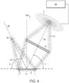
- Figure 4 is a schematic view of a further embodiment of an illumination system 100.
- the beam splitter 4 is omitted.
- the configurable area light source 2 is arranged such that the optical axis 20 of the illumination beam path 21 is tilted at an angle ⁇ with respect to surface 5 of the object 6.
- the light from the area light source 2 is imaged by the illumination lens 12 onto the surface 5 of the object 6.
- the light reflected from the surface 5 of the object 6 propagates along the imaging optical axis 80 of the illumination beam path 81.
- the field of view 13 on the surface 5 of the object 6 is imaged onto the imaging lens pupil (aperture) 83 (imaging lens and camera not shown).
- the imaging optical axis 80 of the imaging beam path 81 is tilted at an angle ⁇ with respect to the surface 5 of the object 6.
- the optical setup of the illumination system 100 is such that the value of an angle ⁇ of the optical axis 20 of the illumination beam path 21 equals the value of an angle ⁇ of the imaging optical axis 80 of the imaging beam path 81.
- the bright field illumination is achieved without the use of the beam splitter. In other words: an inspection tool where the value of the illumination angle ⁇ equals the value of the imaging angle ⁇ .
- Figure 5 is a schematic view of the value degree of the collimation beam opening angle 84 without the use of an illumination lens 12. Instead of the illumination lens 12 a diffuser plate 11 of an area light source (nor shown here) is positioned prior to the beam splitter 4. As a result from the illumination of the object 6 with a wide beam and without an illumination lens 12 one obtains an asymmetric wide beam which is a traditional wide coaxial illumination. Because of the wide beam opening angle 22 (see Figure 3 ) the imaging quality of the object 6 in the camera 8 will not be sensitive to a tilt of surface 5 of object.
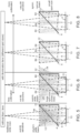
- Figure 6 to Figure 8 show the dependence of the collimation beam opening angle 84 from the spot size (area diameter) of the illumination light.
- Figure 6 is a schematic view of the degree of collimation beam opening angle 84 using a configurable area light source 2 with a huge spot size (huge area diameter) and an illumination lens 12. Due to the huge spot size (huge area diameter) set by the configurable area light source a portion 24 of the collimation beam opening angle 84 is cut off. This makes the beam opening angle 84 asymmetrical towards the edges of the field of view 13. The light, reflected from the surface 5 of the object 6, is not sensitive to a tilt of the beam splitter 4.
- Figure 7 is a schematic view of the degree of collimation beam opening angle 84 using a configurable area light source with an intermediate spot size (reduced spot size compared to figure 6 ). From the illumination lens 12 the light from the configurable area light source is collimated via the beam splitter 4 onto the surface 5 of the object 6. From figure 7 it is clear that with the reduced spot size the collimation beam opening angle 84 becomes narrower. Additionally, the light reflected from the surface 5 of the object 6 is now sensitive to a tilt of the surface 5 object 6.
- Figure 8 is a schematic view of the degree of collimation beam opening angle 84. Compared with the schematic view of figure 7 the spot size is reduced further. The configurable area light source 2 has now a small spot size (small area diameter).
- the result of the narrow beam opening angle is that the set-up of the illumination system is very sensitive to the tilt of the surface 5 of the object 6. Additionally, the light reflected from the surface 5 of the object 6 becomes more collimated compared with the spot sizes (area diameters) shown in figure 6 or 7 .
- FIG 9 is a top view of an embodiment of a configurable area light source 2 not forming part of the claimed invention.
- the area light source 2 is configured by a plurality of light emitting elements 14, which are arranged in a 2-dimensional manner on a carrier 16.
- the light emitting elements 14 are arranged in rows 17 1 , 17 2 ,...,17 N and columns 18 1 , 18 2 ,...,18 N and thereby form a matrix.
- the light emitting elements 14 are light emitting diodes (LEDs).
- the configurable area light source 2 is assigned to a control and drive device 30, or any embedded system which can address the area light source 2 accordingly.
- Figure 9 shows one embodiment not forming part of the claimed invention how the different sizes 19 1 , 19 2 ,...,19 N of the configurable area light source 2 are initialized.
- the light emitting elements 14 are addressed by the control and drive device 30 such that various sizes of the circles of the area light source 2 are addressed. It has to be noted that the addressable form of circles of the configurable area light source 2 should not be considered as a limiting factor.
- Figure 10 is a side view of the embodiment of the configurable area light source 2 of figure 9 which does not form part of the claimed invention.
- the light emitting elements 14 are arranged on the carrier 16.
- the configurable area light source 2 in addition can be provided with a diffuser (not shown) in order to achieve a uniform light distribution (area) of the addressed light emitting elements 14 on the carrier 16.
- the configurable area light source 2 is an area made of concentric geometrical shapes 23.
- the ideal solution would be to use concentric circles 25.
- This embodiment which does not form part of the claimed invention is shown in Figure 11 , wherein the configurable area light source 2 is formed by the light emitting elements 14 already positioned in the shape of the concentric circles 25.
- Figure 12 shows another embodiment of a configurable area light source 2 which does not form part of the claimed invention.
- the easiest solution for the positioning of the light emitting elements 14 would be to use concentric rectangles 26.
- the geometrical shapes 23 are rectangles, which have the drawback that the collimation angles are different for the diagonal direction versus the horizontal/vertical direction of the rectangles.
- Figure 13 shows an embodiment of the present invention of a configurable area light source 2.
- a good compromise compared with the embodiment shown in figure 12 , is to use concentric hexagons 27 as the concentric shapes 23. This may be achieved for example by making a staggered grid of light emitting elements 14 (not shown here).
- the design of the area light source is not limited to concentric geometrical shapes 23 shown in figures 11 to 13 .
- any pattern can be projected by addressing the light emitting elements 14 of the area light source 2. This will result in light beams having the desired pattern and the desired light beam opening angle.
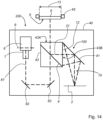
- Figure 14 shows a possible embodiment of the integration of the inventive illumination system 100 into an inspection apparatus 200.
- the inventive illumination system 100 is integrated in an existing housing 40 of the inspection apparatus 200.
- the inventive illumination system 100 provides different light beam opening angles in one coaxial illumination setup.
- the light 10 from the configurable area light source 2 is directed via a mirror 41 to the illumination lens 12 (one possible embodiment of the illumination lens 12 is a Fresnel lens).
- the mirror 41 is necessary for folding illumination beam path 21. This saves space and enables the integration of the illumination system 100 into the inspection apparatus 200.
- the beam splitter 4 of the inventive illumination system 100 is mounted in a holder 43.
- the object 6, to be inspected is held by a carrier 45 so that the surface 5 of the object 6 faces a first side face 43A of the holder 43.
- the mirror 41 is mounted to a second side face 43B of the holder 43 such that illumination light 10 from the configurable area light source 2 is directed via the illumination lens 12 onto the beam splitter 4 and from there onto the surface 5 of the object 6.
- the light reflected from the surface 5 of the object 6 travels along the imaging beam path 81 to the camera 8.
- the imaging lens 7 images a field of view 13 of the surface 5 of the object 6 into the image plane 9 of the camera 8.
- two additional mirrors 82 are provided in the imaging beam path 81, in order to fold the imaging beam path 81 for space reasons.
- FIG 15 shows an additional embodiment which does not form part of the claimed invention of a configurable area light source 2.
- a LCD-screen 50 is positioned after at least one light emitting element 14.
- a single light emitting element 14 is used which provides a homogeneous area lightning of the back of the LCD 50 (see the side view configurable area light source 2 as shown in Figure 16 ).
- the plurality of pixels 51 of the LCD 50 can be addressed individually.
- the LCD 50 comprises a plurality of pixels 51, arranged in a 2-dimensional manner. Accordingly, various illumination patterns can be formed by addressing the pixels 51 individually by a known control device (not shown).
- the pixels 51 of the configurable area light source 2 are addressed in a manner , so that a group of pixels block the light 55 from the light emitting element 14 completely and the other pixels 51 let the light 55 from the light emitting element 14 pass (see figure 16 ). It is evident for a skilled person that the transmittance of the individual pixels 51can be adjusted as well.
Landscapes
- Physics & Mathematics (AREA)
- General Physics & Mathematics (AREA)
- Analytical Chemistry (AREA)
- Chemical & Material Sciences (AREA)
- Health & Medical Sciences (AREA)
- Life Sciences & Earth Sciences (AREA)
- Biochemistry (AREA)
- General Health & Medical Sciences (AREA)
- Immunology (AREA)
- Pathology (AREA)
- Optics & Photonics (AREA)
- Engineering & Computer Science (AREA)
- Computer Vision & Pattern Recognition (AREA)
- Signal Processing (AREA)
- Investigating Materials By The Use Of Optical Means Adapted For Particular Applications (AREA)
- Length Measuring Devices By Optical Means (AREA)
Claims (4)
- Verfahren zum Prüfen eines Objekts (6), umfassend:a. Lenken von Beleuchtungslicht, wobei das Beleuchtungslicht einen Lichtstrahlöffnungswinkel definiert, von einer konfigurierbaren Flächenlichtquelle (2) auf einen Strahlenteiler (4) über eine Beleuchtungslinse (12) entlang eines Beleuchtungsstrahlengangs (21) auf eine Oberfläche (5) eines Objekts (6);b. Lenken des von der Oberfläche (5) des Objekts (6) reflektierten Lichts entlang eines Abbildungsstrahlengangs (81) ;c. Abbilden des von der Oberfläche (5) des Objekts (6) reflektierten Lichts mit einer Abbildungslinse (7) auf eine Bildebene (9) einer Kamera (8);d. Ändern des Durchmessers des Beleuchtungslichts und dadurch Ändern des Öffnungswinkels des Lichtstrahls;e. Wiederholen der Schritte a-d; undErzeugen eines Sichtfelds auf der Oberfläche (5) des Objekts (6) in Echtzeitbildern mit unterschiedlichen Strahlöffnungswinkeln bzw. Kollimationswinkeln, wobei die konfigurierbare Flächenlichtquelle (2) eine 2-dimensionale Anordnung einer Vielzahl von lichtemittierenden Elementen (14) ist; wobei die Vielzahl von lichtemittierenden Elementen (14) eine Vielzahl von Leuchtdioden beinhaltet; wobei die 2-dimensionale Anordnung der Vielzahl von lichtemittierenden Elementen (14) durch eine Anordnung der Vielzahl von lichtemittierenden Elementen (14) in einer Vielzahl von konzentrischen geometrischen Formen (23) definiert ist; wobei der konfigurierbaren Flächenlichtquelle (2) eine Steuer- und Antriebsvorrichtung (30) zugeordnet ist, sodass die Vielzahl von konzentrischen und adressierbaren geometrischen Formen erzeugt wird, um unterschiedliche Strahldurchmesser zu erlangen, wobei die Vielzahl von konzentrischen geometrischen Formen (23) eine Vielzahl von konzentrischen Sechsecken (27) beinhaltet.
- Prüfwerkzeug (200), das dazu konfiguriert ist, das Verfahren nach Anspruch 1 zu umzusetzen, umfassend:eine Kamera (8), die in einer optischen Abbildungsachse (80) eines Abbildungsstrahlengangs (81) angeordnet ist;eine Abbildungslinse (83), die im Abbildungsstrahlengang (81) angeordnet ist, um mindestens einen Abschnitt einer Oberfläche (5) eines Objekts (6) in einer Bildebene (9) der Kamera (8) abzubilden;ein Beleuchtungssystem (100) mit einer konfigurierbaren Flächenlichtquelle (2), wobei die konfigurierbare Flächenlichtquelle (2) in einer Beleuchtungsoptikachse (20) eines Beleuchtungsstrahlengangs (21) angeordnet ist und die konfigurierbare Flächenlichtquelle (2) so konfiguriert ist, dass unterschiedliche Strahldurchmesser einstellbar sind;mindestens eine Beleuchtungslinse (12), die im Beleuchtungsstrahlengang (21) angeordnet ist, um einen kollimierten Strahl auf ein Sichtfeld auf der Oberfläche (5) des Objekts (6) zu lenken, wobei ein Wert eines Einfallswinkels der optischen Beleuchtungsachse (20) des Beleuchtungsstrahlengangs (21) gleich einem Wert eines Reflexionswinkels einer optischen Abbildungsachse des Abbildungsstrahlengangs ist;einen Strahlteiler (4), der im Beleuchtungspfad nach der mindestens einen Beleuchtungslinse (12) angeordnet ist, wobei der Strahlteiler (4) kollimiertes Beleuchtungslicht von der konfigurierbaren Flächenlichtquelle (2) entlang einer umgelenkten optischen Beleuchtungsachse des Beleuchtungsstrahlengangs auf die Oberfläche (5) des Objekts (6) lenkt und wobei die optische Abbildungsachse des Abbildungsstrahlengangs koaxial mit der umgelenkten optischen Beleuchtungsachse des Beleuchtungsstrahlengangs ist; undwobei die einstellbaren unterschiedlichen Strahldurchmesser eine Variation eines kollimierten Strahlöffnungswinkels (22) ermöglichen;wobei die konfigurierbare Flächenlichtquelle (2) eine 2-dimensionale Anordnung einer Vielzahl von lichtemittierenden Elementen (14) ist; wobei die Vielzahl von lichtemittierenden Elementen (14) eine Vielzahl von lichtemittierenden Dioden beinhaltet; wobei die 2-dimensionale Anordnung der Vielzahl von lichtemittierenden Elementen (14) durch eine Anordnung der Vielzahl von lichtemittierenden Elementen (14) in einer Vielzahl von konzentrischen geometrischen Formen (23) definiert ist;eine Steuer- und Antriebsvorrichtung (30), die der konfigurierbaren Flächenlichtquelle (2) zugeordnet ist, sodass eine Vielzahl konzentrischer geometrischer Formen (23) der Beleuchtung erzeugt wird, um unterschiedliche Strahldurchmesser zu erlangen, wobei die Vielzahl konzentrischer geometrischer Formen (23) eine Vielzahl konzentrischer Sechsecke (27) beinhaltet.
- Prüfwerkzeug nach Anspruch 2, wobei der Abbildungsstrahlengang (81) mindestens einmal gefaltet wird, um Licht von dem Sichtfeld auf der Oberfläche (5) des Objekts auf die Bildebene (9) der Kamera (8) zu lenken; oder
wobei der Beleuchtungsstrahlengang (81) mindestens einmal gefaltet wird, um Licht von der konfigurierbaren Flächenlichtquelle (2) auf die Oberfläche (5) des Objekts (6) zu lenken. - Prüfwerkzeug nach einem der vorhergehenden Ansprüche, wobei das Objekt (6) ein Spiegel ist, der Abbildungsstrahlengang (81) genau auf die Linsenpupille der Abbildungslinse (83) gelenkt wird.
Applications Claiming Priority (2)
| Application Number | Priority Date | Filing Date | Title |
|---|---|---|---|
| US201462073393P | 2014-10-31 | 2014-10-31 | |
| PCT/US2015/058486 WO2016070133A1 (en) | 2014-10-31 | 2015-10-30 | Illumination system, inspection tool with illumination system, and method of operating an illumination system |
Publications (3)
| Publication Number | Publication Date |
|---|---|
| EP3140638A1 EP3140638A1 (de) | 2017-03-15 |
| EP3140638A4 EP3140638A4 (de) | 2018-01-24 |
| EP3140638B1 true EP3140638B1 (de) | 2024-02-14 |
Family
ID=55858432
Family Applications (1)
| Application Number | Title | Priority Date | Filing Date |
|---|---|---|---|
| EP15853870.2A Active EP3140638B1 (de) | 2014-10-31 | 2015-10-30 | Beleuchtungssystem, prüfwerkzeug mit beleuchtungssystem und verfahren zum betrieb eines beleuchtungssystems |
Country Status (9)
| Country | Link |
|---|---|
| EP (1) | EP3140638B1 (de) |
| JP (2) | JP2017533437A (de) |
| KR (1) | KR102272438B1 (de) |
| CN (2) | CN106796181A (de) |
| MY (1) | MY188346A (de) |
| PH (1) | PH12017500736A1 (de) |
| SG (1) | SG11201702728UA (de) |
| TW (1) | TWI697662B (de) |
| WO (1) | WO2016070133A1 (de) |
Families Citing this family (5)
| Publication number | Priority date | Publication date | Assignee | Title |
|---|---|---|---|---|
| KR101795322B1 (ko) | 2016-12-30 | 2017-11-08 | 허철 | 유기발광다이오드 검사용 듀얼 이미징 텔레센트릭 광학장치 |
| JP2021527842A (ja) * | 2018-06-04 | 2021-10-14 | イェノプティック オプティカル システムズ ゲーエムベーハー | 顕微鏡像を捕捉する顕微鏡及び方法並びに平面リフレクタの使用 |
| WO2020148749A1 (en) * | 2019-01-14 | 2020-07-23 | Orbotech Ltd. | Multiplexed image acquisition device for optical system |
| US10816464B2 (en) * | 2019-01-23 | 2020-10-27 | Applied Materials, Inc. | Imaging reflectometer |
| JP7392582B2 (ja) * | 2020-06-12 | 2023-12-06 | オムロン株式会社 | 検査システムおよび検査方法 |
Family Cites Families (19)
| Publication number | Priority date | Publication date | Assignee | Title |
|---|---|---|---|---|
| GB9325932D0 (en) * | 1993-12-18 | 1994-02-23 | Ibm | Faceplate bonding process for a visual display unit |
| US5949584A (en) * | 1997-05-13 | 1999-09-07 | Northeast Robotics Llc | Wafer |
| JP3472750B2 (ja) * | 2000-04-10 | 2003-12-02 | シーシーエス株式会社 | 表面検査装置 |
| US20040223342A1 (en) * | 2001-12-31 | 2004-11-11 | Klipstein Donald L. | LED inspection lamp, cluster LED, and LED with stabilizing agents |
| US20040042001A1 (en) * | 2002-04-18 | 2004-03-04 | Kla-Tencor Technologies Corporation | Simultaneous multi-spot inspection and imaging |
| US6870949B2 (en) * | 2003-02-26 | 2005-03-22 | Electro Scientific Industries | Coaxial narrow angle dark field lighting |
| US7352467B2 (en) * | 2003-10-24 | 2008-04-01 | University Of Washington | Surface plasmon resonance imaging system and method |
| CN100433245C (zh) * | 2004-03-11 | 2008-11-12 | 株式会社液晶先端技术开发中心 | 激光结晶设备及激光结晶方法 |
| JP2006011371A (ja) * | 2004-05-26 | 2006-01-12 | Fuji Photo Film Co Ltd | パターン形成方法 |
| US7738092B1 (en) * | 2008-01-08 | 2010-06-15 | Kla-Tencor Corporation | System and method for reducing speckle noise in die-to-die inspection systems |
| US7990531B2 (en) * | 2008-06-05 | 2011-08-02 | Coopervision International Holding Company, Lp | Multi-imaging automated inspection methods and systems for wet ophthalmic lenses |
| US8502968B2 (en) * | 2008-09-12 | 2013-08-06 | Ceramicam Ltd. | Surface scanning device |
| JP2012083211A (ja) * | 2010-10-12 | 2012-04-26 | Canon Inc | 表面状態検査装置、表面状態検査方法及びプログラム |
| JP5027946B1 (ja) * | 2011-12-28 | 2012-09-19 | 新明和工業株式会社 | 検査システム |
| JP2013145123A (ja) * | 2012-01-13 | 2013-07-25 | Seiwa Optical Co Ltd | 広角反射同軸照明付光学系 |
| US9395066B2 (en) * | 2012-01-13 | 2016-07-19 | Laser Devices, Inc. | Adjustable beam illuminator |
| US9128064B2 (en) * | 2012-05-29 | 2015-09-08 | Kla-Tencor Corporation | Super resolution inspection system |
| JP6205780B2 (ja) * | 2013-03-27 | 2017-10-04 | 凸版印刷株式会社 | 照明装置及び検査装置 |
| US9255887B2 (en) * | 2013-06-19 | 2016-02-09 | Kla-Tencor Corporation | 2D programmable aperture mechanism |
-
2015
- 2015-10-30 EP EP15853870.2A patent/EP3140638B1/de active Active
- 2015-10-30 WO PCT/US2015/058486 patent/WO2016070133A1/en active Application Filing
- 2015-10-30 JP JP2017523513A patent/JP2017533437A/ja active Pending
- 2015-10-30 TW TW104135916A patent/TWI697662B/zh active
- 2015-10-30 CN CN201580055825.6A patent/CN106796181A/zh active Pending
- 2015-10-30 KR KR1020177014639A patent/KR102272438B1/ko active IP Right Grant
- 2015-10-30 MY MYPI2016002118A patent/MY188346A/en unknown
- 2015-10-30 SG SG11201702728UA patent/SG11201702728UA/en unknown
- 2015-10-30 CN CN202210561988.3A patent/CN114813758A/zh active Pending
-
2017
- 2017-04-20 PH PH12017500736A patent/PH12017500736A1/en unknown
-
2021
- 2021-03-30 JP JP2021057066A patent/JP7193571B2/ja active Active
Also Published As
| Publication number | Publication date |
|---|---|
| JP7193571B2 (ja) | 2022-12-20 |
| WO2016070133A1 (en) | 2016-05-06 |
| TW201627656A (zh) | 2016-08-01 |
| EP3140638A1 (de) | 2017-03-15 |
| MY188346A (en) | 2021-12-01 |
| JP2017533437A (ja) | 2017-11-09 |
| PH12017500736A1 (en) | 2017-10-09 |
| JP2021101194A (ja) | 2021-07-08 |
| EP3140638A4 (de) | 2018-01-24 |
| TWI697662B (zh) | 2020-07-01 |
| KR102272438B1 (ko) | 2021-07-02 |
| SG11201702728UA (en) | 2017-05-30 |
| CN106796181A (zh) | 2017-05-31 |
| KR20170080631A (ko) | 2017-07-10 |
| CN114813758A (zh) | 2022-07-29 |
Similar Documents
| Publication | Publication Date | Title |
|---|---|---|
| US10379057B2 (en) | Illumination system, inspection tool with illumination system, and method of operating an illumination system | |
| JP7193571B2 (ja) | 照明システム、照明システムを有する検査ツール、および照明システムを作動させる方法 | |
| EP1581781B1 (de) | Verfahren und vorrichtung zur gleichzeitigen 2d- und topographischen untersuchung | |
| US8928892B2 (en) | Wavefront analysis inspection apparatus and method | |
| US11531193B2 (en) | Optical arrangement, multi-spot scanning microscope and method for operating a microscope | |
| TWI557434B (zh) | 照明系統 | |
| KR102373287B1 (ko) | 이음새없이 형성된 텔레센트릭 명시야 및 환형 암시야 조명 | |
| KR102226444B1 (ko) | 적응적 확산 조명 시스템들 및 방법들 | |
| US20180156414A1 (en) | Vehicle lighting apparatus | |
| JP2016024195A5 (de) | ||
| JP2017533437A5 (de) | ||
| TWI393873B (zh) | 控制光束角作用區的裝置及方法 | |
| US20180080880A1 (en) | Optical scattering measurement method and apparatus using micro lens matrix | |
| JP6513980B2 (ja) | 撮像装置及び撮像方法 | |
| JP2021085815A (ja) | 光照射装置、検査システム、及び、光照射方法 | |
| JP2013083726A (ja) | 拡大観察装置 | |
| JP2024065760A (ja) | ライン光照射装置及び検査システム | |
| JP2008046247A (ja) | 顕微鏡装置 | |
| JP2018066848A (ja) | シート照明顕微鏡 |
Legal Events
| Date | Code | Title | Description |
|---|---|---|---|
| STAA | Information on the status of an ep patent application or granted ep patent |
Free format text: STATUS: THE INTERNATIONAL PUBLICATION HAS BEEN MADE |
|
| PUAI | Public reference made under article 153(3) epc to a published international application that has entered the european phase |
Free format text: ORIGINAL CODE: 0009012 |
|
| STAA | Information on the status of an ep patent application or granted ep patent |
Free format text: STATUS: REQUEST FOR EXAMINATION WAS MADE |
|
| 17P | Request for examination filed |
Effective date: 20161208 |
|
| AK | Designated contracting states |
Kind code of ref document: A1 Designated state(s): AL AT BE BG CH CY CZ DE DK EE ES FI FR GB GR HR HU IE IS IT LI LT LU LV MC MK MT NL NO PL PT RO RS SE SI SK SM TR |
|
| AX | Request for extension of the european patent |
Extension state: BA ME |
|
| A4 | Supplementary search report drawn up and despatched |
Effective date: 20171221 |
|
| RIC1 | Information provided on ipc code assigned before grant |
Ipc: G02B 26/00 20060101ALI20171215BHEP Ipc: G01N 21/84 20060101AFI20171215BHEP |
|
| DAV | Request for validation of the european patent (deleted) | ||
| DAX | Request for extension of the european patent (deleted) | ||
| STAA | Information on the status of an ep patent application or granted ep patent |
Free format text: STATUS: EXAMINATION IS IN PROGRESS |
|
| 17Q | First examination report despatched |
Effective date: 20180913 |
|
| STAA | Information on the status of an ep patent application or granted ep patent |
Free format text: STATUS: EXAMINATION IS IN PROGRESS |
|
| STAA | Information on the status of an ep patent application or granted ep patent |
Free format text: STATUS: EXAMINATION IS IN PROGRESS |
|
| P01 | Opt-out of the competence of the unified patent court (upc) registered |
Effective date: 20230526 |
|
| GRAP | Despatch of communication of intention to grant a patent |
Free format text: ORIGINAL CODE: EPIDOSNIGR1 |
|
| STAA | Information on the status of an ep patent application or granted ep patent |
Free format text: STATUS: GRANT OF PATENT IS INTENDED |
|
| INTG | Intention to grant announced |
Effective date: 20230913 |
|
| GRAS | Grant fee paid |
Free format text: ORIGINAL CODE: EPIDOSNIGR3 |
|
| GRAA | (expected) grant |
Free format text: ORIGINAL CODE: 0009210 |
|
| STAA | Information on the status of an ep patent application or granted ep patent |
Free format text: STATUS: THE PATENT HAS BEEN GRANTED |
|
| AK | Designated contracting states |
Kind code of ref document: B1 Designated state(s): AL AT BE BG CH CY CZ DE DK EE ES FI FR GB GR HR HU IE IS IT LI LT LU LV MC MK MT NL NO PL PT RO RS SE SI SK SM TR |
|
| REG | Reference to a national code |
Ref country code: GB Ref legal event code: FG4D |
|
| RIN1 | Information on inventor provided before grant (corrected) |
Inventor name: GOORMAN, KOEN Inventor name: BEGOC, PAULINE Inventor name: DE GREEVE, JOHAN Inventor name: CAUWENBERGHS, FILIP |
|
| REG | Reference to a national code |
Ref country code: CH Ref legal event code: EP |
|
| REG | Reference to a national code |
Ref country code: DE Ref legal event code: R096 Ref document number: 602015087564 Country of ref document: DE |
|
| REG | Reference to a national code |
Ref country code: IE Ref legal event code: FG4D |
|
| REG | Reference to a national code |
Ref country code: NL Ref legal event code: FP |
|
| REG | Reference to a national code |
Ref country code: LT Ref legal event code: MG9D |
|
| PG25 | Lapsed in a contracting state [announced via postgrant information from national office to epo] |
Ref country code: IS Free format text: LAPSE BECAUSE OF FAILURE TO SUBMIT A TRANSLATION OF THE DESCRIPTION OR TO PAY THE FEE WITHIN THE PRESCRIBED TIME-LIMIT Effective date: 20240614 |
|
| PG25 | Lapsed in a contracting state [announced via postgrant information from national office to epo] |
Ref country code: LT Free format text: LAPSE BECAUSE OF FAILURE TO SUBMIT A TRANSLATION OF THE DESCRIPTION OR TO PAY THE FEE WITHIN THE PRESCRIBED TIME-LIMIT Effective date: 20240214 |
|
| PG25 | Lapsed in a contracting state [announced via postgrant information from national office to epo] |
Ref country code: GR Free format text: LAPSE BECAUSE OF FAILURE TO SUBMIT A TRANSLATION OF THE DESCRIPTION OR TO PAY THE FEE WITHIN THE PRESCRIBED TIME-LIMIT Effective date: 20240515 |
|
| REG | Reference to a national code |
Ref country code: AT Ref legal event code: MK05 Ref document number: 1657415 Country of ref document: AT Kind code of ref document: T Effective date: 20240214 |
|
| PG25 | Lapsed in a contracting state [announced via postgrant information from national office to epo] |
Ref country code: RS Free format text: LAPSE BECAUSE OF FAILURE TO SUBMIT A TRANSLATION OF THE DESCRIPTION OR TO PAY THE FEE WITHIN THE PRESCRIBED TIME-LIMIT Effective date: 20240514 Ref country code: HR Free format text: LAPSE BECAUSE OF FAILURE TO SUBMIT A TRANSLATION OF THE DESCRIPTION OR TO PAY THE FEE WITHIN THE PRESCRIBED TIME-LIMIT Effective date: 20240214 |
|
| PG25 | Lapsed in a contracting state [announced via postgrant information from national office to epo] |
Ref country code: ES Free format text: LAPSE BECAUSE OF FAILURE TO SUBMIT A TRANSLATION OF THE DESCRIPTION OR TO PAY THE FEE WITHIN THE PRESCRIBED TIME-LIMIT Effective date: 20240214 |
|
| PG25 | Lapsed in a contracting state [announced via postgrant information from national office to epo] |
Ref country code: AT Free format text: LAPSE BECAUSE OF FAILURE TO SUBMIT A TRANSLATION OF THE DESCRIPTION OR TO PAY THE FEE WITHIN THE PRESCRIBED TIME-LIMIT Effective date: 20240214 |
|
| PG25 | Lapsed in a contracting state [announced via postgrant information from national office to epo] |
Ref country code: RS Free format text: LAPSE BECAUSE OF FAILURE TO SUBMIT A TRANSLATION OF THE DESCRIPTION OR TO PAY THE FEE WITHIN THE PRESCRIBED TIME-LIMIT Effective date: 20240514 Ref country code: NO Free format text: LAPSE BECAUSE OF FAILURE TO SUBMIT A TRANSLATION OF THE DESCRIPTION OR TO PAY THE FEE WITHIN THE PRESCRIBED TIME-LIMIT Effective date: 20240514 Ref country code: LT Free format text: LAPSE BECAUSE OF FAILURE TO SUBMIT A TRANSLATION OF THE DESCRIPTION OR TO PAY THE FEE WITHIN THE PRESCRIBED TIME-LIMIT Effective date: 20240214 Ref country code: IS Free format text: LAPSE BECAUSE OF FAILURE TO SUBMIT A TRANSLATION OF THE DESCRIPTION OR TO PAY THE FEE WITHIN THE PRESCRIBED TIME-LIMIT Effective date: 20240614 Ref country code: HR Free format text: LAPSE BECAUSE OF FAILURE TO SUBMIT A TRANSLATION OF THE DESCRIPTION OR TO PAY THE FEE WITHIN THE PRESCRIBED TIME-LIMIT Effective date: 20240214 Ref country code: GR Free format text: LAPSE BECAUSE OF FAILURE TO SUBMIT A TRANSLATION OF THE DESCRIPTION OR TO PAY THE FEE WITHIN THE PRESCRIBED TIME-LIMIT Effective date: 20240515 Ref country code: FI Free format text: LAPSE BECAUSE OF FAILURE TO SUBMIT A TRANSLATION OF THE DESCRIPTION OR TO PAY THE FEE WITHIN THE PRESCRIBED TIME-LIMIT Effective date: 20240214 Ref country code: ES Free format text: LAPSE BECAUSE OF FAILURE TO SUBMIT A TRANSLATION OF THE DESCRIPTION OR TO PAY THE FEE WITHIN THE PRESCRIBED TIME-LIMIT Effective date: 20240214 Ref country code: BG Free format text: LAPSE BECAUSE OF FAILURE TO SUBMIT A TRANSLATION OF THE DESCRIPTION OR TO PAY THE FEE WITHIN THE PRESCRIBED TIME-LIMIT Effective date: 20240214 Ref country code: AT Free format text: LAPSE BECAUSE OF FAILURE TO SUBMIT A TRANSLATION OF THE DESCRIPTION OR TO PAY THE FEE WITHIN THE PRESCRIBED TIME-LIMIT Effective date: 20240214 |
|
| PG25 | Lapsed in a contracting state [announced via postgrant information from national office to epo] |
Ref country code: PT Free format text: LAPSE BECAUSE OF FAILURE TO SUBMIT A TRANSLATION OF THE DESCRIPTION OR TO PAY THE FEE WITHIN THE PRESCRIBED TIME-LIMIT Effective date: 20240614 Ref country code: PL Free format text: LAPSE BECAUSE OF FAILURE TO SUBMIT A TRANSLATION OF THE DESCRIPTION OR TO PAY THE FEE WITHIN THE PRESCRIBED TIME-LIMIT Effective date: 20240214 |
|
| PG25 | Lapsed in a contracting state [announced via postgrant information from national office to epo] |
Ref country code: SE Free format text: LAPSE BECAUSE OF FAILURE TO SUBMIT A TRANSLATION OF THE DESCRIPTION OR TO PAY THE FEE WITHIN THE PRESCRIBED TIME-LIMIT Effective date: 20240214 Ref country code: PT Free format text: LAPSE BECAUSE OF FAILURE TO SUBMIT A TRANSLATION OF THE DESCRIPTION OR TO PAY THE FEE WITHIN THE PRESCRIBED TIME-LIMIT Effective date: 20240614 Ref country code: PL Free format text: LAPSE BECAUSE OF FAILURE TO SUBMIT A TRANSLATION OF THE DESCRIPTION OR TO PAY THE FEE WITHIN THE PRESCRIBED TIME-LIMIT Effective date: 20240214 Ref country code: LV Free format text: LAPSE BECAUSE OF FAILURE TO SUBMIT A TRANSLATION OF THE DESCRIPTION OR TO PAY THE FEE WITHIN THE PRESCRIBED TIME-LIMIT Effective date: 20240214 |