EP3140628B9 - Système et procédé d'analyse d'un faisceau lumineux guidé par une optique de guidage de faisceau - Google Patents
Système et procédé d'analyse d'un faisceau lumineux guidé par une optique de guidage de faisceau Download PDFInfo
- Publication number
- EP3140628B9 EP3140628B9 EP15724539.0A EP15724539A EP3140628B9 EP 3140628 B9 EP3140628 B9 EP 3140628B9 EP 15724539 A EP15724539 A EP 15724539A EP 3140628 B9 EP3140628 B9 EP 3140628B9
- Authority
- EP
- European Patent Office
- Prior art keywords
- neutral density
- density filter
- graduated neutral
- graduated
- arrangement
- Prior art date
- Legal status (The legal status is an assumption and is not a legal conclusion. Google has not performed a legal analysis and makes no representation as to the accuracy of the status listed.)
- Active
Links
- 230000003287 optical effect Effects 0.000 title claims description 21
- 238000000034 method Methods 0.000 title claims description 7
- 230000005540 biological transmission Effects 0.000 claims description 78
- 238000010606 normalization Methods 0.000 claims description 8
- 238000011144 upstream manufacturing Methods 0.000 claims description 4
- 230000007935 neutral effect Effects 0.000 claims 32
- 238000004458 analytical method Methods 0.000 description 21
- 230000005855 radiation Effects 0.000 description 18
- 238000005259 measurement Methods 0.000 description 16
- 238000013461 design Methods 0.000 description 11
- 230000000694 effects Effects 0.000 description 6
- 239000011159 matrix material Substances 0.000 description 6
- 230000003071 parasitic effect Effects 0.000 description 6
- 230000005484 gravity Effects 0.000 description 5
- 238000003384 imaging method Methods 0.000 description 5
- 238000006073 displacement reaction Methods 0.000 description 4
- 238000005516 engineering process Methods 0.000 description 4
- 230000010354 integration Effects 0.000 description 4
- 210000001747 pupil Anatomy 0.000 description 4
- 230000035945 sensitivity Effects 0.000 description 4
- ATJFFYVFTNAWJD-UHFFFAOYSA-N Tin Chemical compound [Sn] ATJFFYVFTNAWJD-UHFFFAOYSA-N 0.000 description 3
- 238000013459 approach Methods 0.000 description 3
- 230000008859 change Effects 0.000 description 3
- 230000005670 electromagnetic radiation Effects 0.000 description 3
- 238000012546 transfer Methods 0.000 description 3
- 239000006096 absorbing agent Substances 0.000 description 2
- 230000015572 biosynthetic process Effects 0.000 description 2
- 238000001514 detection method Methods 0.000 description 2
- 230000005577 local transmission Effects 0.000 description 2
- 239000000463 material Substances 0.000 description 2
- 230000002441 reversible effect Effects 0.000 description 2
- 239000013077 target material Substances 0.000 description 2
- 230000009466 transformation Effects 0.000 description 2
- PCTMTFRHKVHKIS-BMFZQQSSSA-N (1s,3r,4e,6e,8e,10e,12e,14e,16e,18s,19r,20r,21s,25r,27r,30r,31r,33s,35r,37s,38r)-3-[(2r,3s,4s,5s,6r)-4-amino-3,5-dihydroxy-6-methyloxan-2-yl]oxy-19,25,27,30,31,33,35,37-octahydroxy-18,20,21-trimethyl-23-oxo-22,39-dioxabicyclo[33.3.1]nonatriaconta-4,6,8,10 Chemical compound C1C=C2C[C@@H](OS(O)(=O)=O)CC[C@]2(C)[C@@H]2[C@@H]1[C@@H]1CC[C@H]([C@H](C)CCCC(C)C)[C@@]1(C)CC2.O[C@H]1[C@@H](N)[C@H](O)[C@@H](C)O[C@H]1O[C@H]1/C=C/C=C/C=C/C=C/C=C/C=C/C=C/[C@H](C)[C@@H](O)[C@@H](C)[C@H](C)OC(=O)C[C@H](O)C[C@H](O)CC[C@@H](O)[C@H](O)C[C@H](O)C[C@](O)(C[C@H](O)[C@H]2C(O)=O)O[C@H]2C1 PCTMTFRHKVHKIS-BMFZQQSSSA-N 0.000 description 1
- 238000012935 Averaging Methods 0.000 description 1
- 229910000831 Steel Inorganic materials 0.000 description 1
- 230000002745 absorbent Effects 0.000 description 1
- 239000002250 absorbent Substances 0.000 description 1
- 230000004075 alteration Effects 0.000 description 1
- 238000012512 characterization method Methods 0.000 description 1
- 239000012141 concentrate Substances 0.000 description 1
- 230000008878 coupling Effects 0.000 description 1
- 238000010168 coupling process Methods 0.000 description 1
- 238000005859 coupling reaction Methods 0.000 description 1
- 230000005284 excitation Effects 0.000 description 1
- 238000009472 formulation Methods 0.000 description 1
- 230000007274 generation of a signal involved in cell-cell signaling Effects 0.000 description 1
- 235000019580 granularity Nutrition 0.000 description 1
- 238000002347 injection Methods 0.000 description 1
- 239000007924 injection Substances 0.000 description 1
- 238000009434 installation Methods 0.000 description 1
- 230000003993 interaction Effects 0.000 description 1
- 238000001459 lithography Methods 0.000 description 1
- MGIUUAHJVPPFEV-ABXDCCGRSA-N magainin ii Chemical compound C([C@H](NC(=O)[C@H](CCCCN)NC(=O)CNC(=O)[C@@H](NC(=O)CN)[C@@H](C)CC)C(=O)N[C@@H](CC(C)C)C(=O)N[C@@H](CC=1NC=NC=1)C(=O)N[C@@H](CO)C(=O)N[C@@H](C)C(=O)N[C@@H](CCCCN)C(=O)N[C@@H](CCCCN)C(=O)N[C@@H](CC=1C=CC=CC=1)C(=O)NCC(=O)N[C@@H](CCCCN)C(=O)N[C@@H](C)C(=O)N[C@@H](CC=1C=CC=CC=1)C(=O)N[C@@H](C(C)C)C(=O)NCC(=O)N[C@@H](CCC(O)=O)C(=O)N[C@@H]([C@@H](C)CC)C(=O)N[C@@H](CCSC)C(=O)N[C@@H](CC(N)=O)C(=O)N[C@@H](CO)C(O)=O)C1=CC=CC=C1 MGIUUAHJVPPFEV-ABXDCCGRSA-N 0.000 description 1
- 239000000203 mixture Substances 0.000 description 1
- 238000012634 optical imaging Methods 0.000 description 1
- 230000000737 periodic effect Effects 0.000 description 1
- 230000002093 peripheral effect Effects 0.000 description 1
- 238000007639 printing Methods 0.000 description 1
- 238000012545 processing Methods 0.000 description 1
- 230000010076 replication Effects 0.000 description 1
- 230000003362 replicative effect Effects 0.000 description 1
- 238000000926 separation method Methods 0.000 description 1
- 238000004088 simulation Methods 0.000 description 1
- 239000010959 steel Substances 0.000 description 1
- 239000000758 substrate Substances 0.000 description 1
- 230000002123 temporal effect Effects 0.000 description 1
- 238000009966 trimming Methods 0.000 description 1
- 239000013598 vector Substances 0.000 description 1
- 230000000007 visual effect Effects 0.000 description 1
Images


Classifications
-
- G—PHYSICS
- G01—MEASURING; TESTING
- G01J—MEASUREMENT OF INTENSITY, VELOCITY, SPECTRAL CONTENT, POLARISATION, PHASE OR PULSE CHARACTERISTICS OF INFRARED, VISIBLE OR ULTRAVIOLET LIGHT; COLORIMETRY; RADIATION PYROMETRY
- G01J1/00—Photometry, e.g. photographic exposure meter
- G01J1/42—Photometry, e.g. photographic exposure meter using electric radiation detectors
- G01J1/4257—Photometry, e.g. photographic exposure meter using electric radiation detectors applied to monitoring the characteristics of a beam, e.g. laser beam, headlamp beam
-
- G—PHYSICS
- G01—MEASURING; TESTING
- G01J—MEASUREMENT OF INTENSITY, VELOCITY, SPECTRAL CONTENT, POLARISATION, PHASE OR PULSE CHARACTERISTICS OF INFRARED, VISIBLE OR ULTRAVIOLET LIGHT; COLORIMETRY; RADIATION PYROMETRY
- G01J1/00—Photometry, e.g. photographic exposure meter
- G01J1/02—Details
- G01J1/04—Optical or mechanical part supplementary adjustable parts
- G01J1/0407—Optical elements not provided otherwise, e.g. manifolds, windows, holograms, gratings
- G01J1/0418—Optical elements not provided otherwise, e.g. manifolds, windows, holograms, gratings using attenuators
-
- G—PHYSICS
- G02—OPTICS
- G02B—OPTICAL ELEMENTS, SYSTEMS OR APPARATUS
- G02B5/00—Optical elements other than lenses
- G02B5/20—Filters
- G02B5/205—Neutral density filters
-
- H—ELECTRICITY
- H05—ELECTRIC TECHNIQUES NOT OTHERWISE PROVIDED FOR
- H05G—X-RAY TECHNIQUE
- H05G2/00—Apparatus or processes specially adapted for producing X-rays, not involving X-ray tubes, e.g. involving generation of a plasma
- H05G2/001—X-ray radiation generated from plasma
- H05G2/003—X-ray radiation generated from plasma being produced from a liquid or gas
- H05G2/005—X-ray radiation generated from plasma being produced from a liquid or gas containing a metal as principal radiation generating component
-
- H—ELECTRICITY
- H05—ELECTRIC TECHNIQUES NOT OTHERWISE PROVIDED FOR
- H05G—X-RAY TECHNIQUE
- H05G2/00—Apparatus or processes specially adapted for producing X-rays, not involving X-ray tubes, e.g. involving generation of a plasma
- H05G2/001—X-ray radiation generated from plasma
- H05G2/008—X-ray radiation generated from plasma involving a beam of energy, e.g. laser or electron beam in the process of exciting the plasma
-
- B—PERFORMING OPERATIONS; TRANSPORTING
- B23—MACHINE TOOLS; METAL-WORKING NOT OTHERWISE PROVIDED FOR
- B23K—SOLDERING OR UNSOLDERING; WELDING; CLADDING OR PLATING BY SOLDERING OR WELDING; CUTTING BY APPLYING HEAT LOCALLY, e.g. FLAME CUTTING; WORKING BY LASER BEAM
- B23K26/00—Working by laser beam, e.g. welding, cutting or boring
- B23K26/70—Auxiliary operations or equipment
- B23K26/702—Auxiliary equipment
- B23K26/705—Beam measuring device
Definitions
- the invention relates to a system and a method for analyzing a light beam guided by beam guidance optics.
- the invention can be used in particular to analyze a light beam (in particular a laser beam), for example in terms of its position and/or its focusing properties, and to obtain information about both the geometric beam parameters and the beam quality.
- the invention is particularly suitable for analyzing electromagnetic radiation, such as that used in laser plasma sources (e.g. in an EUV source of a microlithographic projection exposure system), but is not limited to this. In further applications, the invention is also generally suitable for analyzing electromagnetic radiation that is used for any (in particular measurement) purposes.
- Laser plasma sources are used, for example, in lithography.
- the required EUV light is generated by means of an EUV light source based on plasma excitation Fig. 14 shows an exemplary conventional structure.
- This EUV light source initially has a high-energy laser (not shown), for example for generating infrared radiation 706 (for example CO 2 laser with a wavelength of ⁇ 10.6 ⁇ m), which is focused via focusing optics in a collector mirror designed as an ellipsoid 710 existing opening 711 passes through and is directed onto a target material 732 (eg tin droplets) generated by a target source 735 and fed to a plasma ignition position 730.
- the infrared radiation 706 heats the target material 732 located in the plasma ignition position 730 in such a way that it changes into a plasma state and emits EUV radiation.
- Both the determination of the droplet position and the determination of the focus position of the laser beams to be tracked can be carried out using a so-called beam propagation camera, with both the laser beams in the "forward direction” (i.e. the infrared radiation 706 before hitting the respective target droplets) and the laser beams in "Reverse direction” (i.e. the infrared radiation 706 reflected back from the respective target droplet) is recorded and the measurement data required for the laser beam and droplet guidance are obtained.
- a so-called beam propagation camera with both the laser beams in the "forward direction” (i.e. the infrared radiation 706 before hitting the respective target droplets) and the laser beams in "Reverse direction” (i.e. the infrared radiation 706 reflected back from the respective target droplet) is recorded and the measurement data required for the laser beam and droplet guidance are obtained.
- the problem that arises here is that the infrared radiation 706 reflected back by the target droplets is comparatively weak in intensity, which makes it difficult to accurately measure the droplet position and thus also to highly accurately track the infrared radiation 706 generated by the CO 2 laser.
- the state of the art is given as an example US 8,237,922 B2 and US 5,329,350 referred.
- Fig. 13 serves to explain a possible conventional approach to light beam analysis.
- the light beam to be analyzed is focused with a focusing lens 10 onto a four-quadrant sensor 20 arranged in its image-side focal plane, which is composed of four sensors 21-24 measuring the light intensity, the position of the light beam being calculated from these four sensors 21-24 measured light intensities are determined.
- US 4,037,959 A discloses, among other things, an arrangement for the real-time characterization of a laser source, whereby the radiation recorded by a collector or receiver is directed to detectors, among other things, via filters with a wedge-shaped geometry or a linear transmission curve, the beam being divided into a plurality of channels and where, among other things, the amplitude and pulse width as well as the optical frequency of the radiation are determined.
- US 3,538,335 A discloses, among other things, a lighting control system for controlling the light intensity transmitted onto a photo surface with a variable gray filter arranged in front of an image receiver.
- US 5,329,350 A discloses, among other things, a system for measuring laser beam parameters with filters of wedge-shaped geometry arranged in the beam path in front of a measuring arrangement, which are arranged to be movable transversely to the direction of light propagation.
- the object of the present invention is to provide a system and a method for analyzing a light beam guided by beam guidance optics, which enable the most precise light beam analysis possible (e.g. beam position determination) with the lowest possible sensitivity to the above-mentioned parasitic beam variations.
- the invention is based in particular on the concept of a filter with locally varying transmission - which is referred to here and below as a "gray gradient filter" - in the far field plane of a beam guidance optics, in particular in a so-called “2f-2f 'structure” such as a Kepler -Telescope structure, to place and so first to translate the information characterizing the light beam striking the system to be analyzed (e.g. position information of the light beam to be determined) into pure intensity information.
- the light transmitted through the gray graduated filter is then collected on a light intensity sensor arranged in the near field plane of the beam guidance optics, which exclusively measures the intensity as an integral over the Sensor area measures.
- the light to be analyzed is sufficiently diluted or distributed as widely as possible due to the placement of the light intensity sensor arrangement in the optical near field (i.e. a pupil plane with a light beam collimated in this area), with the result that the above The described parasitic beam variations in this near field plane do not pass through as variations on the light intensity sensor arrangement or do not come into play on the respective light intensity sensor or are at least sufficiently suppressed.
- the optical near field i.e. a pupil plane with a light beam collimated in this area
- the invention includes in particular the concept of realizing a light beam analysis in the long-wave infrared range, despite the very limited sensor technology available in this wavelength range, by using a light intensity sensor (or an arrangement consisting of one) that measures the intensity alone and is placed in a near-field plane
- a light intensity sensor or an arrangement consisting of one
- a plurality of such light intensity sensors is combined with the use of a gray graduated filter (or an arrangement of a plurality of gray graduated filters) in the field level or far field level and is achieved in such a way that the position determination can take place without the interference already discussed, since the said interference is in the near field level or are no longer effective at the location of the light intensity sensor.
- beam guidance optics is understood to mean an optical system which is located upstream of the actual system used for analysis and which transmits the light beam to be analyzed to the system used for analysis from a higher-level system that generates or defines the light beam (e.g. an EUV light source or a material processing system).
- the higher-level system already has at least one near-field plane and at least one far-field plane, with the beam guidance optics providing conjugate planes (i.e. also at least one near-field plane and at least one far-field plane), to which the system used for analysis is coupled.
- the far field corresponds to the amplitude/intensity distribution in a plane near the waist or focus perpendicular to the beam propagation in the regime of the focused or convergent beam.
- the generation of a focused beam from the collimated beam and vice versa is usually done using Fourier optics.
- the terms “near field level” and “far field level” are used analogously to the terms “pupil level” and “field level” of an imaging optical system.
- the formulations according to which the gray gradient filter arrangement is arranged in a far-field plane of the beam guidance optics and the light intensity sensor arrangement is arranged in a near-field plane of the beam guidance optics are each to be understood as meaning that even minor deviations from the exact arrangement in the relevant plane should be included, especially as long as the arrangement is still within the respective depth of field range.
- the system in a Kepler telescope structure has a first Fourier optics and a second Fourier optics, the far field plane of the beam guidance optics being located between the first and second Fourier optics in relation to the optical beam path and the near field plane the beam guidance optics is located after the second Fourier optics in relation to the optical beam path.
- the gray graduated filter arrangement has a first gray graduated filter with a linear transmission curve in a first spatial direction and a second gray graduated filter with a linear transmission curve in a second spatial direction different from the first spatial direction, and / or the gray graduated filter has a parabolic transmission curve at least in a predetermined spatial direction in order - as explained in more detail below - to determine the spot size of the light beam to be analyzed as an alternative or in addition to the beam position.
- the second spatial direction can be perpendicular to the first spatial direction in order to be able to determine both the x component and the y component of the beam position (for a light propagation direction along the z direction in the coordinate system).
- a gray graduated filter arrangement consisting of three gray graduated filters can be used to determine the beam position in combination with a light intensity sensor arrangement consisting of three light intensity sensors, whereby (for a light propagation direction along the z-direction in the coordinate system) a first gray graduated filter a transmission curve that is linear in the x direction, a second gray gradient filter has a transmission curve that is linear in the y direction and a third of the gray gradient filters has a constant transmission curve for the purpose of intensity normalization.
- At least one gray graduated filter has a transmission curve with a paraboloidal or saddle-shaped geometry.
- At least one gray gradient filter has a constant transmission curve to enable intensity normalization.
- intensity normalization makes it possible to take into account any intensity fluctuations of the light or laser beam and the intensity fluctuations resulting from a change in position of the light beam to be analyzed to distinguish. This takes into account the fact that intensity fluctuations in the light beam to be analyzed can lead to fluctuations in the measured intensity signals and thus to falsifications of the desired position information.
- a reference signal can be measured, which alone represents the integral intensity, and the signals for obtaining the beam parameters of the light beam to be analyzed can be normalized to this reference signal.
- the invention is not limited to the use of such an (additional) gray gradient filter with a constant transmission curve, since the intensity information of the light beam to be analyzed required for intensity normalization can in principle also be provided in another way.
- the gray graduated filter arrangement has an array of a plurality of gray graduated filters.
- the light intensity sensor arrangement can have an array of a plurality of light intensity sensors.
- At least one gray graduated filter is formed from binary structures, the structure sizes of these binary structures being smaller than the wavelength of the light beam to be analyzed.
- the formation of a gray gradient filter from binary structures is understood to mean the formation of structures which are either completely absorbent or completely reflective for the radiation to be analyzed.
- the system has a beam-splitting structure (e.g. an optical grating) arranged upstream of the gray gradient filter arrangement with respect to the light propagation direction for splitting the light beam to be analyzed into a plurality of partial beams, whereby the light beam to be analyzed is initially divided into partial beams with matching optical properties can be replicated, whereby these partial beams can then be analyzed separately by the subsequent gray filter-light intensity sensor combinations to determine different beam information.
- the beam-splitting structure can also have one or more prisms or mirrors.
- the beam-splitting (e.g. diffractive) structure is preferably arranged in a near-field plane of the beam guidance optics.
- the light beam to be analyzed is a laser beam, in particular a laser beam with a wavelength in the infrared range.
- the invention also relates to the use of a gray graduated filter for light beam analysis, in particular in a system with the features described above, wherein the gray graduated filter is formed from binary structures, and wherein the structure sizes of these binary structures are smaller than the wavelength of a light beam to be analyzed.
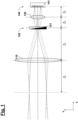
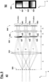
- Fig. 1 shows a schematic representation to explain the principle underlying the present invention and the basic structure of a system according to the invention for beam analysis.
- a collimated beam of rays first strikes a first Fourier optics 110 along the z-direction in the coordinate system shown and is focused by this onto a gray gradient filter arrangement 120, which is arranged in the optical beam path in a far-field plane of the beam guidance optics (sometimes also referred to as a “spatial filter plane”) and in the exemplary embodiment shown has a single gray graduated filter 121 with a transmission curve that is linear in the y-direction (and only indicated schematically by a wedge).
- the radiation transmitted through the gray graduated filter arrangement 120 or the gray graduated filter 121 passes through a second Fourier optics 130 to a light intensity sensor arrangement 140 arranged in a near-field plane of the beam guiding optics, which in the exemplary embodiment has a single light intensity sensor 141 which has one over the entire sensor surface integrated intensity value measures.
- the invention is not limited to a specific embodiment, with refractive, diffractive, diffractive multifocal or reflective designs being possible in particular. If necessary, the second Fourier optics 130 can also be omitted if the light intensity sensor 141 is sufficiently uniform.
- the invention is not limited to a specific embodiment with regard to the design of the light intensity sensor arrangement 140 or the light intensity sensor 141, wherein the light intensity sensor 141 can be designed, for example, photovoltaic, photoconductive, pyro-electromagnetic or even thermal or bolometric.
- the gray gradient filter(s) 121 of the gray gradient filter arrangement 120 can be designed as a surface absorber or volume absorber (e.g. wedge), possibly also retroreflecting.
- the arrangement of the gray graduated filter 141 (according to Fig. 1 in the "intervention plane" of a Kepler telescope) has the advantageous consequence that a near-field plane becomes accessible for the placement of the light intensity sensor 141, which is characterized, among other things, by the fact that the shape and size of the "intensity structure" present there with correct afocal coupling in the optical beam path is independent of beam direction and beam divergence and the energy of the electromagnetic radiation is sufficiently diluted to avoid local saturation effects.
- all main sources of interference are either - as in the case of beam direction and divergence - eliminated or - as in the case of beam decentering and variation of the beam size - at least sufficiently suppressed, so that disturbing artifacts of the light intensity sensor (in particular its spatial inhomogeneity and saturation) are not or only come into play to a significantly reduced extent.
- a gray graduated filter arrangement 520 made up of three gray graduated filters 521-523 can be used in combination with a light intensity sensor arrangement 540 made up of three light intensity sensors 541-543, with a first of the gray graduated filters 521 having a linear transmission curve in the y direction based on the coordinate system shown second of the gray graduated filters 523 has a transmission curve that is linear in the y direction and a third of the gray graduated filters 522 has a constant transmission curve for the purpose of intensity normalization.
- a collimated beam of rays first strikes a diffractive structure or an optical grating 505 along the z-direction in the drawn coordinate system, through which the beam of rays is replicated into partial rays, which are only spatially separated from one another and otherwise have identical optical beam properties to one another and.
- This replication takes place in the three diffraction orders "+1", "0" and "-1".
- the design is preferably chosen so that the partial beams are exposed to the maximum diameter d max and the maximum Position variation r max (each based on the far field plane) can be separated in such a way that a disturbing interaction as a result of interference effects is avoided.
- the gray graduated filter arrangement 520 has a (eg monolithic) arrangement of gray graduated filters 521-523 (gray filter array), which are as in Fig. 5b can be designed indicated in plan view. Furthermore, according to Fig. 5a the output-side Fourier optics 130 and the light intensity sensor 140 from Fig. 1 replaced by a (eg also monolithic) arrangement of several Fourier optics (in the form of a lens array) 531-533 or an arrangement of several light intensity sensors 541-543.
- s denotes the position coordinate in the direction of progression
- s 0 the position of the transmission value 1 ⁇ 2
- W the width of the zone of the complete increase in transmission from the value zero to the value one.
- the parameters W x and W y as well as x 0 and y 0 characterize the two gray gradient filters 521, 523 with a linear transmission curve.
- the parameters ⁇ 1 to ⁇ 3 represent the detection sensitivities of the channels, which can vary for different reasons (e.g. component fluctuations, etc.).
- the design parameters can be summarized into four effective parameters, two offset values C x and C y and two gain values G x and G y , which can be determined, for example, by calibration and are therefore referred to below as calibration parameters.
- a laser plasma source such as the one in Fig. 14
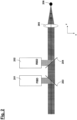
- a possible basic structure for what purpose Fig. 2 shows a schematic representation of a possible, basic overall structure.
- both laser beams in the "forward direction" (before hitting the respective target droplet) and laser beams in the "backward direction” (ie the infrared radiation reflected back by the respective target droplet) are evaluated.
- FIG. 2 A part of the incident laser beam with a Gaussian profile is coupled out at a first partially transparent mirror 203 and with a first analysis unit 201, which in particular is a system analogous to Fig. 1 or Fig. 5 can have, analyzed.
- the part of the incident laser beam passing through the partially transparent mirror 203 and another partially transparent mirror 204 reaches a metallic target (e.g. tin) droplet 206 via a focusing optics 205, where part of the laser beam is reflected back and collimated via the focusing optics 205 to the partially transparent mirror 204 returned.
- a metallic target e.g. tin
- part of the laser beam is in turn coupled out to a second analysis unit 202, which is also in particular a system analogous to Fig. 1 or Fig. 5 can have.
- beam traps can be provided to collect the unused portion of the radiation impinging on the partially transparent mirror 203 or 204.
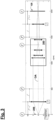
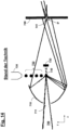
- FIG. 3 A schematic beam path for analyzing the laser beam in the "reverse direction” is shown in Fig. 3 shown, with field levels labeled “F” and pupil levels labeled “P”.
- a shift in the position of the target droplet 206 results in a change in the measurement result obtained with the light intensity sensor arrangement.
- the analysis of the laser beams both in the “forward direction” (laser beam before hitting the respective target droplet 206, “forward beam”) and in the “backward direction” (laser beam after reflection on the respective target droplet 206, “backward beam”) allows this Statement about the relative setting of the laser beam and target droplets 206 to one another, whereby - with renewed reference to Fig. 1 - the setting or focus position of the laser beam can be determined from the result obtained with the first analysis unit 201 and the droplet position can be concluded from the result obtained with the second analysis unit 202.
- the object and image-side focal lengths f' and f as well as the telescope image scale mag are determined using Fig. 3 clearly (object space painted, image space unpainted), and the positions z' and z refer to the focal plane of the respective Fourier optics.
- a sharp image occurs when all rays emanating from an object point are brought together in one image point, regardless of the beam angle.
- the focus condition is accordingly
- I ( x,y;z ) denotes the light intensity for the selected cutting plane.
- a suitable "artificial" apodization In one embodiment, a (in the above sense "soft") apodization u x y e.g NF ⁇ x 2 + y 2 ⁇ R N/A ⁇ u x y e.g NF A R N/A x y can be realized by introducing a structured gray filter with a corresponding profile into the near field or into a pupil plane.
- R x y 1 2 1 + cos ⁇ x 2 + y 2 R with the trimming radius R in the area around R NA .
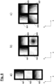
- Fig. 6a shows a linear arrangement of three gray gradient filters 621-623, as in the structure of Fig. 5 is used.
- Fig. 6b shows a (for example with regard to existing installation space restrictions) folded 2-D arrangement of four gray graduated filters (or "channels"), which have the gray graduated filters 621-623 of Fig. 6a also has an additional gray gradient filter 625 that is radially parabolic in its transmission curve (for the purpose of spot size measurement or adjustment).
- Fig. 6c shows a redundant folded 2-D arrangement, which, in addition to two gray graduated filters 621, 623 with a linear transmission curve in the x and y direction, has two gray graduated filters 626, 627 with a linear transmission curve in the diagonal (45 °) direction.
- the gray gradient filter 622 with a constant transmission curve is omitted, assuming that the signal for intensity normalization is available elsewhere.
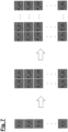
- Fig. 7 illustrates the arbitrary arrangement of gray gradient filters starting from a linear arrangement to a 2D matrix arrangement.
- Energy normalization can also be derived by using pairs of opposing gray gradient filters (or “wedge gradient filters”). This will be briefly explained below for the in Fig. 8a gray gradient filter arrangement 821 shown as an example, which has two linear transmission curves in the positive or negative x or y direction for measuring the focus position coordinates of a laser beam to be characterized.
- a uniform gain value G and a uniform (“wedge") width W of the linear transmission curve are assumed for all gray graduated filters.
- the "wedge displacements" x 1 and y 3 are also chosen to be the same in pairs.
- I stands for the total intensity integrated across the light structure
- the two sum signals "S 1 +S 2 " and “S 3 +S 4 " each result in the total intensity according to the system of equations (23). This can be used to normalize the two difference signals in order to ultimately extract the desired center of gravity positions.
- Second-order gray graduated filters which have a parabolic transmission curve, offer the possibility of measuring the second moments of the light distribution and thus the size of the light beam to be analyzed (or the "light structure").
- s denotes the position coordinate in the direction of progression
- s 0 the position of the apex
- W the width of the area over which the complete increase in the transmission coefficient from the value zero to the value one occurs.
- Fig. 8b shows an example and schematic of an embodiment of a gray graduated filter arrangement 822 with five gray graduated filters (or “measuring channels"), which have a gray graduated filter with a linear transmission curve in the x direction, a gray graduated filter with a linear transmission curve in the y direction, a uniform gray graduated filter with a constant transmission curve as Reference, a gray graduated filter with a parabolic transmission curve in the x direction and a gray graduated filter with a parabolic transmission curve in the y direction.
- the parameters W 1 , W 2 , W 4 and W 5 as well as x 1 , y 2 , x 4 and y 5 characterize the four gray gradient filters.
- the parameters ⁇ 1 to ⁇ 5 represent the detection sensitivities of the channels, the variation of which can have various causes (e.g. component fluctuations, etc.).
- the design parameters are partially summarized into effective parameters. These then remain to be determined by calibration or other means the two offset values C 1 and C 2 , the four gain values G 1 , G 2 , G 4 and G 5 as well as the two vertex positions x 4 and y 5 .
- second-order gray gradient filters also provide metrological access to the beam size parameters w x 2 and w y 2 .
- a focus position and focus size sensor When using spatially shifted parabolic transmission curves, it is also possible to realize a focus position and focus size sensor that does not require the use of linear transmission curves.
- An exemplary embodiment of such a gray graduated filter arrangement 824 is shown in Fig. 8d shown. The principle is based on pairs of parabolic gray gradient filters, whose vertices are shifted in pairs in opposite directions along the axis.
- a uniform gain value G is assumed for all gray gradient filters (or "channels").
- the scheme described above can be continued as desired to measure higher order moments.
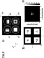
- Fig. 9a-c an embodiment of a gray graduated filter arrangement 920 using four gray graduated filters 921-924 is examined in more detail.
- Fig. 9a symbolize the lenses of the lens arrangement following the gray gradient filter arrangement 920, and the rounded dashed squares symbolize the light intensity sensors of the light intensity sensor arrangement.
- a parasitic zeroth diffraction order and the higher parasitic diffraction orders are not transmitted.
- a 2D grid is required which concentrates the energy into the first four diagonal diffraction orders.
- hybrid ie designed as a combined amplitude-phase DOE
- checkerboard grid design binary grid (checkerboard grid design)
- Fig. 9b shows a unit cell of the hybrid checkerboard grating optimized for energy concentration in the first four diagonal diffraction orders.
- White areas have transmission 1 and have a constant phase corresponding to the value specified in the field.
- Fig. 9c shows the strength of the diffraction order. Thanks to the special grid design, 89% of the transmitted light is transmitted Energy is concentrated in the first four diagonal diffraction orders. In particular, for an ideally manufactured grating, neither the zeroth nor all higher orders of diffraction occur.
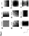
- Fig. 11a-c and Fig. 12a-d show schematic representations to explain specific embodiments of a gray gradient filter with binary sub-wavelength structures that can be used in the context of the present invention. These embodiments take into account the fact that, in the concept according to the invention, comparatively high demands are placed on the quality of the gray graduated filter(s) used, since this directly determines the accuracy achieved in the position measurement and any fluctuations in the transmission curve result in corresponding measurement errors in the result in beam analysis.
- each gray gradient filter has a flat, transmitting substrate on which non-transmitting or opaque (i.e. either completely absorbing or completely reflecting) binary sub-wavelength structures are applied.
- a gray graduated filter can have a size of approximately 1mm ⁇ 1mm and be printed with a structure of 1000 ⁇ 1000 pixels, so that structural elements of approximately 1 ⁇ m are produced, the size of which is therefore well below the exemplary wavelength of approximately 10.6 ⁇ m of a light beam to be analyzed is in the long-wave infrared range.
- Such sub-wavelength structures have a period smaller than the wavelength, which means that no defined diffraction occurs (i.e virtually only the zeroth order is transmitted).
- the binary structures according to the invention are now arranged in such a way that, averaged over a certain range (approximately corresponding to the spot size of the light beam to be analyzed), effective transmission values or gray values between zero and one are obtained on average.
- Fig. 11a-b Embodiment shows Fig. 11a the realized transmission curve (gray gradient) 961, and Fig. 11b shows the binary structure 962 used for this purpose. As shown in the corresponding Fourier transformation 963 Fig. 11c As can be seen, no undesirable periodic structures occur.
- T eff ⁇ ⁇ ⁇ + ⁇ dx dy I 0 x y T x y ⁇ ⁇ ⁇ + ⁇ dx dy I 0 x y
- l 0 (x,y) is the incoming intensity distribution and T(x,y) is the (binary) transmission of the gray graduated filter.
- T(x,y) is the (binary) transmission of the gray graduated filter.
- a sufficiently large number of binary structural elements must be located in the integration range of the beam.
- the steel can cover approximately 100 ⁇ 100 structural elements.
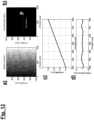
- Fig. 12b moves in a simulation for the in Fig. 12a shown binary sub-wavelength structure of a gray graduated filter a Gaussian light spot from left to right, whereby in the plot of Fig. 12c for those through the Gray gradient filter transmitted light intensity results in very good linearity (in particular without undesirable granularities due to the structural elements).
- An in Fig. 12d The position error shown, resulting from the very small deviations from linearity, is well below 1 ⁇ m over a distance of approximately 600 ⁇ m, so that a very good ratio of measurement error to measurement range is obtained.
Landscapes
- Physics & Mathematics (AREA)
- Optics & Photonics (AREA)
- General Physics & Mathematics (AREA)
- Spectroscopy & Molecular Physics (AREA)
- Engineering & Computer Science (AREA)
- Plasma & Fusion (AREA)
- Photometry And Measurement Of Optical Pulse Characteristics (AREA)
- Exposure Of Semiconductors, Excluding Electron Or Ion Beam Exposure (AREA)
- Exposure And Positioning Against Photoresist Photosensitive Materials (AREA)
Claims (12)
- Système permettant d'analyser un faisceau lumineux collimaté guidé par une optique de guidage de faisceau, comprenant• une première optique de Fourier (110, 510) formée par une première lentille de focalisation ayant une première focale (f1) ;• un agencement de filtre gradué neutre (120, 520) qui est disposé après la première lentille de focalisation à la distance de la première focale (f1) par rapport à la trajectoire du faisceau ;• une deuxième optique de Fourier (130, 531, 532, 533) formée par une deuxième lentille de focalisation ayant une deuxième focale (f2) qui est disposée après l'agencement de filtre gradué neutre (120, 520) à la distance de la deuxième focale (f2) par rapport à la trajectoire du faisceau ; et• un agencement de capteur d'intensité de lumière (140, 540) qui est disposé après la deuxième lentille de focalisation à la distance de la deuxième focale (f2) par rapport à la trajectoire du faisceau, dans lequel l'agencement de capteur d'intensité de lumière (140, 540) présente au moins un capteur d'intensité de lumière (141, 541, 542, 543) ;• dans lequel l'agencement de capteur d'intensité de lumière (140, 540) est configuré de telle sorte qu'il mesure pour chaque filtre gradué neutre (121, 521, 522, 523) de l'agencement de filtre gradué neutre (120, 520) respectivement l'intensité de lumière transmise à travers ce filtre gradué neutre ; et• dans lequel l'agencement de filtre gradué neutre présente un premier filtre gradué neutre (521) ayant une courbe de transmission linéaire dans une première direction spatiale et un deuxième filtre gradué neutre (523) ayant une courbe de transmission linéaire dans une deuxième direction spatiale différente de la première direction spatiale, et/ou dans lequel l'agencement de filtre gradué neutre présente au moins un filtre gradué neutre ayant une courbe de transmission parabolique au moins dans une direction spatiale prédéterminée.
- Système selon la revendication 1, caractérisé en ce que l'agencement de filtre gradué neutre présente au moins un filtre gradué neutre qui présente une courbe de transmission ayant une géométrie en forme de paraboloïde de révolution ou en forme de selle.
- Système selon la revendication 1 ou 2, caractérisé en ce que l'agencement de filtre gradué neutre présente au moins un filtre gradué neutre (522) qui dispose d'une courbe de transmission constante afin de permettre une normalisation de l'intensité.
- Système selon l'une quelconque des revendications précédentes, caractérisé en ce que l'agencement de filtre gradué neutre (520) présente un réseau d'une pluralité de filtres gradués neutres (521, 522, 523).
- Système selon l'une quelconque des revendications précédentes, caractérisé en ce que l'agencement de capteur d'intensité de lumière (540) présente un réseau d'une pluralité de capteurs d'intensité de lumière (541, 542, 543).
- Système selon l'une quelconque des revendications précédentes, caractérisé en ce qu'il présente une structure (505) de séparation de faisceau, disposée en amont de l'agencement de filtre gradué neutre (520) par rapport à la direction de propagation de la lumière, afin de séparer le faisceau lumineux à analyser en une pluralité de faisceaux partiels.
- Système selon la revendication 6, caractérisé en ce que cette structure de séparation de faisceau (505) est disposée devant la première lentille de focalisation à la distance de la première focale (f1) par rapport à la trajectoire du faisceau.
- Système selon l'une quelconque des revendications précédentes, caractérisé en ce que l'agencement de filtre gradué neutre présente au moins un filtre gradué neutre qui est formé par des structures binaires, dans lequel les dimensions de structure de ces structures binaires sont inférieures à la longueur d'onde du faisceau lumineux à analyser.
- Système selon l'une quelconque des revendications précédentes, caractérisé en ce que le faisceau lumineux à analyser est un faisceau laser, en particulier un faisceau laser ayant une longueur d'onde dans le domaine des infrarouges.
- Procédé permettant d'analyser un faisceau lumineux collimaté guidé par une optique de guidage de faisceau• dans lequel un faisceau lumineux à analyser est focalisée par une première optique de Fourier (110, 510) formée par une première lentille de focalisation ayant une première focale (f1) sur un agencement de filtre gradué neutre (120, 520) se trouvant après la première lentille de focalisation à la distance de la première focale (f1) par rapport à la trajectoire du faisceau ;• dans lequel, par rapport à la trajectoire du faisceau, après l'agencement de filtre gradué neutre (120, 520), une deuxième optique de Fourier (130, 531, 532, 533) formée par une deuxième lentille de focalisation est disposée à la distance de la deuxième focale (f2) ;• dans lequel un agencement de capteur d'intensité de lumière (140, 540), qui est disposé après la deuxième lentille de focalisation à la distance de la deuxième focale (f2) par rapport à la trajectoire du faisceau et présente au moins un capteur d'intensité de lumière (141, 541, 542, 543), mesure pour chaque filtre gradué neutre (121, 521, 522, 523), l'agencement de filtre gradué neutre (120, 520) respectivement l'intensité de lumière transmise à travers ce filtre gradué neutre ;• dans lequel l'agencement de filtre gradué neutre présente un premier filtre gradué neutre (521) ayant une courbe de transmission linéaire dans une première direction spatiale, et un deuxième filtre gradué neutre (523) ayant une courbe de transmission linéaire dans une deuxième direction spatiale différente de la première direction spatiale, et/ou dans lequel l'agencement de filtre gradué neutre présente au moins un filtre gradué neutre ayant au moins une courbe de transmission parabolique dans une direction spatiale prédéterminée.
- Utilisation d'un filtre gradué neutre dans un système selon l'une quelconque des revendications 1 à 9, dans lequel le filtre gradué neutre est formé par des structures binaires, et dans lequel les dimensions de structure de ces structures binaires sont inférieures à la longueur d'onde d'un faisceau lumineux à analyser.
- Utilisation d'un filtre gradué neutre selon la revendication 11, caractérisé en ce que le faisceau lumineux à analyser dispose d'une longueur d'onde dans le domaine des infrarouges.
Applications Claiming Priority (2)
| Application Number | Priority Date | Filing Date | Title |
|---|---|---|---|
| DE102014208792.9A DE102014208792A1 (de) | 2014-05-09 | 2014-05-09 | System und Verfahren zur Analyse eines von einer Strahlführungsoptik geführten Lichtstrahls |
| PCT/EP2015/060145 WO2015169937A1 (fr) | 2014-05-09 | 2015-05-08 | Système et procédé d'analyse d'un faisceau lumineux guidé par une optique de guidage de faisceau |
Publications (4)
| Publication Number | Publication Date |
|---|---|
| EP3140628A1 EP3140628A1 (fr) | 2017-03-15 |
| EP3140628C0 EP3140628C0 (fr) | 2023-08-09 |
| EP3140628B1 EP3140628B1 (fr) | 2023-08-09 |
| EP3140628B9 true EP3140628B9 (fr) | 2023-10-25 |
Family
ID=53267309
Family Applications (1)
| Application Number | Title | Priority Date | Filing Date |
|---|---|---|---|
| EP15724539.0A Active EP3140628B9 (fr) | 2014-05-09 | 2015-05-08 | Système et procédé d'analyse d'un faisceau lumineux guidé par une optique de guidage de faisceau |
Country Status (7)
| Country | Link |
|---|---|
| US (1) | US9823119B2 (fr) |
| EP (1) | EP3140628B9 (fr) |
| JP (1) | JP6576435B2 (fr) |
| DE (1) | DE102014208792A1 (fr) |
| ES (1) | ES2961538T3 (fr) |
| PL (1) | PL3140628T3 (fr) |
| WO (1) | WO2015169937A1 (fr) |
Families Citing this family (7)
| Publication number | Priority date | Publication date | Assignee | Title |
|---|---|---|---|---|
| DE102015211999A1 (de) * | 2015-06-29 | 2016-12-29 | Trumpf Werkzeugmaschinen Gmbh + Co. Kg | Laserbearbeitungskopf und Laserbearbeitungsmaschine damit |
| WO2017163345A1 (fr) * | 2016-03-23 | 2017-09-28 | ギガフォトン株式会社 | Appareil de génération de lumière ultraviolette extrême, et procédé de commande de position de centre de gravité de lumière ultraviolette extrême |
| DE102017102998A1 (de) * | 2017-02-15 | 2018-02-08 | Carl Zeiss Smt Gmbh | Anordnung und Verfahren zur Charakterisierung eines transparenten Substrats |
| KR20200092962A (ko) * | 2017-11-29 | 2020-08-04 | 에이에스엠엘 네델란즈 비.브이. | 레이저 빔 모니터링 시스템 |
| DE102018124342A1 (de) | 2018-10-02 | 2020-04-02 | Carl Zeiss Smt Gmbh | Vorrichtung und Verfahren zur Strahlwinkelmessung eines von einer Strahlführungsoptik geführten Lichtstrahls |
| DE102018124396A1 (de) | 2018-10-02 | 2020-04-02 | Carl Zeiss Smt Gmbh | Metrologiesystem und Verfahren zur Vermessung eines Anregungs-Laserstrahls in einer EUV-Plasmaquelle |
| CN113960804B (zh) * | 2021-10-21 | 2023-08-08 | 四川大学 | 一种连续光谱色温合成装置及合成方法 |
Family Cites Families (13)
| Publication number | Priority date | Publication date | Assignee | Title |
|---|---|---|---|---|
| US3538335A (en) * | 1968-11-27 | 1970-11-03 | Gen Electric | Light intensity controller for photosensitive pickup tubes |
| JPS5230799B2 (fr) * | 1972-10-27 | 1977-08-10 | ||
| GB1434304A (en) * | 1973-05-16 | 1976-05-05 | Ciba Geigy Ag | Optical apparatus |
| US4037959A (en) * | 1975-12-15 | 1977-07-26 | The United States Of America As Represented By The Secretary Of The Navy | Means for real-time laser source characterization |
| FR2470397A1 (fr) * | 1979-11-21 | 1981-05-29 | Thomson Csf | Attenuateur optique a attenuation controlee |
| JPH0640023B2 (ja) * | 1986-09-25 | 1994-05-25 | 株式会社神戸製鋼所 | 光入力の位置・分散検出方法および装置 |
| US5329350A (en) | 1992-05-21 | 1994-07-12 | Photon, Inc. | Measuring laser beam parameters using non-distorting attenuation and multiple simultaneous samples |
| DE19822924C2 (de) * | 1998-05-22 | 2000-06-15 | Daimler Chrysler Ag | Verfahren und Vorrichtung zur Messung der Verteilung der Energiefeldichte eines Laserstrahls |
| US8237922B2 (en) | 2010-04-08 | 2012-08-07 | Haas Laser Technologies, Inc. | Laser beam analysis apparatus |
| DE102010053323B3 (de) * | 2010-12-02 | 2012-05-24 | Xtreme Technologies Gmbh | Verfahren zur räumlich aufgelösten Messung von Parametern in einem Querschnitt eines Strahlenbündels energiereicher Strahlung mit hoher Intensität |
| DE102012204674B4 (de) * | 2012-03-23 | 2014-11-27 | Carl Zeiss Smt Gmbh | Strahlregelungsvorrichtung für einen EUV-Beleuchtungsstrahl |
| DE102013224583A1 (de) | 2013-11-29 | 2015-06-03 | Carl Zeiss Smt Gmbh | Messanordnung zur Verwendung bei der Trajektorienbestimmung fliegender Objekte |
| DE102014201779B4 (de) | 2014-01-31 | 2016-12-15 | Carl Zeiss Smt Gmbh | Strahlpropagationskamera und Verfahren zur Lichtstrahlanalyse |
-
2014
- 2014-05-09 DE DE102014208792.9A patent/DE102014208792A1/de not_active Ceased
-
2015
- 2015-05-08 ES ES15724539T patent/ES2961538T3/es active Active
- 2015-05-08 WO PCT/EP2015/060145 patent/WO2015169937A1/fr active Application Filing
- 2015-05-08 EP EP15724539.0A patent/EP3140628B9/fr active Active
- 2015-05-08 PL PL15724539.0T patent/PL3140628T3/pl unknown
- 2015-05-08 JP JP2017510765A patent/JP6576435B2/ja active Active
-
2016
- 2016-11-09 US US15/347,348 patent/US9823119B2/en active Active
Also Published As
| Publication number | Publication date |
|---|---|
| PL3140628T3 (pl) | 2024-02-26 |
| DE102014208792A1 (de) | 2015-11-12 |
| ES2961538T3 (es) | 2024-03-12 |
| JP2017519222A (ja) | 2017-07-13 |
| JP6576435B2 (ja) | 2019-09-18 |
| US20170122803A1 (en) | 2017-05-04 |
| EP3140628A1 (fr) | 2017-03-15 |
| EP3140628C0 (fr) | 2023-08-09 |
| WO2015169937A1 (fr) | 2015-11-12 |
| EP3140628B1 (fr) | 2023-08-09 |
| US9823119B2 (en) | 2017-11-21 |
Similar Documents
| Publication | Publication Date | Title |
|---|---|---|
| EP3140628B9 (fr) | Système et procédé d'analyse d'un faisceau lumineux guidé par une optique de guidage de faisceau | |
| EP3100011B1 (fr) | Caméra à propagation de faisceaux et procédé d'analyse de faisceaux lumineux | |
| WO2008012091A2 (fr) | Procédé et dispositif de détermination de l'écart d'une forme réelle de la forme nominale d'une surface optique | |
| DE102017131224A1 (de) | Verfahren und Vorrichtung zur Erfassung einer Fokuslage eines Laserstrahls | |
| DE60312406T2 (de) | Apparat und Verfahren zur Messung von optischen Eigenschaften eines diffraktiven optischen Elements | |
| WO2020253898A1 (fr) | Système et procédé de contrôle de position focale | |
| DE102013218991A1 (de) | Vorrichtung zum Bestimmen einer optischen Eigenschaft eines optischen Abbildungssystems | |
| DE102016212464A1 (de) | Messvorrichtung zum Bestimmen eines Wellenfrontfehlers | |
| EP3359928B1 (fr) | Procédé et dispositif d'analyse de faisceau | |
| EP3861310B9 (fr) | Système de métrologie et procédé pour mesurer un faisceau laser d'excitation dans une source de plasma ultraviolet extrême | |
| EP1197736A2 (fr) | Procédé et dispositif de caractérisation interférométrique résolue dans l'espace et dans le temps d'impulsions laser ultracourtes | |
| DE102022209651A1 (de) | Verfahren zum Bearbeiten eines Referenzelements für ein Interferometer | |
| DE102015209489A1 (de) | Interferometrische Messvorrichtung | |
| DE102013224583A1 (de) | Messanordnung zur Verwendung bei der Trajektorienbestimmung fliegender Objekte | |
| DE102014010667A1 (de) | Verfahren und Vorrichtung zur Messung der Form einer Wellenfront eines optischen Strahlungsfeldes | |
| DE102007062825A1 (de) | Gitterspiegel zur Online-Überwachung eines Laserstrahls und Überwachungsvorrichtung damit | |
| DE102008001448A1 (de) | Verfahren und Vorrichtung zum Messen mindestens eines Abbildungsfehlers eines optischen Abbildungssystems | |
| DE102018130162A1 (de) | Verfahren, Interferometer und Signalverarbeitungsvorrichtung, jeweils zur Bestimmung einer Eingangsphase und/oder einer Eingangsamplitude eines Eingangslichtfelds | |
| DE10113017A1 (de) | System zur interferometrischen Messung von optisch wirksamen Fehlern von optischen Baugruppen | |
| DE19841083C2 (de) | Verfahren zur Charakterisierung eines Strahlenbündels | |
| WO2022128998A1 (fr) | Dispositif et procédé de détermination de la position d'un point de concentration | |
| DE102021212993A1 (de) | Verfahren zur Messung einer Absorption einer elektromagnetischen Strahlung durch ein optisches Element, Vorrichtung zur Messung einer Umformungseigenschaft eines optischen Elements und Lithografiesystem | |
| EP2893389B1 (fr) | Procédé et dispositif destinés à focaliser de la lumière laser | |
| DE102010038648A1 (de) | Vorrichtung und Verfahren zur Bestimmung der Divergenz und/oder Wellenfrontkrümmung eines Strahlbündels sowie Laserkristallisationsvorrichtung | |
| DE102020209686A1 (de) | Messvorrichtung zur interferometrischen Formvermessung einer Oberfläche eines Testobjekts |
Legal Events
| Date | Code | Title | Description |
|---|---|---|---|
| STAA | Information on the status of an ep patent application or granted ep patent |
Free format text: STATUS: THE INTERNATIONAL PUBLICATION HAS BEEN MADE |
|
| PUAI | Public reference made under article 153(3) epc to a published international application that has entered the european phase |
Free format text: ORIGINAL CODE: 0009012 |
|
| STAA | Information on the status of an ep patent application or granted ep patent |
Free format text: STATUS: REQUEST FOR EXAMINATION WAS MADE |
|
| 17P | Request for examination filed |
Effective date: 20161108 |
|
| AK | Designated contracting states |
Kind code of ref document: A1 Designated state(s): AL AT BE BG CH CY CZ DE DK EE ES FI FR GB GR HR HU IE IS IT LI LT LU LV MC MK MT NL NO PL PT RO RS SE SI SK SM TR |
|
| AX | Request for extension of the european patent |
Extension state: BA ME |
|
| DAV | Request for validation of the european patent (deleted) | ||
| DAX | Request for extension of the european patent (deleted) | ||
| STAA | Information on the status of an ep patent application or granted ep patent |
Free format text: STATUS: EXAMINATION IS IN PROGRESS |
|
| 17Q | First examination report despatched |
Effective date: 20180625 |
|
| STAA | Information on the status of an ep patent application or granted ep patent |
Free format text: STATUS: EXAMINATION IS IN PROGRESS |
|
| STAA | Information on the status of an ep patent application or granted ep patent |
Free format text: STATUS: EXAMINATION IS IN PROGRESS |
|
| RIC1 | Information provided on ipc code assigned before grant |
Ipc: H05G 2/00 20060101ALI20230201BHEP Ipc: G01J 1/04 20060101ALI20230201BHEP Ipc: G01J 1/42 20060101AFI20230201BHEP |
|
| GRAP | Despatch of communication of intention to grant a patent |
Free format text: ORIGINAL CODE: EPIDOSNIGR1 |
|
| STAA | Information on the status of an ep patent application or granted ep patent |
Free format text: STATUS: GRANT OF PATENT IS INTENDED |
|
| INTG | Intention to grant announced |
Effective date: 20230314 |
|
| GRAS | Grant fee paid |
Free format text: ORIGINAL CODE: EPIDOSNIGR3 |
|
| GRAA | (expected) grant |
Free format text: ORIGINAL CODE: 0009210 |
|
| STAA | Information on the status of an ep patent application or granted ep patent |
Free format text: STATUS: THE PATENT HAS BEEN GRANTED |
|
| AK | Designated contracting states |
Kind code of ref document: B1 Designated state(s): AL AT BE BG CH CY CZ DE DK EE ES FI FR GB GR HR HU IE IS IT LI LT LU LV MC MK MT NL NO PL PT RO RS SE SI SK SM TR |
|
| REG | Reference to a national code |
Ref country code: GB Ref legal event code: FG4D Free format text: NOT ENGLISH |
|
| REG | Reference to a national code |
Ref country code: CH Ref legal event code: EP |
|
| REG | Reference to a national code |
Ref country code: IE Ref legal event code: FG4D Free format text: LANGUAGE OF EP DOCUMENT: GERMAN |
|
| REG | Reference to a national code |
Ref country code: DE Ref legal event code: R096 Ref document number: 502015016532 Country of ref document: DE |
|
| REG | Reference to a national code |
Ref country code: CH Ref legal event code: PK Free format text: BERICHTIGUNG B9 |
|
| U01 | Request for unitary effect filed |
Effective date: 20230828 |
|
| U07 | Unitary effect registered |
Designated state(s): AT BE BG DE DK EE FI FR IT LT LU LV MT NL PT SE SI Effective date: 20230904 |
|
| PG25 | Lapsed in a contracting state [announced via postgrant information from national office to epo] |
Ref country code: GR Free format text: LAPSE BECAUSE OF FAILURE TO SUBMIT A TRANSLATION OF THE DESCRIPTION OR TO PAY THE FEE WITHIN THE PRESCRIBED TIME-LIMIT Effective date: 20231110 |
|
| PG25 | Lapsed in a contracting state [announced via postgrant information from national office to epo] |
Ref country code: IS Free format text: LAPSE BECAUSE OF FAILURE TO SUBMIT A TRANSLATION OF THE DESCRIPTION OR TO PAY THE FEE WITHIN THE PRESCRIBED TIME-LIMIT Effective date: 20231209 |
|
| PG25 | Lapsed in a contracting state [announced via postgrant information from national office to epo] |
Ref country code: RS Free format text: LAPSE BECAUSE OF FAILURE TO SUBMIT A TRANSLATION OF THE DESCRIPTION OR TO PAY THE FEE WITHIN THE PRESCRIBED TIME-LIMIT Effective date: 20230809 Ref country code: NO Free format text: LAPSE BECAUSE OF FAILURE TO SUBMIT A TRANSLATION OF THE DESCRIPTION OR TO PAY THE FEE WITHIN THE PRESCRIBED TIME-LIMIT Effective date: 20231109 Ref country code: IS Free format text: LAPSE BECAUSE OF FAILURE TO SUBMIT A TRANSLATION OF THE DESCRIPTION OR TO PAY THE FEE WITHIN THE PRESCRIBED TIME-LIMIT Effective date: 20231209 Ref country code: HR Free format text: LAPSE BECAUSE OF FAILURE TO SUBMIT A TRANSLATION OF THE DESCRIPTION OR TO PAY THE FEE WITHIN THE PRESCRIBED TIME-LIMIT Effective date: 20230809 Ref country code: GR Free format text: LAPSE BECAUSE OF FAILURE TO SUBMIT A TRANSLATION OF THE DESCRIPTION OR TO PAY THE FEE WITHIN THE PRESCRIBED TIME-LIMIT Effective date: 20231110 |
|
| REG | Reference to a national code |
Ref country code: ES Ref legal event code: FG2A Ref document number: 2961538 Country of ref document: ES Kind code of ref document: T3 Effective date: 20240312 |
|
| PG25 | Lapsed in a contracting state [announced via postgrant information from national office to epo] |
Ref country code: SM Free format text: LAPSE BECAUSE OF FAILURE TO SUBMIT A TRANSLATION OF THE DESCRIPTION OR TO PAY THE FEE WITHIN THE PRESCRIBED TIME-LIMIT Effective date: 20230809 Ref country code: RO Free format text: LAPSE BECAUSE OF FAILURE TO SUBMIT A TRANSLATION OF THE DESCRIPTION OR TO PAY THE FEE WITHIN THE PRESCRIBED TIME-LIMIT Effective date: 20230809 Ref country code: CZ Free format text: LAPSE BECAUSE OF FAILURE TO SUBMIT A TRANSLATION OF THE DESCRIPTION OR TO PAY THE FEE WITHIN THE PRESCRIBED TIME-LIMIT Effective date: 20230809 Ref country code: SK Free format text: LAPSE BECAUSE OF FAILURE TO SUBMIT A TRANSLATION OF THE DESCRIPTION OR TO PAY THE FEE WITHIN THE PRESCRIBED TIME-LIMIT Effective date: 20230809 |