EP3140566B1 - Centrifugal pendulum absorber with axial roller bearing - Google Patents
Centrifugal pendulum absorber with axial roller bearing Download PDFInfo
- Publication number
- EP3140566B1 EP3140566B1 EP15721556.7A EP15721556A EP3140566B1 EP 3140566 B1 EP3140566 B1 EP 3140566B1 EP 15721556 A EP15721556 A EP 15721556A EP 3140566 B1 EP3140566 B1 EP 3140566B1
- Authority
- EP
- European Patent Office
- Prior art keywords
- pendulum
- flange
- centrifugal
- ball
- mass
- Prior art date
- Legal status (The legal status is an assumption and is not a legal conclusion. Google has not performed a legal analysis and makes no representation as to the accuracy of the status listed.)
- Active
Links
- 239000006096 absorbing agent Substances 0.000 title claims description 8
- 238000005096 rolling process Methods 0.000 claims description 10
- 238000002485 combustion reaction Methods 0.000 description 5
- 230000010355 oscillation Effects 0.000 description 5
- 125000006850 spacer group Chemical group 0.000 description 5
- 239000007858 starting material Substances 0.000 description 5
- 238000010586 diagram Methods 0.000 description 4
- 230000005484 gravity Effects 0.000 description 4
- 230000005540 biological transmission Effects 0.000 description 3
- 230000008878 coupling Effects 0.000 description 2
- 238000010168 coupling process Methods 0.000 description 2
- 238000005859 coupling reaction Methods 0.000 description 2
- 230000007935 neutral effect Effects 0.000 description 2
- 230000001133 acceleration Effects 0.000 description 1
- 239000003795 chemical substances by application Substances 0.000 description 1
- 230000001419 dependent effect Effects 0.000 description 1
- 238000011161 development Methods 0.000 description 1
- 230000018109 developmental process Effects 0.000 description 1
- 238000006073 displacement reaction Methods 0.000 description 1
- 230000000694 effects Effects 0.000 description 1
- 238000004049 embossing Methods 0.000 description 1
- 238000009434 installation Methods 0.000 description 1
- 239000000314 lubricant Substances 0.000 description 1
- 238000003754 machining Methods 0.000 description 1
- 239000000463 material Substances 0.000 description 1
- 238000004080 punching Methods 0.000 description 1
- 230000003068 static effect Effects 0.000 description 1
- 230000007704 transition Effects 0.000 description 1
Images


Classifications
-
- F—MECHANICAL ENGINEERING; LIGHTING; HEATING; WEAPONS; BLASTING
- F16—ENGINEERING ELEMENTS AND UNITS; GENERAL MEASURES FOR PRODUCING AND MAINTAINING EFFECTIVE FUNCTIONING OF MACHINES OR INSTALLATIONS; THERMAL INSULATION IN GENERAL
- F16F—SPRINGS; SHOCK-ABSORBERS; MEANS FOR DAMPING VIBRATION
- F16F15/00—Suppression of vibrations in systems; Means or arrangements for avoiding or reducing out-of-balance forces, e.g. due to motion
- F16F15/10—Suppression of vibrations in rotating systems by making use of members moving with the system
- F16F15/14—Suppression of vibrations in rotating systems by making use of members moving with the system using masses freely rotating with the system, i.e. uninvolved in transmitting driveline torque, e.g. rotative dynamic dampers
- F16F15/1407—Suppression of vibrations in rotating systems by making use of members moving with the system using masses freely rotating with the system, i.e. uninvolved in transmitting driveline torque, e.g. rotative dynamic dampers the rotation being limited with respect to the driving means
- F16F15/145—Masses mounted with play with respect to driving means thus enabling free movement over a limited range
Definitions
- the invention relates to a centrifugal pendulum device for arrangement in the drive train of a motor vehicle, with at least one pendulum, which is arranged on a pendulum flange and can perform a relative movement to the pendulum flange along a predetermined pendulum path, in order to assume a variable distance to the axis of rotation of the pendulum flange, the pendulum is arranged between side flanges of the pendulum flange and is supported on rollers which are mounted in elongated holes of the pendulum and the side flanges.
- the invention also relates to a drive train of a motor vehicle with such a centrifugal pendulum device.
- additional movable masses are attached as so-called pendulum masses to a rotating part of the torsional vibration system.
- these masses carry out vibrations on specified paths when they are excited by rotational speed irregularities.
- energy is withdrawn from the exciter oscillation at appropriate times and fed back in, so that the exciter oscillation is damped, i.e. the pendulum mass acts as a vibration absorber. Since both the natural frequency of the centrifugal pendulum oscillation and the exciter frequency are proportional to the speed, a damper effect of a centrifugal pendulum can be achieved over the entire frequency range of the oscillations excited by speed equality.
- a centrifugal pendulum device of the type in question is used, in particular, to reduce vibrations and noises in the drive train of a motor vehicle.
- Such Centrifugal pendulum device comprises at least one pendulum mass, which is suspended from a rotating support element, for example by means of rollers or the like, and can execute a relative movement to the support element along predetermined pendulum tracks, in order to assume a variable distance to the axis of rotation of the support element.
- the structure and function of such a centrifugal pendulum device is for example in DE 10 2006 028 552 A1 described.
- centrifugal pendulums are either, as in the DE 10 2006 028 552 A1 described, arranged on both sides of a carrier disk or, for example, in the DE 10 2012 212 970 A1 described, bordered by two guide plates or side flanges of a pendulum flange.
- Centrifugal pendulum devices according to the preamble of claim 1 are described.
- rims are arranged on both sides of the carrier disk and fix the pendulums in the axial direction with respect to the carrier disk.
- the pendulums usually consist of three layers, these are two outer pendulum masses and a middle pendulum mass.
- the rollers, with which the pendulums are suspended from the side flanges as part of the support element, include a circumferential ring in the middle, which is guided in an elongated hole in the middle pendulum mass with a corresponding clear width and axially fixes the role, since the clear width of the elongated holes that are arranged in outer pendulum masses are smaller than the clear width in the middle pendulum mass.
- the clear width of the elongated holes arranged in the side flanges is in turn smaller than the clear width of those arranged in the outer pendulum masses Elongated holes so that centering rims in the transition from the larger diameter of the roller in the area of the outer pendulum masses to smaller diameters of the roller in the area of the side flanges rest on the inner surfaces of the side flanges and thus center the pendulums axially with respect to the side flanges and prevent the pendulums from running against the side plates.
- centering rims can show an unacceptably high level of wear.
- a centrifugal pendulum device for arrangement in the drive train of a motor vehicle, with at least one pendulum, which is arranged on a pendulum flange and can perform a relative movement to the pendulum flange along a predetermined pendulum path, in order to achieve a variable distance to the axis of rotation of the pendulum flange take, wherein the pendulum is arranged between side flanges of the pendulum flange and is supported on rollers which are mounted in elongated holes of the pendulum and elongated holes of the side flanges, the pendulum being mounted with at least one rolling means opposite at least one of the side flanges.
- the rolling agent acts as a Axial roller bearing, so causes a mounting of the pendulum in the axial direction with respect to the pendulum flange.
- the pendulum is preferably mounted axially opposite at least one of the side flanges with at least one rolling means.
- the centrifugal pendulum device preferably comprises two or more pendulums. If the singular is used below for the pendulum, the information relates to at least one of the several pendulums or to several of the pendulums or all of the pendulums of the centrifugal pendulum device.
- the rolling means is a ball.
- the surfaces on which the rolling means rolls are surface-hardened in one embodiment of the invention.
- the at least one ball is arranged in at least one groove in the pendulum.
- the ball rolls on the bottom of the groove and is guided through its side walls.
- the groove ends can be rounded.
- the groove preferably has a rectangular cross-section with an axial depth that is less than the ball diameter and a radial width that is greater than the ball diameter, so that the ball protrudes over the surface of the pendulum in the axial direction and can roll along the slot with play.
- the pendulum comprises a central pendulum mass and outer pendulum masses arranged on both sides of this, with at least one elongated hole being arranged in at least one of the outer pendulum masses.
- the pendulum comprises a middle pendulum mass and outer pendulum masses arranged on both sides of this.
- the pendulum masses are manufactured individually, for example by punching, and then connected to one another to form the pendulum, the rollers being installed at the same time. Since the pendulum masses are manufactured individually, the middle pendulum mass can be hardened without the outer pendulum masses having to be hardened.
- the elongated hole in the outer pendulum mass creates a groove for guiding the balls during assembly of the pendulum.
- the diameter of the ball is greater than the thickness of the outer pendulum mass.
- the ball protrudes beyond the surface of the pendulum in the axial direction when the groove is formed by an elongated hole in the outer pendulum mass.
- At least one ball preferably two balls, is arranged on both sides of the pendulum.
- the pendulum is mounted on both sides with rolling means and also secured against tilting with at least two balls per side.
- the slots or grooves are curved in one embodiment of the invention.
- the curvature is adapted to the aerial tramway, so that the curvature of the trajectory corresponds to the ball rolling on the pendulum and the side flange. This means that only minimal lateral managers are required for the roles.
- the rollers have a constant diameter in the area of their contact with the outer pendulum masses and the side flanges. Centering rims or the like are therefore dispensed with.
- the roles show the only deviation from the cylindrical shape is a circumferential ring, which is arranged in the larger clear width of the elongated hole of the middle pendulum mass.
- Fig. 1 shows an embodiment of a centrifugal pendulum device 1 according to the invention in a sectional illustration.
- the centrifugal pendulum device 1 is essentially rotationally symmetrical to an axis of rotation R.
- the circumferential direction here means a rotation around the axis of rotation R
- the axial direction means the direction parallel to the axis of rotation R
- the radial direction means a direction perpendicular to the axis of rotation R.
- the centrifugal pendulum device 1 is installed in a drive train between an internal combustion engine with a Crankshaft as a drive shaft and a vehicle clutch, which can be actuated by a release device and whose clutch disc is coupled to a transmission, is arranged.
- the centrifugal pendulum device 1 comprises a flywheel 2, which essentially comprises a cover 3 on the engine side, a spacer ring 4, a pendulum flange 5 and a counter pressure plate 6.
- the pendulum flange 5 carries two pendulums 7, which are mounted pendulum relative to the pendulum flange and thus relative to the flywheel 2, as will be explained in more detail below.
- the motor-side cover 3, the spacer ring 4, the pendulum flange 5 and the counter-pressure plate 6 are firmly connected to one another with rivet bolts 8.
- the motor-side rivet heads 17 of the rivet bolts 8 are arranged in stepped bores so that the rivet heads 17 do not protrude beyond the motor-side surface of the motor-side cover 3.
- the engine-side cover 3, the spacer ring 4 and the pendulum flange 5 each have holes through which the fastening screws 9 protrude, with which the centrifugal pendulum device 1 can be screwed to a crankshaft, not shown, of an internal combustion engine.
- the terms motor-side and gear-side are chosen so that in the installation position in the graphic representation of the Fig.
- the engine-side cover 3 has a centering ring 10 on its inner circumference, the outer side of which rests against the inner circumference of the spacer ring 4 and a roller bearing for centering the transmission input shaft, not shown, can be received on the inner circumference.
- a starter ring gear 11 is fastened to the outer circumference of the cover 3 on the motor side, for example welded or shrunk on or pressed on.
- the starter ring gear 11 has a toothing 12 on its outside, into which a pinion of an electric starter can be meshed in order to start the internal combustion engine.
- the flywheel 2 In the installed position, the flywheel 2 is connected to the crankshaft of the internal combustion engine in a torque-proof manner.
- a clutch cover (not shown here) is connected to the counterpressure plate 6 by means of a pin 13. In addition, there can be further screw or rivet connections between the clutch cover and the counter pressure plate 6.
- the clutch cover carries other elements of the vehicle clutch such.
- B. a pressure plate which is axially displaceable with respect to the counter-pressure plate 6 and means for the axial displacement of the pressure plate.
- the means for axially displacing the pressure plate include, for example, a plate spring which can be actuated mechanically, electrically or hydraulically via a release bearing by a release device such as a central release mechanism or the like.
- the flywheel mass 2 can also be part of a multi-disc clutch or part of a double clutch.
- the engine-side cover 3 comprises an essentially disk-shaped disk part 3a, on the outer circumference of which the starter ring gear 11 is arranged, and in FIG which the stepped bores for the rivet bolts 8 and the bores for the fastening screws 9 are arranged, as well as a conical section 3b which merges into a cylindrical section 3c. Embossings 3d serve to stiffen the cover 3 and, if necessary, to accommodate balancing weights.
- the cylindrical section 3c is pushed onto a shoulder 14 of the counter-pressure plate 6.
- the inner diameter of the cylindrical section 3c corresponds to the outer diameter of the shoulder 14.
- the shoulder 14 enables precise machining of the outer circumference of the counter-pressure plate 6, which is usually manufactured as a stamped and bent component or as a forged component.
- the shoulder 14 can also be dispensed with if necessary.
- a space remains between the cover 3 and the counter-pressure plate 6, into which the pendulum flange 5 with the pendulum 7 protrudes.
- the cylindrical section 3c has at least one opening 15 or a plurality of openings 15 distributed over the circumference which enable or enable a supply of lubricant to the pendulum flange 5 and the pendulum 7.
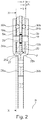
- Fig. 2 shows the pendulum flange 5 with pendulum 7 according to Fig. 1 in a single representation.
- the pendulum flange 5 comprises two side flanges, a side flange 5a on the engine side and a pendulum flange 5b on the gearbox side, between which an annular pendulum receiving space 16 remains.
- the pendulums 7 are mounted by means of rollers 18, the rollers 18 projecting through both side flanges 5a, 5b and the pendulum mass 7.
- the pendulums 7 each include two outer pendulum masses, a motor-side pendulum mass 19a and a clutch-side pendulum mass 19b, between which a middle pendulum mass 20 is arranged.
- the outer pendulum masses 19a, 19b and the middle pendulum mass 20 are by means of rivets 21, see Fig. 3 , firmly connected to each other.
- the side flanges 5a, 5b each include an annular disk-shaped, radially outer pendulum receiving ring 24a, 24b, which each merges into an axially extending hollow cylinder 25a, 25b and this in turn merges into a disk-shaped fastening ring 26a, 26b.
- the fastening rings 26a, 26b lie flat against one another. Due to the hollow cylinders 25a, 25b, the pendulum mounting rings 24a, 24b are each offset in different directions axially to the associated fastening ring 26a, 26b, in the sectional view like a crank, and form an annular mounting space 27 for receiving the pendulum 7.
- Fig. 3 shows the section XX in Fig. 2 and thus a plan view of a pendulum 7.
- a section through the hollow cylinder 25a and a plan view of the fastening ring 26a of the side flange 5a are shown.
- Fig. 4 shows the pendulum 7 in a single representation.
- the roles 18 are, see Fig. 4 , in elongated holes 22a, 22b of the outer pendulum masses 19a, 19b and in elongated holes 23a, 23b of the side flanges 5a, 5b.
- the elongated holes 22, 23 each have a clear width, that is the smallest distance between two opposing walls, which corresponds to the diameter of the rollers 18 plus a play.
- the rollers can therefore be shifted along a center line m of the elongated holes 22a, 22b or a center line n of the elongated holes 23a, 23b.
- elongated holes 28 are arranged, the clear width of which is greater than the clear width of the elongated holes 22a, 22b of the outer pendulum masses 19a, 19b.
- the rollers 18 comprise a circumferential ring 29, which is arranged in the larger clear width of the elongated hole 28 of the central pendulum mass 20. Due to the smaller clear width of the elongated holes 22a, 22b of the outer pendulum masses 19a, 19b, the roller 18 is fixed in the axial direction.
- the link guide allows a pendulum movement of the pendulum 7 around a pendulum center P.
- Fig. 5 shows a schematic diagram of the centrifugal pendulum device 1 according to the invention in a top view in a central position of the pendulum
- Fig. 6 shows the schematic diagram with the pendulum deflected.
- the raceways of the rollers 18 with respect to the pendulum flange 5 or the pendulums 7 are designed in such a way as to compare Fig. 5 that the center of gravity Sp of the pendulum 7 moves on a circular path with a radius I as the pendulum axis around a center point P, the center of the pendulum, the radius I of the circular path being at a distance e from the axis of rotation R.
- the pendulum axis is a straight line through the center of gravity Sp of the pendulum and the center point P.
- the pendulum 7 swings by an angle ⁇ (Greek alpha) around a neutral position or middle position.
- the angle ⁇ 0 and the center of gravity Sp of the pendulum mass lies on a straight line through the center point P and the axis of rotation R.
- This movement creates a variable distance between the center of gravity Sp and the axis of rotation R.
- the square root of the distance ratio e for radius I is a measure of the natural angular frequency of the centrifugal pendulum relative to the angular frequency of the rotation around the axis of rotation R.
- the natural angular frequency or damper frequency of the centrifugal pendulum is therefore proportional to the speed of the centrifugal pendulum device.
- Balls 30a, 30b are arranged on the surface of the pendulum 7 facing the respective side flange 5a, 5b.
- the balls 30a, 30b protrude beyond the surface of the pendulum 7 running in the radial and circumferential direction and are in contact with the side flange 5a, 5b assigned to the ball 30a, 30b.
- the balls 30a, 30b are supported on the central pendulum mass 20.
- the ball 30a is consequently supported on the side flange 5a and the central pendulum mass 20, the ball 30b is supported on the side flange 5b and the central pendulum mass 20.
- the diameter d of the balls 30a, 30b is greater than the thickness b of the pendulum masses 19a, 19b, so that a gap s remains between the pendulum masses 19a, 19b and the respective side flange 5a, 5b.
- the geometrical quantities d, b and s are only shown on the basis of the ball 30b as well as the pendulum mass 19b and the side flange 5b; the sizes are correspondingly for the other side.
- the balls 30a are guided in elongated holes 31a of the pendulum mass 19a; accordingly, the balls 30b are guided in elongated holes 31b of the pendulum mass 19b.
- the elongated holes 30a, 30b have a clear width w that is greater than the diameter d of the balls 30a, 30b.
- the balls 30a, 30b can roll on the central pendulum mass 20 along the paths given by the elongated holes 31a, 31b.
- the elongated holes 31a, 31b have an arcuate longitudinal axis g.
- the elongated holes 31a, 31b each form grooves with the middle pendulum mass 20 as the groove base.
- the edges of the elongated holes 31a, 31b form the side walls of the groove.
- the grooves have a rectangular cross section.
- the ends of the groove or the elongated holes 31a, 31b are rounded, the diameter of the rounding corresponding to the clear width of the elongated holes.
- the balls 30a, 30b form a guide for the pendulum 7 opposite the side flanges 5a, 5b in the circumferential direction and fix the pendulums 7 in the axial direction with respect to the side flanges 5a, 5b.
- the middle pendulum mass 20 and the side flanges 5a, 5b are surface-hardened in the areas in which they have contact with the balls 30a and 30b, respectively.
- the balls 30a, 30b themselves are also surface-hardened. Depending on the material, hardened surfaces may be dispensed with.
Landscapes
- Engineering & Computer Science (AREA)
- General Engineering & Computer Science (AREA)
- Physics & Mathematics (AREA)
- Acoustics & Sound (AREA)
- Aviation & Aerospace Engineering (AREA)
- Mechanical Engineering (AREA)
- Rolling Contact Bearings (AREA)
- One-Way And Automatic Clutches, And Combinations Of Different Clutches (AREA)
Description
Die Erfindung betrifft eine Fliehkraftpendeleinrichtung zur Anordnung im Antriebsstrang eines Kraftfahrzeugs, mit wenigstens einem Pendel, das an einem Pendelflansch angeordnet ist und entlang einer vorgegebenen Pendelbahn eine Relativbewegung zu dem Pendelflansch ausführen kann, um hierbei einen variablen Abstand zur Rotationsachse des Pendelflansches einzunehmen, wobei das Pendel zwischen Seitenflanschen des Pendelflansches angeordnet ist und sich an Rollen abstützt, welche in Langlöchern des Pendels und der Seitenflansche gelagert sind. Die Erfindung betrifft des Weiteren einen Antriebsstrang eines Kraftfahrzeuges mit einer solchen Fliehkraftpendeleinrichtung.The invention relates to a centrifugal pendulum device for arrangement in the drive train of a motor vehicle, with at least one pendulum, which is arranged on a pendulum flange and can perform a relative movement to the pendulum flange along a predetermined pendulum path, in order to assume a variable distance to the axis of rotation of the pendulum flange, the pendulum is arranged between side flanges of the pendulum flange and is supported on rollers which are mounted in elongated holes of the pendulum and the side flanges. The invention also relates to a drive train of a motor vehicle with such a centrifugal pendulum device.
Zur Reduktion von Torsionsschwingungen werden auf einem rotierenden Teil des Torsionsschwingungssystems zusätzliche bewegliche Massen als so genannte Pendelmassen angebracht. Diese Massen führen im Feld der Zentrifugalbeschleunigung Schwingungen auf vorgegebenen Bahnen aus, wenn sie durch Drehzahlungleichförmigkeiten angeregt werden. Durch diese Schwingungen wird der Erregerschwingung zu passenden Zeiten Energie entzogen und wieder zugeführt, sodass es zu einer Dämpfung der Erregerschwingung kommt, die Pendelmasse also als Schwingungstilger wirkt. Da sowohl die Eigenfrequenz der Fliehkraftpendelschwingung als auch die Erregerfrequenz proportional zur Drehzahl sind, kann eine Tilgerwirkung eines Fliehkraftpendels über den ganzen Frequenzbereich der durch Drehzahlungleichheiten angeregten Schwingungen erzielt werden. Eine Fliehkraftpendeleinrichtung der betreffenden Art dient insbesondere der Reduzierung von Schwingungen und Geräuschen im Antriebsstrang eines Kraftfahrzeugs. Eine solche Fliehkraftpendeleinrichtung umfasst wenigstens eine Pendelmasse, die beispielsweise mittels Rollen oder dergleichen an einem rotierenden Trägerelement aufgehängt ist und entlang vorgegebener Pendelbahnen eine Relativbewegung zu dem Trägerelement ausführen kann, um hierbei einen variablen Abstand zur Rotationsachse des Trägerelements einzunehmen. Der Aufbau und die Funktion einer solchen Fliehkraftpendeleinrichtung ist beispielsweise in der
Die Fliehkraftpendel sind entweder, wie in der
Bei beiderseits der Trägerscheibe angeordneten Pendelmassen sind Borde beiderseits der Trägerscheibe angeordnet und legen die Pendel in axialer Richtung gegenüber der Trägerscheibe fest.With pendulum masses arranged on both sides of the carrier disk, rims are arranged on both sides of the carrier disk and fix the pendulums in the axial direction with respect to the carrier disk.
Sind die Pendelmassen beiderseits von Seitenflanschen eingefasst, so bestehen die Pendel meist aus drei Lagen, diese sind zwei äußere Pendelmassen und eine mittlere Pendelmasse. Die Rollen, mit denen die Pendel an den Seitenflanschen als Teil des Trägerelementes aufgehängt sind, umfassen mittig einen umlaufenden Ring, der in einem Langloch der mittleren Pendelmasse mit entsprechender lichter Weite geführt ist und die Rolle axial festlegt, da die Lichte Weite der Langlöcher, die in äußeren Pendelmassen angeordnet sind, geringer als die lichte Weite in der mittleren Pendelmasse sind. Die lichte Weite der in den Seitenflanschen angeordneten Langlöcher ist wiederum geringer als die lichte Weite der in den äußeren Pendelmassen angeordneten Langlöcher, sodass Zentrierborde im Übergang des größeren Durchmessers der Rolle im Bereich der äußeren Pendelmassen zu geringeren Durchmessern der Rolle im Bereich der Seitenflansche an den Innenflächen der Seitenflansche anliegen und die Pendel so axial gegenüber den Seitenflanschen zentrieren und ein Anlaufen der Pendel an die Seitenlaschen verhindern.If the pendulum masses are framed by side flanges on both sides, the pendulums usually consist of three layers, these are two outer pendulum masses and a middle pendulum mass. The rollers, with which the pendulums are suspended from the side flanges as part of the support element, include a circumferential ring in the middle, which is guided in an elongated hole in the middle pendulum mass with a corresponding clear width and axially fixes the role, since the clear width of the elongated holes that are arranged in outer pendulum masses are smaller than the clear width in the middle pendulum mass. The clear width of the elongated holes arranged in the side flanges is in turn smaller than the clear width of those arranged in the outer pendulum masses Elongated holes so that centering rims in the transition from the larger diameter of the roller in the area of the outer pendulum masses to smaller diameters of the roller in the area of the side flanges rest on the inner surfaces of the side flanges and thus center the pendulums axially with respect to the side flanges and prevent the pendulums from running against the side plates.
Es hat sich gezeigt, dass die Zentrierborde einen unzulässig hohen Verschleiß aufweisen können.It has been shown that the centering rims can show an unacceptably high level of wear.
Eine Aufgabe der Erfindung ist es daher, eine axiale Lagerung der Pendel mit geringerem Verschleiß anzugeben.It is therefore an object of the invention to provide an axial mounting of the pendulums with less wear.
Dieses Problem wird durch eine Fliehkraftpendeleinrichtung nach Anspruch 1 gelöst. Bevorzugte Ausführungsformen bzw. Ausgestaltungen oder Weiterbildungen der Erfindung sind in den abhängigen Ansprüchen angegeben.This problem is solved by a centrifugal pendulum device according to claim 1. Preferred embodiments or refinements or developments of the invention are specified in the dependent claims.
Das oben genannte Problem wird insbesondere gelöst durch eine Fliehkraftpendeleinrichtung zur Anordnung im Antriebsstrang eines Kraftfahrzeugs, mit wenigstens einem Pendel, das an einem Pendelflansch angeordnet ist und entlang einer vorgegebenen Pendelbahn eine Relativbewegung zu dem Pendelflansch ausführen kann, um hierbei einen variablen Abstand zur Rotationsachse des Pendelflansches einzunehmen, wobei das Pendel zwischen Seitenflanschen des Pendelflansches angeordnet ist und sich an Rollen abstützt, welche in Langlöchern des Pendels und Langlöchern der Seitenflansche gelagert sind, wobei das Pendel mit mindestens einem Wälzmittel gegenüber zumindest einem der Seitenflansche gelagert ist. Das Wälzmittel wirkt als ein Axial-Wälzlager, bewirkt also eine Lagerung des Pendels in axialer Richtung gegenüber dem Pendelflansch. Das Pendel ist vorzugsweise mit mindestens einem Wälzmittel axial gegenüber zumindest einem der Seitenflansche gelagert. Das Wälzmittel wälzt bei einer Relativbewegung des Pendels gegenüber dem Seitenflansch auf einem oder beiden Partnern ab. Vorzugsweise umfasst die Fliehkraftpendeleinrichtung zwei oder mehr Pendel. Wird nachfolgend die Einzahl für das Pendel verwendet, so beziehen sich die Angaben auf mindestens eines der mehreren Pendel oder auf mehrere der Pendel oder alle Pendel der Fliehkraftpendeleinrichtung. Das Wälzmittel ist erfindungsgemäß eine Kugel. Die Oberflächen, auf denen das Wälzmittel abrollt, sind in einer Ausführungsform der Erfindung oberflächengehärtet.The above-mentioned problem is solved in particular by a centrifugal pendulum device for arrangement in the drive train of a motor vehicle, with at least one pendulum, which is arranged on a pendulum flange and can perform a relative movement to the pendulum flange along a predetermined pendulum path, in order to achieve a variable distance to the axis of rotation of the pendulum flange take, wherein the pendulum is arranged between side flanges of the pendulum flange and is supported on rollers which are mounted in elongated holes of the pendulum and elongated holes of the side flanges, the pendulum being mounted with at least one rolling means opposite at least one of the side flanges. The rolling agent acts as a Axial roller bearing, so causes a mounting of the pendulum in the axial direction with respect to the pendulum flange. The pendulum is preferably mounted axially opposite at least one of the side flanges with at least one rolling means. When the pendulum moves relative to the side flange, the rolling means rolls on one or both partners. The centrifugal pendulum device preferably comprises two or more pendulums. If the singular is used below for the pendulum, the information relates to at least one of the several pendulums or to several of the pendulums or all of the pendulums of the centrifugal pendulum device. According to the invention, the rolling means is a ball. The surfaces on which the rolling means rolls are surface-hardened in one embodiment of the invention.
Die zumindest eine Kugel ist erfindungsgemäß in zumindest einer Nut in dem Pendel angeordnet. Die Kugel rollt auf dem Boden der Nut ab und wird durch deren Seitenwände geführt. Die Nutenden können abgerundet sein. Die Nut hat vorzugsweise einen rechteckigen Querschnitt mit einer axialen Tiefe, die geringer ist als der Kugeldurchmesser und einer radialen Breite, die größer ist als der Kugeldurchmesser, sodass die Kugel über die Oberfläche des Pendels in axialer Richtung hinausragt und mit Spiel das Langloch entlangrollen kann.According to the invention, the at least one ball is arranged in at least one groove in the pendulum. The ball rolls on the bottom of the groove and is guided through its side walls. The groove ends can be rounded. The groove preferably has a rectangular cross-section with an axial depth that is less than the ball diameter and a radial width that is greater than the ball diameter, so that the ball protrudes over the surface of the pendulum in the axial direction and can roll along the slot with play.
Das Pendel umfasst erfindungsgemäß eine mittlere Pendelmasse und beiderseits dieser angeordnete äußere Pendelmassen, wobei in zumindest einer der äußeren Pendelmassen mindestens ein Langloch angeordnet ist. Das Pendel umfasst eine mittlere Pendelmasse und beiderseits dieser angeordnete äußere Pendelmassen. Die Pendelmassen werden einzeln gefertigt, beispielsweise durch Stanzen, und sodann miteinander zu dem Pendel verbunden, wobei zugleich die Rollen eingebaut werden. Da die Pendelmassen einzeln gefertigt werden kann die mittlere Pendelmasse gehärtet sein, ohne dass die äußeren Pendelmassen gehärtet sein müssen. Durch das Langloch in der äußeren Pendelmasse entsteht bei der Montage des Pendels eine Nut zur Führung der Kugeln.According to the invention, the pendulum comprises a central pendulum mass and outer pendulum masses arranged on both sides of this, with at least one elongated hole being arranged in at least one of the outer pendulum masses. The pendulum comprises a middle pendulum mass and outer pendulum masses arranged on both sides of this. The pendulum masses are manufactured individually, for example by punching, and then connected to one another to form the pendulum, the rollers being installed at the same time. Since the pendulum masses are manufactured individually, the middle pendulum mass can be hardened without the outer pendulum masses having to be hardened. The elongated hole in the outer pendulum mass creates a groove for guiding the balls during assembly of the pendulum.
Der Durchmesser der Kugel ist erfindungsgemäß größer als die Dicke der äußeren Pendelmasse. Dadurch ragt die Kugel über die Oberfläche des Pendels in axialer Richtung hinaus, wenn die Nut durch ein Langloch in der äußeren Pendelmasse gebildet wird.According to the invention, the diameter of the ball is greater than the thickness of the outer pendulum mass. As a result, the ball protrudes beyond the surface of the pendulum in the axial direction when the groove is formed by an elongated hole in the outer pendulum mass.
Beiderseits des Pendels ist in einer Ausführungsform der Erfindung jeweils mindestens eine Kugel, vorzugsweise zwei Kugeln, angeordnet. Dadurch wird das Pendel auf beiden Seiten mit Wälzmitteln gelagert und zumindest bei zwei Kugeln je Seite auch gegen Verkanten gesichert.In one embodiment of the invention, at least one ball, preferably two balls, is arranged on both sides of the pendulum. As a result, the pendulum is mounted on both sides with rolling means and also secured against tilting with at least two balls per side.
Die Langlöcher bzw. Nuten sind in einer Ausführungsform der Erfindung gekrümmt. Die Krümmung ist an die Pendelbahn angepasst, sodass die Krümmung der Bahn der auf dem Pendel und dem Seitenflansch abrollenden Kugel entspricht. Dadurch bedarf es nur minimaler seitlicher Führungskräfte für die Rollen.The slots or grooves are curved in one embodiment of the invention. The curvature is adapted to the aerial tramway, so that the curvature of the trajectory corresponds to the ball rolling on the pendulum and the side flange. This means that only minimal lateral managers are required for the roles.
Die Rollen weisen in einer Ausführungsform der Erfindung im Bereich ihres Kontaktes mit den äußeren Pendelmassen und den Seitenflanschen einen konstanten Durchmesser auf. Auf Zentrierborde oder dergleichen wird also verzichtet. Die Rollen weisen als einzige Abweichung von der Zylinderform einen umlaufenden Ring, der in der größeren lichten Weite des Langlochs der mittleren Pendelmasse angeordnet ist.In one embodiment of the invention, the rollers have a constant diameter in the area of their contact with the outer pendulum masses and the side flanges. Centering rims or the like are therefore dispensed with. The roles show the only deviation from the cylindrical shape is a circumferential ring, which is arranged in the larger clear width of the elongated hole of the middle pendulum mass.
Das eingangs genannte Problem wird auch gelöst durch einen Antriebsstrang eines Kraftfahrzeuges umfassend eine erfindungsgemäße Fliehkraftpendeleinrichtung.The problem mentioned at the beginning is also solved by a drive train of a motor vehicle comprising a centrifugal pendulum device according to the invention.
Ein Ausführungsbeispiel der Erfindung wird nachfolgend anhand der beiliegenden Zeichnungen näher erläutert. Dabei zeigen:
-
Fig. 1 ein Ausführungsbeispiel einer erfindungsgemäßen Fliehkraftpendeleinrichtung in einer Schnittdarstellung; -
Fig. 2 den Pendelflansch mit Pendel gemäßFig. 1 in einer Einzeldarstellung; -
Fig. 3 den Schnitt X-X inFig. 2 ; -
Fig. 4 das Pendel inFig. 3 in einer Einzeldarstellung; -
Fig. 5 eine Prinzipskizze der erfindungsgemäßen Fliehkraftpendeleinrichtung in einer Mittelstellung des Pendels; -
Fig. 6 die Prinzipskizze derFig. 5 bei ausgelenktem Pendel.
-
Fig. 1 an embodiment of a centrifugal pendulum device according to the invention in a sectional view; -
Fig. 2 the pendulum flange with pendulum according toFig. 1 in a single representation; -
Fig. 3 the section XX inFig. 2 ; -
Fig. 4 the pendulum inFig. 3 in a single representation; -
Fig. 5 a schematic diagram of the centrifugal pendulum device according to the invention in a central position of the pendulum; -
Fig. 6 the schematic diagram of theFig. 5 with a deflected pendulum.
Die Fliehkraftpendeleinrichtung 1 umfasst eine Schwungmasse 2, die im Wesentlichen einen motorseitigen Deckel 3, einen Abstandsring 4, einen Pendelflansch 5 sowie eine Gegendruckplatte 6 umfasst. Der Pendelflansch 5 trägt zwei Pendel 7, die relativ zum Pendelflansch und damit relativ zur Schwungmasse 2 pendelnd gelagert sind, wie nachfolgend näher erläutert wird.The centrifugal pendulum device 1 comprises a flywheel 2, which essentially comprises a
Der motorseitige Deckel 3, der Abstandsring 4, der Pendelflansch 5 sowie die Gegendruckplatte 6 sind mit Nietbolzen 8 miteinander fest verbunden. Die motorseitigen Nietköpfe 17 der Nietbolzen 8 sind in Stufenbohrungen angeordnet, sodass die Nietköpfe 17 nicht über die motorseitige Oberfläche des motorseitigen Deckels 3 hinausragen. Der motorseitige Deckel 3, der Abstandsring 4 und der Pendelflansch 5 weisen jeweils Bohrungen auf, durch die Befestigungsschrauben 9 ragen, mit denen die Fliehkraftpendeleinrichtung 1 mit einer nicht dargestellten Kurbelwelle eines Verbrennungsmotors verschraubt werden kann. Die Begriffe motorseitig und getriebeseitig sind so gewählt, da in Einbaulage in der zeichnerischen Darstellung der
Am Außenumfang des motorseitigen Deckels 3 ist ein Anlasserzahnkranz 11 befestigt, beispielsweise verschweißt oder aufgeschrumpft oder aufgedrückt. Der Anlasserzahnkranz 11 weist an seiner Außenseite eine Verzahnung 12 auf, in die ein Ritzel eines elektrischen Anlassers eingespurt werden kann um den Verbrennungsmotor zu starten.A
Die Schwungmasse 2 ist in Einbaulage drehmomentfest mit der Kurbelwelle des Verbrennungsmotors verbunden. Mittels Zapfen 13 wird ein hier nicht dargestellter Kupplungsdeckel mit der Gegendruckplatte 6 verbunden. Zusätzlich können weitere Schraub- oder Nietverbindungen zwischen Kupplungsdeckel und Gegendruckplatte 6 vorhanden sein. Der Kupplungsdeckel trägt weitere Elemente der Fahrzeugkupplung wie z. B. eine Druckplatte, die axial gegenüber der Gegendruckplatte 6 verlagerbar gelagert ist sowie Mittel zur axialen Verlagerung der Druckplatte. Die Mittel zur axialen Verlagerung der Druckplatte umfassen beispielsweise eine Tellerfeder, die über ein Ausrücklager durch eine Ausrückvorrichtung wie einen Zentralausrücker oder dergleichen mechanisch, elektrisch oder hydraulisch betätigt werden kann. Wird die Druckplatte auf die Gegendruckplatte gedrückt, so wird eine zwischen beiden angeordnete Kupplungsscheibe zwischen beiden eingeklemmt, sodass ein Reibmoment durch Gleitreibung bzw. Haftreibung nach dem Einkuppeln zwischen Kurbelwelle und Getriebeeingangswelle übertragen werden kann. Die Schwungmasse 2 kann auch Teil einer Mehrscheibenkupplung oder Teil einer Doppelkupplung sein.In the installed position, the flywheel 2 is connected to the crankshaft of the internal combustion engine in a torque-proof manner. A clutch cover (not shown here) is connected to the counterpressure plate 6 by means of a
Der motorseitige Deckel 3 umfasst einen im wesentlichen scheibenförmigen Scheibenteil 3a, an dessen Außenumfang der Anlasserzahnkranz 11 angeordnet ist, und in dem die Stufenbohrungen für die Nietbolzen 8 sowie die Bohrungen für die Befestigungsschrauben 9 angeordnet sind, sowie einen kegelförmigen Abschnitt 3b, der in einen zylindrischen Abschnitt 3c übergeht. Einprägungen 3d dienen der Versteifung des Deckels 3 sowie ggf. der Aufnahme von Auswuchtgewichten. Der zylindrische Abschnitt 3c ist auf einen Absatz 14 der Gegendruckplatte 6 aufgeschoben. Der Innendurchmesser des zylindrischen Abschnitts 3c korrespondiert mit dem Außendurchmesser des Absatzes 14. Der Absatz 14 ermöglicht eine passgenaue spanende Nachbearbeitung des Außenumfangs der meist als Stanz-Biege-Bauteil oder als Schmiedebauteil gefertigten Gegendruckplatte 6. Auf den Absatz 14 kann ggf. auch verzichtet werden. Zwischen dem Deckel 3 und der Gegendruckplatte 6 verbleibt ein Raum, in den der Pendelflansch 5 mit dem Pendel 7 ragt. Der zylindrische Abschnitt 3c weist zumindest eine Öffnung 15 oder mehrere über den Umfang verteilte Öffnungen 15 auf, die eine Zuführung von Schmiermittel zu dem Pendelflansch 5 und den Pendel 7 ermöglicht bzw. ermöglichen.The engine-
Die Pendel 7 umfassen jeweils zwei äußere Pendelmassen, eine motorseitige Pendelmasse 19a und eine kupplungsseitige Pendelmasse 19b, zwischen denen eine mittlere Pendelmasse 20 angeordnet ist. Die äußeren Pendelmassen 19a, 19b und die mittlere Pendelmasse 20 sind mittels Nieten 21, siehe dazu
Die Seitenflansche 5a, 5b umfassen jeweils einen ringscheibenförmigen radial äußeren Pendelaufnahmering 24a, 24b, der jeweils in einen axial verlaufenden Hohlzylinder 25a, 25b und dieser wiederum in einen scheibenförmigen Befestigungsring 26a, 26b übergeht. Die Befestigungsringe 26a, 26b liegen flächig aneinander an. Durch die Hohlzylinder 25a, 25b sind die Pendelaufnahmeringe 24a, 24b jeweils in unterschiedliche Richtungen axial zu den zugehörigen Befestigungsring 26a, 26b, in der Schnittdarstellung nach Art einer Kröpfung, versetzt angeordnet und bilden einen ringförmigen Aufnahmeraum 27 zur Aufnahme der Pendel 7.The
Die Rollen 18 sind, siehe dazu
Die Rollen 18 bilden mit den Langlöchern 22a, 22b und 23a, 23b eine Kulissenführung für die Pendel 7, die eine Bewegung der Pendel 7 entlang vorgegebener Bahnen relativ zum Pendelflansch 5 ermöglicht. Die Kulissenführung erlaubt eine Pendelbewegung des Pendels 7 um einen Pendelmittelpunkt P. Die geometrischen Verhältnisse sind in den
An der dem jeweiligen Seitenflansch 5a, 5b zugewandten Oberfläche der Pendel 7 sind jeweils Kugeln 30a, 30b angeordnet. Die Kugeln 30a, 30b ragen über die in radialer und Umfangsrichtung verlaufende Oberfläche der Pendel 7 hinaus und stehen mit dem jeweils der Kugel 30a, 30b zugeordneten Seitenflansch 5a, 5b in Kontakt. Auf der dem Kontaktpunkt mit dem Seitenflansch 5a, 5b abgewandten Seite stützen sich die Kugeln 30a, 30b an der mittleren Pendelmasse 20 ab. Die Kugel 30a stützt sich folglich an dem Seitenflansch 5a und der mittleren Pendelmasse 20 ab, die Kugel 30b stützt sich an dem Seitenflansch 5b und der mittleren Pendelmasse 20 ab. Der Durchmesser d der Kugeln 30a, 30b ist größer als die Dicke b der Pendelmassen 19a, 19b, sodass zwischen den Pendelmassen 19a, 19b und dem jeweiligen Seitenflansch 5a, 5b ein Spalt s verbleibt. Die geometrischen Größen d, b und s sind nur anhand der Kugel 30b sowie der Pendelmasse 19b und dem Seitenflansch 5b gezeigt, für die andere Seite sind die Größen entsprechend.
Die Kugeln 30a sind in Langlöchern 31a der Pendelmasse 19a geführt, entsprechend sind die Kugeln 30b in Langlöchern 31b der Pendelmasse 19b geführt. Die Langlöcher 30a, 30b weisen eine lichte Weite w auf, die größer ist als der Durchmesser d der Kugeln 30a, 30b. Die Kugeln 30a, 30b können entlang der durch die Langlöcher 31a, 31 b vorgegebenen Bahnen auf der mittleren Pendelmasse 20 abrollen. Die Langlöcher 31a, 31b weisen eine bogenförmige Längsachse g auf.The
Die Langlöcher 31a, 31b bilden jeweils Nute mit der mittleren Pendelmasse 20 als Nutgrund. Die Ränder der Langlöcher 31a, 31b bilden die Seitenwände der Nute. Die Nute weisen dadurch einen rechteckigen Querschnitt auf. Die Enden der Nute bzw. der Langlöcher 31a, 31b sind abgerundet, wobei der Durchmesser der Rundung der lichten Weite der Langlöcher entspricht.The
Die Kugeln 30a, 30b bilden eine Führung für die Pendel 7 gegenüber den Seitenflanschen 5a, 5b in Umfangsrichtung und legen die Pendel 7 dabei in axialer Richtung gegenüber den Seitenflanschen 5a, 5b fest.The
Die mittlere Pendelmasse 20 sowie die Seitenflansche 5a, 5b sind in den Bereichen, in denen diese Kontakt mit den Kugeln 30a, bzw. 30b haben oberflächengehärtet. Ebenso sind die Kugeln 30a, 30b selbst oberflächengehärtet. Auf gehärtete Oberflächen kann je nach Material ggf. verzichtet werden.The
- 11
- FliehkraftpendeleinrichtungCentrifugal pendulum device
- 22
- SchwungmasseFlywheel
- 33
- Deckelcover
- 3a3a
- ScheibenteilDisc part
- 3b3b
- kegelförmiger Abschnittconical section
- 3c3c
- zylindrischer Abschnittcylindrical section
- 3d3d
- EinprägungImprint
- 44th
- AbstandsringSpacer ring
- 55
- PendelflanschPendulum flange
- 5a5a
- SeitenflanschSide flange
- 5b5b
- SeitenflanschSide flange
- 66
- GegendruckplatteCounter pressure plate
- 77th
- PendelPendulum
- 88th
- NietbolzenRivet bolts
- 99
- BefestigungsschraubenFastening screws
- 1010
- ZentrierringCentering ring
- 1111
- AnlasserzahnkranzStarter ring gear
- 1212th
- VerzahnungInterlocking
- 1313
- ZapfenCones
- 1414th
- Absatzparagraph
- 1515th
- Öffnungenopenings
- 1616
- PendelaufnahmeraumPendulum reception room
- 1717th
- NietkopfRivet head
- 1818th
- Rollerole
- 19a19a
- motorseitige äußere Pendelmassemotor-side outer pendulum mass
- 19b19b
- kupplungsseitige äußere Pendelmasseouter pendulum mass on the coupling side
- 2020th
- mittlere Pendelmassemean pendulum mass
- 2121st
- Nietrivet
- 22a22a
-
Langloch für Rolle 17 in Pendelmasse 19aLong hole for
roller 17 inpendulum mass 19a - 22b22b
-
Langloch für Rolle 17 in Pendelmasse 19bLong hole for
roller 17 inpendulum mass 19b - 23a23a
-
Langloch für Rolle 17 in Seitenflansch 5aLong hole for
roller 17 inside flange 5a - 23b23b
-
Langloch für Rolle 17 in Seitenflansch 5bLong hole for
roller 17 inside flange 5b - 24a24a
- PendelaufnahmeringPendulum mounting ring
- 24b24b
- PendelaufnahmeringPendulum mounting ring
- 25a25a
- HohlzylinderHollow cylinder
- 25b25b
- HohlzylinderHollow cylinder
- 26a26a
- BefestigungsringFastening ring
- 26b26b
- BefestigungsringFastening ring
- 2727
- AufnahmeraumRecording room
- 2828
- Langloch mittlere PendelmasseLong hole medium pendulum mass
- 2929
- umlaufender Ringcircumferential ring
- 30a, 30b30a, 30b
- KugelnBullets
- 31a31a
-
Langloch für Kugel 30a in Pendelmasse 19aLong hole for
ball 30a inpendulum mass 19a - 31b31b
-
Langloch für Kugel 30b in Pendelmasse 19bLong hole for
ball 30b inpendulum mass 19b - g, m, ng, m, n
- LängsachsenLongitudinal axes
- dd
- Durchmesserdiameter
- bb
- Dickethickness
- ss
- SpaltbreiteGap width
- ww
- lichte Weite des Langlochsclear width of the elongated hole
Claims (6)
- A centrifugal pendulum absorber device (1) for arrangement in the drive train of a motor vehicle, comprising at least one pendulum (7) which is arranged on a pendulum flange (5) and can perform a relative movement with respect to the pendulum flange (5) along a predetermined pendulum path, in order to thereby assume a variable distance from the axis of rotation of the pendulum flange (5), wherein the pendulum (7) is arranged between side flanges (5a, 5b) of the pendulum flange (5) and is supported on rollers (18) which are mounted in slots (22a, 22b) in the pendulum (7) and slots (23a, 23b) in the side flanges (5a, 5b), wherein the pendulum (7) is mounted with at least one rolling means (30a, 30b) opposite at least one of the side flanges (5a, 5b), wherein the rolling means is a ball (30a, 30b), wherein the at least one ball (30a, 30b) is arranged in at least one groove (31a, 31b) in the pendulum (7), characterised in that the pendulum comprises a middle pendulum mass (20) and outer pendulum masses (19a, 19b), arranged on both sides thereof, wherein at least one slot (31a, 31b) is arranged in at least one of the outer pendulum masses (19a, 19b), wherein the diameter (d) of the ball (30a, 30b) is greater than the thickness (b) of the outer pendulum mass (19a, 19b).
- The centrifugal pendulum absorber device according to claim 1, characterised in that at least one ball (30a, 30b) is arranged on both sides of the pendulum (7).
- The centrifugal pendulum absorber device according to one of claims 1 or 2, characterised in that two balls (30a, 30b) are arranged on both sides of the pendulum (7).
- The centrifugal pendulum absorber device according to one of claims 1 to 3, characterised in that the slots (31a, 31b) are curved.
- The centrifugal pendulum absorber device according to one of claims 1 to 4, characterised in that the rollers (18) have a constant diameter in the region of their contact with the outer pendulum masses (19a, 19b) and the side flanges (5a, 5b).
- A drive train of a motor vehicle, comprising a centrifugal pendulum absorber device (1) according to one of claims 1 to 5.
Applications Claiming Priority (2)
| Application Number | Priority Date | Filing Date | Title |
|---|---|---|---|
| DE102014208467 | 2014-05-06 | ||
| PCT/DE2015/200257 WO2015169306A1 (en) | 2014-05-06 | 2015-04-14 | Centrifugal force pendulum with axial rolling bearing |
Publications (2)
| Publication Number | Publication Date |
|---|---|
| EP3140566A1 EP3140566A1 (en) | 2017-03-15 |
| EP3140566B1 true EP3140566B1 (en) | 2020-09-30 |
Family
ID=53174748
Family Applications (1)
| Application Number | Title | Priority Date | Filing Date |
|---|---|---|---|
| EP15721556.7A Active EP3140566B1 (en) | 2014-05-06 | 2015-04-14 | Centrifugal pendulum absorber with axial roller bearing |
Country Status (4)
| Country | Link |
|---|---|
| EP (1) | EP3140566B1 (en) |
| CN (1) | CN106461008B (en) |
| DE (1) | DE112015002129A5 (en) |
| WO (1) | WO2015169306A1 (en) |
Families Citing this family (3)
| Publication number | Priority date | Publication date | Assignee | Title |
|---|---|---|---|---|
| DE102016202937A1 (en) * | 2016-02-25 | 2017-08-31 | Schaeffler Technologies AG & Co. KG | Centrifugal pendulum device with double flange and folded edge of the pendulum masses |
| FR3060691A1 (en) * | 2016-12-15 | 2018-06-22 | Valeo Embrayages | TORSION DAMPING DEVICE |
| DE102019101166A1 (en) * | 2019-01-17 | 2020-07-23 | Schaeffler Technologies AG & Co. KG | Centrifugal pendulum |
Family Cites Families (9)
| Publication number | Priority date | Publication date | Assignee | Title |
|---|---|---|---|---|
| DE19954273A1 (en) * | 1999-11-11 | 2001-05-17 | Mannesmann Sachs Ag | Vibration damping system esp. for vehicle drive system including basic body rotatable about axis of rotation and at least one deflection mass and deflection track assigned to this |
| DE10013652A1 (en) * | 2000-03-18 | 2001-09-20 | Mannesmann Sachs Ag | Oscillation dampener has radially-adjustable transverse mass balance operating within guide slots |
| DE102006028552B4 (en) | 2005-10-29 | 2024-05-08 | Schaeffler Technologies AG & Co. KG | Clutch device with clutch disc |
| DE102010054254A1 (en) * | 2009-12-21 | 2011-06-22 | Schaeffler Technologies GmbH & Co. KG, 91074 | Centrifugal pendulum device |
| DE112011100861B4 (en) * | 2010-03-11 | 2021-12-09 | Schaeffler Technologies AG & Co. KG | Centrifugal pendulum device |
| DE102010029464A1 (en) * | 2010-05-28 | 2011-12-01 | Zf Friedrichshafen Ag | Torsionsschwingungsdämpferanordnung and vibration damper device, in particular in a Torsionsschwingungsdämpferanordnung |
| US9631696B2 (en) * | 2011-11-28 | 2017-04-25 | Schaeffler Technologies AG & Co. KG | Centrifugal force pendulum |
| FR2986592B1 (en) * | 2012-02-07 | 2020-01-03 | Valeo Embrayages | TORQUE TRANSMISSION DEVICE FOR A MOTOR VEHICLE |
| DE102012212964C5 (en) | 2012-02-28 | 2023-06-07 | Schaeffler Technologies AG & Co. KG | Centrifugal pendulum and friction clutch with centrifugal pendulum |
-
2015
- 2015-04-14 DE DE112015002129.9T patent/DE112015002129A5/en not_active Withdrawn
- 2015-04-14 CN CN201580022637.3A patent/CN106461008B/en active Active
- 2015-04-14 EP EP15721556.7A patent/EP3140566B1/en active Active
- 2015-04-14 WO PCT/DE2015/200257 patent/WO2015169306A1/en active Application Filing
Non-Patent Citations (1)
| Title |
|---|
| None * |
Also Published As
| Publication number | Publication date |
|---|---|
| WO2015169306A1 (en) | 2015-11-12 |
| CN106461008A (en) | 2017-02-22 |
| CN106461008B (en) | 2019-02-19 |
| DE112015002129A5 (en) | 2017-02-23 |
| EP3140566A1 (en) | 2017-03-15 |
Similar Documents
| Publication | Publication Date | Title |
|---|---|---|
| EP2786042B1 (en) | Centrifugal force pendulum | |
| EP2861889B1 (en) | Centrifugal-force pendulum device comprising a pendulum roller | |
| EP3146234B1 (en) | Centrifugal pendulum device | |
| WO2011076176A2 (en) | Dual mass flywheel and clutch | |
| EP2850337B1 (en) | Pendulum roller for a centrifugal force pendulum device and centrifugal force pendulum device having such a pendulum roller | |
| WO2017080557A1 (en) | Centrifugal pendulum having added friction at the end of the trajectory, and method for operating said centrifugal pendulum device | |
| WO2015043587A1 (en) | Centrifugal pendulum device | |
| WO2016091260A1 (en) | Dual-mass flywheel having an additional mass | |
| DE102015201030A1 (en) | Powertrain for a motor vehicle | |
| EP3140566B1 (en) | Centrifugal pendulum absorber with axial roller bearing | |
| EP3665400B1 (en) | Pendulum absorber with synchronizer | |
| DE102014218268B4 (en) | Asymmetrical centrifugal pendulum device | |
| DE102016216989A1 (en) | Centrifugal pendulum device | |
| WO2016015725A1 (en) | Centrifugal pendulum | |
| DE102015203502A1 (en) | centrifugal pendulum | |
| DE102017104733A1 (en) | Centrifugal pendulum with permanent friction | |
| EP3918228A2 (en) | Centrifugal pendulum device having an end stop | |
| WO2019223831A1 (en) | Ring pendulum device | |
| WO2020078513A1 (en) | Torsional vibration damper | |
| DE102012208264A1 (en) | Multi-part pendular rollers for centrifugal force pendulum device in powertrain of combustion engine-driven motor car, have roller surfaces rotatable around rotational axis, and bearing provided between bodies and axles | |
| DE102014208868A1 (en) | Centrifugal pendulum device and method for mounting selbiger | |
| DE102017111238A1 (en) | Dual Mass Flywheel | |
| DE102014208777A1 (en) | Centrifugal pendulum device | |
| WO2016127996A1 (en) | Centrifugal pendulum device comprising sliding elements | |
| WO2015154768A1 (en) | Centrifugal pendulum with axial antifriction bearing |
Legal Events
| Date | Code | Title | Description |
|---|---|---|---|
| STAA | Information on the status of an ep patent application or granted ep patent |
Free format text: STATUS: THE INTERNATIONAL PUBLICATION HAS BEEN MADE |
|
| PUAI | Public reference made under article 153(3) epc to a published international application that has entered the european phase |
Free format text: ORIGINAL CODE: 0009012 |
|
| STAA | Information on the status of an ep patent application or granted ep patent |
Free format text: STATUS: REQUEST FOR EXAMINATION WAS MADE |
|
| 17P | Request for examination filed |
Effective date: 20161206 |
|
| AK | Designated contracting states |
Kind code of ref document: A1 Designated state(s): AL AT BE BG CH CY CZ DE DK EE ES FI FR GB GR HR HU IE IS IT LI LT LU LV MC MK MT NL NO PL PT RO RS SE SI SK SM TR |
|
| AX | Request for extension of the european patent |
Extension state: BA ME |
|
| DAV | Request for validation of the european patent (deleted) | ||
| DAX | Request for extension of the european patent (deleted) | ||
| GRAP | Despatch of communication of intention to grant a patent |
Free format text: ORIGINAL CODE: EPIDOSNIGR1 |
|
| STAA | Information on the status of an ep patent application or granted ep patent |
Free format text: STATUS: GRANT OF PATENT IS INTENDED |
|
| INTG | Intention to grant announced |
Effective date: 20200603 |
|
| GRAS | Grant fee paid |
Free format text: ORIGINAL CODE: EPIDOSNIGR3 |
|
| GRAA | (expected) grant |
Free format text: ORIGINAL CODE: 0009210 |
|
| STAA | Information on the status of an ep patent application or granted ep patent |
Free format text: STATUS: THE PATENT HAS BEEN GRANTED |
|
| AK | Designated contracting states |
Kind code of ref document: B1 Designated state(s): AL AT BE BG CH CY CZ DE DK EE ES FI FR GB GR HR HU IE IS IT LI LT LU LV MC MK MT NL NO PL PT RO RS SE SI SK SM TR |
|
| REG | Reference to a national code |
Ref country code: CH Ref legal event code: EP Ref country code: GB Ref legal event code: FG4D Free format text: NOT ENGLISH |
|
| REG | Reference to a national code |
Ref country code: DE Ref legal event code: R096 Ref document number: 502015013546 Country of ref document: DE Ref country code: AT Ref legal event code: REF Ref document number: 1319106 Country of ref document: AT Kind code of ref document: T Effective date: 20201015 |
|
| REG | Reference to a national code |
Ref country code: IE Ref legal event code: FG4D Free format text: LANGUAGE OF EP DOCUMENT: GERMAN |
|
| PG25 | Lapsed in a contracting state [announced via postgrant information from national office to epo] |
Ref country code: NO Free format text: LAPSE BECAUSE OF FAILURE TO SUBMIT A TRANSLATION OF THE DESCRIPTION OR TO PAY THE FEE WITHIN THE PRESCRIBED TIME-LIMIT Effective date: 20201230 Ref country code: GR Free format text: LAPSE BECAUSE OF FAILURE TO SUBMIT A TRANSLATION OF THE DESCRIPTION OR TO PAY THE FEE WITHIN THE PRESCRIBED TIME-LIMIT Effective date: 20201231 Ref country code: HR Free format text: LAPSE BECAUSE OF FAILURE TO SUBMIT A TRANSLATION OF THE DESCRIPTION OR TO PAY THE FEE WITHIN THE PRESCRIBED TIME-LIMIT Effective date: 20200930 Ref country code: SE Free format text: LAPSE BECAUSE OF FAILURE TO SUBMIT A TRANSLATION OF THE DESCRIPTION OR TO PAY THE FEE WITHIN THE PRESCRIBED TIME-LIMIT Effective date: 20200930 Ref country code: FI Free format text: LAPSE BECAUSE OF FAILURE TO SUBMIT A TRANSLATION OF THE DESCRIPTION OR TO PAY THE FEE WITHIN THE PRESCRIBED TIME-LIMIT Effective date: 20200930 Ref country code: BG Free format text: LAPSE BECAUSE OF FAILURE TO SUBMIT A TRANSLATION OF THE DESCRIPTION OR TO PAY THE FEE WITHIN THE PRESCRIBED TIME-LIMIT Effective date: 20201230 |
|
| PG25 | Lapsed in a contracting state [announced via postgrant information from national office to epo] |
Ref country code: LV Free format text: LAPSE BECAUSE OF FAILURE TO SUBMIT A TRANSLATION OF THE DESCRIPTION OR TO PAY THE FEE WITHIN THE PRESCRIBED TIME-LIMIT Effective date: 20200930 Ref country code: RS Free format text: LAPSE BECAUSE OF FAILURE TO SUBMIT A TRANSLATION OF THE DESCRIPTION OR TO PAY THE FEE WITHIN THE PRESCRIBED TIME-LIMIT Effective date: 20200930 |
|
| REG | Reference to a national code |
Ref country code: NL Ref legal event code: MP Effective date: 20200930 |
|
| REG | Reference to a national code |
Ref country code: LT Ref legal event code: MG4D |
|
| PG25 | Lapsed in a contracting state [announced via postgrant information from national office to epo] |
Ref country code: CZ Free format text: LAPSE BECAUSE OF FAILURE TO SUBMIT A TRANSLATION OF THE DESCRIPTION OR TO PAY THE FEE WITHIN THE PRESCRIBED TIME-LIMIT Effective date: 20200930 Ref country code: NL Free format text: LAPSE BECAUSE OF FAILURE TO SUBMIT A TRANSLATION OF THE DESCRIPTION OR TO PAY THE FEE WITHIN THE PRESCRIBED TIME-LIMIT Effective date: 20200930 Ref country code: PT Free format text: LAPSE BECAUSE OF FAILURE TO SUBMIT A TRANSLATION OF THE DESCRIPTION OR TO PAY THE FEE WITHIN THE PRESCRIBED TIME-LIMIT Effective date: 20210201 Ref country code: LT Free format text: LAPSE BECAUSE OF FAILURE TO SUBMIT A TRANSLATION OF THE DESCRIPTION OR TO PAY THE FEE WITHIN THE PRESCRIBED TIME-LIMIT Effective date: 20200930 Ref country code: SM Free format text: LAPSE BECAUSE OF FAILURE TO SUBMIT A TRANSLATION OF THE DESCRIPTION OR TO PAY THE FEE WITHIN THE PRESCRIBED TIME-LIMIT Effective date: 20200930 Ref country code: RO Free format text: LAPSE BECAUSE OF FAILURE TO SUBMIT A TRANSLATION OF THE DESCRIPTION OR TO PAY THE FEE WITHIN THE PRESCRIBED TIME-LIMIT Effective date: 20200930 Ref country code: EE Free format text: LAPSE BECAUSE OF FAILURE TO SUBMIT A TRANSLATION OF THE DESCRIPTION OR TO PAY THE FEE WITHIN THE PRESCRIBED TIME-LIMIT Effective date: 20200930 |
|
| PG25 | Lapsed in a contracting state [announced via postgrant information from national office to epo] |
Ref country code: PL Free format text: LAPSE BECAUSE OF FAILURE TO SUBMIT A TRANSLATION OF THE DESCRIPTION OR TO PAY THE FEE WITHIN THE PRESCRIBED TIME-LIMIT Effective date: 20200930 Ref country code: IS Free format text: LAPSE BECAUSE OF FAILURE TO SUBMIT A TRANSLATION OF THE DESCRIPTION OR TO PAY THE FEE WITHIN THE PRESCRIBED TIME-LIMIT Effective date: 20210130 Ref country code: ES Free format text: LAPSE BECAUSE OF FAILURE TO SUBMIT A TRANSLATION OF THE DESCRIPTION OR TO PAY THE FEE WITHIN THE PRESCRIBED TIME-LIMIT Effective date: 20200930 Ref country code: AL Free format text: LAPSE BECAUSE OF FAILURE TO SUBMIT A TRANSLATION OF THE DESCRIPTION OR TO PAY THE FEE WITHIN THE PRESCRIBED TIME-LIMIT Effective date: 20200930 |
|
| PG25 | Lapsed in a contracting state [announced via postgrant information from national office to epo] |
Ref country code: SK Free format text: LAPSE BECAUSE OF FAILURE TO SUBMIT A TRANSLATION OF THE DESCRIPTION OR TO PAY THE FEE WITHIN THE PRESCRIBED TIME-LIMIT Effective date: 20200930 |
|
| REG | Reference to a national code |
Ref country code: DE Ref legal event code: R097 Ref document number: 502015013546 Country of ref document: DE |
|
| PLBE | No opposition filed within time limit |
Free format text: ORIGINAL CODE: 0009261 |
|
| STAA | Information on the status of an ep patent application or granted ep patent |
Free format text: STATUS: NO OPPOSITION FILED WITHIN TIME LIMIT |
|
| PG25 | Lapsed in a contracting state [announced via postgrant information from national office to epo] |
Ref country code: DK Free format text: LAPSE BECAUSE OF FAILURE TO SUBMIT A TRANSLATION OF THE DESCRIPTION OR TO PAY THE FEE WITHIN THE PRESCRIBED TIME-LIMIT Effective date: 20200930 |
|
| 26N | No opposition filed |
Effective date: 20210701 |
|
| PG25 | Lapsed in a contracting state [announced via postgrant information from national office to epo] |
Ref country code: IT Free format text: LAPSE BECAUSE OF FAILURE TO SUBMIT A TRANSLATION OF THE DESCRIPTION OR TO PAY THE FEE WITHIN THE PRESCRIBED TIME-LIMIT Effective date: 20200930 |
|
| PG25 | Lapsed in a contracting state [announced via postgrant information from national office to epo] |
Ref country code: SI Free format text: LAPSE BECAUSE OF FAILURE TO SUBMIT A TRANSLATION OF THE DESCRIPTION OR TO PAY THE FEE WITHIN THE PRESCRIBED TIME-LIMIT Effective date: 20200930 Ref country code: MC Free format text: LAPSE BECAUSE OF FAILURE TO SUBMIT A TRANSLATION OF THE DESCRIPTION OR TO PAY THE FEE WITHIN THE PRESCRIBED TIME-LIMIT Effective date: 20200930 |
|
| GBPC | Gb: european patent ceased through non-payment of renewal fee |
Effective date: 20210414 |
|
| PG25 | Lapsed in a contracting state [announced via postgrant information from national office to epo] |
Ref country code: LU Free format text: LAPSE BECAUSE OF NON-PAYMENT OF DUE FEES Effective date: 20210414 |
|
| REG | Reference to a national code |
Ref country code: BE Ref legal event code: MM Effective date: 20210430 |
|
| PG25 | Lapsed in a contracting state [announced via postgrant information from national office to epo] |
Ref country code: CH Free format text: LAPSE BECAUSE OF NON-PAYMENT OF DUE FEES Effective date: 20210430 Ref country code: LI Free format text: LAPSE BECAUSE OF NON-PAYMENT OF DUE FEES Effective date: 20210430 Ref country code: GB Free format text: LAPSE BECAUSE OF NON-PAYMENT OF DUE FEES Effective date: 20210414 |
|
| PG25 | Lapsed in a contracting state [announced via postgrant information from national office to epo] |
Ref country code: IE Free format text: LAPSE BECAUSE OF NON-PAYMENT OF DUE FEES Effective date: 20210414 |
|
| PG25 | Lapsed in a contracting state [announced via postgrant information from national office to epo] |
Ref country code: IS Free format text: LAPSE BECAUSE OF FAILURE TO SUBMIT A TRANSLATION OF THE DESCRIPTION OR TO PAY THE FEE WITHIN THE PRESCRIBED TIME-LIMIT Effective date: 20210130 |
|
| REG | Reference to a national code |
Ref country code: AT Ref legal event code: MM01 Ref document number: 1319106 Country of ref document: AT Kind code of ref document: T Effective date: 20210414 |
|
| PG25 | Lapsed in a contracting state [announced via postgrant information from national office to epo] |
Ref country code: BE Free format text: LAPSE BECAUSE OF NON-PAYMENT OF DUE FEES Effective date: 20210430 |
|
| PG25 | Lapsed in a contracting state [announced via postgrant information from national office to epo] |
Ref country code: AT Free format text: LAPSE BECAUSE OF NON-PAYMENT OF DUE FEES Effective date: 20210414 |
|
| PG25 | Lapsed in a contracting state [announced via postgrant information from national office to epo] |
Ref country code: HU Free format text: LAPSE BECAUSE OF FAILURE TO SUBMIT A TRANSLATION OF THE DESCRIPTION OR TO PAY THE FEE WITHIN THE PRESCRIBED TIME-LIMIT; INVALID AB INITIO Effective date: 20150414 |
|
| P01 | Opt-out of the competence of the unified patent court (upc) registered |
Effective date: 20230523 |
|
| PG25 | Lapsed in a contracting state [announced via postgrant information from national office to epo] |
Ref country code: CY Free format text: LAPSE BECAUSE OF FAILURE TO SUBMIT A TRANSLATION OF THE DESCRIPTION OR TO PAY THE FEE WITHIN THE PRESCRIBED TIME-LIMIT Effective date: 20200930 |
|
| PG25 | Lapsed in a contracting state [announced via postgrant information from national office to epo] |
Ref country code: MK Free format text: LAPSE BECAUSE OF FAILURE TO SUBMIT A TRANSLATION OF THE DESCRIPTION OR TO PAY THE FEE WITHIN THE PRESCRIBED TIME-LIMIT Effective date: 20200930 |
|
| PGFP | Annual fee paid to national office [announced via postgrant information from national office to epo] |
Ref country code: DE Payment date: 20240619 Year of fee payment: 10 |
|
| PGFP | Annual fee paid to national office [announced via postgrant information from national office to epo] |
Ref country code: FR Payment date: 20240425 Year of fee payment: 10 |
|
| PG25 | Lapsed in a contracting state [announced via postgrant information from national office to epo] |
Ref country code: MT Free format text: LAPSE BECAUSE OF FAILURE TO SUBMIT A TRANSLATION OF THE DESCRIPTION OR TO PAY THE FEE WITHIN THE PRESCRIBED TIME-LIMIT Effective date: 20200930 |