EP3139868B1 - Systems and methods for controlling a prosthetic hand - Google Patents
Systems and methods for controlling a prosthetic hand Download PDFInfo
- Publication number
- EP3139868B1 EP3139868B1 EP15722749.7A EP15722749A EP3139868B1 EP 3139868 B1 EP3139868 B1 EP 3139868B1 EP 15722749 A EP15722749 A EP 15722749A EP 3139868 B1 EP3139868 B1 EP 3139868B1
- Authority
- EP
- European Patent Office
- Prior art keywords
- transceiver
- controller
- component
- transceivers
- manipulation
- Prior art date
- Legal status (The legal status is an assumption and is not a legal conclusion. Google has not performed a legal analysis and makes no representation as to the accuracy of the status listed.)
- Active
Links
Images




Classifications
-
- A—HUMAN NECESSITIES
- A61—MEDICAL OR VETERINARY SCIENCE; HYGIENE
- A61F—FILTERS IMPLANTABLE INTO BLOOD VESSELS; PROSTHESES; DEVICES PROVIDING PATENCY TO, OR PREVENTING COLLAPSING OF, TUBULAR STRUCTURES OF THE BODY, e.g. STENTS; ORTHOPAEDIC, NURSING OR CONTRACEPTIVE DEVICES; FOMENTATION; TREATMENT OR PROTECTION OF EYES OR EARS; BANDAGES, DRESSINGS OR ABSORBENT PADS; FIRST-AID KITS
- A61F2/00—Filters implantable into blood vessels; Prostheses, i.e. artificial substitutes or replacements for parts of the body; Appliances for connecting them with the body; Devices providing patency to, or preventing collapsing of, tubular structures of the body, e.g. stents
- A61F2/50—Prostheses not implantable in the body
- A61F2/68—Operating or control means
- A61F2/70—Operating or control means electrical
-
- A—HUMAN NECESSITIES
- A61—MEDICAL OR VETERINARY SCIENCE; HYGIENE
- A61F—FILTERS IMPLANTABLE INTO BLOOD VESSELS; PROSTHESES; DEVICES PROVIDING PATENCY TO, OR PREVENTING COLLAPSING OF, TUBULAR STRUCTURES OF THE BODY, e.g. STENTS; ORTHOPAEDIC, NURSING OR CONTRACEPTIVE DEVICES; FOMENTATION; TREATMENT OR PROTECTION OF EYES OR EARS; BANDAGES, DRESSINGS OR ABSORBENT PADS; FIRST-AID KITS
- A61F2/00—Filters implantable into blood vessels; Prostheses, i.e. artificial substitutes or replacements for parts of the body; Appliances for connecting them with the body; Devices providing patency to, or preventing collapsing of, tubular structures of the body, e.g. stents
- A61F2/50—Prostheses not implantable in the body
- A61F2/54—Artificial arms or hands or parts thereof
- A61F2/58—Elbows; Wrists ; Other joints; Hands
- A61F2/583—Hands; Wrist joints
-
- A—HUMAN NECESSITIES
- A61—MEDICAL OR VETERINARY SCIENCE; HYGIENE
- A61F—FILTERS IMPLANTABLE INTO BLOOD VESSELS; PROSTHESES; DEVICES PROVIDING PATENCY TO, OR PREVENTING COLLAPSING OF, TUBULAR STRUCTURES OF THE BODY, e.g. STENTS; ORTHOPAEDIC, NURSING OR CONTRACEPTIVE DEVICES; FOMENTATION; TREATMENT OR PROTECTION OF EYES OR EARS; BANDAGES, DRESSINGS OR ABSORBENT PADS; FIRST-AID KITS
- A61F2/00—Filters implantable into blood vessels; Prostheses, i.e. artificial substitutes or replacements for parts of the body; Appliances for connecting them with the body; Devices providing patency to, or preventing collapsing of, tubular structures of the body, e.g. stents
- A61F2/50—Prostheses not implantable in the body
- A61F2/68—Operating or control means
-
- A—HUMAN NECESSITIES
- A61—MEDICAL OR VETERINARY SCIENCE; HYGIENE
- A61F—FILTERS IMPLANTABLE INTO BLOOD VESSELS; PROSTHESES; DEVICES PROVIDING PATENCY TO, OR PREVENTING COLLAPSING OF, TUBULAR STRUCTURES OF THE BODY, e.g. STENTS; ORTHOPAEDIC, NURSING OR CONTRACEPTIVE DEVICES; FOMENTATION; TREATMENT OR PROTECTION OF EYES OR EARS; BANDAGES, DRESSINGS OR ABSORBENT PADS; FIRST-AID KITS
- A61F2/00—Filters implantable into blood vessels; Prostheses, i.e. artificial substitutes or replacements for parts of the body; Appliances for connecting them with the body; Devices providing patency to, or preventing collapsing of, tubular structures of the body, e.g. stents
- A61F2/50—Prostheses not implantable in the body
- A61F2/68—Operating or control means
- A61F2/70—Operating or control means electrical
- A61F2/72—Bioelectric control, e.g. myoelectric
-
- A—HUMAN NECESSITIES
- A61—MEDICAL OR VETERINARY SCIENCE; HYGIENE
- A61F—FILTERS IMPLANTABLE INTO BLOOD VESSELS; PROSTHESES; DEVICES PROVIDING PATENCY TO, OR PREVENTING COLLAPSING OF, TUBULAR STRUCTURES OF THE BODY, e.g. STENTS; ORTHOPAEDIC, NURSING OR CONTRACEPTIVE DEVICES; FOMENTATION; TREATMENT OR PROTECTION OF EYES OR EARS; BANDAGES, DRESSINGS OR ABSORBENT PADS; FIRST-AID KITS
- A61F2/00—Filters implantable into blood vessels; Prostheses, i.e. artificial substitutes or replacements for parts of the body; Appliances for connecting them with the body; Devices providing patency to, or preventing collapsing of, tubular structures of the body, e.g. stents
- A61F2/50—Prostheses not implantable in the body
- A61F2/68—Operating or control means
- A61F2/70—Operating or control means electrical
- A61F2002/701—Operating or control means electrical operated by electrically controlled means, e.g. solenoids or torque motors
-
- A—HUMAN NECESSITIES
- A61—MEDICAL OR VETERINARY SCIENCE; HYGIENE
- A61F—FILTERS IMPLANTABLE INTO BLOOD VESSELS; PROSTHESES; DEVICES PROVIDING PATENCY TO, OR PREVENTING COLLAPSING OF, TUBULAR STRUCTURES OF THE BODY, e.g. STENTS; ORTHOPAEDIC, NURSING OR CONTRACEPTIVE DEVICES; FOMENTATION; TREATMENT OR PROTECTION OF EYES OR EARS; BANDAGES, DRESSINGS OR ABSORBENT PADS; FIRST-AID KITS
- A61F2/00—Filters implantable into blood vessels; Prostheses, i.e. artificial substitutes or replacements for parts of the body; Appliances for connecting them with the body; Devices providing patency to, or preventing collapsing of, tubular structures of the body, e.g. stents
- A61F2/50—Prostheses not implantable in the body
- A61F2/68—Operating or control means
- A61F2/70—Operating or control means electrical
- A61F2002/704—Operating or control means electrical computer-controlled, e.g. robotic control
-
- A—HUMAN NECESSITIES
- A61—MEDICAL OR VETERINARY SCIENCE; HYGIENE
- A61F—FILTERS IMPLANTABLE INTO BLOOD VESSELS; PROSTHESES; DEVICES PROVIDING PATENCY TO, OR PREVENTING COLLAPSING OF, TUBULAR STRUCTURES OF THE BODY, e.g. STENTS; ORTHOPAEDIC, NURSING OR CONTRACEPTIVE DEVICES; FOMENTATION; TREATMENT OR PROTECTION OF EYES OR EARS; BANDAGES, DRESSINGS OR ABSORBENT PADS; FIRST-AID KITS
- A61F2/00—Filters implantable into blood vessels; Prostheses, i.e. artificial substitutes or replacements for parts of the body; Appliances for connecting them with the body; Devices providing patency to, or preventing collapsing of, tubular structures of the body, e.g. stents
- A61F2/50—Prostheses not implantable in the body
- A61F2/68—Operating or control means
- A61F2/70—Operating or control means electrical
- A61F2002/705—Electromagnetic data transfer
-
- A—HUMAN NECESSITIES
- A61—MEDICAL OR VETERINARY SCIENCE; HYGIENE
- A61F—FILTERS IMPLANTABLE INTO BLOOD VESSELS; PROSTHESES; DEVICES PROVIDING PATENCY TO, OR PREVENTING COLLAPSING OF, TUBULAR STRUCTURES OF THE BODY, e.g. STENTS; ORTHOPAEDIC, NURSING OR CONTRACEPTIVE DEVICES; FOMENTATION; TREATMENT OR PROTECTION OF EYES OR EARS; BANDAGES, DRESSINGS OR ABSORBENT PADS; FIRST-AID KITS
- A61F2/00—Filters implantable into blood vessels; Prostheses, i.e. artificial substitutes or replacements for parts of the body; Appliances for connecting them with the body; Devices providing patency to, or preventing collapsing of, tubular structures of the body, e.g. stents
- A61F2/50—Prostheses not implantable in the body
- A61F2/68—Operating or control means
- A61F2/70—Operating or control means electrical
- A61F2002/707—Remote control
-
- A—HUMAN NECESSITIES
- A61—MEDICAL OR VETERINARY SCIENCE; HYGIENE
- A61F—FILTERS IMPLANTABLE INTO BLOOD VESSELS; PROSTHESES; DEVICES PROVIDING PATENCY TO, OR PREVENTING COLLAPSING OF, TUBULAR STRUCTURES OF THE BODY, e.g. STENTS; ORTHOPAEDIC, NURSING OR CONTRACEPTIVE DEVICES; FOMENTATION; TREATMENT OR PROTECTION OF EYES OR EARS; BANDAGES, DRESSINGS OR ABSORBENT PADS; FIRST-AID KITS
- A61F2/00—Filters implantable into blood vessels; Prostheses, i.e. artificial substitutes or replacements for parts of the body; Appliances for connecting them with the body; Devices providing patency to, or preventing collapsing of, tubular structures of the body, e.g. stents
- A61F2/50—Prostheses not implantable in the body
- A61F2/76—Means for assembling, fitting or testing prostheses, e.g. for measuring or balancing, e.g. alignment means
- A61F2002/7615—Measuring means
-
- A—HUMAN NECESSITIES
- A61—MEDICAL OR VETERINARY SCIENCE; HYGIENE
- A61F—FILTERS IMPLANTABLE INTO BLOOD VESSELS; PROSTHESES; DEVICES PROVIDING PATENCY TO, OR PREVENTING COLLAPSING OF, TUBULAR STRUCTURES OF THE BODY, e.g. STENTS; ORTHOPAEDIC, NURSING OR CONTRACEPTIVE DEVICES; FOMENTATION; TREATMENT OR PROTECTION OF EYES OR EARS; BANDAGES, DRESSINGS OR ABSORBENT PADS; FIRST-AID KITS
- A61F2/00—Filters implantable into blood vessels; Prostheses, i.e. artificial substitutes or replacements for parts of the body; Appliances for connecting them with the body; Devices providing patency to, or preventing collapsing of, tubular structures of the body, e.g. stents
- A61F2/50—Prostheses not implantable in the body
- A61F2/76—Means for assembling, fitting or testing prostheses, e.g. for measuring or balancing, e.g. alignment means
- A61F2002/7615—Measuring means
- A61F2002/765—Measuring means for measuring time or frequency
-
- H—ELECTRICITY
- H04—ELECTRIC COMMUNICATION TECHNIQUE
- H04W—WIRELESS COMMUNICATION NETWORKS
- H04W4/00—Services specially adapted for wireless communication networks; Facilities therefor
- H04W4/80—Services using short range communication, e.g. near-field communication [NFC], radio-frequency identification [RFID] or low energy communication
Definitions
- the present invention is directed to the field of prosthetics, and more particularly prosthetic hands. Specifically, the present invention provides systems and methods for controlling a motorised prosthetic hand.
- Motorised prosthetic hands are known, in which one or more digits of the hand are each provided with an individual electric motor in order to manipulate the respective digits into desired positions and grips.
- Each drive motor may be controlled by means of switches which are actuated by known means such as residual digit movement or wrist movement.
- control of each digit motor may be by means of pressure sensitive resistors or signals derived from the electromyographic (EMG) activity of residual muscle actions. Whichever control method is used, repeated muscle actions or movements of the wrist or residual digits will result in fatigue and discomfort for the hand wearer after a relatively short period of time.
- EMG electromyographic
- a method of controlling a prosthetic hand having at least one motorised component, as defined in independent claim 1.
- the step of storing the at least one manipulation instruction may comprise:
- the manipulation of the at least one component in accordance with the manipulation instruction may only take place following an instruction signal sent from the wearer of the hand to the controller.
- a plurality of manipulation instructions may be stored and respective codes are assigned to a corresponding plurality of second transceivers, each of the second transceivers is placed at a location at which its assigned manipulation instruction is to be given, and the controller manipulates the at least one component in accordance with the manipulation instruction assigned to a particular second transceiver when that particular second transceiver is within the predetermined distance of the first transceiver.
- a pair of sequential manipulation instructions may be stored and a respective pair of codes are assigned to a pair of second transceivers, the pair of second transceivers are placed at locations at which the sequential manipulation instructions are to be given, and the controller manipulates the at least one component in accordance with a first manipulation instruction assigned to a first of the pair of second transceivers when that particular second transceiver is within the predetermined distance of the first transceiver, and the controller manipulates the at least one component in accordance with a second manipulation instruction assigned to a second of the pair of second transceivers when that particular second transceiver is within the predetermined distance of the first transceiver.
- the first and second transceivers may be Bluetooth transceivers.
- the first transceiver may search for the at least one second transceiver at predetermined time intervals of between 200ms and 500ms.
- the predetermined distance between the first and second transceivers may be less than or equal to 18cm.
- the first transceiver communicates to the controller that it is at the location when the first transceiver is within a predetermined distance of the second transceiver.
- the predetermined distance between the first and second transceivers may be less than or equal to 18cm.
- the first transceiver communicates to the controller that is at the location when the position of the first transceiver is triangulated to the location by the second transceivers.
- the first and second transceivers may be Bluetooth transceivers.
- the first transceiver may search for the at least one second transceiver at predetermined time intervals of between 200ms and 500ms.
- a system for controlling a prosthetic hand having at least one motorised component, as defined in independent claim 11.
- the operator interface may store at least one manipulation instruction relating to a desired position of the component following the manipulation of the component into the desired position by the wearer of the hand.
- the system may further comprise a plurality of second transceivers which are each assigned a code relating to a manipulation instruction by the operator interface and are each located in a location at which each respective manipulation instruction is to be given, and wherein the controller manipulates the at least one component in accordance with the manipulation instruction assigned to a particular second transceiver when that particular second transceiver is within the predetermined distance of the first transceiver.
- the first and second transceivers may be Bluetooth transceivers.
- the predetermined distance between the first and second transceivers may be less than or equal to 18cm.
- the operator interface may be a mobile application provided upon a mobile communications device.
- the system further comprises an operator interface 18 which is in wireless communication with the first transceiver 10 and hence the controller 12.
- the operator interface 18 may be a personal computer running a control and set up program for the system, but is preferably a mobile communications device such as a smart phone or tablet which is running a mobile application through which the user sets up and controls the system.
- the operator interface preferably communicates with the first transceiver via Bluetooth.
- the system may also comprise one or more input devices 20 which can communicate control signals to the controller 12 in response to inputs from the wearer of the hand.
- the input device(s) 20 may be switches which are actuated by known means such as residual digit movement or wrist movement.
- the input device(s) 20 may be pressure sensitive resistors or other sensors which derive signals from the electromyographic (EMG) activity of the wearer's residual muscle actions.
- EMG electromyographic
- the hand uses a known drive arrangement in order to manipulate the motorised component(s).
- An example of one such arrangement which is suited to the purpose is that disclosed in the same applicant's earlier publication WO2007/063266 . Further description of the specific drive arrangement will therefore not be provided here.
- Figure 2 illustrates the various components of the system when in operational use. Detailed description of the operational procedures employed by the system will be set out below, but Figure 2 shows a prosthetic hand 22 which comprises a motor 14 for each of the four finger digits 24 on the hand.
- the hand 22 also has a thumb digit 23 which has a first motor 14 to pivot the thumb in the same manner as the fingers, and a second motor 15 for rotational movement of the thumb.
- the first transceiver 10 and the controller 12 located on the hand 22 are the first transceiver 10 and the controller 12, and in the illustrated embodiment the controller is also connected to a pair of input devices 20 in the form of EMG sensors located upon the muscles in the wearer's forearm 26.
- the hand 22 is mounted on a base 21 which is attached to the stump of the forearm 26.
- the hand 22 may be provided with a first wrist motor 27 which rotates the hand relative to the base 21, and/or a second wrist motor 29 which pivots the hand relative to the base 21.
- the or each wrist motor 27,29 is connected to the controller 12 so that the controller 12 can control the motor 27,29 in the same manner as it controls the digit motors 14,15.
- a mobile communications device in the form of a smart phone provides the operator interface 18.
- At least one locator 16 is located upon a surface 28 so as to identify a given location to the first transceiver 10.
- Figure 3 provides an example of how a plurality of locators may be placed in a space or room, in order to identify various locations.
- the room is a kitchen and locators 16 have been located proximate a toaster 30, a kettle 32 and the taps of the kitchen sink 34, as well as on the kitchen table 36 and a wall adjacent the entrance door 38 into the kitchen.
- the purpose of locating locators 16 at selected locations is that it allows the system to switch the components of the prosthetic hand of a wearer between various predetermined positions to form specific grips or the like for when the wearer wishes to turn on the taps or hold cutlery to eat a meal, for example.
- the wearer brings the hand, and first transceiver, within a predetermined distance of a locator with the result that the components of the hand take on a specific position related to that particular location, as identified by the locator.
- one or more of the locators 16 located in the space may be provided in order to establish when the wearer has entered the space rather than to automatically instruct the hand to form a specific grip.
- the locator by the entrance door 38 may be provided simply to inform the first transceiver and controller on the hand when the hand has entered the kitchen space. The benefit of this particular arrangement will be set out in more detail below.
- Figure 4 shows a further arrangement of locators 16 which may be employed to determine when the wearer is in a given location.
- locators 16 there are three locators provided, each on a different wall of an office space.
- Figure 5 shows a flow chart of how the system is initially set up using the operator interface. As described above, this is preferably done via a mobile application running on a smart phone or tablet but may alternatively be done via a program on a personal computer.
- the mobile application is launched in the smart phone or tablet and the user is then asked to select the prosthetic hand for which the set up is being performed at step 100. Typically, this is done by the first transceiver located in the hand transmitting data to the smart phone and allowing the user to identify their prosthetic hand or hands.
- the settings menu for that hand is accessed at step 102. Within the settings menu is a "locator set up" option which is then accessed at step 104.
- the second transceiver otherwise known as the locator, is activated so that it may be detected by the smart phone at step 106.
- the detected locator is selected at step 108 so that it may then be assigned an identifier code corresponding with a manipulation instruction for one or more of the motorised components of the hand to move into a given position or grip.
- the assignation of the identifier code begins with the operator choosing a particular grip option at step 110.
- a particular grip option In the illustrated example there are three grip options offered, but the invention is not limited to the specific options listed here. Instead, there may be at least one grip option provided at step 110. From the three options in the illustrated example, the user can selected from a group of default grips and positions for the components via step 112, a "favourite" subset of the default grips at step 114, or a custom grip created and saved by the user at step 116.
- the user accesses a custom grip set up 103 via the settings step 102. From the set up step 103 the user selects a step 105 to set a custom grip. At this point the user manipulates the one or more components of the hand into a desired position using the normal manner in which they control the hand, such as via the control switches or sensors referred to above.
- the controller receives data back from the or each component motor regarding the run time it took for the motor to put the component in the position desired by the user.
- the controller then sends this data to the operator interface via the first transceiver so that the positional information may be saved at step 107 in the application as a custom grip. Then, whenever the user wishes to assign a code relating to that saved custom grip to a locator they do so via step 116 of the set up procedure.
- the user Once the user has indicated which grip option they wish to access for the locator being set up, they then select a specific grip or grip subset via the respective selection steps 118,120,122. An identifier code for that specific grip or subset is then assigned and transmitted to the locator. Finally, the set up will ask the user at step 124 if they have finished setting up locators with grip codes. If so, the set up program will terminate at step 126. If not, it returns to locator set up step 104.
- Figure 6 illustrates the procedural steps used by the system uses to control the hand when in the presence of the system shown in either figure 2 or figure 3 for example.
- the process will check at step 202 for a signal that the wearer of the hand is wanting to switch the system in a detection mode.
- the various locators which have been set up using the process shown in figure 5 will become visible to the first transceiver.
- the wearer can activate the detection mode, but one example is to hold an EMG signal via a forearm muscle for a particular time period, say between 0.5 and 1.5 seconds. An alternative is to hold the hand in the open position for the same time period.
- the first transceiver When such a signal is detected at step 202 the first transceiver will start actively searching at step 204 for locators which are active and have been assigned a manipulation code, as described above.
- the first transceiver is typically set up to search for locators every 200-500ms.
- the controller When the first transceiver detects a locator it signals the controller and at step 206 the controller signals the motor of at least one motorised component to move the component into the position dictated by the saved manipulation instruction whose code has been assigned to the detected locator.
- the system is preferably set up so that the first transceiver detects a locator when it comes within 18cm of the locator. The process then terminates at step 208 or may repeat.
- FIG 6 shows a kitchen environment.
- Each of the locators, or locators, 16 positioned in the kitchen has been assigned a code which relates to a manipulation instruction and a default or custom grip which is desired at the point at which the locator 16 is going to be placed.
- This may be a particular grip to hold and pour the kettle 32, which may be a different grip to that required to turn on a tap at the sink 34 or hold a knife or fork when eating at the kitchen table 36.
- the hand wearer would enter the kitchen and then give the activation signal which instructs the first transceiver to start searching for active locators. This then means that whenever the wearer brings the hand and first transceiver within 18cm of a locator the grip whose code is assigned to that locator will be automatically formed by the hand under the instructions of the controller.
- FIG 7 An alternative process is shown in figure 7 which is for use where a locator has been assigned a code relating to a particular subset of grips rather than a specific grip. This process would therefore be used in the example described above where the kitchen of figure 3 has a single locator on the wall adjacent the door 38 rather than a number of locators around the room.
- the locator is assigned a code which relates to a chosen subset of the default or custom grips, preferably 4-6 grips which are all likely to be required in a particular environment such as, for example, a kitchen, an office space or when driving in a vehicle.
- These subsets of grips would be accessed through a "favourites" menu in the mobile application or program.
- Step 300 searches for an activation signal from the wearer of the hand, which is again preferably a held EMG signal lasting between 0.5 and 1.5 seconds.
- the first transceiver begins looking for active locators at step 304.
- the first transceiver is looking for a locator every 200 to 500ms, and will find a locator when it comes within around 18cm of it.
- the first transceiver informs the controller and the controller then has access at step 306 to only the 4-6 grips whose codes have been assigned to the detected locator.
- the hand does not automatically form grips when employing this alternative process. Instead, the purpose of this process is to still give control of the hand to the wearer, but to reduce the number of grips available from perhaps 30 down to 4-6 which relate to the particular environment which the wearer has entered.
- the process awaits one or more control signals from the wearer to then form at step 310 one of the subset of grips which is selected based upon that signal or signals. The process then stops at step 312 or may loop back to step 304 or 308 as desired.
- a modification to the aforementioned process is to use the triangulation arrangement shown in figure 4 to very accurately detect the location of the hand and wearer without the hand having to go within a predetermined distance of a locator.
- the difference being that at step 304 the first transceiver would not be searching for a single locator but would be instead be communicating with all three locators in order to establish when the first transceiver has entered the location covered by the locators. Then the process would proceed to step 306 and access the grip subset as described above.
- the present invention provides systems and processes for controlling a prosthetic hand having at least one motorised component, in which repeated muscle actions or movements of the wrist or residual digits by the wearer are not required to control the hand, or are at least very much reduced.
- the present invention reduces fatigue and discomfort for the hand wearer caused by frequently having to form grips or manipulate the hand.
- the present invention can be set up so that the hand automatically forms a given grip or position when placed at a certain location, or else the hand only has access to a small subset of grips when in that location.
- the former removes the need for the wearer to control the hand at all, whilst the latter significantly reduces the amount of actions or signals which need to be produced by the wearer.
- the mobile application or program may indicate via the operator interface the remaining battery life of that locator.
- the triangulation system shown in figure 4 will have at least three locators, or locators, but may have more than three.
- the operation process shown in figure 6 may have a safety step whereby the hand wearer must provide an activation signal 202 before every grip change, rather than the preferred arrangement in which the grip will change as soon as the first transceiver comes within the predetermined distance of a locator. That way there are no unexpected grip changes of the hand if the wearer accidentally puts the hand within the predetermined distance of an alternative locator.
- this safety step is not essential and can be disabled.
- a pair of locators may be placed either side of a wearer who works on an assembly or production line.
- one locator may be assigned a code to open the hand and release an item and the other assigned a code for closing the hand and picking up an item, for example. That way the grips will change automatically whenever the worker places the hand near the related locator without having to give the activation signal every time they wish the grip to change, which would not be practical in such an activity.
- a pair of locators may also be set up so that each is assigned a code which relates to one half of a desired hand manipulation.
- a first locator could be assigned a code to rotate the wrist of a prosthetic hand as the hand passes the locator, and a second locator could be assigned a code for opening or closing the hand.
- the system could provide the hand with an automatic sequence of movements as the wearer sweeps the hand over the pair of locators.
- Such a set up could save time for the wearer is the desired actions are to be repeated numerous times.
- the system may employ more than two locators set up to provide a sequence of instruction codes to the first transceiver.
- the "favourites" process illustrated in figure 7 may include an additional step of indicating to the wearer that the hand is now operating in the favourites mode with the reduced subset of grips available.
- This indicator may be a brief twitch of all of the digits on the hand, an audible beep, or one or more flashes of an LED upon the locator.
- the preferred distance at which the first transceiver will detect a locator is 18cm or less, it can be adjusted to suit individual situations and applications. For example, in the favourites mode it may be sufficient for the first and locators to come within 30cm of one another. Where Bluetooth is used for the wirelessly communicating first and locators, the predetermined activation distance can be adjusted as required via the mobile application or control program.
- the mobile application or program running the process and system may be set up so that the user can review what code is assigned to a given locator, in case the user has forgotten after the locator was set up.
- the locators may be set up so that they record data each time the first transceiver comes within the predetermined distance of the locator. That data may then be uploaded to the operator interface for analysis by an occupational therapist, for example.
Landscapes
- Health & Medical Sciences (AREA)
- Transplantation (AREA)
- Heart & Thoracic Surgery (AREA)
- Oral & Maxillofacial Surgery (AREA)
- Engineering & Computer Science (AREA)
- Biomedical Technology (AREA)
- Cardiology (AREA)
- Vascular Medicine (AREA)
- Life Sciences & Earth Sciences (AREA)
- Animal Behavior & Ethology (AREA)
- General Health & Medical Sciences (AREA)
- Public Health (AREA)
- Veterinary Medicine (AREA)
- Orthopedic Medicine & Surgery (AREA)
- Prostheses (AREA)
Description
- The present invention is directed to the field of prosthetics, and more particularly prosthetic hands. Specifically, the present invention provides systems and methods for controlling a motorised prosthetic hand.
- Motorised prosthetic hands are known, in which one or more digits of the hand are each provided with an individual electric motor in order to manipulate the respective digits into desired positions and grips. Each drive motor may be controlled by means of switches which are actuated by known means such as residual digit movement or wrist movement. Alternatively or in addition, control of each digit motor may be by means of pressure sensitive resistors or signals derived from the electromyographic (EMG) activity of residual muscle actions. Whichever control method is used, repeated muscle actions or movements of the wrist or residual digits will result in fatigue and discomfort for the hand wearer after a relatively short period of time.
- One example of such a prosthetic hand is disclosed in "Radio Frequency Identification - An Innovative Solution to Guide Dexterous Prosthetic Hands" by Trachtenberg et al, 33rd Annual International Conference of the IEEE EMBS, Boston, Massachusetts USA, August 30 - September 3, 2011; pg. 3511-3514.
- It is therefore an aim of the present invention to obviate or mitigate this disadvantage with existing systems and methods for controlling prosthetic hands.
- According to a first aspect of the invention there is provided a method of controlling a prosthetic hand having at least one motorised component, as defined in independent claim 1.
- The step of storing the at least one manipulation instruction may comprise:
- the wearer of the hand sending one or more control signals to the controller to manipulate the at least one component into a desired position; and
- storing the at least one manipulation instruction based upon the desired position of the component.
- The manipulation of the at least one component in accordance with the manipulation instruction may only take place following an instruction signal sent from the wearer of the hand to the controller.
- A plurality of manipulation instructions may be stored and respective codes are assigned to a corresponding plurality of second transceivers, each of the second transceivers is placed at a location at which its assigned manipulation instruction is to be given, and the controller manipulates the at least one component in accordance with the manipulation instruction assigned to a particular second transceiver when that particular second transceiver is within the predetermined distance of the first transceiver.
- Alternatively, a pair of sequential manipulation instructions may be stored and a respective pair of codes are assigned to a pair of second transceivers, the pair of second transceivers are placed at locations at which the sequential manipulation instructions are to be given, and the controller manipulates the at least one component in accordance with a first manipulation instruction assigned to a first of the pair of second transceivers when that particular second transceiver is within the predetermined distance of the first transceiver, and the controller manipulates the at least one component in accordance with a second manipulation instruction assigned to a second of the pair of second transceivers when that particular second transceiver is within the predetermined distance of the first transceiver.
- The first and second transceivers may be Bluetooth transceivers.
- The first transceiver may search for the at least one second transceiver at predetermined time intervals of between 200ms and 500ms.
- The predetermined distance between the first and second transceivers may be less than or equal to 18cm.
- According to a further aspect of the present invention there is provided a method of controlling a prosthetic hand having at least one motorised component, as defined in dependent claim 9.
- There may be one second transceiver, and the first transceiver communicates to the controller that it is at the location when the first transceiver is within a predetermined distance of the second transceiver.
- The predetermined distance between the first and second transceivers may be less than or equal to 18cm.
- Alternatively, there may be three second transceivers which between them define the location, and the first transceiver communicates to the controller that is at the location when the position of the first transceiver is triangulated to the location by the second transceivers.
- The first and second transceivers may be Bluetooth transceivers.
- The first transceiver may search for the at least one second transceiver at predetermined time intervals of between 200ms and 500ms.
- According to a further aspect of the invention there is provided a system for controlling a prosthetic hand having at least one motorised component, as defined in independent claim 11.
- The operator interface may store at least one manipulation instruction relating to a desired position of the component following the manipulation of the component into the desired position by the wearer of the hand.
- The system may further comprise a plurality of second transceivers which are each assigned a code relating to a manipulation instruction by the operator interface and are each located in a location at which each respective manipulation instruction is to be given, and wherein the controller manipulates the at least one component in accordance with the manipulation instruction assigned to a particular second transceiver when that particular second transceiver is within the predetermined distance of the first transceiver.
- The first and second transceivers may be Bluetooth transceivers.
- The predetermined distance between the first and second transceivers may be less than or equal to 18cm.
- There may be three second transceivers which communicate with the operator interface such that the interface can triangulate the position of the first transceiver.
- The operator interface may be a mobile application provided upon a mobile communications device.
- A preferred embodiment of the present invention will now be described, by way of example only, with reference to the accompanying drawings in which:
-
Figure 1 is a schematic diagram showing a system for controlling a prosthetic hand having at least one motorised component; -
Figure 2 illustrates the system offigure 1 in operation; -
Figure 3 illustrates how a number of transceivers from the system offigures 1 and 2 may be located within a room; -
Figure 4 illustrates how the location of the wearer of the prosthetic hand may be established using a number of transceivers; -
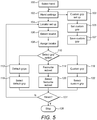
Figure 5 is a flow chart showing a procedure for setting up the system; -
Figure 6 is a flow chart showing operating procedures for the system when in first and second operating modes; and -
Figure 7 is a flow chart showing operating procedures for the system when in a third operating mode. -
Figure 1 schematically illustrates the components of a system for controlling a prosthetic hand having at least one motorised component. The motorised component(s) of the hand may be one or more digits, or a rotatable wrist component, for example. The system comprises afirst transceiver 10 and anelectronic controller 12 which is in two-way communication with thefirst transceiver 10. Thecontroller 12 is also in two-way communication with anelectric motor 14 which drives the motorised component when an appropriate signal is received from thecontroller 12. The system also comprises at least one second transceiver, referred to from now on as a locator, 16 which can wirelessly communicate with thefirst transceiver 10. The first andsecond transceivers - The system further comprises an
operator interface 18 which is in wireless communication with thefirst transceiver 10 and hence thecontroller 12. Theoperator interface 18 may be a personal computer running a control and set up program for the system, but is preferably a mobile communications device such as a smart phone or tablet which is running a mobile application through which the user sets up and controls the system. The operator interface preferably communicates with the first transceiver via Bluetooth. - Optionally, the system may also comprise one or
more input devices 20 which can communicate control signals to thecontroller 12 in response to inputs from the wearer of the hand. The input device(s) 20 may be switches which are actuated by known means such as residual digit movement or wrist movement. Alternatively or in addition, the input device(s) 20 may be pressure sensitive resistors or other sensors which derive signals from the electromyographic (EMG) activity of the wearer's residual muscle actions. - The hand uses a known drive arrangement in order to manipulate the motorised component(s). An example of one such arrangement which is suited to the purpose is that disclosed in the same applicant's earlier publication
WO2007/063266 . Further description of the specific drive arrangement will therefore not be provided here. -
Figure 2 illustrates the various components of the system when in operational use. Detailed description of the operational procedures employed by the system will be set out below, butFigure 2 shows aprosthetic hand 22 which comprises amotor 14 for each of the fourfinger digits 24 on the hand. Thehand 22 also has athumb digit 23 which has afirst motor 14 to pivot the thumb in the same manner as the fingers, and asecond motor 15 for rotational movement of the thumb. Also located on thehand 22 are thefirst transceiver 10 and thecontroller 12, and in the illustrated embodiment the controller is also connected to a pair ofinput devices 20 in the form of EMG sensors located upon the muscles in the wearer'sforearm 26. - The
hand 22 is mounted on a base 21 which is attached to the stump of theforearm 26. Thehand 22 may be provided with afirst wrist motor 27 which rotates the hand relative to the base 21, and/or asecond wrist motor 29 which pivots the hand relative to the base 21. Where present, the or eachwrist motor controller 12 so that thecontroller 12 can control themotor digit motors - A mobile communications device in the form of a smart phone provides the
operator interface 18. At least onelocator 16 is located upon asurface 28 so as to identify a given location to thefirst transceiver 10. In the illustrated embodiment offigure 2 there are a pair oflocators 16, which are intended to provide sequential and separate identification of their respective locations to the first transceiver. Further details on how the system employs the location information from the, or each, locator will be set out below. -
Figure 3 provides an example of how a plurality of locators may be placed in a space or room, in order to identify various locations. In the illustrated example, the room is a kitchen andlocators 16 have been located proximate atoaster 30, akettle 32 and the taps of thekitchen sink 34, as well as on the kitchen table 36 and a wall adjacent theentrance door 38 into the kitchen. As will be explained further below, the purpose of locatinglocators 16 at selected locations is that it allows the system to switch the components of the prosthetic hand of a wearer between various predetermined positions to form specific grips or the like for when the wearer wishes to turn on the taps or hold cutlery to eat a meal, for example. The wearer brings the hand, and first transceiver, within a predetermined distance of a locator with the result that the components of the hand take on a specific position related to that particular location, as identified by the locator. - Alternatively, or in addition, one or more of the
locators 16 located in the space may be provided in order to establish when the wearer has entered the space rather than to automatically instruct the hand to form a specific grip. For example, in the kitchen shown infigure 3 the locator by theentrance door 38 may be provided simply to inform the first transceiver and controller on the hand when the hand has entered the kitchen space. The benefit of this particular arrangement will be set out in more detail below. -
Figure 4 shows a further arrangement oflocators 16 which may be employed to determine when the wearer is in a given location. In this arrangement there are three locators provided, each on a different wall of an office space. By placing the threetransceivers 16 in this arrangement it is possible for the position of thefirst transceiver 10 andhand 22 to be triangulated as an alternative to the single locator located adjacent the door infigure 3 . -
Figure 5 shows a flow chart of how the system is initially set up using the operator interface. As described above, this is preferably done via a mobile application running on a smart phone or tablet but may alternatively be done via a program on a personal computer. The mobile application is launched in the smart phone or tablet and the user is then asked to select the prosthetic hand for which the set up is being performed atstep 100. Typically, this is done by the first transceiver located in the hand transmitting data to the smart phone and allowing the user to identify their prosthetic hand or hands. Once the hand is identified the settings menu for that hand is accessed atstep 102. Within the settings menu is a "locator set up" option which is then accessed atstep 104. At this point the second transceiver, otherwise known as the locator, is activated so that it may be detected by the smart phone atstep 106. Once detected, the detected locator is selected atstep 108 so that it may then be assigned an identifier code corresponding with a manipulation instruction for one or more of the motorised components of the hand to move into a given position or grip. - The assignation of the identifier code begins with the operator choosing a particular grip option at
step 110. In the illustrated example there are three grip options offered, but the invention is not limited to the specific options listed here. Instead, there may be at least one grip option provided atstep 110. From the three options in the illustrated example, the user can selected from a group of default grips and positions for the components viastep 112, a "favourite" subset of the default grips atstep 114, or a custom grip created and saved by the user atstep 116. - When saving a custom grip, the user accesses a custom grip set up 103 via the settings step 102. From the set up
step 103 the user selects astep 105 to set a custom grip. At this point the user manipulates the one or more components of the hand into a desired position using the normal manner in which they control the hand, such as via the control switches or sensors referred to above. The controller receives data back from the or each component motor regarding the run time it took for the motor to put the component in the position desired by the user. The controller then sends this data to the operator interface via the first transceiver so that the positional information may be saved atstep 107 in the application as a custom grip. Then, whenever the user wishes to assign a code relating to that saved custom grip to a locator they do so viastep 116 of the set up procedure. - Once the user has indicated which grip option they wish to access for the locator being set up, they then select a specific grip or grip subset via the respective selection steps 118,120,122. An identifier code for that specific grip or subset is then assigned and transmitted to the locator. Finally, the set up will ask the user at
step 124 if they have finished setting up locators with grip codes. If so, the set up program will terminate atstep 126. If not, it returns to locator set upstep 104. -
Figure 6 illustrates the procedural steps used by the system uses to control the hand when in the presence of the system shown in eitherfigure 2 orfigure 3 for example. After starting the process atstep 200 the process will check atstep 202 for a signal that the wearer of the hand is wanting to switch the system in a detection mode. In the detection mode the various locators which have been set up using the process shown infigure 5 will become visible to the first transceiver. There are a number of ways in which the wearer can activate the detection mode, but one example is to hold an EMG signal via a forearm muscle for a particular time period, say between 0.5 and 1.5 seconds. An alternative is to hold the hand in the open position for the same time period. When such a signal is detected atstep 202 the first transceiver will start actively searching atstep 204 for locators which are active and have been assigned a manipulation code, as described above. The first transceiver is typically set up to search for locators every 200-500ms. When the first transceiver detects a locator it signals the controller and atstep 206 the controller signals the motor of at least one motorised component to move the component into the position dictated by the saved manipulation instruction whose code has been assigned to the detected locator. The system is preferably set up so that the first transceiver detects a locator when it comes within 18cm of the locator. The process then terminates atstep 208 or may repeat. - The process of
figure 6 applies where one or more locators are present which have been assigned codes which relate to default grips or custom grips. One practical embodiment of this arrangement can be seen infigure 3 , which as described above shows a kitchen environment. Each of the locators, or locators, 16 positioned in the kitchen has been assigned a code which relates to a manipulation instruction and a default or custom grip which is desired at the point at which thelocator 16 is going to be placed. This may be a particular grip to hold and pour thekettle 32, which may be a different grip to that required to turn on a tap at thesink 34 or hold a knife or fork when eating at the kitchen table 36. Following the process shown infigure 6 , the hand wearer would enter the kitchen and then give the activation signal which instructs the first transceiver to start searching for active locators. This then means that whenever the wearer brings the hand and first transceiver within 18cm of a locator the grip whose code is assigned to that locator will be automatically formed by the hand under the instructions of the controller. - An alternative process is shown in
figure 7 which is for use where a locator has been assigned a code relating to a particular subset of grips rather than a specific grip. This process would therefore be used in the example described above where the kitchen offigure 3 has a single locator on the wall adjacent thedoor 38 rather than a number of locators around the room. As already described with respect tofigure 5 , when setting up this arrangement the locator is assigned a code which relates to a chosen subset of the default or custom grips, preferably 4-6 grips which are all likely to be required in a particular environment such as, for example, a kitchen, an office space or when driving in a vehicle. These subsets of grips would be accessed through a "favourites" menu in the mobile application or program. - This alternative process starts at
step 300 and its initial steps are identical to those of the process shown infigure 6 . Step 302 searches for an activation signal from the wearer of the hand, which is again preferably a held EMG signal lasting between 0.5 and 1.5 seconds. Once the activation signal is given the first transceiver begins looking for active locators atstep 304. As before the first transceiver is looking for a locator every 200 to 500ms, and will find a locator when it comes within around 18cm of it. When the locator is detected the first transceiver informs the controller and the controller then has access atstep 306 to only the 4-6 grips whose codes have been assigned to the detected locator. - Unlike with the previous process, the hand does not automatically form grips when employing this alternative process. Instead, the purpose of this process is to still give control of the hand to the wearer, but to reduce the number of grips available from perhaps 30 down to 4-6 which relate to the particular environment which the wearer has entered. Thus at
step 308, the process awaits one or more control signals from the wearer to then form atstep 310 one of the subset of grips which is selected based upon that signal or signals. The process then stops atstep 312 or may loop back to step 304 or 308 as desired. - A modification to the aforementioned process is to use the triangulation arrangement shown in
figure 4 to very accurately detect the location of the hand and wearer without the hand having to go within a predetermined distance of a locator. The difference being that atstep 304 the first transceiver would not be searching for a single locator but would be instead be communicating with all three locators in order to establish when the first transceiver has entered the location covered by the locators. Then the process would proceed to step 306 and access the grip subset as described above. - The present invention provides systems and processes for controlling a prosthetic hand having at least one motorised component, in which repeated muscle actions or movements of the wrist or residual digits by the wearer are not required to control the hand, or are at least very much reduced. Thus, the present invention reduces fatigue and discomfort for the hand wearer caused by frequently having to form grips or manipulate the hand. The present invention can be set up so that the hand automatically forms a given grip or position when placed at a certain location, or else the hand only has access to a small subset of grips when in that location. The former removes the need for the wearer to control the hand at all, whilst the latter significantly reduces the amount of actions or signals which need to be produced by the wearer.
- When in the set up process for assigning a manipulation code to a locator, when the locator to which the code is being assigned is detected the mobile application or program may indicate via the operator interface the remaining battery life of that locator.
- The triangulation system shown in
figure 4 will have at least three locators, or locators, but may have more than three. - The operation process shown in
figure 6 may have a safety step whereby the hand wearer must provide anactivation signal 202 before every grip change, rather than the preferred arrangement in which the grip will change as soon as the first transceiver comes within the predetermined distance of a locator. That way there are no unexpected grip changes of the hand if the wearer accidentally puts the hand within the predetermined distance of an alternative locator. However, this safety step is not essential and can be disabled. For example, a pair of locators may be placed either side of a wearer who works on an assembly or production line. Here one locator may be assigned a code to open the hand and release an item and the other assigned a code for closing the hand and picking up an item, for example. That way the grips will change automatically whenever the worker places the hand near the related locator without having to give the activation signal every time they wish the grip to change, which would not be practical in such an activity. - As seen in
figure 2 , a pair of locators may also be set up so that each is assigned a code which relates to one half of a desired hand manipulation. For example, a first locator could be assigned a code to rotate the wrist of a prosthetic hand as the hand passes the locator, and a second locator could be assigned a code for opening or closing the hand. In this way, the system could provide the hand with an automatic sequence of movements as the wearer sweeps the hand over the pair of locators. Such a set up could save time for the wearer is the desired actions are to be repeated numerous times. The system may employ more than two locators set up to provide a sequence of instruction codes to the first transceiver. - The "favourites" process illustrated in
figure 7 may include an additional step of indicating to the wearer that the hand is now operating in the favourites mode with the reduced subset of grips available. This indicator may be a brief twitch of all of the digits on the hand, an audible beep, or one or more flashes of an LED upon the locator. - Although the preferred distance at which the first transceiver will detect a locator is 18cm or less, it can be adjusted to suit individual situations and applications. For example, in the favourites mode it may be sufficient for the first and locators to come within 30cm of one another. Where Bluetooth is used for the wirelessly communicating first and locators, the predetermined activation distance can be adjusted as required via the mobile application or control program.
- The mobile application or program running the process and system may be set up so that the user can review what code is assigned to a given locator, in case the user has forgotten after the locator was set up.
- The locators may be set up so that they record data each time the first transceiver comes within the predetermined distance of the locator. That data may then be uploaded to the operator interface for analysis by an occupational therapist, for example.
- These and other modifications and improvements may be incorporated without departing from the scope of the present invention, as defined by the appended claims.
Claims (17)
- A method of controlling a prosthetic hand having at least one motorised component, the method comprising the steps of:providing the hand with a first wireless transceiver (10) and a controller (12) in communication with one another;providing an operator interface (18) in communication with the controller;storing on the operator interface at least one manipulation instruction relating to the at least one component;using the operator interface to assign a code to at least one second wireless transceiver (16), the code relating to the at least one manipulation instruction;placing the at least one second transceiver in a location at which the at least one manipulation instruction is to be given; andthe controller manipulating the at least one component in accordance with the at least one manipulation instruction when the first transceiver communicates to the controller that the at least one second transceiver is within a predetermined distance of the first transceiver.
- The method of claim 1, wherein the step of storing the at least one manipulation instruction comprises:the wearer of the hand sending one or more control signals to the controller to manipulate the at least one component into a desired position; andstoring the at least one manipulation instruction based upon the desired position of the component.
- The method of either preceding claim, wherein the manipulation of the at least one component in accordance with the manipulation instruction only takes place following an instruction signal sent from the wearer of the hand to the controller.
- The method of any preceding claim, wherein a plurality of manipulation instructions are stored and respective codes are assigned to a corresponding plurality of second transceivers, each of the second transceivers is placed at a location at which its assigned manipulation instruction is to be given, and the controller manipulates the at least one component in accordance with the manipulation instruction assigned to a particular second transceiver when that particular second transceiver is within the predetermined distance of the first transceiver.
- The method of any of claims 1 to 3, wherein a pair of sequential manipulation instructions are stored and a respective pair of codes are assigned to a pair of second transceivers, the pair of second transceivers are placed at locations at which the sequential manipulation instructions are to be given, and the controller manipulates the at least one component in accordance with a first manipulation instruction assigned to a first of the pair of second transceivers when that particular second transceiver is within the predetermined distance of the first transceiver, and the controller manipulates the at least one component in accordance with a second manipulation instruction assigned to a second of the pair of second transceivers when that particular second transceiver is within the predetermined distance of the first transceiver.
- The method of any preceding claim wherein the first and second transceivers are Bluetooth transceivers.
- The method of any preceding claim wherein the first transceiver searches for the at least one second transceiver at predetermined time intervals of between 200ms and 500ms.
- The method of any preceding claim wherein the predetermined distance between the first and second transceivers is less than or equal to 18cm.
- The method of any preceding claim, wherein:the step of storing on the operator interface at least one manipulation instruction comprises storing a plurality of manipulation instructions relating to the at least one component;the step of using the operator interface to assign a code to the at least one second wireless transceiver comprises assigning a code relating to a subset of the plurality of stored manipulation instructions to the at least second wireless transceiver;
andthe step of the controller manipulating the at least one component comprises the controller manipulating the at least one component in accordance with one of the subset of manipulation instructions when the first transceiver communicates to the controller that it is at the location, wherein the manipulation instruction executed by the controller is selected from the subset of instructions based upon a control signal from the wearer of the hand. - The method of claim 9 wherein there are three second transceivers which between them define the location, and the first transceiver communicates to the controller that is at the location when the position of the first transceiver is triangulated to the location by the second transceivers.
- A system for controlling a prosthetic hand having at least one motorised component, the system comprising:a first wireless transceiver (10) located on the hand;a controller (12) in communication with the first transceiver and the motorised component;an operator interface (18) having at least one manipulation instruction stored thereon, and being in communication with the controller; andat least one second wireless transceiver (16) which is assigned a code relating to the at least one manipulation instruction by the operator interface and is located in a location at which the at least one manipulation instruction is to be given;wherein the controller manipulates the at least one component in accordance with the at least one manipulation instruction when the first transceiver communicates to the controller that the at least one second transceiver is within a predetermined distance of the first transceiver.
- The system of claim 11, wherein the operator interface may store at least one manipulation instruction relating to a desired position of the component following the manipulation of the component into the desired position by the wearer of the hand.
- The system of claim 11 or claim 12, wherein the system comprises a plurality of second transceivers which are each assigned a code relating to a manipulation instruction by the operator interface and are each located in a location at which each respective manipulation instruction is to be given, and wherein the controller manipulates the at least one component in accordance with the manipulation instruction assigned to a particular second transceiver when that particular second transceiver is within the predetermined distance of the first transceiver.
- The system of any of claims 11 to 13 wherein the first and second transceivers are Bluetooth transceivers.
- The system of any of claims 11 to 14 wherein the predetermined distance between the first and second transceivers is less than or equal to 18cm.
- The system of any of claims 11 to 15 wherein there are three second transceivers which communicate with the operator interface such that the interface can triangulate the position of the first transceiver.
- The system of any of claims 11 to 16 wherein the operator interface is a mobile application provided upon a mobile communications device.
Applications Claiming Priority (2)
| Application Number | Priority Date | Filing Date | Title |
|---|---|---|---|
| GBGB1408253.1A GB201408253D0 (en) | 2014-05-09 | 2014-05-09 | Systems and methods for controlling a prosthetic hand |
| PCT/GB2015/051356 WO2015170112A1 (en) | 2014-05-09 | 2015-05-08 | Systems and methods for controlling a prosthetic hand |
Publications (2)
| Publication Number | Publication Date |
|---|---|
| EP3139868A1 EP3139868A1 (en) | 2017-03-15 |
| EP3139868B1 true EP3139868B1 (en) | 2019-04-17 |
Family
ID=51032515
Family Applications (1)
| Application Number | Title | Priority Date | Filing Date |
|---|---|---|---|
| EP15722749.7A Active EP3139868B1 (en) | 2014-05-09 | 2015-05-08 | Systems and methods for controlling a prosthetic hand |
Country Status (4)
| Country | Link |
|---|---|
| US (2) | US10265197B2 (en) |
| EP (1) | EP3139868B1 (en) |
| GB (1) | GB201408253D0 (en) |
| WO (1) | WO2015170112A1 (en) |
Families Citing this family (17)
| Publication number | Priority date | Publication date | Assignee | Title |
|---|---|---|---|---|
| GB201114264D0 (en) | 2011-08-18 | 2011-10-05 | Touch Emas Ltd | Improvements in or relating to prosthetics and orthotics |
| GB201302025D0 (en) | 2013-02-05 | 2013-03-20 | Touch Emas Ltd | Improvements in or relating to prosthetics |
| EP3102157B1 (en) | 2014-02-04 | 2019-04-17 | Rehabilitation Institute of Chicago | Modular and lightweight prosthesis components |
| GB201403265D0 (en) | 2014-02-25 | 2014-04-09 | Touch Emas Ltd | Prosthetic digit for use with touchscreen devices |
| GB201408253D0 (en) | 2014-05-09 | 2014-06-25 | Touch Emas Ltd | Systems and methods for controlling a prosthetic hand |
| GB201417541D0 (en) | 2014-10-03 | 2014-11-19 | Touch Bionics Ltd | Wrist device for a prosthetic limb |
| US10852835B2 (en) * | 2016-04-15 | 2020-12-01 | Board Of Regents, The University Of Texas System | Systems, apparatuses and methods for controlling prosthetic devices by gestures and other modalities |
| US20180014744A1 (en) * | 2016-07-13 | 2018-01-18 | Purdue Research Foundation | Motor-activated multi-functional wrist orthotic |
| EP3506857B1 (en) | 2016-09-02 | 2025-07-09 | Touch Bionics Limited | Systems and methods for prosthetic wrist rotation |
| US11185426B2 (en) | 2016-09-02 | 2021-11-30 | Touch Bionics Limited | Systems and methods for prosthetic wrist rotation |
| US10973660B2 (en) | 2017-12-15 | 2021-04-13 | Touch Bionics Limited | Powered prosthetic thumb |
| EP3576098A1 (en) * | 2018-05-30 | 2019-12-04 | Saphenus Medical Technology GmbH | Training device for the training stimulation of neural cell ends and corresponding prosthesis |
| US11547581B2 (en) | 2018-12-20 | 2023-01-10 | Touch Bionics Limited | Energy conservation of a motor-driven digit |
| US11931270B2 (en) | 2019-11-15 | 2024-03-19 | Touch Bionics Limited | Prosthetic digit actuator |
| US20230022882A1 (en) | 2019-12-19 | 2023-01-26 | Touch Bionics Limited | Electromyography and motion based control of upper limb prosthetics |
| US12115087B2 (en) | 2020-11-03 | 2024-10-15 | Touch Bionics Limited | Sensor for prosthetic control |
| US20230338170A1 (en) | 2022-04-25 | 2023-10-26 | Touch Bionics Limited | Sensor system and method for control of prosthetic devices |
Family Cites Families (243)
| Publication number | Priority date | Publication date | Assignee | Title |
|---|---|---|---|---|
| DE309367C (en) | ||||
| US1507682A (en) | 1924-03-17 | 1924-09-09 | Livingston Artificial Limb Com | Artificial limb |
| GB326970A (en) | 1929-02-26 | 1930-03-27 | Joseph Willie Levasseur | Improvements in artificial hands |
| US2477463A (en) | 1945-09-28 | 1949-07-26 | Otterman Joyce | Artificial arm |
| US2482555A (en) | 1946-01-01 | 1949-09-20 | Otterman Joyce | Artificial limb |
| GB607001A (en) | 1946-01-23 | 1948-08-24 | Arthur Appleby Moller | Improvements in artificial limbs |
| US2445711A (en) | 1946-06-17 | 1948-07-20 | Fitch And Sons Inc | Mechanical movement |
| US2516791A (en) | 1948-04-06 | 1950-07-25 | Northrop Aircraft Inc | Artificial arm |
| US2508156A (en) | 1948-05-20 | 1950-05-16 | Gillman Harry | Method of making artificial hands and replicas of other objects |
| US2592842A (en) | 1948-07-10 | 1952-04-15 | Samuel W Alderson | Shoulder harness for artificial arms |
| US2669727A (en) | 1951-07-24 | 1954-02-23 | Opuszenski Theodore | Artificial hand |
| US2983162A (en) | 1958-12-10 | 1961-05-09 | United Shoe Machinery Corp | Strain wave gearing-spring preloading |
| US3509583A (en) | 1965-09-09 | 1970-05-05 | Bendix Corp | Electro-mechanical hand having tactile sensing means |
| US3406584A (en) | 1967-08-21 | 1968-10-22 | Roantree Electro Mech Corp | Differential roller nut |
| US3683423A (en) | 1971-01-19 | 1972-08-15 | Russell S Crapanzano | Gravity activated prosthetic device |
| US3837010A (en) | 1972-03-16 | 1974-09-24 | Parke Davis & Co | Prosthetic elbow with resilient locking assembly |
| US3751995A (en) | 1972-06-02 | 1973-08-14 | Usm Corp | Sequential rotary and linear actuating mechanism |
| US3866246A (en) | 1972-11-14 | 1975-02-18 | Us Navy | Shoulder disarticulation prosthetic system |
| GB1386942A (en) | 1973-01-19 | 1975-03-12 | Steeper Roehampton Ltd Hugh | Artificial limbs |
| US3883900A (en) | 1973-09-07 | 1975-05-20 | Liberty Mutual Insurance Compa | Bioelectrically controlled prosthetic member |
| DE2434834C2 (en) | 1974-07-19 | 1985-07-25 | Werner Dr.-Ing. 2000 Hamburg Ohm | Gear motor |
| US3922930A (en) | 1974-12-23 | 1975-12-02 | Nasa | Remotely operable articulated manipulator |
| US4030141A (en) | 1976-02-09 | 1977-06-21 | The United States Of America As Represented By The Veterans Administration | Multi-function control system for an artificial upper-extremity prosthesis for above-elbow amputees |
| DE2607499C3 (en) | 1976-02-25 | 1982-04-08 | Messerschmitt-Bölkow-Blohm GmbH, 8000 München | Drive device for the fingers of an artificial hand |
| JPS5311456A (en) | 1976-07-15 | 1978-02-01 | Agency Of Ind Science & Technol | Thumb driving mechanism in artificial fingers |
| US4197592A (en) | 1976-09-17 | 1980-04-15 | Cluett, Peabody & Co., Inc. | Sport glove |
| FR2372255A1 (en) | 1976-11-30 | 1978-06-23 | Skf Cie Applic Mecanique | COUPLING DEVICE FOR DOUBLE TORSION TWIN-TORSION MACHINE WITH CONCURRING AXES |
| JPS6037227B2 (en) | 1977-01-25 | 1985-08-24 | 東芝シリコ−ン株式会社 | Method and device for manufacturing silicone-coated stretchable fabric products |
| GB1585256A (en) | 1977-07-01 | 1981-02-25 | Steeper Roehampton Ltd Hugh | Device for applying a controlled torque |
| GB2067074B (en) | 1979-12-21 | 1984-03-14 | Steeper Hugh Ltd | Silicon rubber covers for external prostheses |
| US4398110A (en) | 1982-05-05 | 1983-08-09 | Westinghouse Electric Corp. | Harmonic electric actuator |
| GB2146406B (en) | 1983-09-08 | 1986-09-17 | Univ Southampton | Actuator for converting rotary to oscillatory motion |
| US4558704A (en) | 1983-12-15 | 1985-12-17 | Wright State University | Hand control system |
| US4577127A (en) | 1983-12-21 | 1986-03-18 | Westinghouse Electric Corp. | Lightweight electric robotic actuator |
| US4813303A (en) | 1984-08-31 | 1989-03-21 | Mandreles, Inc. | Power drive speed reducer |
| US4623354A (en) | 1984-10-22 | 1986-11-18 | Northwestern University | Myoelectrically controlled artificial hand |
| US4678952A (en) | 1985-08-13 | 1987-07-07 | Intelledex Incorporated | Sealed joint for a robot and the like |
| SE451053B (en) | 1985-10-15 | 1987-08-31 | Centri Gummifabrik Ab | Hand prosthesis |
| US4973215A (en) | 1986-02-18 | 1990-11-27 | Robotics Research Corporation | Industrial robot with servo |
| US4822238A (en) | 1986-06-19 | 1989-04-18 | Westinghouse Electric Corp. | Robotic arm |
| GB8616985D0 (en) | 1986-07-11 | 1986-08-20 | Steeper Hugh Ltd | Plasticized material |
| ATE88357T1 (en) | 1987-04-21 | 1993-05-15 | Smith & Nephew | GLOVE. |
| US4960425A (en) | 1987-05-27 | 1990-10-02 | Mentor Corporation | Textured surface frosthesis implants |
| US4808187A (en) | 1987-10-05 | 1989-02-28 | Iowa State University Research Foundation, Inc. | Tactile stimulus receptor for a hand prosthesis |
| US4990162A (en) | 1988-03-21 | 1991-02-05 | Children's Hospital At Stanford | Rotary hand prosthesis |
| BE1001559A5 (en) | 1988-04-01 | 1989-12-05 | Baxter Int | GLOVE. |
| US6175962B1 (en) | 1988-10-17 | 2001-01-23 | Gary Karlin Michelson | Surgical glove |
| US5062673A (en) | 1988-12-28 | 1991-11-05 | Kabushiki Kaisha Toyota Chuo Kenkyusho | Articulated hand |
| US5252102A (en) | 1989-01-24 | 1993-10-12 | Electrobionics Corporation | Electronic range of motion apparatus, for orthosis, prosthesis, and CPM machine |
| US4955918A (en) | 1989-05-30 | 1990-09-11 | University Of Southern California | Artificial dexterous hand |
| US5355063A (en) | 1990-11-01 | 1994-10-11 | Westinghouse Electric Corp. | Robotic system for servicing the heat exchanger tubes of a nuclear steam generator |
| US5133775A (en) | 1991-04-29 | 1992-07-28 | Sen Jung Chen | Covering device for an artificial limb |
| US5133776A (en) | 1991-12-11 | 1992-07-28 | Crowder Dan M | Prosthetic volume compensation device |
| US5387245A (en) | 1991-12-23 | 1995-02-07 | Fay; John N. | Inflatable prosthesis liner |
| US5246463A (en) | 1992-02-21 | 1993-09-21 | Giampapa Vincent C | Sensate and spacially responsive prosthesis |
| US5413611A (en) | 1992-07-21 | 1995-05-09 | Mcp Services, Inc. | Computerized electronic prosthesis apparatus and method |
| US5498472A (en) | 1993-06-22 | 1996-03-12 | Kombi Ltd. | Non-laminated differential wind barrier fabrics and garments |
| JPH07174631A (en) | 1993-12-16 | 1995-07-14 | Kao Corp | Skin colorimetric method and spectral reflectance spectrum estimation method |
| GB9404830D0 (en) | 1994-03-12 | 1994-04-27 | Lothian Health Board | Hand prosthesis |
| WO1996023643A1 (en) | 1995-02-02 | 1996-08-08 | Baxter International Inc. | A process for making a glove having a polyurethane coating |
| US5852675A (en) | 1995-04-14 | 1998-12-22 | Kiyoshi Matsuo | Color chart for image correction and method of color correction |
| US5851194A (en) | 1995-07-17 | 1998-12-22 | Fratrick; Richard A. | Quick release mechanism for orthopedic limb brace |
| US6254385B1 (en) | 1997-01-02 | 2001-07-03 | Lj Laboratories, Llc | Apparatus and method for measuring optical characteristics of teeth |
| US5785960A (en) | 1997-03-19 | 1998-07-28 | Elizabeth Arden Co., Division Of Conopco, Inc. | Method and system for customizing dermatological foundation products |
| SE512643C2 (en) | 1997-04-29 | 2000-04-17 | Handevelop Ab | Apparatus for artificial sensation by recording touch sounds |
| US6111973A (en) | 1997-05-29 | 2000-08-29 | Holt; Kenneth Dale | Method for producing color-comparable photographs with fleshtone color selections for prosthetic fabrication |
| US5888213A (en) | 1997-06-06 | 1999-03-30 | Motion Control, Inc. | Method and apparatus for controlling an externally powered prosthesis |
| DE19725414A1 (en) | 1997-06-17 | 1998-12-24 | Bosch Gmbh Robert | Electromotive actuator for use in technical facilities, especially in motor vehicles |
| GB9722403D0 (en) | 1997-10-24 | 1997-12-24 | Royal Infirmary Of Edinburgh N | Upper limb prosthesis |
| US6177034B1 (en) | 1998-04-03 | 2001-01-23 | A-Pear Biometric Replications Inc. | Methods for making prosthetic surfaces |
| DE29811426U1 (en) | 1998-06-29 | 1998-09-03 | Otto Bock Orthopädische Industrie Besitz- und Verwaltungs-Kommanditgesellschaft, 37115 Duderstadt | Cosmetic stocking |
| US6249348B1 (en) | 1998-11-23 | 2001-06-19 | Lj Laboratories, L.L.C. | Integrated spectrometer assembly and methods |
| US6244873B1 (en) | 1998-10-16 | 2001-06-12 | At&T Corp. | Wireless myoelectric control apparatus and methods |
| US6347408B1 (en) | 1998-11-05 | 2002-02-19 | Allegiance Corporation | Powder-free gloves having a coating containing cross-linked polyurethane and silicone and method of making the same |
| DE19854762C2 (en) | 1998-11-27 | 2002-07-18 | Marc Franke | Artificial hand |
| US6344062B1 (en) | 1999-03-18 | 2002-02-05 | The State University Rutgers | Biomimetic controller for a multi-finger prosthesis |
| DE60010789T2 (en) | 1999-03-22 | 2004-10-07 | Advanced Control Res Ltd | limbs prostheses |
| FR2792865B1 (en) | 1999-04-27 | 2001-06-15 | Cie Generale De Participations | DEVICE FOR REMOTE CONTROL OF MOTION, IN PARTICULAR OF GRIPPING MEMBERS |
| AU5146200A (en) | 1999-05-19 | 2000-12-05 | Rutgers, The State University Of New Jersey | Dexterous prosthetic hand |
| US6437866B1 (en) | 1999-07-07 | 2002-08-20 | Fd Management, Inc. | System for assisting customers in selecting an optimum color cosmetic product |
| JP3218327B2 (en) | 1999-09-09 | 2001-10-15 | 東京大学長 | Angle detection sensor |
| GB2357725A (en) | 1999-12-02 | 2001-07-04 | Blatchford & Sons Ltd | Silicone cosmesis |
| JP4421071B2 (en) | 2000-04-21 | 2010-02-24 | 株式会社資生堂 | Makeup counseling device |
| AU2001261160A1 (en) | 2000-05-03 | 2001-11-12 | Stephen T Flock | Prosthesis and method of making |
| JP2002131135A (en) | 2000-10-20 | 2002-05-09 | Kao Corp | Reference color chart and makeup simulation device |
| WO2002049534A2 (en) | 2000-12-19 | 2002-06-27 | Alorman Advanced Medical Technologies, Ltd. | Method for controlling multi-function myoelectric prothesis |
| US6660042B1 (en) | 2001-02-02 | 2003-12-09 | Rutgers, The State University Of New Jersey | Methods of biomimetic finger control by filtering of distributed forelimib pressures |
| JP2004518096A (en) | 2001-02-08 | 2004-06-17 | エクスラー アクチエンゲゼルシャフト | Wave transmission having a cap-shaped output ring |
| DE10105814C1 (en) | 2001-10-20 | 2002-09-12 | Oechsler Ag | Harmonic drive comprises a housing-independent support ring mounted on the front side of a base plate and enclosed by a housing cover |
| JP2002243000A (en) | 2001-02-19 | 2002-08-28 | Harmonic Drive Syst Ind Co Ltd | Actuator with wave gear reducer |
| KR100888192B1 (en) | 2001-03-22 | 2009-03-12 | 비숍 이노베이션 리미티드 | Method and apparatus for the production of forged racks |
| JP2002310242A (en) | 2001-04-17 | 2002-10-23 | Murakami Corp | Bearing structure of worm gear |
| US6684754B2 (en) | 2001-07-10 | 2004-02-03 | Alan Elbert Comer | Pneumatic muscle analogs for exoskeletal robotic limbs and associated control mechanisms |
| GB0117383D0 (en) | 2001-07-17 | 2001-09-05 | Steeper Hugh Ltd | A gripper device |
| SE0102831D0 (en) | 2001-08-27 | 2001-08-27 | Bergomed Ab | Device for a hand prosthesis |
| SE0102834D0 (en) | 2001-08-27 | 2001-08-27 | Bergomed Ab | Device for a finger prosthesis |
| SE0102836L (en) | 2001-08-27 | 2003-02-28 | Bergomed Ab | Mechanical hand with the grasping ability of the human hand |
| SE0102835D0 (en) | 2001-08-27 | 2001-08-27 | Bergomed Ab | Thumb at mechanical hand |
| SE0102833D0 (en) | 2001-08-27 | 2001-08-27 | Bergomed Ab | Drive device at a finger prosthesis |
| JP4121262B2 (en) | 2001-10-02 | 2008-07-23 | カヤバ工業株式会社 | Manufacturing method of power transmission device and manufacturing method of electric power steering device |
| JP2003134526A (en) | 2001-10-19 | 2003-05-09 | Univ Waseda | Color reproduction device and color reproduction method |
| SG103371A1 (en) | 2001-12-28 | 2004-04-29 | Matsushita Electric Works Ltd | Wearable human motion applicator |
| US20040078299A1 (en) | 2002-01-31 | 2004-04-22 | Kathleen Down-Logan | Portable color and style analysis, match and management system |
| JP3893453B2 (en) | 2002-04-16 | 2007-03-14 | 独立行政法人産業技術総合研究所 | Prosthetic hand |
| US6824523B2 (en) | 2002-06-28 | 2004-11-30 | Tamarack Habilitation Technologies, Inc. | Adjustable mounting housing for orthotic ankle flexure joint |
| US7144430B2 (en) | 2002-07-12 | 2006-12-05 | Motion Control, Inc. | Wrist device for use with a prosthetic limb |
| JP2004073802A (en) | 2002-08-20 | 2004-03-11 | Forest Denki Kk | Multipurpose measuring unit for skin |
| US7736394B2 (en) | 2002-08-22 | 2010-06-15 | Victhom Human Bionics Inc. | Actuated prosthesis for amputees |
| CA2500005C (en) | 2002-09-26 | 2011-12-06 | Barrett Technology, Inc. | Intelligent, self-contained robotic hand |
| WO2004059249A1 (en) | 2002-12-30 | 2004-07-15 | Fabio Salsedo | Goniometric sensor |
| JP2004224280A (en) | 2003-01-24 | 2004-08-12 | Koyo Seiko Co Ltd | Electric power steering device |
| WO2004094870A1 (en) | 2003-04-24 | 2004-11-04 | Toyota Jidosha Kabushiki Kaisha | Planetary differential screw-type rotational motion/linear motion converter |
| DE20315575U1 (en) | 2003-10-10 | 2004-01-15 | medi Bayreuth Weihermüller & Voigtmann GmbH & Co. KG | Liner or knee cap for stumps of amputated arms or legs comprises sleeve of flexible silicone, polyurethane or thermoplastic elastomer with outer coating of polymer which assists sliding |
| US7394488B2 (en) | 2003-10-30 | 2008-07-01 | Hewlett-Packard Development Company, L.P. | System and method for dual white balance compensation of images |
| US20050101693A1 (en) | 2003-11-06 | 2005-05-12 | Ohio Willow Wood Company | Gel and cushioning devices |
| US7370896B2 (en) | 2003-12-30 | 2008-05-13 | Strider Labs, Inc. | Robotic hand with extendable palm |
| WO2005071372A1 (en) | 2004-01-23 | 2005-08-04 | Olympus Corporation | Image processing system and camera |
| CA2556041C (en) | 2004-02-12 | 2015-04-21 | Ossur Hf | System and method for motion-controlled foot unit |
| US7316795B1 (en) | 2004-03-02 | 2008-01-08 | Stefan Johannes Knauss | Method for overmolding a painted silicone rubber human extremity prosthesis |
| US20060029909A1 (en) | 2004-08-05 | 2006-02-09 | Kaczkowski Michael D | Method and apparatus for producing objective color references for color matching or identifying |
| EP1812968B1 (en) | 2004-08-25 | 2019-01-16 | Callahan Cellular L.L.C. | Apparatus for multiple camera devices and method of operating same |
| US7640680B1 (en) | 2004-09-20 | 2010-01-05 | Castro Ernesto G | Pedorthic systems |
| US7803438B2 (en) | 2004-09-30 | 2010-09-28 | Ansell Healthcare Products Llc | Polymeric shell adherently supported by a liner and a method of manufacture |
| WO2006058190A2 (en) | 2004-11-23 | 2006-06-01 | Color Savvy Systems Limited | Method for deriving consistent, repeatable color measurements from data provided by a digital imaging device |
| JP2006159320A (en) | 2004-12-03 | 2006-06-22 | Sharp Corp | Robot hand |
| CA2592042C (en) | 2004-12-22 | 2014-12-16 | Oessur Hf | Systems and methods for processing limb motion |
| US20060189899A1 (en) | 2005-01-10 | 2006-08-24 | Flaherty J Christopher | Joint movement apparatus |
| US7881780B2 (en) | 2005-01-18 | 2011-02-01 | Braingate Co., Llc | Biological interface system with thresholded configuration |
| US20070016265A1 (en) | 2005-02-09 | 2007-01-18 | Alfred E. Mann Institute For Biomedical Engineering At The University Of S. California | Method and system for training adaptive control of limb movement |
| GB0504279D0 (en) | 2005-03-02 | 2005-04-06 | Carroll Charles C | Skin colour matching system and method |
| US20060212129A1 (en) | 2005-03-16 | 2006-09-21 | Lake Joseph C | Partial hand prosthesis |
| WO2006106509A2 (en) | 2005-04-04 | 2006-10-12 | Hadasit Ltd. | Medical imaging method and system |
| WO2006110790A2 (en) | 2005-04-12 | 2006-10-19 | Rehabilitation Institute Of Chicago | Method for creating covers for prosthetic devices and other dynamic supporting members |
| US7316304B2 (en) | 2005-06-10 | 2008-01-08 | Warn Industries, Inc. | Four-wheel drive center disconnect electric actuator |
| WO2006138388A2 (en) | 2005-06-17 | 2006-12-28 | Ada Technologies, Inc. | Cable lock device for prosthetic and orthotic devices |
| US7522768B2 (en) | 2005-09-09 | 2009-04-21 | Hewlett-Packard Development Company, L.P. | Capture and systematic use of expert color analysis |
| US7522769B2 (en) | 2005-09-09 | 2009-04-21 | Hewlett-Packard Development Company, L.P. | Method and system for skin color estimation from an image |
| DE112006002718T5 (en) | 2005-10-11 | 2008-08-21 | Matsushita Electric Industrial Co., Ltd., Kadoma | Movement assisting device and movement assisting method |
| GB0524284D0 (en) | 2005-11-29 | 2006-01-04 | Touch Emas Ltd | Prosthesis |
| DE102005061313A1 (en) | 2005-12-20 | 2007-08-16 | Otto Bock Healthcare Ip Gmbh & Co. Kg | hand prosthesis |
| DE102005061266A1 (en) | 2005-12-20 | 2007-08-16 | Otto Bock Healthcare Ip Gmbh & Co. Kg | Hand prosthesis and power transmission device |
| DE102005061312A1 (en) | 2005-12-20 | 2007-08-16 | Otto Bock Healthcare Ip Gmbh & Co. Kg | hand prosthesis |
| DE102005062083A1 (en) | 2005-12-22 | 2007-07-05 | Otto Bock Healthcare Ip Gmbh & Co. Kg | Artificial hand, comprises elastic element and unit for being locked in required position |
| DE102006006966A1 (en) | 2005-12-23 | 2007-08-16 | Otto Bock Healthcare Ip Gmbh & Co. Kg | Clutch for prostheses |
| JP4614879B2 (en) | 2005-12-28 | 2011-01-19 | 株式会社ハーモニック・ドライブ・システムズ | Sealed worm gear type finger joint unit |
| CN100336639C (en) | 2006-01-20 | 2007-09-12 | 哈尔滨工业大学 | Thumb mechanism of underactuated self-adaptive hand prosthesis |
| US7658119B2 (en) | 2006-03-28 | 2010-02-09 | University Of Southern California | Biomimetic tactile sensor |
| JP5005944B2 (en) | 2006-04-03 | 2012-08-22 | 株式会社Pfu | Color reproduction system |
| US8298293B2 (en) | 2006-04-28 | 2012-10-30 | College Park Industries, Inc. | Prosthetic sensing systems and methods |
| DE102006020777B4 (en) | 2006-05-03 | 2010-08-12 | Otto Bock Healthcare Gmbh | Artificial joint |
| US8016893B2 (en) | 2006-06-21 | 2011-09-13 | The United States Of America As Represented By The Administrator Of The National Aeronautics And Space Administration | Gear bearing drive |
| US7837640B2 (en) | 2006-07-21 | 2010-11-23 | Simbex Llc | Dynamic body protector |
| GB0616162D0 (en) | 2006-08-15 | 2006-09-20 | Whiteley Graham | Compact rotary actuator |
| US8437844B2 (en) | 2006-08-21 | 2013-05-07 | Holland Bloorview Kids Rehabilitation Hospital | Method, system and apparatus for real-time classification of muscle signals from self-selected intentional movements |
| US10758394B2 (en) | 2006-09-19 | 2020-09-01 | Myomo, Inc. | Powered orthotic device and method of using same |
| GB0620250D0 (en) | 2006-10-12 | 2006-11-22 | Touch Emas Ltd | Process for forming coverings |
| JP2010505578A (en) | 2006-10-13 | 2010-02-25 | コーニンクレッカ フィリップス エレクトロニクス エヌ ヴィ | Switchable joint restraint system |
| DE102007005858A1 (en) | 2007-02-01 | 2008-08-14 | Otto Bock Healthcare Products Gmbh | prosthetic finger |
| US9114030B2 (en) | 2007-02-06 | 2015-08-25 | Deka Products Limited Partnership | System for control of a prosthetic device |
| US8449624B2 (en) | 2007-02-06 | 2013-05-28 | Deka Products Limited Partnership | Arm prosthetic device |
| WO2008098059A2 (en) | 2007-02-06 | 2008-08-14 | Deka Integrated Solutions Corp. | Method and apparatus for control of a prosthetic |
| US8979943B2 (en) | 2007-02-06 | 2015-03-17 | Deka Products Limited Partnership | Arm prosthetic device |
| US8864845B2 (en) | 2007-02-06 | 2014-10-21 | DEKA Limited Partnership | System for control of a prosthetic device |
| CA2676672C (en) | 2007-02-06 | 2015-06-16 | Hanger Orthopedic Group Inc. | System and method for using a digit to position a prosthetic or orthotic device |
| WO2009011682A1 (en) | 2007-07-19 | 2009-01-22 | Northeastern University | Gear bearing drive |
| WO2009092868A1 (en) | 2008-01-23 | 2009-07-30 | Ijina | Device and method for the space-colorimetric measurement of a three-dimensional object |
| GB0804933D0 (en) | 2008-03-17 | 2008-04-16 | Touch Emas Ltd | Covering |
| US9180025B2 (en) | 2008-04-21 | 2015-11-10 | Vanderbilt University | Powered leg prosthesis and control methodologies for obtaining near normal gait |
| US7922773B1 (en) | 2008-05-16 | 2011-04-12 | Rehabilitation Institute Of Chicago | Method and apparatus for prosthetic limb rotation control |
| US20100016990A1 (en) | 2008-07-21 | 2010-01-21 | Kulite Semiconductor Products, Inc. | Microelectromechanical system (MEMS) employing wireless transmission for providing sensory signals |
| WO2010018358A2 (en) | 2008-08-11 | 2010-02-18 | Rslsteeper Group Limited | A device resembling a part of the human body which is able to be actuated |
| DE102008056520B4 (en) | 2008-11-08 | 2017-10-19 | Stefan Schulz | finger member |
| KR20100053005A (en) | 2008-11-12 | 2010-05-20 | 삼성전자주식회사 | Electricity connecting device of joint unit and robot having the same |
| US8299899B2 (en) * | 2008-11-19 | 2012-10-30 | Greatbatch Ltd. | AIMD external programmer incorporating a multifunction RFID reader having a limited transmit time and a time-out period |
| GB0823228D0 (en) | 2008-12-19 | 2009-01-28 | Touch Emas Ltd | Prosthesis covering |
| AT508205B1 (en) | 2009-01-22 | 2011-08-15 | Puchhammer Gregor Dr | ORBITAL TRANSMISSION |
| EP2419057B1 (en) | 2009-04-13 | 2014-10-01 | DEKA Products Limited Partnership | System and apparatus for orientation control |
| US8593255B2 (en) * | 2009-04-24 | 2013-11-26 | Nokia Corporation | Method and apparatus for providing user interaction via transponders |
| GB0910920D0 (en) | 2009-06-24 | 2009-08-05 | Touch Emas Ltd | Method of controlling a prosthesis |
| WO2011001136A2 (en) | 2009-07-02 | 2011-01-06 | Rslsteeper Group Limited | Prosthetic apparatus |
| US9265625B2 (en) | 2009-08-20 | 2016-02-23 | Vanderbilt University | Jointed mechanical devices |
| EP2467101B1 (en) | 2009-08-20 | 2016-04-06 | Vanderbilt University | Control system for jointed mechanical devices |
| EP2480173B1 (en) | 2009-09-22 | 2016-11-23 | Memic Innovative Surgery Ltd. | Mechanical finger |
| GB0916895D0 (en) * | 2009-09-25 | 2009-11-11 | Touch Emas Ltd | Prosthetic apparatus and method |
| FR2951514B1 (en) | 2009-10-16 | 2012-03-30 | Thales Sa | DIFFERENTIAL ROLLER SCREW |
| US8425620B2 (en) | 2009-12-08 | 2013-04-23 | Hdt Engineering Services, Inc. | Modular limb segment connector |
| GB0922603D0 (en) | 2009-12-24 | 2010-02-10 | Touch Emas Ltd | Skin colour determining apparatus and method |
| DE102010005690B4 (en) | 2010-01-25 | 2012-04-19 | Otto Bock Healthcare Products Gmbh | Adjusting device for a prosthetic device and method for operating such an adjusting device |
| US8662552B2 (en) | 2010-02-23 | 2014-03-04 | Massachusetts Institute Of Technology | Dexterous and compliant robotic finger |
| GB201003573D0 (en) | 2010-03-04 | 2010-04-21 | Touch Emas Ltd | Hand prothesis |
| JP5467267B2 (en) | 2010-03-05 | 2014-04-09 | 国立大学法人大阪大学 | DEVICE CONTROL DEVICE, DEVICE SYSTEM, DEVICE CONTROL METHOD, DEVICE CONTROL PROGRAM, AND RECORDING MEDIUM |
| US20120061155A1 (en) | 2010-04-09 | 2012-03-15 | Willow Garage, Inc. | Humanoid robotics system and methods |
| CN102233585A (en) | 2010-04-29 | 2011-11-09 | 鸿富锦精密工业(深圳)有限公司 | Arm member of robot |
| US9068666B2 (en) | 2010-05-10 | 2015-06-30 | Borgwarner Inc. | Electronic coolant valve with integral actuator mechanism |
| US20110278061A1 (en) | 2010-05-13 | 2011-11-17 | Farnan Brian P | System to enable gloved hands to interact with electronic touchscreen devices |
| US8571281B2 (en) | 2010-07-13 | 2013-10-29 | Carestream Health, Inc. | Dental shade mapping |
| US8337568B2 (en) | 2010-07-14 | 2012-12-25 | Charles Colin Macduff | Mechanical prosthetic finger device |
| US9034055B2 (en) | 2010-09-29 | 2015-05-19 | University Of Pittsburgh-Of The Commonwealth System Of Higher Education | Human-machine interface based on task-specific temporal postural synergies |
| US8634640B2 (en) | 2010-10-21 | 2014-01-21 | Hewlett-Packard Development Company, L.P. | Method and apparatus for selecting a color palette |
| US9174339B2 (en) | 2010-11-22 | 2015-11-03 | Vanderbilt University | Control system for a grasping device |
| US20120280812A1 (en) * | 2011-05-04 | 2012-11-08 | General Electric Company | Rfid based guidance in remote locations |
| US9321172B2 (en) | 2011-05-13 | 2016-04-26 | Hdt Expeditionary Systems, Inc. | Modular rotational electric actuator |
| US9931230B2 (en) | 2011-08-01 | 2018-04-03 | George Mason University | Artificial body part control system using ultrasonic imaging |
| DE102011110101A1 (en) | 2011-08-13 | 2013-02-14 | Stefan Schulz | Method for moving and holding a phalanx |
| GB201114264D0 (en) | 2011-08-18 | 2011-10-05 | Touch Emas Ltd | Improvements in or relating to prosthetics and orthotics |
| GB201116060D0 (en) | 2011-09-16 | 2011-11-02 | Touch Emas Ltd | Method of controlling a prosthesis |
| GB201116069D0 (en) | 2011-09-16 | 2011-11-02 | Touch Emas Ltd | Method and apparatus for controlling a prosthetic device |
| US8605049B2 (en) | 2011-09-28 | 2013-12-10 | Jennifer Spencer | Bulk resistive glove |
| US20130144197A1 (en) | 2011-12-06 | 2013-06-06 | Ossur Hf | Orthopedic device for dynamically treating osteoarthritis |
| GB201200167D0 (en) | 2012-01-05 | 2012-02-15 | Rsl Steeper Group Ltd | An artificial hand component |
| US20130268094A1 (en) | 2012-04-10 | 2013-10-10 | Ford Global Technologies, Llc | Add-on capacitive touchscreen aid |
| DE102012009699A1 (en) | 2012-05-15 | 2013-11-21 | Pohlig Gmbh | Prosthesis or denture cover |
| GB201213030D0 (en) | 2012-07-23 | 2012-09-05 | Touch Emas Ltd | Improvements in or relating to prosthetics and orthotics |
| US10318863B2 (en) | 2012-07-24 | 2019-06-11 | Rehabilitation Institute Of Chicago | Systems and methods for autoconfiguration of pattern-recognition controlled myoelectric prostheses |
| KR101465020B1 (en) * | 2012-12-20 | 2014-11-27 | 한국과학기술연구원 | Apparatus for controlling artificial hand |
| ITPI20130004A1 (en) | 2013-01-16 | 2014-07-17 | Machinale S R L Fab | PROSTHETIC STRUCTURE FOR HAND AMPUTATION |
| GB201302025D0 (en) | 2013-02-05 | 2013-03-20 | Touch Emas Ltd | Improvements in or relating to prosthetics |
| ES2661538T3 (en) | 2013-06-12 | 2018-04-02 | Otto Bock Healthcare Gmbh | Limb device control |
| US20150142082A1 (en) | 2013-11-15 | 2015-05-21 | ElectroCore, LLC | Systems and methods of biofeedback using nerve stimulation |
| EP3102157B1 (en) | 2014-02-04 | 2019-04-17 | Rehabilitation Institute of Chicago | Modular and lightweight prosthesis components |
| GB201403265D0 (en) | 2014-02-25 | 2014-04-09 | Touch Emas Ltd | Prosthetic digit for use with touchscreen devices |
| GB201408253D0 (en) | 2014-05-09 | 2014-06-25 | Touch Emas Ltd | Systems and methods for controlling a prosthetic hand |
| GB201417541D0 (en) | 2014-10-03 | 2014-11-19 | Touch Bionics Ltd | Wrist device for a prosthetic limb |
| CA2910392A1 (en) | 2014-10-31 | 2016-04-30 | Marin Renner Schultz | Breath and head tilt controlled prosthetic limb |
| US10314725B2 (en) | 2014-11-13 | 2019-06-11 | The Regents Of The University Of Michigan | Method for amplifying signals from individual nerve fascicles |
| US9720515B2 (en) | 2015-01-02 | 2017-08-01 | Wearable Devices Ltd. | Method and apparatus for a gesture controlled interface for wearable devices |
| EP3106133B1 (en) | 2015-06-19 | 2018-01-31 | Georg-August-Universität Göttingen Stiftung Öffentlichen Rechts Universitätsmedizin | Powered, multi-functional limb movement auxiliary device, particularly prosthesis and movement-assisting orthosis, with combined estimation regimes |
| US10219919B2 (en) | 2015-08-18 | 2019-03-05 | Yale University | Multi-grasp prosthetic hand |
| WO2017069456A1 (en) | 2015-10-19 | 2017-04-27 | 한양대학교에리카산학협력단 | Object-shape-adaptive prosthetic robot finger |
| US10292839B2 (en) | 2016-01-21 | 2019-05-21 | Invisible Hand Enterprises, Llc | Gripping device with switchable prehension modes |
| ITUB20160595A1 (en) | 2016-02-09 | 2017-08-09 | Univ Degli Studi Di Siena | ROBOTIC PRELIMINARY ELEMENT WEARABLE FROM A SUBJECT FOR ASSISTANCE TO THE OUTLET |
| US10758379B2 (en) | 2016-05-25 | 2020-09-01 | Scott MANDELBAUM | Systems and methods for fine motor control of fingers on a prosthetic hand to emulate a natural stroke |
| US20180014744A1 (en) | 2016-07-13 | 2018-01-18 | Purdue Research Foundation | Motor-activated multi-functional wrist orthotic |
| US11185426B2 (en) | 2016-09-02 | 2021-11-30 | Touch Bionics Limited | Systems and methods for prosthetic wrist rotation |
| EP3506857B1 (en) | 2016-09-02 | 2025-07-09 | Touch Bionics Limited | Systems and methods for prosthetic wrist rotation |
| CH712952A1 (en) | 2016-09-26 | 2018-03-29 | Appsocial Org Stiftung | Power-operated prosthesis. |
| US10376389B2 (en) | 2016-11-01 | 2019-08-13 | Glenn Gaston | Myoelectric prosthesis and method |
| US11026816B2 (en) | 2017-01-12 | 2021-06-08 | Deka Products Limited Partnership | Prosthetic device |
| US20180221177A1 (en) | 2017-02-03 | 2018-08-09 | David Kaltenbach | Digital interface system and method |
| US20180256365A1 (en) | 2017-03-13 | 2018-09-13 | Edward J. McCarron | Stimulus Transmission and Remote Sensing System |
| ES1187509Y (en) | 2017-03-31 | 2017-10-03 | Centro Ortopedico Tecnologico S L U | Microelectric prosthesis |
| WO2018218129A1 (en) | 2017-05-25 | 2018-11-29 | Vanderbilt University | Upper extremity assistance device |
| US11547581B2 (en) | 2018-12-20 | 2023-01-10 | Touch Bionics Limited | Energy conservation of a motor-driven digit |
-
2014
- 2014-05-09 GB GBGB1408253.1A patent/GB201408253D0/en not_active Ceased
-
2015
- 2015-05-08 EP EP15722749.7A patent/EP3139868B1/en active Active
- 2015-05-08 US US15/307,385 patent/US10265197B2/en active Active
- 2015-05-08 WO PCT/GB2015/051356 patent/WO2015170112A1/en not_active Ceased
-
2019
- 2019-01-16 US US16/249,696 patent/US11234842B2/en active Active
Non-Patent Citations (1)
| Title |
|---|
| None * |
Also Published As
| Publication number | Publication date |
|---|---|
| US20190216618A1 (en) | 2019-07-18 |
| WO2015170112A1 (en) | 2015-11-12 |
| GB201408253D0 (en) | 2014-06-25 |
| EP3139868A1 (en) | 2017-03-15 |
| US11234842B2 (en) | 2022-02-01 |
| US20170049586A1 (en) | 2017-02-23 |
| US10265197B2 (en) | 2019-04-23 |
Similar Documents
| Publication | Publication Date | Title |
|---|---|---|
| US11234842B2 (en) | Systems and methods for controlling a prosthetic hand | |
| US11198060B2 (en) | Control apparatus and control program | |
| CN109313493B (en) | Apparatus for controlling computer based on hand movement and position | |
| EP3037946B1 (en) | Remote controller, information processing method and system | |
| US10123631B2 (en) | Operating system for, and a method of, operating an article of furniture | |
| CN117897678A (en) | Multi-device gesture control | |
| EP3293989A3 (en) | Methods for provisioning a wireless beacon | |
| ES2817424T3 (en) | Procedure and device for the operation of a domestic appliance and domestic appliance | |
| US20180067562A1 (en) | Display system operable in a non-contact manner | |
| JP2019533237A5 (en) | ||
| KR20200063353A (en) | Multi-functional Electronic Prosthetic Hand using cameras and artificial intelligence | |
| EP3059691A1 (en) | Method and system to trigger actions based on motion monitoring | |
| US12127989B2 (en) | System for assisting muscle strength | |
| KR100933912B1 (en) | Personal portable robot control device and robot control system having same | |
| EP3277389B1 (en) | A digitalisation unit for a hold attached to a climbing wall | |
| JP2023106315A (en) | Methods, systems and wearable electronic devices | |
| EP3382666A1 (en) | Remote control device for a domestic appliance | |
| CN118769259B (en) | Method for controlling a robot for picking up articles and related device | |
| KR20090032208A (en) | Remote control system and method using virtual menu map | |
| KR20170060393A (en) | Active stylus using grip sensor and control method of the same | |
| KR20160103286A (en) | Wearable control device | |
| EP4404879A1 (en) | Non-invasive tongue based interface | |
| WO2015160589A1 (en) | Fingerprint based input device | |
| NZ730257B2 (en) | An operating system for, and a method of, operating an article of furniture | |
| EP3710914A1 (en) | A household appliance |
Legal Events
| Date | Code | Title | Description |
|---|---|---|---|
| STAA | Information on the status of an ep patent application or granted ep patent |
Free format text: STATUS: THE INTERNATIONAL PUBLICATION HAS BEEN MADE |
|
| PUAI | Public reference made under article 153(3) epc to a published international application that has entered the european phase |
Free format text: ORIGINAL CODE: 0009012 |
|
| STAA | Information on the status of an ep patent application or granted ep patent |
Free format text: STATUS: REQUEST FOR EXAMINATION WAS MADE |
|
| 17P | Request for examination filed |
Effective date: 20161014 |
|
| AK | Designated contracting states |
Kind code of ref document: A1 Designated state(s): AL AT BE BG CH CY CZ DE DK EE ES FI FR GB GR HR HU IE IS IT LI LT LU LV MC MK MT NL NO PL PT RO RS SE SI SK SM TR |
|
| AX | Request for extension of the european patent |
Extension state: BA ME |
|
| DAV | Request for validation of the european patent (deleted) | ||
| DAX | Request for extension of the european patent (deleted) | ||
| GRAP | Despatch of communication of intention to grant a patent |
Free format text: ORIGINAL CODE: EPIDOSNIGR1 |
|
| STAA | Information on the status of an ep patent application or granted ep patent |
Free format text: STATUS: GRANT OF PATENT IS INTENDED |
|
| INTG | Intention to grant announced |
Effective date: 20190103 |
|
| RAP1 | Party data changed (applicant data changed or rights of an application transferred) |
Owner name: TOUCH BIONICS LIMITED |
|
| RIN1 | Information on inventor provided before grant (corrected) |
Inventor name: MURPHY, JESS Inventor name: GILL, HUGH |
|
| GRAS | Grant fee paid |
Free format text: ORIGINAL CODE: EPIDOSNIGR3 |
|
| GRAA | (expected) grant |
Free format text: ORIGINAL CODE: 0009210 |
|
| STAA | Information on the status of an ep patent application or granted ep patent |
Free format text: STATUS: THE PATENT HAS BEEN GRANTED |
|
| AK | Designated contracting states |
Kind code of ref document: B1 Designated state(s): AL AT BE BG CH CY CZ DE DK EE ES FI FR GB GR HR HU IE IS IT LI LT LU LV MC MK MT NL NO PL PT RO RS SE SI SK SM TR |
|
| REG | Reference to a national code |
Ref country code: GB Ref legal event code: FG4D |
|
| REG | Reference to a national code |
Ref country code: CH Ref legal event code: EP |
|
| REG | Reference to a national code |
Ref country code: DE Ref legal event code: R096 Ref document number: 602015028443 Country of ref document: DE |
|
| REG | Reference to a national code |
Ref country code: AT Ref legal event code: REF Ref document number: 1120752 Country of ref document: AT Kind code of ref document: T Effective date: 20190515 Ref country code: IE Ref legal event code: FG4D |
|
| REG | Reference to a national code |
Ref country code: NL Ref legal event code: MP Effective date: 20190417 |
|
| REG | Reference to a national code |
Ref country code: LT Ref legal event code: MG4D |
|
| PG25 | Lapsed in a contracting state [announced via postgrant information from national office to epo] |
Ref country code: NL Free format text: LAPSE BECAUSE OF FAILURE TO SUBMIT A TRANSLATION OF THE DESCRIPTION OR TO PAY THE FEE WITHIN THE PRESCRIBED TIME-LIMIT Effective date: 20190417 |
|
| PG25 | Lapsed in a contracting state [announced via postgrant information from national office to epo] |
Ref country code: AL Free format text: LAPSE BECAUSE OF FAILURE TO SUBMIT A TRANSLATION OF THE DESCRIPTION OR TO PAY THE FEE WITHIN THE PRESCRIBED TIME-LIMIT Effective date: 20190417 Ref country code: PT Free format text: LAPSE BECAUSE OF FAILURE TO SUBMIT A TRANSLATION OF THE DESCRIPTION OR TO PAY THE FEE WITHIN THE PRESCRIBED TIME-LIMIT Effective date: 20190817 Ref country code: FI Free format text: LAPSE BECAUSE OF FAILURE TO SUBMIT A TRANSLATION OF THE DESCRIPTION OR TO PAY THE FEE WITHIN THE PRESCRIBED TIME-LIMIT Effective date: 20190417 Ref country code: HR Free format text: LAPSE BECAUSE OF FAILURE TO SUBMIT A TRANSLATION OF THE DESCRIPTION OR TO PAY THE FEE WITHIN THE PRESCRIBED TIME-LIMIT Effective date: 20190417 Ref country code: LT Free format text: LAPSE BECAUSE OF FAILURE TO SUBMIT A TRANSLATION OF THE DESCRIPTION OR TO PAY THE FEE WITHIN THE PRESCRIBED TIME-LIMIT Effective date: 20190417 Ref country code: SE Free format text: LAPSE BECAUSE OF FAILURE TO SUBMIT A TRANSLATION OF THE DESCRIPTION OR TO PAY THE FEE WITHIN THE PRESCRIBED TIME-LIMIT Effective date: 20190417 Ref country code: NO Free format text: LAPSE BECAUSE OF FAILURE TO SUBMIT A TRANSLATION OF THE DESCRIPTION OR TO PAY THE FEE WITHIN THE PRESCRIBED TIME-LIMIT Effective date: 20190717 Ref country code: ES Free format text: LAPSE BECAUSE OF FAILURE TO SUBMIT A TRANSLATION OF THE DESCRIPTION OR TO PAY THE FEE WITHIN THE PRESCRIBED TIME-LIMIT Effective date: 20190417 |
|
| PG25 | Lapsed in a contracting state [announced via postgrant information from national office to epo] |
Ref country code: RS Free format text: LAPSE BECAUSE OF FAILURE TO SUBMIT A TRANSLATION OF THE DESCRIPTION OR TO PAY THE FEE WITHIN THE PRESCRIBED TIME-LIMIT Effective date: 20190417 Ref country code: BG Free format text: LAPSE BECAUSE OF FAILURE TO SUBMIT A TRANSLATION OF THE DESCRIPTION OR TO PAY THE FEE WITHIN THE PRESCRIBED TIME-LIMIT Effective date: 20190717 Ref country code: PL Free format text: LAPSE BECAUSE OF FAILURE TO SUBMIT A TRANSLATION OF THE DESCRIPTION OR TO PAY THE FEE WITHIN THE PRESCRIBED TIME-LIMIT Effective date: 20190417 Ref country code: GR Free format text: LAPSE BECAUSE OF FAILURE TO SUBMIT A TRANSLATION OF THE DESCRIPTION OR TO PAY THE FEE WITHIN THE PRESCRIBED TIME-LIMIT Effective date: 20190718 Ref country code: LV Free format text: LAPSE BECAUSE OF FAILURE TO SUBMIT A TRANSLATION OF THE DESCRIPTION OR TO PAY THE FEE WITHIN THE PRESCRIBED TIME-LIMIT Effective date: 20190417 |
|
| REG | Reference to a national code |
Ref country code: AT Ref legal event code: MK05 Ref document number: 1120752 Country of ref document: AT Kind code of ref document: T Effective date: 20190417 |
|
| REG | Reference to a national code |
Ref country code: CH Ref legal event code: PL |
|
| PG25 | Lapsed in a contracting state [announced via postgrant information from national office to epo] |
Ref country code: IS Free format text: LAPSE BECAUSE OF FAILURE TO SUBMIT A TRANSLATION OF THE DESCRIPTION OR TO PAY THE FEE WITHIN THE PRESCRIBED TIME-LIMIT Effective date: 20190817 |
|
| REG | Reference to a national code |
Ref country code: DE Ref legal event code: R097 Ref document number: 602015028443 Country of ref document: DE |
|
| PG25 | Lapsed in a contracting state [announced via postgrant information from national office to epo] |
Ref country code: CZ Free format text: LAPSE BECAUSE OF FAILURE TO SUBMIT A TRANSLATION OF THE DESCRIPTION OR TO PAY THE FEE WITHIN THE PRESCRIBED TIME-LIMIT Effective date: 20190417 Ref country code: LI Free format text: LAPSE BECAUSE OF NON-PAYMENT OF DUE FEES Effective date: 20190531 Ref country code: CH Free format text: LAPSE BECAUSE OF NON-PAYMENT OF DUE FEES Effective date: 20190531 Ref country code: RO Free format text: LAPSE BECAUSE OF FAILURE TO SUBMIT A TRANSLATION OF THE DESCRIPTION OR TO PAY THE FEE WITHIN THE PRESCRIBED TIME-LIMIT Effective date: 20190417 Ref country code: DK Free format text: LAPSE BECAUSE OF FAILURE TO SUBMIT A TRANSLATION OF THE DESCRIPTION OR TO PAY THE FEE WITHIN THE PRESCRIBED TIME-LIMIT Effective date: 20190417 Ref country code: AT Free format text: LAPSE BECAUSE OF FAILURE TO SUBMIT A TRANSLATION OF THE DESCRIPTION OR TO PAY THE FEE WITHIN THE PRESCRIBED TIME-LIMIT Effective date: 20190417 Ref country code: EE Free format text: LAPSE BECAUSE OF FAILURE TO SUBMIT A TRANSLATION OF THE DESCRIPTION OR TO PAY THE FEE WITHIN THE PRESCRIBED TIME-LIMIT Effective date: 20190417 Ref country code: SK Free format text: LAPSE BECAUSE OF FAILURE TO SUBMIT A TRANSLATION OF THE DESCRIPTION OR TO PAY THE FEE WITHIN THE PRESCRIBED TIME-LIMIT Effective date: 20190417 Ref country code: MC Free format text: LAPSE BECAUSE OF FAILURE TO SUBMIT A TRANSLATION OF THE DESCRIPTION OR TO PAY THE FEE WITHIN THE PRESCRIBED TIME-LIMIT Effective date: 20190417 |
|
| REG | Reference to a national code |
Ref country code: BE Ref legal event code: MM Effective date: 20190531 |
|
| PLBE | No opposition filed within time limit |
Free format text: ORIGINAL CODE: 0009261 |
|
| STAA | Information on the status of an ep patent application or granted ep patent |
Free format text: STATUS: NO OPPOSITION FILED WITHIN TIME LIMIT |
|
| PG25 | Lapsed in a contracting state [announced via postgrant information from national office to epo] |
Ref country code: LU Free format text: LAPSE BECAUSE OF NON-PAYMENT OF DUE FEES Effective date: 20190508 Ref country code: IT Free format text: LAPSE BECAUSE OF FAILURE TO SUBMIT A TRANSLATION OF THE DESCRIPTION OR TO PAY THE FEE WITHIN THE PRESCRIBED TIME-LIMIT Effective date: 20190417 Ref country code: SM Free format text: LAPSE BECAUSE OF FAILURE TO SUBMIT A TRANSLATION OF THE DESCRIPTION OR TO PAY THE FEE WITHIN THE PRESCRIBED TIME-LIMIT Effective date: 20190417 |
|
| 26N | No opposition filed |
Effective date: 20200120 |
|
| PG25 | Lapsed in a contracting state [announced via postgrant information from national office to epo] |
Ref country code: TR Free format text: LAPSE BECAUSE OF FAILURE TO SUBMIT A TRANSLATION OF THE DESCRIPTION OR TO PAY THE FEE WITHIN THE PRESCRIBED TIME-LIMIT Effective date: 20190417 |
|
| PG25 | Lapsed in a contracting state [announced via postgrant information from national office to epo] |
Ref country code: IE Free format text: LAPSE BECAUSE OF NON-PAYMENT OF DUE FEES Effective date: 20190508 |
|
| PG25 | Lapsed in a contracting state [announced via postgrant information from national office to epo] |
Ref country code: SI Free format text: LAPSE BECAUSE OF FAILURE TO SUBMIT A TRANSLATION OF THE DESCRIPTION OR TO PAY THE FEE WITHIN THE PRESCRIBED TIME-LIMIT Effective date: 20190417 Ref country code: BE Free format text: LAPSE BECAUSE OF NON-PAYMENT OF DUE FEES Effective date: 20190531 |
|
| PG25 | Lapsed in a contracting state [announced via postgrant information from national office to epo] |
Ref country code: CY Free format text: LAPSE BECAUSE OF FAILURE TO SUBMIT A TRANSLATION OF THE DESCRIPTION OR TO PAY THE FEE WITHIN THE PRESCRIBED TIME-LIMIT Effective date: 20190417 |
|
| PG25 | Lapsed in a contracting state [announced via postgrant information from national office to epo] |
Ref country code: HU Free format text: LAPSE BECAUSE OF FAILURE TO SUBMIT A TRANSLATION OF THE DESCRIPTION OR TO PAY THE FEE WITHIN THE PRESCRIBED TIME-LIMIT; INVALID AB INITIO Effective date: 20150508 Ref country code: MT Free format text: LAPSE BECAUSE OF FAILURE TO SUBMIT A TRANSLATION OF THE DESCRIPTION OR TO PAY THE FEE WITHIN THE PRESCRIBED TIME-LIMIT Effective date: 20190417 |
|
| PG25 | Lapsed in a contracting state [announced via postgrant information from national office to epo] |
Ref country code: MK Free format text: LAPSE BECAUSE OF FAILURE TO SUBMIT A TRANSLATION OF THE DESCRIPTION OR TO PAY THE FEE WITHIN THE PRESCRIBED TIME-LIMIT Effective date: 20190417 |
|
| P01 | Opt-out of the competence of the unified patent court (upc) registered |
Effective date: 20230505 |
|
| PGFP | Annual fee paid to national office [announced via postgrant information from national office to epo] |
Ref country code: DE Payment date: 20250520 Year of fee payment: 11 |
|
| PGFP | Annual fee paid to national office [announced via postgrant information from national office to epo] |
Ref country code: GB Payment date: 20250519 Year of fee payment: 11 |
|
| PGFP | Annual fee paid to national office [announced via postgrant information from national office to epo] |
Ref country code: FR Payment date: 20250516 Year of fee payment: 11 |