EP3139029B1 - Hochdruckbrennstoffpumpe - Google Patents
Hochdruckbrennstoffpumpe Download PDFInfo
- Publication number
- EP3139029B1 EP3139029B1 EP16185570.5A EP16185570A EP3139029B1 EP 3139029 B1 EP3139029 B1 EP 3139029B1 EP 16185570 A EP16185570 A EP 16185570A EP 3139029 B1 EP3139029 B1 EP 3139029B1
- Authority
- EP
- European Patent Office
- Prior art keywords
- rider
- face
- axis
- pumping
- pump according
- Prior art date
- Legal status (The legal status is an assumption and is not a legal conclusion. Google has not performed a legal analysis and makes no representation as to the accuracy of the status listed.)
- Active
Links
Images



Classifications
-
- F—MECHANICAL ENGINEERING; LIGHTING; HEATING; WEAPONS; BLASTING
- F04—POSITIVE - DISPLACEMENT MACHINES FOR LIQUIDS; PUMPS FOR LIQUIDS OR ELASTIC FLUIDS
- F04B—POSITIVE-DISPLACEMENT MACHINES FOR LIQUIDS; PUMPS
- F04B9/00—Piston machines or pumps characterised by the driving or driven means to or from their working members
- F04B9/02—Piston machines or pumps characterised by the driving or driven means to or from their working members the means being mechanical
- F04B9/04—Piston machines or pumps characterised by the driving or driven means to or from their working members the means being mechanical the means being cams, eccentrics or pin-and-slot mechanisms
-
- F—MECHANICAL ENGINEERING; LIGHTING; HEATING; WEAPONS; BLASTING
- F02—COMBUSTION ENGINES; HOT-GAS OR COMBUSTION-PRODUCT ENGINE PLANTS
- F02M—SUPPLYING COMBUSTION ENGINES IN GENERAL WITH COMBUSTIBLE MIXTURES OR CONSTITUENTS THEREOF
- F02M59/00—Pumps specially adapted for fuel-injection and not provided for in groups F02M39/00 -F02M57/00, e.g. rotary cylinder-block type of pumps
- F02M59/02—Pumps specially adapted for fuel-injection and not provided for in groups F02M39/00 -F02M57/00, e.g. rotary cylinder-block type of pumps of reciprocating-piston or reciprocating-cylinder type
- F02M59/10—Pumps specially adapted for fuel-injection and not provided for in groups F02M39/00 -F02M57/00, e.g. rotary cylinder-block type of pumps of reciprocating-piston or reciprocating-cylinder type characterised by the piston-drive
- F02M59/102—Mechanical drive, e.g. tappets or cams
-
- F—MECHANICAL ENGINEERING; LIGHTING; HEATING; WEAPONS; BLASTING
- F04—POSITIVE - DISPLACEMENT MACHINES FOR LIQUIDS; PUMPS FOR LIQUIDS OR ELASTIC FLUIDS
- F04B—POSITIVE-DISPLACEMENT MACHINES FOR LIQUIDS; PUMPS
- F04B1/00—Multi-cylinder machines or pumps characterised by number or arrangement of cylinders
- F04B1/04—Multi-cylinder machines or pumps characterised by number or arrangement of cylinders having cylinders in star- or fan-arrangement
- F04B1/0404—Details or component parts
- F04B1/0413—Cams
-
- F—MECHANICAL ENGINEERING; LIGHTING; HEATING; WEAPONS; BLASTING
- F04—POSITIVE - DISPLACEMENT MACHINES FOR LIQUIDS; PUMPS FOR LIQUIDS OR ELASTIC FLUIDS
- F04B—POSITIVE-DISPLACEMENT MACHINES FOR LIQUIDS; PUMPS
- F04B9/00—Piston machines or pumps characterised by the driving or driven means to or from their working members
- F04B9/02—Piston machines or pumps characterised by the driving or driven means to or from their working members the means being mechanical
- F04B9/04—Piston machines or pumps characterised by the driving or driven means to or from their working members the means being mechanical the means being cams, eccentrics or pin-and-slot mechanisms
- F04B9/042—Piston machines or pumps characterised by the driving or driven means to or from their working members the means being mechanical the means being cams, eccentrics or pin-and-slot mechanisms the means being cams
Definitions
- the present invention relates generally to the field of high pressure fuel pumps. More particularly, but not exclusively, the present invention concerns an improved drive assembly for a high pressure fuel pump of slipper-tappet design.
- the drive assembly comprises a cam that is driven around an eccentric rotational path by a driveshaft as described in US6322328 B1 , WO2016/096205 A1 , EP1767771 A1 and DE3542938 A1 .
- the cam carries a rider therearound, also driven around the same eccentric rotational path.
- the rider comprises at least one flat surface, which cooperates with a corresponding flat surface of a tappet. When the rider is driven around the rotational path, the flat surface remains in the same orientation whilst rising and falling generally following a pumping axis.
- the movement of the flat surface of the rider generally along the pumping axis guides the tappet in linear movement along the same pumping axis, so that as the rider flat surface rises in the direction of the tappet it pushes the tappet along the pumping axis. Simultaneously, the rider flat surface slides along the tappet flat surface until it reaches its highest point. Continuing along its path, the rider flat surface begins to fall and the tappet follows, until the rider flat surface reaches its lowest point. The cycle is repeated.
- a known dual-head slipper tappet arrangement 1 exists where a drive assembly with a driveshaft 8 and rider 5 effects plunger 3 movement of two separate pumping heads 2 (only one is shown).
- the arrangement 1 is known as a tower block arrangement, which comprises opposing pumping heads 2 stacked at 180° to one another with the drive assembly between.
- the plunger 3 interacts with a tappet 4.
- the rider 5 has first and second flat surfaces 6, 7 opposite one another, with the second surface 7 cooperating with a second tappet (not shown) to drive a second pumping plunger (not shown) within a second pumping head (not shown).
- a high pressure fuel pump comprising at least one pumping assembly and a drive assembly, the or each pumping assembly comprising a plunger arranged for reciprocal movement along a pumping axis
- the drive assembly comprising a drive means and a driveshaft comprising a rider journal adjoined to a front bearing and a rear bearing, the rider journal and at least the rear bearing comprising offset axes relative to one another, a rider fitted on said rider journal to effect movement of the rider along an eccentric rotational path, wherein the rider comprises at least one outwardly facing flat surface for cooperation with said pumping assembly, characterised in that the drive assembly comprises a stroke-increasing arrangement disposed between the rider and the pumping assembly.
- 'stroke-increasing arrangement what is meant is an assembly that effects an increased plunger lift and drop, thereby adding to the effect of a throw between the rider journal and the bearing that is determined by the offset axes provided between the rider journal and the rear bearing.
- the enlarged rear bearing provides strength and durability to the driveshaft to cope with a higher load capacity, whereas the stroke-increasing arrangement compensates for the decreased plunger lift and drop (stroke length) caused by the inevitable reduction in a throw defined by the offset axes as a result of said enlarged bearing. Accordingly, despite the larger rear bearing, the adaptations to the drive assembly effect easy construction and a good pump capacity for the optional two pumping heads within the high pressure fuel pump.
- the drive assembly comprises an enlarged rear bearing.
- the stroke-increasing arrangement comprises at least two angled members.
- the angled members are configured to translate movement along a first axis to along a second axis.
- the first axis is the same as a rider reciprocating axis (axis along which the rider moves).
- the second axis is the same as the pumping axis.
- the second axis is substantially perpendicular to the first axis.
- each angled member comprises at least one contact face for contact with one other angled member.
- the contact faces comprise a planar face.
- the plane of the contact face(s) of each angled member is/are configured to be disposed at an angle to both the first axis and the second axis.
- the plane of both contact faces of two contacting angled members are configured to be disposed at the same angle.
- the angle may be between 30° and 70°.
- the angle is approximately between 35° and approximately 50°.
- the angle is approximately between 40° and approximately 48°.
- two of the angled members comprise an engagement face for engaging a driving component of the drive assembly, or a driven component of the pumping assembly.
- the engagement faces are substantially planar.
- the driving component may be a rider or other such component.
- the driven component may be a tappet or the plunger as part of the pumping assembly, since the tappet may no longer be required.
- the plane of the engagement face of a first angled member is provided in a first orientation and the plane of the engagement face of a second angled member is provided in a second orientation.
- the first orientation is perpendicular to the first/ rider reciprocating axis and the second orientation is perpendicular to the second/ pumping axis.
- the second orientation is perpendicular to the first orientation.
- the engagement face of each angled member is preferably provided at an angle to that of its respective contact face.
- each angled member is provided at an angle to that of its respective contact face.
- two of the angled members comprise a guided face for guided sliding contact with a guiding face provided by the drive housing.
- the guided face of each angled member is provided at an angle to that of its respective contact face.
- the guided face of each angled member may be provided at the same angle as that between the engagement face and the contact face.
- the guided face of each angled member may be provided at a less acute angle as that between the engagement face and the contact face.
- the guided face of each angled member is provided at a more acute angle as that between the engagement face and the contact face.
- the angled members comprise a triangular cross-section.
- the angled members preferably comprise a short triangular column, the length of which is long enough to accommodate at least the driven component, e.g. the plunger or a tappet.
- Each angled member may be substantially hollow.
- the engagement face of at least the first angled member comprises an upstanding lip along an edge, preferably, the edge adjoining the guided face. Since the angled members are intended to be interchangeable, both angled members may have an upstanding lip.
- the drive housing comprises an adapted chamber disposed between the rider and the plunger.
- the chamber comprises at least two guiding faces for contact with said guided faces of the angled members.
- the guiding faces are configured to guide movement of the first angled member in along the first/ reciprocating rider axis and of the second angled member along the second/ pumping axis.
- the chamber comprises a first guiding face substantially parallel with the first/ reciprocating rider axis and provided by a protrusion from a first chamber wall.
- the chamber comprises a second guiding face substantially parallel with the second/ pumping axis and provided by a second chamber wall.
- the second chamber wall may be adjoined to said first chamber wall, either directly or indirectly.
- the protrusion comprises an abutment face.
- the abutment face is preferably configured to abut the lip of the engagement face. This prevents over extension of the first angled member.
- the first guiding face is narrower than the guided face in the first direction of travel. Accordingly, the guided face is configured to partially overhang the guiding face.
- the protrusion comprises a trailing face shaped to drop away before an end of the first chamber wall and/or before meeting the second chamber wall.
- the trailing face allows the second angled member to drop beyond the level of the first guiding face for a greater extent of movement along the second/ pumping axis.
- the trailing face may be sloped.
- the trailing face may be provided at an angle of approximately 45° in order to comfortably accommodate a bottom part of a second angled member with varying angles.
- the sliding surfaces provided by the angled members provide a larger sliding area. This increases the durability of the members and possibly removes the need for protective coatings on said sliding surfaces.
- the angled members are interchangeable with other angled members having a different pitch. This way, the stroke length can be varied by simply swapping out the angled members for alternative angled members.
- the enlarged rear bearing may comprise an increase in length in addition to the increase in diameter.
- the drive assembly is constructed to drive two pumping heads and therefore, two stroke-enhancing mechanisms.
- the pump may comprise first and second pumping heads disposed at approximately 180° to one another with offset pumping axes.
- the pump is a diesel pump.
- a stroke-increasing arrangement for a drive assembly of a high pressure fuel pump according to claim 1.
- a drive housing of a high pressure fuel pump comprising an adapted chamber between a drive assembly and a pumping assembly, wherein the chamber comprises guiding means for a stroke-increasing arrangement.
- the guiding means comprises guiding surfaces configured for sliding contact with guided faces of the stroke-increasing arrangement.
- the stroke increasing arrangement comprises at least two angled members.
- a high pressure fuel pump comprises at least one pumping assembly 10 and a drive assembly 20.
- the or each pumping assembly 10 comprises a plunger 12 arranged for reciprocal movement along a pumping axis A-A'.
- the drive assembly 20 comprises a drive means (not shown) and a driveshaft 22 comprising a rider journal 24 adjoined to a front bearing 25 and a rear bearing 26.
- the rider journal 24 and at least the rear bearing 26 comprise offset axes B-B', C-C' relative to one another.
- a rider 30 is fitted on said rider journal 24 to effect movement of the rider 30 along an eccentric rotational path, wherein the rider 30 comprises at least one outwardly facing flat surface 34 for cooperation with the pumping assembly 10.
- the drive assembly 20 comprises a stroke-increasing arrangement 40 disposed between the rider 30 and the pumping assembly 10.
- the driveshaft 22 comprises a substantially elongate cylindrical body with a first end 21a and a second end 21b.
- the rear bearing 26 is enlarged (comprises an enlarged diameter), sits on axis B-B' and is located at the second end 21b of the shaft 22.
- the rider journal 24 sitting on alternate axis C-C' parallel with the axis B-B'.
- the axis C-C' of the rider journal 24 is located directly above axis B-B' of the bearing 26.
- the diameter of the rear bearing 26 is just smaller than the rider journal 24 so as to define a throw T between that effects a lifting and dropping action during rotation of the driveshaft 22. Therefore, the enlarged rear bearing 26 comprises an increased diameter when compared with the prior art, almost up to the diameter of the rider journal 24. This allows the driveshaft 22 to endure much higher loads.
- abutment 27 in the form of a disc. Extending from the abutment 27 to the first end 21a is a front journal 49.
- the first end 21a is attached to a drive means (not shown) via a thread that allows a sprocket to be tightened against the end and dictates the rotational path of the driveshaft 22 and therefore, the rotational path of the rider 30 fitted thereon.
- the rider 30 comprises a substantially cuboidal body with a cylindrical bore 32 therethrough.
- the bore 32 is of a diameter suitable for a clearance fit with the rider journal 24 of the driveshaft 22.
- the rider 30 comprises two opposing flat surfaces 34 that are configured to provide load surfaces for the pumping function in opposing directions.
- the rider 30 reciprocates along an axis E-E' driven by the rotating driveshaft 22.
- the rider 30 be provided with flat surfaces in a different orientation to one another, such as a V-shaped orientation in order to provide load surfaces for a different arrangement of pumping assemblies.
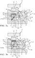
- the stroke-increasing arrangement 40 comprises a pair of angled members 41, 42.
- Each angled member 41, 42 comprises a short hollow column with a right-angled triangular cross-section. Accordingly, each angled member 41, 42 has three external planar faces 41a - c and 42a - c respectively, disposed at angles to one another.
- the angled members 41, 42 are configured to translate reciprocating movement along a first/ reciprocating rider axis D-D' to reciprocating movement along a second/ pumping axis A-A'.
- the second/ pumping axis A-A' orientation is substantially perpendicular to the first/ reciprocating rider axis D-D'.
- each angled member 41, 42 comprises a contact face 41a, 42a, an engagement face 41b, 42b and a guided face 41c, 42c.
- the contact faces 41a, 42a are configured for contact with the other angled member 41, 42 and as such, in order to translate the orientation of movement, the plane of the contact face 41a, 42a of each angled member 41, 42 is disposed at an angle F to the second/ pumping axis A-A' and at an angle G to the first/ reciprocating rider axis D-D'. Accordingly, the contact faces 41a, 42a form the hypotenuse of the right-angled column.
- the angle F at which the contact faces 41a, 42a are disposed has an impact on the extent of lift and drop of the plunger 12.
- the angle F is set at 48° which has been shown to be capable of achieving a range of movement of 7.18 mm.
- the angle F is set at 40° which has been shown to be capable of achieving a range of movement of 9.53 mm.
- a 45° angle F provides an 8 mm lift and drop and a 43° angle F provides 8.53 mm lift and drop.
- the angled members 41, 42 are adapted to be interchangeable with other pairs of angled members having a different angle F and a different lift and drop (which will likely be dictated by the height of the pumping head). Therefore, the stroke length can be varied easily by simply swapping out the angled members 41, 42 for alternative angled members with a different angle F.
- Each engagement face 41b, 42b is configured to engage a driving component of the drive assembly, e.g. a load face 34 of the rider 30, or a driven component of the pumping assembly, e.g. a tappet or alternatively, a driven end of a plunger 12.
- the engagement faces 41b, 42b comprise one of the pair of catheti faces formed by the right-angled column.
- the guided faces 41c, 42c are configured for guided sliding contact with a guiding face 51a, 52a provided by the chamber 50 of the drive housing.
- the guided faces 41c, 42c comprise the other of the pair of catheti faces formed by the right-angled column and as such, is disposed at a right-angle to the respective engagement face 41b, 42b.
- Each guided face 41c, 42c is provided at angle F to that of its respective contact face 41a, 42a.
- the engagement face 41b of at least the first angled member 41 comprises an upstanding lip 41d along an edge adjoining the guided face 41c/ the right-angled adge. Since the angled members 41, 42 are intended to be interchangeable as far as possible, both angled members 41, 42 may have an upstanding lip 41d, 42d. However, the lip 41d, 42d may be omitted (as in Figures 3a and 3b ) in order to achieve a greater extent of movement and to accommodate the narrower engagement face 41b, 42b as a result of a more acute angle F.
- the drive housing comprises an adapted chamber 50 disposed between the rider 30 and the plunger 12.
- the chamber 50 comprises a first chamber wall 51 substantially parallel with the first/ reciprocating rider axis D-D' and a second chamber wall 52 substantially parallel with the second/ pumping axis A-A'. Accordingly, in the shown embodiments, the two walls 51, 52 meet in a substantially right-angled corner, which is dictated by the perpendicular relationship between the first/ reciprocating rider axis D-D' and the second/ pumping axis A-A'. However, should the relationship between the first/ reciprocating rider axis D-D' and the second/ pumping axis A-A' be different, the relative orientation of the between the two walls 51, 52 would potentially mirror that relationship.
- the second chamber wall 52 functions as the second guiding face 52a for the guided face 42c of the second angled member 42.
- the first chamber wall 51 comprises a protrusion 53 comprising a leading face 51b, the first guiding face 51a and a trailing face 51c.
- the leading face 51b is substantially perpendicular to the chamber wall 51.
- the guiding face 51a is substantially parallel with the chamber wall 51 and linked with the leading face 51b.
- the trailing face 51c slopes away from the guiding face 51a back towards the chamber wall 51.
- the trailing face 51b meets the first chamber wall 51 at the junction with the second chamber wall 52.
- the trailing face 51c comprises an angle of approximately 45° to the guiding face 51a, although it could be disposed at a more or less acute angle, or a 90° angle (mirroring the leading face 51b).
- the first guiding face 51a is narrower than the span of the guided face 41c between the leading and trailing faces 51b, 51c and so, the guided face 41c of the angled member 41 is configured to partially overhang the guiding face 51a.
- the narrower guiding face 51a also facilitates the existence and slope of the trailing face 51c in order that the second angled member 42 is able to drop below the level of the first guiding face 51a for a greater range of movement along the second/ pumping axis A-A'.
- the second angled member 42 is disposed with the engagement face 42b facing the end 12a of the plunger 12 and the guided face 42c against the guiding face 52a of the second chamber wall 52.
- the second angled member 42 may be in a dropped position and may be substantially resting in the space between the trailing face 51c and the second chamber wall 52. In this position, the contact face 42a is in a generally downwardly disposed orientation (angled).
- the first angled member 41 is slid in 'under' the second angled member 42, with the guided face 41c disposed downwardly and resting against the first guiding face 51a, which places the contact face 41a in an generally upwardly disposed orientation (angled) to meet the second contact face 42a.
- the first engagement face 41b is in an orientation to interface with the load face 34 of the rider 30.
- the plunger 12 In a first position, as shown in Figures 2a and 3a , the plunger 12 is in a 'dropped' state sitting against the engagement face 42b of the 'dropped' second angled member 42, part of which nestles in the space between the trailing face 51c of the protrusion 53 and the second chamber wall 52.
- An upper portion of the second contact face 42a is resting against a lower portion of the first contact face 41a of the first angled member 41, thereby maintaining the angle F and the orientation of the contact face 42a relative to the pumping axis A-A'.
- the first angled member 41 overhangs the guiding face 51a on protrusion 53 by partially extending over the leading face 51b. Accordingly, the first angled member 41 is trapped between the contact face 42a of the second angled member 42, the first guiding face 51a and the load face 34 of the rider 30 to retain its orientation.
- the load face 34 of the rider 30 moves along the axis D-D' towards the second chamber wall 52 pushing the engagement face 41b of the first angled member 41 along the first/ reciprocating rider axis D' ⁇ D.
- the guided face 41c of the first angled member 41 slides along the guiding face 51a of the protrusion 53 in the first chamber wall 51 until the lip 41d meets the leading face 51b of the protrusion 53 (where a lip is present) as shown in Figures 2b and 3b .
- the lip 41d prevents over extension of the first angled member 41 which may otherwise hit the second chamber wall 52 during operation.
- the second contact face 42a substantially overlies the first contact face 41a to be fully supported between the first angled member 41 and the second guiding face 52a of the chamber 50.
- the force of a return spring (not shown) located around the plunger 12, causes the engagement face 42b to be driven downwardly and the second angled member 42 to drop whilst supported by the guiding face 52a.
- This downward movement of the second angled member 42 forces the first angled member back along the first axis D-D' due to the sliding interaction of the two contact faces 41a, 42a.
- the first angled member 41 follows the receding face 34 of the rider 30 until it returns fully to the dropped position.
- the drive assembly is constructed to drive two pumping assemblies 10 and therefore, two stroke-enhancing mechanisms 40.
- the pump may comprise first and second pumping assemblies 10 disposed at approximately 180° to one another with offset pumping axes.
- the opposite faces 34 of the rider 30 are able to accommodate such an arrangement, wherein as the rider 30 'drops' relative to a first pumping assembly 10, the rider 30 is 'lifted' in relation to the second pumping assembly 10 and vice versa.
- each flat surface 34 of the rider 30 would contact a tappet which in turn would contact the bottom end 12a of the plunger 12 (in much the same arrangement as shown in Figure 1 ).
- angle F has a significant impact of the range of movement of the plunger 12.
- a shallower angle F appears to increase the range of movement, which in turn increases the pump capacity.
- the examples discussed above are based upon a rider journal 24/ rear bearing 26 throw T of 8 mm due to the enlarged rear bearing 26 and the stroke-increasing arrangement 40 aims to compensate for the loss of plunger lift.
- a greater throw T of 10.5 mm e.g. little or no enlargement of the rear bearing 26, greater pump capacities could be achieved.
- the pump capacity increases exponentially with an increase in angle F.
- the arrangement will also support a second pumping assembly 10 incorporated on an opposing side of the rider 30 to double the capacity of the pump.
- This can either be located so as to be side-by-side with the first pumping assembly, or opposite the first pumping assembly, or even at a different angled orientation (in the latter case with an adapted rider 30).
- a side-by-side arrangement it could be possible to fit one long high pressure dual-head with one high pressure outlet.
Landscapes
- Engineering & Computer Science (AREA)
- Mechanical Engineering (AREA)
- General Engineering & Computer Science (AREA)
- Chemical & Material Sciences (AREA)
- Combustion & Propulsion (AREA)
- Reciprocating Pumps (AREA)
Claims (14)
- Hochdruckkraftstoffpumpe mit zumindest einer Pumpanordnung (10) und einer Antriebsanordnung (20), wobei die oder jede Pumpanordnung (10) einen Kolben (12) aufweist, der zur Hin- und Herbewegung entlang einer Pumpachse (A-A') ausgebildet ist, wobei die Antriebsanordnung (20) ein Antriebsmittel und eine Antriebswelle (22) aufweist, die einen Reiterzapfen (24) angegrenzt an ein vorderes Lager (25) und ein hinteres Lager (26) aufweist, wobei der Reiterzapfen (24) und zumindest das hintere Lager (26) zueinander versetzte Achsen (B-B', C-C') aufweisen, wobei ein Reiter (30) auf den Reiterzapfen (24) angepasst ist, um eine Bewegung des Reiters (30) entlang eines exzentrischen Rotationspfads zu bewirken, wobei der Reiter (30) zumindest eine nach außen weisende ebene Oberfläche (34) zum Zusammenwirken mit der Pumpanordnung (10) aufweist, wobei die Antriebsanordnung (20) eine hubsteigemde Anordnung (40) aufweist, die zwischen dem Reiter (30) und der Pumpanordnung (10) angeordnet ist, wobei die Hochdruckkraftstoffpumpe dadurch gekennzeichnet ist, dass die hubsteigernde Anordnung (40) zumindest zwei abgewinkelte Elemente (41, 42) aufweist, die konfiguriert sind zum Umsetzen einer Bewegung entlang einer ersten Achse (D-D') zu entlang der Pumpachse (A-A').
- Die Pumpe gemäß Anspruch 1, wobei die Antriebsanordnung (20) ein vergrößertes hinteres Lager (26) aufweist, was eine Zunahme des Durchmessers des hinteren Lagers (26) bis zu und einschließlich des Durchmessers des Reiterzapfens (24) bedeutet, während die versetzten Achsen (B-B', C-C') beibehalten werden.
- Die Pumpe gemäß Anspruch 1, wobei die erste Achse (D-D') dieselbe ist wie eine Hin- und Herbewegungsachse (D-D') des Reiters (30) und die Pumpachse (A-A') dieselbe ist wie die Pumpachse (A-A').
- Die Pumpe gemäß einem der Ansprüche 1 oder 3, wobei jedes abgewinkelte Element (41,42) zumindest eine planare Kontaktfläche (41a, 42a) zum Kontakt mit einem anderen abgewinkelten Element (41, 42) aufweist und konfiguriert ist, in einem Winkel (F) zu sowohl der ersten Achse (D-D') als auch der Pumpachse (A-A') angeordnet zu sein.
- Die Pumpe gemäß Anspruch 4, wobei der Winkel (F) zwischen 30° und 70° beträgt.
- Die Pumpe gemäß einem der Ansprüche 1 bis 5, wobei zwei der abgewinkelten Elemente (41, 42) eine planare Eingriffsfläche (41b, 42b) aufweisen zum Eingriff mit einer Antriebskomponente (30) der Antriebsanordnung (20) oder einer angetriebenen Komponente (12) der Pumpanordnung (10).
- Die Pumpe gemäß Anspruch 6, wobei die Ebene der Eingriffsfläche (41b) eines ersten abgewinkelten Elements (41) in einer ersten Ausrichtung senkrecht zu der ersten/ Reiter-Hin- und Herbewegungsachse (D-D') vorgesehen ist und die Ebene der Eingriffsfläche (41b) eines zweiten abgewinkelten Elements (42) in einer zweiten Ausrichtung senkrecht zu der zweiten/Pumpachse (A-A') vorgesehen ist.
- Die Pumpe gemäß einem der Ansprüche 1 bis 7, wobei zwei der abgewinkelten Elemente (41, 42) eine geführte Fläche (41c, 42c) aufweisen, die in einem Winkel (F) zu der ihrer jeweiligen Kontaktfläche (41a, 42a) vorgesehen ist, für einen geführten Gleitkontakt mit einer Führungsfläche (41c, 42c), die von dem Antriebsgehäuse vorgesehen ist.
- Die Pumpe gemäß einem der Ansprüche 1 bis 8, wobei die abgewinkelten Elemente (41, 42) einen dreieckigen Querschnitt aufweisen.
- Die Pumpe gemäß einem der Ansprüche 8 oder 9, wobei das Antriebsgehäuse eine angepasste Kammer (50) aufweist, die zwischen dem Reiter (30) und dem Kolben (12) angeordnet ist, die zumindest zwei Führungsflächen (51a, 52a) für einen Kontakt mit den geführten Flächen (41c, 42c) der abgewinkelten Elemente (41, 42) aufweist.
- Die Pumpe gemäß Anspruch 10, wobei die Kammer (50) aufweist eine erste Führungsfläche (51a), die parallel zu der ersten/Hin- und Herbewegungs-Reiter-Achse (D-D') ist, die durch einen Vorsprung (53) von einer Wand der ersten Kammer (50) vorgesehen ist, und eine zweite Führungsfläche (52a), die parallel zu der zweiten/Pumpachse (A-A') ist und durch eine zweite Kammerwand (52) vorgesehen ist.
- Die Pumpe gemäß Anspruch 11, wobei die erste geführte Fläche (41c) konfiguriert ist, teilweise die erste Führungsfläche (51a) zu überragen.
- Die Pumpe gemäß Anspruch 12, wobei der Vorsprung (53) eine geneigte hintere Fläche (51c) aufweist, die geformt ist, abzufallen vor einem Ende der ersten Kammerwand (51) und/oder vor einem Kontaktieren der zweiten Kammerwand (52).
- Die Pumpe gemäß einem der Ansprüche 4 bis 13, wobei die abgewinkelten Elemente (41, 42) mit anderen abgewinkelten Elementen, die einen anderen Winkel (F) aufweisen, austauschbar sind.
Applications Claiming Priority (1)
| Application Number | Priority Date | Filing Date | Title |
|---|---|---|---|
| GBGB1515435.4A GB201515435D0 (en) | 2015-09-01 | 2015-09-01 | High pressure fuel pump |
Publications (2)
| Publication Number | Publication Date |
|---|---|
| EP3139029A1 EP3139029A1 (de) | 2017-03-08 |
| EP3139029B1 true EP3139029B1 (de) | 2018-10-31 |
Family
ID=54326584
Family Applications (1)
| Application Number | Title | Priority Date | Filing Date |
|---|---|---|---|
| EP16185570.5A Active EP3139029B1 (de) | 2015-09-01 | 2016-08-24 | Hochdruckbrennstoffpumpe |
Country Status (2)
| Country | Link |
|---|---|
| EP (1) | EP3139029B1 (de) |
| GB (1) | GB201515435D0 (de) |
Family Cites Families (4)
| Publication number | Priority date | Publication date | Assignee | Title |
|---|---|---|---|---|
| DE3542938A1 (de) * | 1985-12-04 | 1987-06-11 | Rexroth Mannesmann Gmbh | Kraftstoffeinspritzpumpe |
| AT410246B (de) * | 1999-06-25 | 2003-03-25 | Hoerbiger Hydraulik | Radialkolbenpumpe |
| JP4428327B2 (ja) * | 2005-09-22 | 2010-03-10 | 株式会社デンソー | 高圧燃料供給ポンプ |
| WO2016096205A1 (en) * | 2014-12-17 | 2016-06-23 | Delphi International Operations Luxembourg S.À R.L. | Fuel pump assembly |
-
2015
- 2015-09-01 GB GBGB1515435.4A patent/GB201515435D0/en not_active Ceased
-
2016
- 2016-08-24 EP EP16185570.5A patent/EP3139029B1/de active Active
Non-Patent Citations (1)
| Title |
|---|
| None * |
Also Published As
| Publication number | Publication date |
|---|---|
| GB201515435D0 (en) | 2015-10-14 |
| EP3139029A1 (de) | 2017-03-08 |
Similar Documents
| Publication | Publication Date | Title |
|---|---|---|
| EP2657505B1 (de) | Hochdruckkraftstoffpumpenanordnung | |
| US10260614B2 (en) | Cam follower with anti-rotation device | |
| JP2010037997A (ja) | 燃料供給ポンプ | |
| US9567960B2 (en) | Fuel pump tappet assembly | |
| EP2650538A1 (de) | Hydraulische schrägplatten-rotationsmaschine | |
| KR20120052293A (ko) | 고압 펌프 | |
| CN100458150C (zh) | 高压泵 | |
| JP5166198B2 (ja) | ポンプアッセンブリ及びこのポンプアッセンブリ用のタペット | |
| WO2018077652A1 (en) | Plunger-type pump and cam driven element thereof | |
| EP3234356B1 (de) | Brennstoffpumpenanordnung | |
| CN101035984A (zh) | 具有滚轮挺杆的径向活塞泵 | |
| EP3139029A1 (de) | Hochdruckbrennstoffpumpe | |
| KR101697770B1 (ko) | 연료 펌프 | |
| EP3368766B1 (de) | Schmierung eines rollenschuhs einehochdruckkraftstoffpumpe | |
| WO2015132052A1 (en) | Tappet arrangement and pump | |
| CN106438145B (zh) | 共轨高压泵的无销挺柱部件 | |
| JP5395308B2 (ja) | 高圧ポンプ | |
| KR20140037707A (ko) | 고압연료펌프 | |
| CN207470244U (zh) | 一种带防转装置的滚轮挺杆 | |
| KR20130118182A (ko) | 내연기관의 고압펌프 | |
| KR102615466B1 (ko) | 펌핑 조립체 | |
| JP6239094B2 (ja) | 燃料噴射ポンプ | |
| EP3111080A1 (de) | Brennstoffpumpmechanismus | |
| US20200191245A1 (en) | Direction of motion changing device | |
| US8850925B2 (en) | Follower member |
Legal Events
| Date | Code | Title | Description |
|---|---|---|---|
| PUAI | Public reference made under article 153(3) epc to a published international application that has entered the european phase |
Free format text: ORIGINAL CODE: 0009012 |
|
| STAA | Information on the status of an ep patent application or granted ep patent |
Free format text: STATUS: THE APPLICATION HAS BEEN PUBLISHED |
|
| AK | Designated contracting states |
Kind code of ref document: A1 Designated state(s): AL AT BE BG CH CY CZ DE DK EE ES FI FR GB GR HR HU IE IS IT LI LT LU LV MC MK MT NL NO PL PT RO RS SE SI SK SM TR |
|
| AX | Request for extension of the european patent |
Extension state: BA ME |
|
| STAA | Information on the status of an ep patent application or granted ep patent |
Free format text: STATUS: REQUEST FOR EXAMINATION WAS MADE |
|
| 17P | Request for examination filed |
Effective date: 20170908 |
|
| RBV | Designated contracting states (corrected) |
Designated state(s): AL AT BE BG CH CY CZ DE DK EE ES FI FR GB GR HR HU IE IS IT LI LT LU LV MC MK MT NL NO PL PT RO RS SE SI SK SM TR |
|
| GRAP | Despatch of communication of intention to grant a patent |
Free format text: ORIGINAL CODE: EPIDOSNIGR1 |
|
| STAA | Information on the status of an ep patent application or granted ep patent |
Free format text: STATUS: GRANT OF PATENT IS INTENDED |
|
| INTG | Intention to grant announced |
Effective date: 20180613 |
|
| GRAS | Grant fee paid |
Free format text: ORIGINAL CODE: EPIDOSNIGR3 |
|
| GRAA | (expected) grant |
Free format text: ORIGINAL CODE: 0009210 |
|
| STAA | Information on the status of an ep patent application or granted ep patent |
Free format text: STATUS: THE PATENT HAS BEEN GRANTED |
|
| AK | Designated contracting states |
Kind code of ref document: B1 Designated state(s): AL AT BE BG CH CY CZ DE DK EE ES FI FR GB GR HR HU IE IS IT LI LT LU LV MC MK MT NL NO PL PT RO RS SE SI SK SM TR |
|
| REG | Reference to a national code |
Ref country code: CH Ref legal event code: EP Ref country code: GB Ref legal event code: FG4D |
|
| REG | Reference to a national code |
Ref country code: AT Ref legal event code: REF Ref document number: 1059719 Country of ref document: AT Kind code of ref document: T Effective date: 20181115 |
|
| REG | Reference to a national code |
Ref country code: DE Ref legal event code: R096 Ref document number: 602016006754 Country of ref document: DE |
|
| REG | Reference to a national code |
Ref country code: IE Ref legal event code: FG4D |
|
| REG | Reference to a national code |
Ref country code: DE Ref legal event code: R081 Ref document number: 602016006754 Country of ref document: DE Owner name: DELPHI TECHNOLOGIES IP LIMITED, BB Free format text: FORMER OWNER: DELPHI INTERNATIONAL OPERATIONS LUXEMBOURG S.A R.L., BASCHARAGE, LU |
|
| REG | Reference to a national code |
Ref country code: NL Ref legal event code: MP Effective date: 20181031 |
|
| REG | Reference to a national code |
Ref country code: LT Ref legal event code: MG4D |
|
| REG | Reference to a national code |
Ref country code: GB Ref legal event code: 732E Free format text: REGISTERED BETWEEN 20190222 AND 20190227 |
|
| REG | Reference to a national code |
Ref country code: AT Ref legal event code: MK05 Ref document number: 1059719 Country of ref document: AT Kind code of ref document: T Effective date: 20181031 |
|
| PG25 | Lapsed in a contracting state [announced via postgrant information from national office to epo] |
Ref country code: HR Free format text: LAPSE BECAUSE OF FAILURE TO SUBMIT A TRANSLATION OF THE DESCRIPTION OR TO PAY THE FEE WITHIN THE PRESCRIBED TIME-LIMIT Effective date: 20181031 Ref country code: AT Free format text: LAPSE BECAUSE OF FAILURE TO SUBMIT A TRANSLATION OF THE DESCRIPTION OR TO PAY THE FEE WITHIN THE PRESCRIBED TIME-LIMIT Effective date: 20181031 Ref country code: LT Free format text: LAPSE BECAUSE OF FAILURE TO SUBMIT A TRANSLATION OF THE DESCRIPTION OR TO PAY THE FEE WITHIN THE PRESCRIBED TIME-LIMIT Effective date: 20181031 Ref country code: IS Free format text: LAPSE BECAUSE OF FAILURE TO SUBMIT A TRANSLATION OF THE DESCRIPTION OR TO PAY THE FEE WITHIN THE PRESCRIBED TIME-LIMIT Effective date: 20190228 Ref country code: PL Free format text: LAPSE BECAUSE OF FAILURE TO SUBMIT A TRANSLATION OF THE DESCRIPTION OR TO PAY THE FEE WITHIN THE PRESCRIBED TIME-LIMIT Effective date: 20181031 Ref country code: BG Free format text: LAPSE BECAUSE OF FAILURE TO SUBMIT A TRANSLATION OF THE DESCRIPTION OR TO PAY THE FEE WITHIN THE PRESCRIBED TIME-LIMIT Effective date: 20190131 Ref country code: ES Free format text: LAPSE BECAUSE OF FAILURE TO SUBMIT A TRANSLATION OF THE DESCRIPTION OR TO PAY THE FEE WITHIN THE PRESCRIBED TIME-LIMIT Effective date: 20181031 Ref country code: NO Free format text: LAPSE BECAUSE OF FAILURE TO SUBMIT A TRANSLATION OF THE DESCRIPTION OR TO PAY THE FEE WITHIN THE PRESCRIBED TIME-LIMIT Effective date: 20190131 Ref country code: FI Free format text: LAPSE BECAUSE OF FAILURE TO SUBMIT A TRANSLATION OF THE DESCRIPTION OR TO PAY THE FEE WITHIN THE PRESCRIBED TIME-LIMIT Effective date: 20181031 Ref country code: LV Free format text: LAPSE BECAUSE OF FAILURE TO SUBMIT A TRANSLATION OF THE DESCRIPTION OR TO PAY THE FEE WITHIN THE PRESCRIBED TIME-LIMIT Effective date: 20181031 |
|
| PG25 | Lapsed in a contracting state [announced via postgrant information from national office to epo] |
Ref country code: PT Free format text: LAPSE BECAUSE OF FAILURE TO SUBMIT A TRANSLATION OF THE DESCRIPTION OR TO PAY THE FEE WITHIN THE PRESCRIBED TIME-LIMIT Effective date: 20190301 Ref country code: GR Free format text: LAPSE BECAUSE OF FAILURE TO SUBMIT A TRANSLATION OF THE DESCRIPTION OR TO PAY THE FEE WITHIN THE PRESCRIBED TIME-LIMIT Effective date: 20190201 Ref country code: RS Free format text: LAPSE BECAUSE OF FAILURE TO SUBMIT A TRANSLATION OF THE DESCRIPTION OR TO PAY THE FEE WITHIN THE PRESCRIBED TIME-LIMIT Effective date: 20181031 Ref country code: SE Free format text: LAPSE BECAUSE OF FAILURE TO SUBMIT A TRANSLATION OF THE DESCRIPTION OR TO PAY THE FEE WITHIN THE PRESCRIBED TIME-LIMIT Effective date: 20181031 Ref country code: AL Free format text: LAPSE BECAUSE OF FAILURE TO SUBMIT A TRANSLATION OF THE DESCRIPTION OR TO PAY THE FEE WITHIN THE PRESCRIBED TIME-LIMIT Effective date: 20181031 Ref country code: NL Free format text: LAPSE BECAUSE OF FAILURE TO SUBMIT A TRANSLATION OF THE DESCRIPTION OR TO PAY THE FEE WITHIN THE PRESCRIBED TIME-LIMIT Effective date: 20181031 |
|
| PG25 | Lapsed in a contracting state [announced via postgrant information from national office to epo] |
Ref country code: DK Free format text: LAPSE BECAUSE OF FAILURE TO SUBMIT A TRANSLATION OF THE DESCRIPTION OR TO PAY THE FEE WITHIN THE PRESCRIBED TIME-LIMIT Effective date: 20181031 Ref country code: CZ Free format text: LAPSE BECAUSE OF FAILURE TO SUBMIT A TRANSLATION OF THE DESCRIPTION OR TO PAY THE FEE WITHIN THE PRESCRIBED TIME-LIMIT Effective date: 20181031 Ref country code: IT Free format text: LAPSE BECAUSE OF FAILURE TO SUBMIT A TRANSLATION OF THE DESCRIPTION OR TO PAY THE FEE WITHIN THE PRESCRIBED TIME-LIMIT Effective date: 20181031 |
|
| REG | Reference to a national code |
Ref country code: DE Ref legal event code: R097 Ref document number: 602016006754 Country of ref document: DE |
|
| PG25 | Lapsed in a contracting state [announced via postgrant information from national office to epo] |
Ref country code: RO Free format text: LAPSE BECAUSE OF FAILURE TO SUBMIT A TRANSLATION OF THE DESCRIPTION OR TO PAY THE FEE WITHIN THE PRESCRIBED TIME-LIMIT Effective date: 20181031 Ref country code: EE Free format text: LAPSE BECAUSE OF FAILURE TO SUBMIT A TRANSLATION OF THE DESCRIPTION OR TO PAY THE FEE WITHIN THE PRESCRIBED TIME-LIMIT Effective date: 20181031 Ref country code: SM Free format text: LAPSE BECAUSE OF FAILURE TO SUBMIT A TRANSLATION OF THE DESCRIPTION OR TO PAY THE FEE WITHIN THE PRESCRIBED TIME-LIMIT Effective date: 20181031 Ref country code: SK Free format text: LAPSE BECAUSE OF FAILURE TO SUBMIT A TRANSLATION OF THE DESCRIPTION OR TO PAY THE FEE WITHIN THE PRESCRIBED TIME-LIMIT Effective date: 20181031 |
|
| PLBE | No opposition filed within time limit |
Free format text: ORIGINAL CODE: 0009261 |
|
| STAA | Information on the status of an ep patent application or granted ep patent |
Free format text: STATUS: NO OPPOSITION FILED WITHIN TIME LIMIT |
|
| 26N | No opposition filed |
Effective date: 20190801 |
|
| PG25 | Lapsed in a contracting state [announced via postgrant information from national office to epo] |
Ref country code: SI Free format text: LAPSE BECAUSE OF FAILURE TO SUBMIT A TRANSLATION OF THE DESCRIPTION OR TO PAY THE FEE WITHIN THE PRESCRIBED TIME-LIMIT Effective date: 20181031 |
|
| PG25 | Lapsed in a contracting state [announced via postgrant information from national office to epo] |
Ref country code: TR Free format text: LAPSE BECAUSE OF FAILURE TO SUBMIT A TRANSLATION OF THE DESCRIPTION OR TO PAY THE FEE WITHIN THE PRESCRIBED TIME-LIMIT Effective date: 20181031 |
|
| PG25 | Lapsed in a contracting state [announced via postgrant information from national office to epo] |
Ref country code: MC Free format text: LAPSE BECAUSE OF FAILURE TO SUBMIT A TRANSLATION OF THE DESCRIPTION OR TO PAY THE FEE WITHIN THE PRESCRIBED TIME-LIMIT Effective date: 20181031 Ref country code: LU Free format text: LAPSE BECAUSE OF NON-PAYMENT OF DUE FEES Effective date: 20190824 Ref country code: LI Free format text: LAPSE BECAUSE OF NON-PAYMENT OF DUE FEES Effective date: 20190831 Ref country code: CH Free format text: LAPSE BECAUSE OF NON-PAYMENT OF DUE FEES Effective date: 20190831 |
|
| REG | Reference to a national code |
Ref country code: BE Ref legal event code: MM Effective date: 20190831 |
|
| PG25 | Lapsed in a contracting state [announced via postgrant information from national office to epo] |
Ref country code: IE Free format text: LAPSE BECAUSE OF NON-PAYMENT OF DUE FEES Effective date: 20190824 |
|
| PG25 | Lapsed in a contracting state [announced via postgrant information from national office to epo] |
Ref country code: BE Free format text: LAPSE BECAUSE OF NON-PAYMENT OF DUE FEES Effective date: 20190831 |
|
| PG25 | Lapsed in a contracting state [announced via postgrant information from national office to epo] |
Ref country code: CY Free format text: LAPSE BECAUSE OF FAILURE TO SUBMIT A TRANSLATION OF THE DESCRIPTION OR TO PAY THE FEE WITHIN THE PRESCRIBED TIME-LIMIT Effective date: 20181031 |
|
| PG25 | Lapsed in a contracting state [announced via postgrant information from national office to epo] |
Ref country code: HU Free format text: LAPSE BECAUSE OF FAILURE TO SUBMIT A TRANSLATION OF THE DESCRIPTION OR TO PAY THE FEE WITHIN THE PRESCRIBED TIME-LIMIT; INVALID AB INITIO Effective date: 20160824 Ref country code: MT Free format text: LAPSE BECAUSE OF FAILURE TO SUBMIT A TRANSLATION OF THE DESCRIPTION OR TO PAY THE FEE WITHIN THE PRESCRIBED TIME-LIMIT Effective date: 20181031 |
|
| PG25 | Lapsed in a contracting state [announced via postgrant information from national office to epo] |
Ref country code: MK Free format text: LAPSE BECAUSE OF FAILURE TO SUBMIT A TRANSLATION OF THE DESCRIPTION OR TO PAY THE FEE WITHIN THE PRESCRIBED TIME-LIMIT Effective date: 20181031 |
|
| P01 | Opt-out of the competence of the unified patent court (upc) registered |
Effective date: 20230327 |
|
| REG | Reference to a national code |
Ref country code: DE Ref legal event code: R081 Ref document number: 602016006754 Country of ref document: DE Owner name: PHINIA DELPHI LUXEMBOURG SARL, LU Free format text: FORMER OWNER: DELPHI TECHNOLOGIES IP LIMITED, ST. MICHAEL, BB |
|
| PGFP | Annual fee paid to national office [announced via postgrant information from national office to epo] |
Ref country code: DE Payment date: 20250709 Year of fee payment: 10 |
|
| PGFP | Annual fee paid to national office [announced via postgrant information from national office to epo] |
Ref country code: GB Payment date: 20250710 Year of fee payment: 10 |
|
| PGFP | Annual fee paid to national office [announced via postgrant information from national office to epo] |
Ref country code: FR Payment date: 20250709 Year of fee payment: 10 |