EP3138720B1 - Verfahren und vorrichtung zur anpassung einer fahrpedalkennlinie - Google Patents
Verfahren und vorrichtung zur anpassung einer fahrpedalkennlinie Download PDFInfo
- Publication number
- EP3138720B1 EP3138720B1 EP16001656.4A EP16001656A EP3138720B1 EP 3138720 B1 EP3138720 B1 EP 3138720B1 EP 16001656 A EP16001656 A EP 16001656A EP 3138720 B1 EP3138720 B1 EP 3138720B1
- Authority
- EP
- European Patent Office
- Prior art keywords
- accelerator pedal
- engine torque
- characteristic curve
- vehicle
- desired engine
- Prior art date
- Legal status (The legal status is an assumption and is not a legal conclusion. Google has not performed a legal analysis and makes no representation as to the accuracy of the status listed.)
- Active
Links
Images


Classifications
-
- F—MECHANICAL ENGINEERING; LIGHTING; HEATING; WEAPONS; BLASTING
- F02—COMBUSTION ENGINES; HOT-GAS OR COMBUSTION-PRODUCT ENGINE PLANTS
- F02D—CONTROLLING COMBUSTION ENGINES
- F02D11/00—Arrangements for, or adaptations to, non-automatic engine control initiation means, e.g. operator initiated
- F02D11/06—Arrangements for, or adaptations to, non-automatic engine control initiation means, e.g. operator initiated characterised by non-mechanical control linkages, e.g. fluid control linkages or by control linkages with power drive or assistance
- F02D11/10—Arrangements for, or adaptations to, non-automatic engine control initiation means, e.g. operator initiated characterised by non-mechanical control linkages, e.g. fluid control linkages or by control linkages with power drive or assistance of the electric type
- F02D11/105—Arrangements for, or adaptations to, non-automatic engine control initiation means, e.g. operator initiated characterised by non-mechanical control linkages, e.g. fluid control linkages or by control linkages with power drive or assistance of the electric type characterised by the function converting demand to actuation, e.g. a map indicating relations between an accelerator pedal position and throttle valve opening or target engine torque
-
- F—MECHANICAL ENGINEERING; LIGHTING; HEATING; WEAPONS; BLASTING
- F02—COMBUSTION ENGINES; HOT-GAS OR COMBUSTION-PRODUCT ENGINE PLANTS
- F02D—CONTROLLING COMBUSTION ENGINES
- F02D41/00—Electrical control of supply of combustible mixture or its constituents
- F02D41/02—Circuit arrangements for generating control signals
- F02D41/04—Introducing corrections for particular operating conditions
- F02D41/10—Introducing corrections for particular operating conditions for acceleration
-
- F—MECHANICAL ENGINEERING; LIGHTING; HEATING; WEAPONS; BLASTING
- F02—COMBUSTION ENGINES; HOT-GAS OR COMBUSTION-PRODUCT ENGINE PLANTS
- F02D—CONTROLLING COMBUSTION ENGINES
- F02D41/00—Electrical control of supply of combustible mixture or its constituents
- F02D41/02—Circuit arrangements for generating control signals
- F02D41/14—Introducing closed-loop corrections
- F02D41/1497—With detection of the mechanical response of the engine
-
- F—MECHANICAL ENGINEERING; LIGHTING; HEATING; WEAPONS; BLASTING
- F02—COMBUSTION ENGINES; HOT-GAS OR COMBUSTION-PRODUCT ENGINE PLANTS
- F02D—CONTROLLING COMBUSTION ENGINES
- F02D11/00—Arrangements for, or adaptations to, non-automatic engine control initiation means, e.g. operator initiated
- F02D11/06—Arrangements for, or adaptations to, non-automatic engine control initiation means, e.g. operator initiated characterised by non-mechanical control linkages, e.g. fluid control linkages or by control linkages with power drive or assistance
- F02D11/10—Arrangements for, or adaptations to, non-automatic engine control initiation means, e.g. operator initiated characterised by non-mechanical control linkages, e.g. fluid control linkages or by control linkages with power drive or assistance of the electric type
- F02D2011/101—Arrangements for, or adaptations to, non-automatic engine control initiation means, e.g. operator initiated characterised by non-mechanical control linkages, e.g. fluid control linkages or by control linkages with power drive or assistance of the electric type characterised by the means for actuating the throttles
- F02D2011/102—Arrangements for, or adaptations to, non-automatic engine control initiation means, e.g. operator initiated characterised by non-mechanical control linkages, e.g. fluid control linkages or by control linkages with power drive or assistance of the electric type characterised by the means for actuating the throttles at least one throttle being moved only by an electric actuator
-
- F—MECHANICAL ENGINEERING; LIGHTING; HEATING; WEAPONS; BLASTING
- F02—COMBUSTION ENGINES; HOT-GAS OR COMBUSTION-PRODUCT ENGINE PLANTS
- F02D—CONTROLLING COMBUSTION ENGINES
- F02D2200/00—Input parameters for engine control
- F02D2200/60—Input parameters for engine control said parameters being related to the driver demands or status
- F02D2200/602—Pedal position
-
- F—MECHANICAL ENGINEERING; LIGHTING; HEATING; WEAPONS; BLASTING
- F02—COMBUSTION ENGINES; HOT-GAS OR COMBUSTION-PRODUCT ENGINE PLANTS
- F02D—CONTROLLING COMBUSTION ENGINES
- F02D2250/00—Engine control related to specific problems or objectives
- F02D2250/18—Control of the engine output torque
- F02D2250/21—Control of the engine output torque during a transition between engine operation modes or states
Definitions
- the invention relates to a method for adapting the accelerator pedal characteristic in a motor vehicle, in which an accelerator pedal characteristic curve describing the relationship between accelerator pedal travel and a requested engine target torque is adapted during driving operation.
- the invention further relates to a device which is designed to carry out the method.
- the torque control of the drive motor is usually regulated electronically. There is no mechanical coupling between accelerator pedal and drive motor.
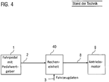
- the accelerator pedal is equipped with a pedal value transmitter 1, which determines the accelerator pedal travel 2 and makes it available to a computing unit 40 for further processing.
- This computing unit 40 uses additional vehicle data 3 (for example a current engine speed) to determine the desired engine torque 8 that is requested by the drive motor 9.
- accelerator pedal characteristics are stored on the computing unit 40 in advance, which assign an accelerator pedal travel 2 an engine target torque 8.
- the accelerator pedal characteristics can be adapted to target criteria with regard to agility, meterability, safety and fuel consumption.
- a corresponding method is, for example, from the EP 1 334 862 A2 known.
- the disclosure DE 10 2010 041 544 A1 suggests for a fuel-efficient vehicle operation to design the accelerator pedal curve degressively for small accelerator pedal travel. As a result, the vehicle is accelerated less. The driving style is calmed down and subsequent braking maneuvers are reduced.
- the drive motor is designed as an internal combustion engine, this method is at the expense of engine efficiency.
- an economical driving style is characterized by acceleration maneuvers with high engine efficiency. Since internal combustion engines typically achieve high engine efficiency at high engine torques close to the full-load characteristic curve, a more progressive accelerator pedal curve would be more sensible in this case.
- the object of the invention is, in particular, to provide such a method, which supports a consumption-optimized and / or engine efficiency-optimized driving style or with which the drive motor can be operated in a most efficient map area in manual driving style.
- a method for adapting the accelerator pedal characteristic in a motor vehicle in which an accelerator pedal characteristic curve describing the relationship between accelerator pedal travel and a requested engine target torque of the drive motor is adapted during a driving operation.
- the method includes the determination of a desired engine torque, in particular a desired engine torque, which enables consumption-optimized operation of the motor vehicle and / or high engine efficiency if it were currently requested as the desired engine torque.
- the desired engine torque therefore corresponds to an instantaneous value for a target engine torque, which is desired as engine torque specification for the drive engine from an engine efficiency and / or consumption point of view, that would be particularly advantageous.
- the current desired engine torque is to be distinguished from the current desired engine torque, which is determined by the current accelerator pedal travel and the current characteristic curve.
- the desired engine torque is preferably determined continuously while driving, so that an instantaneous desired engine torque is determined in short time intervals.
- the accelerator pedal characteristic curve can be adapted as a function of the specific desired engine torque.
- the adaptation takes place in such a way that the adapted accelerator pedal characteristic curve in a region of the characteristic curve that contains an engine target torque corresponding to the specific desired engine torque has a flattened course in comparison to the unadjusted accelerator pedal characteristic curve or is modified degressively in this region.
- an average slope of the modified characteristic curve in a region surrounding the value of the desired engine torque is less than the slope of the original (not adapted) characteristic curve in this region.
- This adaptation of the characteristic curve increases the range of the accelerator pedal travel to which the accelerator pedal characteristic assigns a target engine torque that corresponds to or is close to the desired engine torque. The driver can thus control an operating point of the drive motor more easily by operating it with high efficiency and / or high consumption efficiency.
- the characteristic curve is thus continuously or at least regularly adjusted during driving so that over a long accelerator pedal travel, ie. H.
- An engine target torque is set at least over a further accelerator pedal travel than in the case of an unadjusted characteristic curve, which leads to high engine efficiency and / or high consumption efficiency.
- the desired engine torque can be determined as a function of at least one operating parameter of the motor vehicle, in particular as a function of the efficiency of the drive motor, preferably with the aid of predetermined maps.
- the desired engine torque is determined as a function of an instantaneous engine speed and a previously determined characteristic curve, the characteristic curve associating each engine speed with the engine torque for which the specific consumption is minimum and / or the engine efficiency is maximum.
- This characteristic is referred to in the prior art as the B emin line.
- This variant offers the advantage that the desired engine torque for the respective operating state can be determined with little computational effort and by means of an adapted one Characteristic curve it is easier for the driver to request a target engine torque via the accelerator pedal path, which leads to a high engine efficiency.
- the desired engine torque can also be determined as a function of route information relating to a route section of the motor vehicle lying ahead.
- the route information can, for example, indicate an altitude profile or an expected speed curve on the route section ahead.
- an engine target torque trajectory for the preceding route section and / or time horizon is determined as a function of a predictive route information for a preceding route section of the motor vehicle and minimizes the fuel consumption taking into account predetermined boundary conditions. Furthermore, the desired engine torque is determined as a function of the determined target engine torque trajectory. The current desired engine torque would then correspond to the value of the engine torque trajectory that is assigned to the current driving position.
- a boundary condition can, for example, be a temporal boundary condition, e.g. B. in the form of a minimum time in which the section of road ahead is to be traveled.
- This variant offers the advantage that previous route information is taken into account, so that the total consumption over the route section ahead can be better optimized.
- a desired engine torque can be specified, for example, which is not optimal from the point of view of engine efficiency at the current point in time, but would lead to a consumption-optimized operation of the drive engine overall in view of the predicted optimal engine torque curve when driving through the route.
- the adapted characteristic curve can have a plateau-like course in the area of the flattened course.
- the characteristic curve therefore has no or only a slight slope in the area around the desired engine torque.
- the flattened course can lie in a range between 30% and 80% of the accelerator pedal travel. Furthermore, the flattened course can encompass at least a range from 50% to 60% of the accelerator pedal travel and / or not encompass the range from 0% to 30%, so that the driver can still meter the vehicle acceleration sensitively when the accelerator pedal deflections are small. Furthermore, the area of the flattened course can comprise at least 15%, more preferably at least 30%, of the accelerator pedal travel.
- the adapted characteristic curve can have an S-shaped course, in particular with a degressively designed first section for small accelerator pedal paths, a middle progressively designed section and a plateau-like end section which includes the value of the driver's desired torque.
- the flattened area in particular the plateau-like course, extends to the end area of the accelerator pedal travel, ie. H. up to 100% of the accelerator pedal travel, so that the target engine torque is limited to the target engine torque.
- This variant offers the advantage that the engine is operated with high engine efficiency even with high accelerator pedal deflection.
- the adaptation of the accelerator pedal characteristic does not have to be continuously effective, but can be activated in suitable situations and deactivated again when there is no longer a suitable situation.
- the adaptation of the accelerator pedal characteristic can be activated and / or deactivated as a function of a situation detection of the vehicle and / or the environment.
- the adaptation of the accelerator pedal characteristic should not take place in driving situations in which a greater impairment of driving behavior should be avoided, e.g. B. in critical driving situations.
- An advantageous variant of this embodiment therefore provides that the situation detection determines whether an acceleration situation is present and / or whether an acceleration situation is imminent, ie probably will be done shortly.
- the adaptation of the accelerator pedal characteristic is activated according to this variant if an acceleration situation is or is imminent.
- an acceleration situation may exist or be recognized when a longitudinal vehicle acceleration exceeds a predetermined threshold value and a vehicle speed exceeds a predetermined minimum speed, e.g. B. 30 km / h exceeds.
- the minimum speed ensures that the characteristic curve is not adjusted during acceleration processes when starting off, maneuvering, etc., since the highest possible meterability via the accelerator pedal is desired.
- an impending acceleration situation can be recognized from the fact that a current vehicle speed is below a target speed or maximum speed for a type of road on which the motor vehicle is currently driving by more than a predetermined difference threshold value. In this case, it is likely that the driver will try to accelerate to the target speed or maximum speed in a timely manner.
- a device for adapting the accelerator pedal characteristic in a motor vehicle which is designed to adapt an accelerator pedal characteristic curve describing the relationship between accelerator pedal travel and a requested engine target torque during driving operation.
- the device is designed to carry out the method according to one of the preceding claims. In order to avoid repetitions, features disclosed purely according to the method should also count as functional features of the device and thus be disclosed as disclosed according to the device and be capable of being claimed.
- the invention further relates to a motor vehicle, in particular a commercial vehicle, with a device as disclosed in this document.
- Figure 1 illustrates the adaptation of the accelerator pedal characteristic using a schematic block diagram.
- the accelerator pedal is equipped in a manner known per se with a pedal value transmitter 1 which determines the accelerator pedal travel 2 set by the driver.
- a control unit 40 set up in terms of program technology continuously receives the currently set accelerator pedal travel 2 during driving operation and electronically controls the torque control of the drive motor.
- At least one previously determined accelerator pedal characteristic curve is stored in the arithmetic unit, which assigns a corresponding motor target torque 8 to each value of the accelerator pedal travel, which is transmitted to the drive motor 9 as a torque target torque request. Additional vehicle data 3 can also be used for this.
- the control unit 40 can adapt the at least one stored accelerator pedal characteristic. However, the adaptation of the accelerator pedal characteristic is only activated in suitable driving situations, otherwise deactivated. For this purpose, the control unit 40 is set up to recognize correspondingly suitable driving situations and to activate the adaptation of the accelerator pedal characteristic curve as long as there is a suitable driving situation, and to deactivate it if there is no longer a suitable driving situation. This functionality is identified by reference number 6 and is described in more detail below.
- the control unit 40 is set up to continuously determine a current value for a desired engine torque 12 while driving.
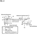
- This functionality of the control unit is in Figure 1 designated by the reference number 5 and in the left diagram of the Figure 2 explained in more detail.
- the consumption map 10 in the form of an engine torque / engine speed diagram shows the so-called “shell curves” B e corresponding to the specific fuel consumption, the full-load characteristic curve 11 and the so-called Bemin characteristic curve Bemin.
- a so-called B emin characteristic curve Bemin is stored in the control device, which in each case associates an engine speed with the engine torque for which the specific consumption is minimal or the engine efficiency is maximum.
- control unit 40 When driving, the control unit 40 continuously receives the current engine speed n via the input data 3 and determines the assigned point P on the B emin characteristic curve 11 or the corresponding current desired engine torque 12 from the engine speed n.
- the stored accelerator pedal characteristic curve is then adjusted as a function of the specific desired engine torque 12.
- This functionality of the control unit is identified by reference number 7.
- the unmatched stored accelerator pedal characteristic (not shown) in the driving mode is adjusted in such a way that the area of the characteristic curve around the value of the desired engine torque has a course 15 flattened in comparison to the unmatched accelerator pedal characteristic.
- the diagram on the right in FIG. 2 shows the adapted characteristic.
- the determined desired engine torque 12 lies in the middle in a region b1 which now has a curve 15 of the characteristic curve 14 that is flattened in comparison to the unmatched characteristic curve.
- the accelerator pedal travel assigned to the desired engine torque 12 is designated by reference number 13.
- the area b1 to the left and right of the desired engine torque 12 is characterized by a slight slope, in particular by a smaller slope than before the characteristic curve was adjusted.
- the accelerator pedal travel 13 assigned to the specific desired engine torque 12 is arranged approximately in the center in the flattened area b1.
- the driver can generate an engine target torque specification 8 that is close to the desired engine torque 12 over a wide accelerator pedal travel range b1. This supports a driving style optimized for engine efficiency. With high accelerator pedal travel, the characteristic curve rises more sharply, so that the full engine torque (100%) can be requested here.
- the accelerator pedal characteristic curve adaptation can also be designed such that the maximum requestable engine target torque 8 is limited to the desired engine torque 12, which is shown in FIG Figure 3 is shown.
- the characteristic curve 14a has a straight course 15a up to the maximum accelerator pedal travel (100%) after the desired engine torque has been reached.
- the area b2 of the flattened course thus extends up to 100% of the accelerator pedal travel. According to this variant, the engine is operated with high engine efficiency even when the accelerator pedal is deflected.
- the accelerator pedal characteristic curve 14 or 14a is continuously adapted so that the flattened area 15, 15a of the characteristic curve is continuously shifted.
- the situation detection 6 enables the accelerator pedal characteristic to be specifically adjusted during particularly advantageous situations and prevents the accelerator pedal characteristic from being adapted in situations in which impairment of the driving behavior is to be expected.
- the acceleration situation can be identified directly from vehicle data. For example, the temporal development of the vehicle speed can be observed and / or the operator's control inputs can be evaluated in order, for. B. deriving from this that there is a vehicle longitudinal acceleration that exceeds a predetermined acceleration threshold.
- probabilities for a future acceleration situation can be derived from ambient conditions. If, for example, the type of road on which the vehicle is currently located is determined, a typical speed typical for this type of road can be compared with the current vehicle speed. If the two speeds deviate significantly from one another, an acceleration situation is likely.
- the limitation of the target engine torque to the target engine torque can also be carried out in accordance with Figure 3 shown example with such a road type-based method in advantageous situations. If, for example, the difference between the typical road speed and vehicle speed is small, instead of adapting the characteristic curve Figure 2 a characteristic curve adjustment according Figure 3 take place in which the maximum requestable engine torque is limited to the desired engine torque according to the characteristic curve 14a. In such a situation, only a small speed difference to the target speed has to be bridged, so that a limitation the maximum demandable engine power to the desired engine torque does not result in a great loss of comfort.
Landscapes
- Engineering & Computer Science (AREA)
- Chemical & Material Sciences (AREA)
- Combustion & Propulsion (AREA)
- Mechanical Engineering (AREA)
- General Engineering & Computer Science (AREA)
- Electric Propulsion And Braking For Vehicles (AREA)
- Hybrid Electric Vehicles (AREA)
- Control Of Vehicle Engines Or Engines For Specific Uses (AREA)
Description
- Die Erfindung betrifft ein Verfahren zur Anpassung der Fahrpedalcharakteristik bei einem Kraftfahrzeug, bei dem während eines Fahrbetriebs eine den Zusammenhang zwischen Fahrpedalweg und einem angeforderten Motorsolldrehmoment beschreibende Fahrpedalkennlinie angepasst wird. Die Erfindung betrifft ferner eine Vorrichtung, die zur Durchführung des Verfahrens ausgebildet ist.
- Bei heutigen Kraftfahrzeugen wird die Drehmomentansteuerung des Antriebsmotors üblicherweise elektronisch geregelt. Eine mechanische Kopplung zwischen Fahrpedal und Antriebsmotor entfällt. Hierzu ist, wie in
Figur 4 dargestellt, das Fahrpedal mit einem Pedalwertgeber 1 ausgerüstet, der den Fahrpedalweg 2 ermittelt und einer Recheneinheit 40 zur weiteren Verarbeitung zur Verfügung stellt. Diese Recheneinheit 40 bestimmt mit zusätzlichen Fahrzeugdaten 3 (z. B. einer aktuellen Motordrehzahl) das Motorsolldrehmoment 8, das vom Antriebsmotor 9 angefordert wird. - Typischerweise sind auf der Recheneinheit 40 vorab bestimmte Fahrpedalkennlinien abgelegt, die dem Fahrpedalweg 2 ein Motorsolldrehmoment 8 zuordnen. Die Fahrpedalkennlinien können dabei situationsabhängig oder fahrerinitiiert an Zielkriterien hinsichtlich Agilität, Dosierbarkeit, Sicherheit und Kraftstoffverbrauch angepasst werden. Ein entsprechendes Verfahren ist beispielsweise aus der
EP 1 334 862 A2 bekannt. - Die Offenlegungsschrift
DE 10 2010 041 544 A1 schlägt für einen kraftstoffeffizienten Fahrzeugbetrieb vor, die Fahrpedalkennlinie bei kleinen Fahrpedalwegen degressiv auszulegen. Dadurch wird das Fahrzeug weniger beschleunigt. Die Fahrweise wird beruhigt, und anschließende Bremsmanöver werden reduziert. - Ist der Antriebsmotor als Verbrennungskraftmaschine ausgeführt, geht dieses Verfahren zu Lasten des Motorwirkungsgrads. Insbesondere für schwere Nutzfahrzeuge, die ein deutlich geringes Verhältnis von Motorleistung zur Fahrzeugmasse aufweisen, zeichnet sich eine wirtschaftliche Fahrweise durch Beschleunigungsmanöver mit hohem Motorwirkungsgrad aus. Da Verbrennungskraftmaschinen typischerweise einen hohen Motorwirkungsgrad bei hohen Motordrehmomenten nahe der Volllastkennlinie erreichen, wäre in diesem Fall eine progressivere Fahrpedalkennlinie sinnvoller.
- Aus der Offenlegungsschrift
DE 10 2008 011 607 A1 ist ein weiteres Verfahren zur situationsabhängigen Anpassung der Fahrpedalcharakteristik in einem Fahrzeug bekannt, bei dem in Abhängigkeit von das Umfeld des Fahrzeugs beschreibenden Informationen der Zusammenhang zwischen Fahrpedalstellung und angefordertem Motormoment modifiziert wird. Insbesondere wird vorgeschlagen, dass die Änderung des Motormoments gegenüber einem linearen Zusammenhang von Fahrpedalstellung und angefordertem Motormoment progressiv oder degressiv modifiziert wird. - Aus der Offenlegungsschrift
US 2008/245338 A1 ist ein Verfahren zur Anpassung der Fahrpedalcharakteristik bei einem Kraftfahrzeug bekannt, gemäß dem eine Fahrpedalkennlinie angepasst wird, um zwischen einer verbrauchsreduzierten Betriebsart und einer Normalbetriebsart umzuschalten. - Es ist eine Aufgabe der Erfindung, ein verbessertes Verfahren zur Anpassung der Fahrpedalcharakteristik in einem Fahrzeug bereitzustellen, mit dem Nachteile herkömmlicher Techniken vermieden werden können. Die Aufgabe der Erfindung ist es insbesondere, ein derartiges Verfahren bereitzustellen, das eine verbrauchsoptimale und/oder motorwirkungsgradoptimale Fahrweise unterstützt bzw. mit dem der Antriebsmotor bei manueller Fahrweise in einem möglichst effizienten Kennfeldbereich betrieben werden kann.
- Diese Aufgaben werden durch Verfahren und Vorrichtungen mit den Merkmalen der unabhängigen Ansprüche gelöst. Vorteilhafte Ausführungsformen und Anwendungen der Erfindung ergeben sich aus den abhängigen Ansprüchen und werden in der folgenden Beschreibung unter teilweiser Bezugnahme auf die Figuren näher erläutert.
- Gemäß einem ersten Gesichtspunkt der Erfindung wird ein Verfahren zur Anpassung der Fahrpedalcharakteristik bei einem Kraftfahrzeug bereitgestellt, bei dem während eines Fahrbetriebs eine den Zusammenhang zwischen Fahrpedalweg und einem angeforderten Motorsolldrehmoment des Antriebsmotors beschreibende Fahrpedalkennlinie angepasst wird.
- Das Verfahren umfasst die Bestimmung eines Motorwunschdrehmoments, insbesondere eines Motorwunschdrehmoments, das einen verbrauchsoptimierten Betrieb des Kraftfahrzeugs und/oder einen hohen Motorwirkungsgrad ermöglicht, falls es als Motorsolldrehmoment momentan angefordert werden würde. Das Motorwunschdrehmoment entspricht daher einem momentanen Wert für ein Motorsolldrehmoment, der als Motordrehmomentvorgabe für den Antriebsmotor aus Motorwirkungsgrad- und/oder Verbrauchsgesichtspunkten erwünscht, d. h. besonders vorteilhaft wäre. Das momentane Motorwunschdrehmoment ist von dem momentanen Motorsolldrehmoment, das durch den aktuellen Fahrpedalweg und die aktuelle Kennlinie festgelegt ist, zu unterscheiden. Die Bestimmung des Motorwunschdrehmoments erfolgt vorzugsweise fortlaufend im Fahrbetrieb, so dass in kurzen Zeitabständen jeweils ein momentanes Motorwunschdrehmoment ermittelt wird.
- Um es dem Fahrer des Kraftfahrzeugs bei manueller Fahrweise, bei der der Fahrer durch Vorgabe eines Fahrpedalwegs ein Motorsolldrehmoment anfordert, zu erleichtern, das Kraftfahrzeug verbrauchsoptimiert und/oder motorwirkungsgradoptimiert zu betreiben, kann die Fahrpedalkennlinie in Abhängigkeit von dem bestimmten Motorwunschdrehmoment angepasst werden. Die Anpassung erfolgt dabei derart, dass die angepasste Fahrpedalkennlinie in einem Bereich der Kennlinie, der ein dem bestimmten Motorwunschdrehmoment entsprechendes Motorsolldrehmoment enthält, einen im Vergleich zur unangepassten Fahrpedalkennlinie abgeflachten Verlauf aufweist bzw. in diesem Bereich degressiv modifiziert ist. Mit anderen Worten ist eine durchschnittliche Steigung der modifizierten Kennlinie in einem den Wert des Motorwunschdrehmomentes umgebenden Bereich geringer als die Steigung der ursprünglichen (nicht angepassten) Kennlinie in diesem Bereich. Durch diese Anpassung der Kennlinie vergrößert sich der Bereich des Fahrpedalwegs, dem die Fahrpedalkennlinie ein Motorsolldrehmoment zuordnet, das dem Motorwunschdrehmoment entspricht oder nahe an diesem liegt. Der Fahrer kann so leichter einen Betriebspunkt des Antriebsmotors ansteuern, indem dieser mit hohem Wirkungsgrad und/oder einer hohen Verbrauchseffizienz betrieben wird.
- Mittels des erfindungsgemäßen Verfahren wird die Kennlinie somit im Fahrbetrieb fortlaufend oder zumindest regelmäßig so angepasst, dass über einen weiten Fahrpedalweg, d. h. zumindest über einen weiteren Fahrpedalweg als bei unangepasster Kennlinie, ein Motorsolldrehmoment gestellt wird, das zu einem hohen Motorwirkungsgrad und/oder einer hohen Verbrauchseffizienz führt.
- Das Motorwunschdrehmoment kann in Abhängigkeit von mindestens einem Betriebsparameter des Kraftfahrzeugs, insbesondere in Abhängigkeit von dem Wirkungsgrad des Antriebsmotors, vorzugsweise mit Hilfe vorab bestimmter Kennfelder ermittelt werden.
- Gemäß einer besonders vorteilhaften Ausführungsform wird das Motorwunschdrehmoment in Abhängigkeit von einer momentanen Motordrehzahl und einer vorab bestimmten Kennlinie bestimmt, wobei die Kennlinie jeder Motordrehzahl dasjenige Motordrehmoment zuordnet, für das der spezifische Verbrauch minimal und/oder der Motorwirkungsgrad maximal ist. Diese Kennlinie wird im Stand der Technik auf als Bemin-Linie bezeichnet. Diese Variante bietet den Vorteil, dass das für den jeweiligen Betriebszustand aktuelle Motorwunschdrehmoment mit geringem rechnerischen Aufwand bestimmt werden kann und mittels einer derart angepassten Kennlinie es dem Fahrer erleichtert wird, über den Fahrpedalweg ein Motorsolldrehmoment anzufordern, das zu einem hohem Motorwirkungsgrad führt.
- Das Motorwunschdrehmoment kann jedoch auch in Abhängigkeit von einer Streckeninformation betreffend einen vorausliegenden Streckenabschnitt des Kraftfahrzeugs bestimmt werden. Die Streckeninformation kann beispielsweise ein Höhenprofil oder einen erwarteten Geschwindigkeitsverlauf auf dem vorausliegenden Streckenabschnitt angeben.
- Erfindungsgemäß wird in Abhängigkeit von einer vorausschauenden Streckeninformation für einen vorausliegenden Streckenabschnitt des Kraftfahrzeugs eine Motorsolldrehmomenttrajektorie für den vorausliegenden Streckenabschnitt und/oder Zeithorizont bestimmt, die unter Berücksichtigung vorgegebener Randbedingungen den Kraftstoffverbrauch minimiert. Ferner wird das Motorwunschdrehmoment in Abhängigkeit von der bestimmten Motorsolldrehmomenttrajektorie festgelegt. Das momentane Motorwunschdrehmoment entspräche dann jeweils dem Wert der Motordrehmomenttrajektorie, die der aktuellen Fahrposition zugeordnet ist. Eine Randbedingung kann beispielsweise eine zeitliche Randbedingung sein, z. B. in Form einer Mindestzeit, in der der vorausliegende Streckenabschnitt durchfahren werden soll.
- Diese Variante bietet den Vorteil, dass vorausliegende Streckeninformationen berücksichtigt werden, so dass der Gesamtverbrauch über den vorausliegenden Streckenabschnitt besser optimiert werden kann. Auf diese Weise kann beispielsweise ein Motorwunschdrehmoment vorgegeben werden, das aus Motorwirkungsgradgesichtspunkten zum aktuellen Zeitpunkt zwar nicht optimal ist, aber im Hinblick auf den prädizierten optimalen Motordrehmomentverlauf beim Durchfahren der Strecke insgesamt zu einem verbrauchsoptimalen Betrieb des Antriebsmotors führen würde.
- Verfahren zur prädiktiven verbrauchsoptimierten Bestimmung einer Motorsolldrehmomenttrajektorie, d. h. zur Vorausberechnung eines auf dem vorausliegendem Streckenabschnitt aus Verbrauchsgesichtspunkten optimierten Verlaufs des Motordrehmoments, sind an sich aus dem Stand der Technik bekannt und daher nicht näher erläutert, siehe beispielsweise Stephan Terwen, Vorausschauende Längsregelung schwerer Lastkraftwagen, Schriften des Instituts für Regelungs- und Steuerungssysteme, Karlsruher Institut für Technologie, Band 06, ISBN 978-3-86644-481-2 (z. B. Abb. 2.12 auf Seite 37 mit entsprechender Beschreibung).
- Gemäß einem weiteren Aspekt kann die angepasste Kennlinie im Bereich des abgeflachten Verlaufs einen plateauartigen Verlauf aufweisen. Die Kennlinie weist somit in dem Bereich um das Motorwunschdrehmoment keine oder nur eine kleine Steigung auf.
- Ferner kann zumindest ein Teil des abgeflachten Verlaufs in einem Bereich zwischen 30 % und 80 % des Fahrpedalwegs liegen. Ferner kann der abgeflachte Verlauf zumindest einen Bereich von 50 % bis 60 % des Fahrpedalwegs umfassen und/oder nicht den Bereich von 0 % bis 30 % umfassen, so dass der Fahrer bei geringen Fahrpedalauslenkungen weiterhin die Möglichkeit hat, die Fahrzeugbeschleunigung gefühlvoll zu dosieren. Ferner kann der Bereich des abgeflachten Verlaufs mindestens 15 %, weiter vorzugsweise mindestens 30 % des Fahrpedalwegs umfassen.
- Insgesamt kann die angepasste Kennlinie einen S-förmigen Verlauf aufweisen, insbesondere mit einem degressiv ausgelegten ersten Abschnitt bei kleinen Fahrpedalwegen, einem mittleren progressiv ausgelegten Abschnitt und einem plateauartigen Endabschnitt, der den Wert des Fahrerwunschmoments umfasst.
- Gemäß einer weiteren vorteilhaften Ausführungsvariante erstreckt sich der abgeflachte Bereich, insbesondere der plateauartige Verlauf, bis zum Endbereich des Fahrpedalwegs, d. h. bis zu 100 % des Fahrpedalwegs, so dass das Motorsolldrehmoment auf das Motorwunschdrehmoment begrenzt ist. Diese Variante bietet den Vorzug, dass der Motor auch bei hoher Fahrpedalauslenkung mit hohem Motorwirkungsgrad betrieben wird.
- Die Anpassung der Fahrpedalkennlinie muss dabei nicht kontinuierlich wirksam sein, sondern kann in geeigneten Situationen aktiviert werden und wieder deaktiviert werden, wenn keine geeignete Situation mehr vorliegt.
- Gemäß einer besonders bevorzugten Ausführungsform ist die Anpassung der Fahrpedalkennlinie in Abhängigkeit von einer Situationserkennung des Fahrzeugs und/oder der Umgebung aktivierbar und/oder deaktivierbar. Generell soll die Anpassung der Fahrpedalkennlinie nicht in Fahrsituationen erfolgen, in denen eine stärkere Beeinträchtigung des Fahrverhaltens vermieden werden soll, z. B. in kritischen Fahrsituationen.
- Es ist insbesondere vorteilhaft, die Fahrpedallinie in Beschleunigungssituationen, nicht jedoch bei Konstantfahrt oder Verzögerungsfahrt anzupassen. Eine vorteilhafte Variante dieser Ausführungsform sieht daher vor, dass die Situationserkennung ermittelt, ob eine Beschleunigungssituation vorliegt und/oder ob eine Beschleunigungssituation bevorsteht, d. h. wahrscheinlich in Kürze erfolgt. Die Anpassung der Fahrpedalkennlinie wird gemäß dieser Variante aktiviert, falls eine Beschleunigungssituation vorliegt oder bevorsteht.
- Beispielsweise kann eine Beschleunigungssituation vorliegen bzw. erkannt werden, wenn eine Fahrzeuglängsbeschleunigung einen vorgegebenen Schwellenwert überschreitet und eine Fahrzeuggeschwindigkeit eine vorgegebene Mindestgeschwindigkeit, z. B. 30 km/h, überschreitet. Die Mindestgeschwindigkeit stellt hierbei sicher, dass eine Kennlinienanpassung nicht bei Beschleunigungsvorgängen beim Anfahren, Rangieren etc. vorgenommen wird, da hier eine möglichst hohe Dosierbarkeit über das Fahrpedal erwünscht ist.
- Ferner kann eine bevorstehende Beschleunigungssituation daran erkannt werden, dass eine aktuelle Fahrzeuggeschwindigkeit um mehr als einen vorgegebenen Differenzschwellenwert unterhalb einer Richtgeschwindigkeit oder Höchstgeschwindigkeit für einen Straßentyp, auf dem das Kraftfahrzeug momentan fährt, liegt. In diesem Fall ist es wahrscheinlich, dass der Fahrer zeitnah versuchen wird, auf die Richtgeschwindigkeit oder Höchstgeschwindigkeit zu beschleunigen.
- Gemäß einem zweiten Gesichtspunkt der Erfindung wird eine Vorrichtung zur Anpassung der Fahrpedalcharakteristik bei einem Kraftfahrzeug bereitgestellt, die ausgebildet ist, während eines Fahrbetriebs eine den Zusammenhang zwischen Fahrpedalweg und einem angeforderten Motorsolldrehmoment beschreibende Fahrpedalkennlinie anzupassen. Erfindungsgemäß ist die Vorrichtung ausgebildet, das Verfahren nach einem der vorhergehenden Ansprüche auszuführen. Zur Vermeidung von Wiederholungen sollen rein verfahrensgemäß offenbarte Merkmale auch als funktionale Merkmale der Vorrichtung und somit als vorrichtungsgemäß offenbart gelten und beanspruchbar sein.
- Die Erfindung betrifft ferner ein Kraftfahrzeug, insbesondere ein Nutzfahrzeug, mit einer Vorrichtung wie in diesem Dokument offenbart.
- Weitere Einzelheiten und Vorteile der Erfindung werden im Folgenden unter Bezug auf die beigefügten Zeichnungen beschrieben. Es zeigen:
- Figur 1
- ein schematisches Blockdiagramm zur Illustration einer Vorrichtung und eines Verfahrens gemäß einem Ausführungsbeispiel der Erfindung;
- Figur 2
- die Bestimmung des Motorwunschdrehmoments anhand eines Verbrauchskennfeldes und eine angepasste Fahrpedalkennlinie gemäß einem Ausführungsbeispiel der Erfindung;
- Figur 3
- eine angepasste Fahrpedalkennlinie gemäß einem weiteren Ausführungsbeispiel der Erfindung; und
- Figur 4
- ein schematisches Blockdiagram zur Illustration einer aus dem Stand der Technik bekannten Anpassung der Fahrpedalcharakteristik.
- Gleiche oder funktional äquivalente Elemente sind in allen Figuren mit denselben Bezugszeichen bezeichnet.
-
Figur 1 illustriert anhand eines schematischen Blockdiagramms die Anpassung der Fahrpedalkennlinie. - Das Fahrpedal ist in an sich bekannter Weise mit einem Pedalwertgeber 1 ausgerüstet, der den vom Fahrer eingestellten Fahrpedalweg 2 ermittelt. Eine programmtechnisch eingerichtete Steuereinheit 40 empfängt fortlaufend im Fahrbetrieb den aktuell gestellten Fahrpedalweg 2 und steuert die Drehmomentansteuerung des Antriebsmotors elektronisch. In der Recheneinheit ist mindestens eine vorab bestimmte Fahrpedalkennlinie hinterlegt, die jedem Wert des Fahrpedalwegs ein entsprechendes Motorsolldrehmoment 8 zuordnet, das als Momentsolldrehmomentanforderung an den Antriebsmotor 9 übermittelt wird. Hierzu können noch zusätzliche Fahrzeugdaten 3 verwendet werden.
- Die Steuereinheit 40 kann die mindestens eine hinterlegte Fahrpedalkennlinie anpassen. Die Anpassung der Fahrpedalkennlinie ist jedoch nur in geeigneten Fahrsituationen aktiviert, ansonsten deaktiviert. Hierzu ist die Steuereinheit 40 eingerichtet, entsprechend geeignete Fahrsituationen zu erkennen und die Anpassung der Fahrpedalkennlinie zu aktivieren, solange eine geeignete Fahrsituation vorliegt, und zu deaktivieren, falls keine geeignete Fahrsituation mehr vorliegt. Diese Funktionalität ist mit dem Bezugszeichen 6 gekennzeichnet und wird weiter unten noch detaillierter beschrieben.
- Ist die Anpassung der Fahrpedalkennlinie durch die Situationserkennung 6 aktiviert, ist die Steuereinheit 40 eingerichtet, im Fahrbetrieb fortlaufend einen aktuellen Wert für ein Motorwunschdrehmoment 12 zu bestimmen. Diese Funktionalität der Steuereinheit ist in
Figur 1 mit dem Bezugszeichen 5 bezeichnet und im linken Diagramm derFigur 2 näher erläutert. Das Verbrauchskennfeld 10 in Form eines Motordrehmoment/Motordrehzahl-Diagramms zeigt die dem spezifischen Kraftstoffverbrauch entsprechenden sogenannten "Muschelkurven" Be, die Volllastkennlinie 11 und die sog. sog. Bemin-Kennlinie Bemin. Zur Bestimmung des Motorwunschdrehmoments ist in der Steuervorrichtung eine sog. Bemin-Kennlinie Bemin hinterlegt, die einer Motordrehzahl jeweils dasjenige Motordrehmoment zuordnet, für das der spezifische Verbrauch minimal bzw. der Motorwirkungsgrad maximal ist. - Im Fahrbetrieb empfängt die Steuereinheit 40 über die Eingangsdaten 3 fortlaufend die aktuelle Motordrehzahl n und bestimmt aus der Motordrehzahl n den zugeordneten Punkt P auf der Bemin-Kennlinie 11 bzw. das entsprechende aktuelle Motorwunschdrehmoment 12.
- Anschließend erfolgt eine Anpassung der hinterlegten Fahrpedalkennlinie in Abhängigkeit von dem bestimmten Motorwunschdrehmoment 12. Diese Funktionalität der Steuereinheit ist mit dem Bezugszeichen 7 bezeichnet. Hierbei wird die ursprüngliche, d. h. nicht angepasste hinterlegte Fahrpedalkennlinie (nicht gezeigt) im Fahrbetrieb so angepasst, der der Bereich der Kennlinie um den Wert des Motorwunschdrehmoments einen im Vergleich zur unangepassten Fahrpedalkennlinie abgeflachten Verlauf 15 aufweist. Das rechte Diagramm der Figur 2 zeigt die angepasste Kennlinie. Das bestimmte Motorwunschdrehmoment 12 liegt mittig in einem Bereich b1, der nun einen im Vergleich zur unangepassten Kennlinie abgeflachten Verlauf 15 der Kennlinie 14 aufweist. Der dem Motorwunschdrehmoment 12 zugeordnete Fahrpedalweg ist mit dem Bezugszeichen 13 bezeichnet. Die Bereich b1 links und rechts vom Motorwunschdrehmoment 12 zeichnet sich durch eine geringe Steigung aus, insbesondere durch eine geringere Steigung als vor der Anpassung der Kennlinie. Der dem bestimmten Motorwunschdrehmoment 12 zugeordnete Fahrpedalweg 13 ist ca. mittig im abgeflachten Bereich b1 angeordnet. Dadurch kann der Fahrer über einen weiten Fahrpedalwegbereich b1 eine Motorsolldrehmomentvorgabe 8 erzeugen, die nahe am Motorwunschdrehmoment 12 ist. Dadurch wird eine motorwirkungsgradoptimierte Fahrweise unterstützt. Bei hohen Fahrpedalwegen steigt die Kennlinie wieder stärker an, so dass hier das volle Motordrehmoment (100 %) angefordert werden kann.
- Alternativ kann die Fahrpedalkennlinienanpassung auch so ausgelegt sein, dass das maximal anforderbare Motorsolldrehmoment 8 auf das Motorwunschdrehmoment 12 begrenzt ist, was in
Figur 3 dargestellt ist. Hier weist die Kennlinie 14a nach Erreichen des Motorwunschdrehmoments einen geraden Verlauf 15a bis zum maximalen Fahrpedalweg (100 %) auf. Der Bereich b2 des abgeflachten Verlaufs erstreckt sich somit bis zu 100 % des Fahrpedalwegs. Gemäß dieser Variante wird auch bei hoher Fahrpedalauslenkung der Motor mit hohem Motorwirkungsgrad betrieben. - Da fortlaufend eine aktuelle Motordrehzahl n ermittelt wird und damit fortlaufend ein neues Motorwunschdrehmoment 12, wird somit die Fahrpedalkennlinie 14 bzw. 14a fortlaufend angepasst, so dass sich der abgeflachte Bereich 15, 15a der Kennlinie fortlaufend verschiebt.
- Vorstehend wurde bereits erwähnt, dass die Fahrpedalkennlinienanpassung nur während bestimmter Fahrsituationen erfolgt, die mittels einer Situationserkennung 6 erkannt werden. Die Situationserkennung 6 ermöglicht die gezielte Anpassung der Fahrpedalkennlinie während besonders vorteilhaften Situationen und verhindert, dass die Fahrpedalkennlinie in Situationen angepasst wird, bei denen eine Beeinträchtigung des Fahrverhaltens zu erwarten ist.
- Insbesondere ist es vorteilhaft, die Fahrpedalkennlinie in Beschleunigungssituationen anzupassen. Die Erkennung der Beschleunigungssituation kann direkt aus Fahrzeugdaten erfolgen. Beispielsweise kann die zeitliche Entwicklung der Fahrzeuggeschwindigkeit beobachtet oder/und die Bedieneingaben des Fahrers ausgewertet werden, um z. B. daraus abzuleiten, dass eine Fahrzeuglängsbeschleunigung vorliegt, die einen vorgegebenen Beschleunigungsschwellenwert überschreitet.
- Alternativ können aus Umgebungsbedingungen Wahrscheinlichkeiten für eine zukünftige Beschleunigungssituation abgeleitet werden. Wird beispielsweise der Straßentyp bestimmt, auf dem sich das Fahrzeug aktuell befindet, kann eine für diesen Straßentyp typische Richtgeschwindigkeit mit der aktuellen Fahrzeuggeschwindigkeit verglichen werden. Weichen die beiden Geschwindigkeiten erheblich voneinander ab, so ist eine Beschleunigungssituation wahrscheinlich.
- Ebenfalls kann die Begrenzung des Motorsolldrehmoments auf das Motorwunschdrehmoment gemäß dem in
Figur 3 gezeigten Beispiel mit einem solchen straßentypbasierten Verfahren in vorteilhaften Situationen erfolgen. Ist beispielsweise der Unterschied zwischen straßentypischer Richtgeschwindigkeit und Fahrzeuggeschwindigkeit klein, so kann anstatt einer Kennlinienanpassung gemäßFigur 2 eine Kennlinienanpassung gemäßFigur 3 erfolgen, bei der das maximal anforderbare Motorsolldrehmoment auf das Motorwunschdrehmoment gemäß der Kennlinie 14a begrenzt wird. In einer solchen Situation ist nur eine kleine Geschwindigkeitsdifferenz zur Richtgeschwindigkeit zu überbrücken, so dass eine Begrenzung der maximal anforderbaren Motorleistung auf das Motorwunschdrehmoment keine großen Komforteinbußen erzeugt. -
- 1
- Fahrpedal mit Pedalwertgeber
- 2
- Fahrpedalweg (Ausgabewert des Pedalwertgebers)
- 3
- Eingangsdaten
- 4, 40
- Steuereinheit (Recheneinheit)
- 5
- Funktion zur Bestimmung Motorwunschdrehmoment
- 6
- Funktion zur Situationserkennung
- 7
- Funktion zur Fahrpedalkennlinienanpassung
- 8
- Motorsolldrehmoment
- 9
- Antriebsmotor
- 10
- Verbrauchskennfeld
- 11
- Volllastkennlinie
- 12
- Motorwunschdrehmoment
- 13
- Fahrpedalweg, der Motorwunschdrehmoment anfordert
- 14, 14a
- Angepasste Fahrpedalkennlinie
- 15, 15a
- Abgeflachter Bereich
- Bemin
- Bemin-Kennlinie
Claims (9)
- Verfahren zur Anpassung der Fahrpedalcharakteristik bei einem Kraftfahrzeug, bei dem während eines Fahrbetriebs eine den Zusammenhang zwischen Fahrpedalweg (2) und einem angeforderten Motorsolldrehmoment (8) beschreibende Fahrpedalkennlinie angepasst wird,
umfassenda) eine Bestimmung eines Motorwunschdrehmoments (12), insbesondere eines Motorwunschdrehmoments, welches einen verbrauchsoptimierten Betrieb des Kraftfahrzeugs ermöglichen würde; undb) eine Anpassung der Fahrpedalkennlinie in Abhängigkeit von dem bestimmten Motorwunschdrehmoment (12), derart, dass die angepasste Fahrpedalkennlinie (14; 14a) in einem Bereich (b1; b2), der ein dem bestimmten Motorwunschdrehmoment (12) entsprechendes Motorsolldrehmoment (13) enthält, einen im Vergleich zur unangepassten Fahrpedalkennlinie abgeflachten Verlauf (15; 15a) aufweist, dadurch gekennzeichnet,
dass in Abhängigkeit von einer vorausschauenden Streckeninformation für einen vorausliegenden Streckenabschnitt des Kraftfahrzeugs eine Motorsolldrehmomenttrajektorie für den vorausliegenden Streckenabschnitt und/oder Zeithorizont bestimmt wird, die unter Berücksichtigung vorgegebener Randbedingungen den Kraftstoffverbrauch minimiert; und
dass das Motorwunschdrehmoment in Abhängigkeit von der bestimmten Motordrehmomenttrajektorie festgelegt wird. - Verfahren nach Anspruch 1, dadurch gekennzeichnet,(a) dass das Motorwunschdrehmoment (12) in Abhängigkeit vom Wirkungsgrad des Antriebsmotors, vorzugsweise mit Hilfe vorab bestimmter Kennfelder, ermittelt wird; und/oder(b) dass das Motorwunschdrehmoment (12) in Abhängigkeit von einer momentanen Motordrehzahl (n) und einer Kennlinie (Bemin) bestimmt wird, wobei die Kennlinie (Bemin) jeder Motordrehzahl dasjenige Motordrehmoment zuordnet, für das der spezifische Verbrauch minimal und/oder der Motorwirkungsgrad maximal ist.
- Verfahren nach einem der vorhergehenden Ansprüche, dadurch gekennzeichnet,(a) dass die angepasste Kennlinie (14; 14a) im Bereich (b1; b2) des abgeflachten Verlaufs einen plateauartigen (15a) Verlauf aufweist; und/oder(b) dass zumindest ein Teil des abgeflachten Verlaufs innerhalb eines Bereichs zwischen 30 % und 80 % des Fahrpedalwegs (p) liegt; und/oder(c) dass der abgeflachte Verlauf (15; 15a) zumindest einen Bereich von 50 % bis 60 % des Fahrpedalwegs (p) umfasst; und/oder(d) dass der Bereich (b1; b2) des abgeflachten Verlaufs mindestens 15 %, weiter vorzugsweise mindestens 30 %, des Fahrpedalwegs umfasst.
- Verfahren nach einem der vorhergehenden Ansprüche, dadurch gekennzeichnet, dass sich der abgeflachte Bereich (15a), insbesondere der plateauartige Verlauf, bis zum Endbereich des Fahrpedalwegs erstreckt, so dass das Motorsolldrehmoment (8) auf das Motorwunschdrehmoment (12) begrenzt ist.
- Verfahren nach einem der vorhergehenden Ansprüche, dadurch gekennzeichnet, dass die Anpassung der Fahrpedalkennlinie in Abhängigkeit von einer Situationserkennung des Fahrzeugs und/oder der Umgebung aktivierbar ist.
- Verfahren nach Anspruch 5, dadurch gekennzeichnet, dass die Situationserkennung ermittelt, ob eine Beschleunigungssituation vorliegt und/oder ob eine Beschleunigungssituation bevorsteht, und die Anpassung der Fahrpedalkennlinie aktiviert wird, falls eine Beschleunigungssituation vorliegt oder bevorsteht.
- Verfahren nach Anspruch 6, dadurch gekennzeichnet,(a) dass eine Beschleunigungssituation vorliegt, wenn eine Fahrzeuglängsbeschleunigung einen vorgegebenen Schwellenwert überschreitet und eine Fahrzeuggeschwindigkeit eine vorgegebene Mindestgeschwindigkeit überschreitet; und/oder(b) dass eine Beschleunigungssituation bevorsteht, wenn eine aktuelle Fahrzeuggeschwindigkeit um mehr als einen vorgegebenen Differenzschwellenwert unterhalb einer Richtgeschwindigkeit oder Höchstgeschwindigkeit für einen Straßentyp, auf dem das Kraftfahrzeug momentan fährt, liegt.
- Vorrichtung (4) zur Anpassung der Fahrpedalcharakteristik bei einem Kraftfahrzeug, die ausgebildet ist, während eines Fahrbetriebs eine den Zusammenhang zwischen Fahrpedalweg (2) und einem angeforderten Motorsolldrehmoment (8) beschreibende Fahrpedalkennlinie anzupassen, dadurch kennzeichnet, dass die Vorrichtung (4) ausgebildet ist, das Verfahren nach einem der vorhergehenden Ansprüche auszuführen.
- Kraftfahrzeug, insbesondere Nutzfahrzeug, mit einer Vorrichtung (4) nach Anspruch 8.
Applications Claiming Priority (1)
| Application Number | Priority Date | Filing Date | Title |
|---|---|---|---|
| DE102015011558.8A DE102015011558A1 (de) | 2015-09-02 | 2015-09-02 | Verfahren und Vorrichtung zur Anpassung einer Fahrpedalkennlinie |
Publications (2)
| Publication Number | Publication Date |
|---|---|
| EP3138720A1 EP3138720A1 (de) | 2017-03-08 |
| EP3138720B1 true EP3138720B1 (de) | 2020-07-22 |
Family
ID=56684414
Family Applications (1)
| Application Number | Title | Priority Date | Filing Date |
|---|---|---|---|
| EP16001656.4A Active EP3138720B1 (de) | 2015-09-02 | 2016-07-27 | Verfahren und vorrichtung zur anpassung einer fahrpedalkennlinie |
Country Status (2)
| Country | Link |
|---|---|
| EP (1) | EP3138720B1 (de) |
| DE (1) | DE102015011558A1 (de) |
Families Citing this family (1)
| Publication number | Priority date | Publication date | Assignee | Title |
|---|---|---|---|---|
| DE102022110032A1 (de) | 2022-04-26 | 2023-10-26 | Bayerische Motoren Werke Aktiengesellschaft | Boostbetrieb eines Kraftfahrzeugs mit einer elektrischen Antriebsmaschine |
Citations (1)
| Publication number | Priority date | Publication date | Assignee | Title |
|---|---|---|---|---|
| WO2013110758A1 (en) * | 2012-01-25 | 2013-08-01 | Jaguar Land Rover Limited | Adaptive control of motor vehicle powertrain |
Family Cites Families (7)
| Publication number | Priority date | Publication date | Assignee | Title |
|---|---|---|---|---|
| DE10205040A1 (de) | 2002-02-07 | 2003-08-21 | Bayerische Motoren Werke Ag | Verfahren zum Bestimmen des vom Fahrer eines Kraftfahrzeugs vorgegebenen und an ein Fahrzeug-Antriebsaggregat oder eine Bremsanlage weitergeleiteten Lastwunsches oder Bremswunsches |
| DE10210685B4 (de) * | 2002-03-12 | 2012-12-27 | Robert Bosch Gmbh | Verfahren und Vorrichtung zur Steuerung eines Fahrpedals bei einer Brennkraftmaschine |
| DE102007009690A1 (de) * | 2007-02-28 | 2008-09-04 | Robert Bosch Gmbh | Verfahren und Vorrichtung zur Verbrauchsoptimierung in einem Kraftfahrzeug |
| DE102008011607A1 (de) | 2008-02-28 | 2009-09-03 | Robert Bosch Gmbh | Verfahren zur Anpassung der Fahrpedalcharakteristik in einem Fahrzeug |
| DE102009002373A1 (de) * | 2009-04-15 | 2010-10-21 | Zf Friedrichshafen Ag | Verfahren zum Betreiben eines Kraftfahrzeugs |
| DE102010041544B4 (de) | 2010-09-28 | 2023-05-04 | Bayerische Motoren Werke Aktiengesellschaft | Fahrerassistenzsystem zur Unterstützung des Fahrers zum verbrauchskontrollierten Fahren |
| DE102012014713A1 (de) * | 2012-07-25 | 2014-01-30 | Volkswagen Aktiengesellschaft | Verfahren zum Betreiben eines Verbrennungsmotors |
-
2015
- 2015-09-02 DE DE102015011558.8A patent/DE102015011558A1/de not_active Withdrawn
-
2016
- 2016-07-27 EP EP16001656.4A patent/EP3138720B1/de active Active
Patent Citations (1)
| Publication number | Priority date | Publication date | Assignee | Title |
|---|---|---|---|---|
| WO2013110758A1 (en) * | 2012-01-25 | 2013-08-01 | Jaguar Land Rover Limited | Adaptive control of motor vehicle powertrain |
Also Published As
| Publication number | Publication date |
|---|---|
| DE102015011558A1 (de) | 2017-03-02 |
| EP3138720A1 (de) | 2017-03-08 |
Similar Documents
| Publication | Publication Date | Title |
|---|---|---|
| DE102008057313B4 (de) | Verfahren und Vorrichtung zur Bestimmung eines korrigierenden Lenkmoments | |
| DE102013219085B4 (de) | Verfahren und Steuervorrichtung zum Betrieb eines straßengekoppelten Hybridfahrzeuges | |
| DE102012211967A1 (de) | Fahrzeug mit einem Geschwindigkeitsregelsystem und mit einem Geschwindigkeitsbegrenzungssystem | |
| DE102015225888A1 (de) | Verfahren und Vorrichtung zum Anpassen eines Lenkradwinkels eines Lenkrades und eines Radlenkwinkels einer Radlenkung in einem Kraftfahrzeug nach einem durchgeführten automatisierten Fahrmanöver | |
| EP4298001B1 (de) | Verfahren und fahrerassistenzsystem zum unterstützen eines kraftfahrzeugs beim durchführen einer kurvenfahrt | |
| DE112011103059T5 (de) | Steuergerät für ein Fahrzeug | |
| DE102014009856B4 (de) | Verfahren und Vorrichtung zur Anpassung der Fahrpedalcharakteristik bei einem Kraftfahrzeug | |
| DE102019119822A1 (de) | Fahrzeugsteuerungsvorrichtung | |
| DE102016007838B4 (de) | Verfahren zum Steuern einer Bremsrekuperationsvorrichtung sowie Bremsrekuperationsvorrichtung | |
| WO2014198439A1 (de) | Verfahren und vorrichtung zum betreiben eines fahrzeugs | |
| DE102017212172A1 (de) | Verfahren zum Betrieb eines Überholassistenzsystems eines Kraftfahrzeugs und Kraftfahrzeug | |
| WO2022238052A1 (de) | STEUERVORRICHTUNG ZUM BETRIEB EINES STRAßENGEKOPPELTEN ALLRADFAHRZEUGES | |
| DE102023102994B3 (de) | Verfahren zum Betrieb eines Kraftfahrzeugs und Kraftfahrzeug | |
| DE102021105341A1 (de) | Verfahren und Steuervorrichtung zum Betrieb eines straßengekoppelten Allradfahrzeuges | |
| DE102016209714B4 (de) | Zeitliches Strecken eines Anstiegs eines Antriebsmoments bei einem Wechsel der Betriebsart eines Hybridantriebs | |
| EP1334862B1 (de) | Verfahren zum Bestimmen des vom Fahrer eines Kraftfahrzeugs vorgegebenen Lastwunsches oder Bremswunsches | |
| EP3138720A1 (de) | Verfahren und vorrichtung zur anpassung einer fahrpedalkennlinie | |
| EP2440439A1 (de) | Verfahren zur erzeugung eines auf die fahrzeugräder eines fahrzeugs wirkenden differenzmoments | |
| EP2082150B1 (de) | Verfahren zum steuern und/oder regeln eines automatgetriebes | |
| DE102014214338A1 (de) | Kraftfahrzeug mit Freilauf im Segelbetrieb | |
| DE102009048815A1 (de) | Verfahren zum Steuern eines Antriebssystems in einem Kraftfahrzeug | |
| DE102016001399B4 (de) | Verfahren und Vorrichtung zum Betreiben einer Antriebsvorrichtung, Antriebsvorrichtung | |
| WO2020030218A1 (de) | BEGRENZEN EINES SOLL-WERTS FÜR EINE STEUERGRÖßE EINES FAHRERASSISTENZSYSTEMS | |
| DE102024100602A1 (de) | Manuelles Anpassen einer automatisierten Geschwindigkeitssteuerung eines Fahrerassistenzsystems für ein Fahrzeug | |
| DE102019004645B4 (de) | Verfahren und Steuereinheit zum Steuern von zumindest einem Gebtriebe |
Legal Events
| Date | Code | Title | Description |
|---|---|---|---|
| PUAI | Public reference made under article 153(3) epc to a published international application that has entered the european phase |
Free format text: ORIGINAL CODE: 0009012 |
|
| STAA | Information on the status of an ep patent application or granted ep patent |
Free format text: STATUS: THE APPLICATION HAS BEEN PUBLISHED |
|
| AK | Designated contracting states |
Kind code of ref document: A1 Designated state(s): AL AT BE BG CH CY CZ DE DK EE ES FI FR GB GR HR HU IE IS IT LI LT LU LV MC MK MT NL NO PL PT RO RS SE SI SK SM TR |
|
| AX | Request for extension of the european patent |
Extension state: BA ME |
|
| STAA | Information on the status of an ep patent application or granted ep patent |
Free format text: STATUS: REQUEST FOR EXAMINATION WAS MADE |
|
| 17P | Request for examination filed |
Effective date: 20170905 |
|
| RBV | Designated contracting states (corrected) |
Designated state(s): AL AT BE BG CH CY CZ DE DK EE ES FI FR GB GR HR HU IE IS IT LI LT LU LV MC MK MT NL NO PL PT RO RS SE SI SK SM TR |
|
| STAA | Information on the status of an ep patent application or granted ep patent |
Free format text: STATUS: EXAMINATION IS IN PROGRESS |
|
| 17Q | First examination report despatched |
Effective date: 20190513 |
|
| RAP1 | Party data changed (applicant data changed or rights of an application transferred) |
Owner name: MAN TRUCK & BUS SE |
|
| GRAP | Despatch of communication of intention to grant a patent |
Free format text: ORIGINAL CODE: EPIDOSNIGR1 |
|
| STAA | Information on the status of an ep patent application or granted ep patent |
Free format text: STATUS: GRANT OF PATENT IS INTENDED |
|
| INTG | Intention to grant announced |
Effective date: 20200303 |
|
| GRAS | Grant fee paid |
Free format text: ORIGINAL CODE: EPIDOSNIGR3 |
|
| GRAA | (expected) grant |
Free format text: ORIGINAL CODE: 0009210 |
|
| STAA | Information on the status of an ep patent application or granted ep patent |
Free format text: STATUS: THE PATENT HAS BEEN GRANTED |
|
| AK | Designated contracting states |
Kind code of ref document: B1 Designated state(s): AL AT BE BG CH CY CZ DE DK EE ES FI FR GB GR HR HU IE IS IT LI LT LU LV MC MK MT NL NO PL PT RO RS SE SI SK SM TR |
|
| REG | Reference to a national code |
Ref country code: GB Ref legal event code: FG4D Free format text: NOT ENGLISH |
|
| REG | Reference to a national code |
Ref country code: CH Ref legal event code: EP |
|
| REG | Reference to a national code |
Ref country code: DE Ref legal event code: R096 Ref document number: 502016010553 Country of ref document: DE |
|
| REG | Reference to a national code |
Ref country code: AT Ref legal event code: REF Ref document number: 1293079 Country of ref document: AT Kind code of ref document: T Effective date: 20200815 |
|
| REG | Reference to a national code |
Ref country code: IE Ref legal event code: FG4D Free format text: LANGUAGE OF EP DOCUMENT: GERMAN |
|
| REG | Reference to a national code |
Ref country code: NL Ref legal event code: FP |
|
| REG | Reference to a national code |
Ref country code: SE Ref legal event code: TRGR |
|
| REG | Reference to a national code |
Ref country code: LT Ref legal event code: MG4D |
|
| PG25 | Lapsed in a contracting state [announced via postgrant information from national office to epo] |
Ref country code: BG Free format text: LAPSE BECAUSE OF FAILURE TO SUBMIT A TRANSLATION OF THE DESCRIPTION OR TO PAY THE FEE WITHIN THE PRESCRIBED TIME-LIMIT Effective date: 20201022 Ref country code: GR Free format text: LAPSE BECAUSE OF FAILURE TO SUBMIT A TRANSLATION OF THE DESCRIPTION OR TO PAY THE FEE WITHIN THE PRESCRIBED TIME-LIMIT Effective date: 20201023 Ref country code: HR Free format text: LAPSE BECAUSE OF FAILURE TO SUBMIT A TRANSLATION OF THE DESCRIPTION OR TO PAY THE FEE WITHIN THE PRESCRIBED TIME-LIMIT Effective date: 20200722 Ref country code: NO Free format text: LAPSE BECAUSE OF FAILURE TO SUBMIT A TRANSLATION OF THE DESCRIPTION OR TO PAY THE FEE WITHIN THE PRESCRIBED TIME-LIMIT Effective date: 20201022 Ref country code: FI Free format text: LAPSE BECAUSE OF FAILURE TO SUBMIT A TRANSLATION OF THE DESCRIPTION OR TO PAY THE FEE WITHIN THE PRESCRIBED TIME-LIMIT Effective date: 20200722 Ref country code: ES Free format text: LAPSE BECAUSE OF FAILURE TO SUBMIT A TRANSLATION OF THE DESCRIPTION OR TO PAY THE FEE WITHIN THE PRESCRIBED TIME-LIMIT Effective date: 20200722 Ref country code: LT Free format text: LAPSE BECAUSE OF FAILURE TO SUBMIT A TRANSLATION OF THE DESCRIPTION OR TO PAY THE FEE WITHIN THE PRESCRIBED TIME-LIMIT Effective date: 20200722 Ref country code: PT Free format text: LAPSE BECAUSE OF FAILURE TO SUBMIT A TRANSLATION OF THE DESCRIPTION OR TO PAY THE FEE WITHIN THE PRESCRIBED TIME-LIMIT Effective date: 20201123 |
|
| PG25 | Lapsed in a contracting state [announced via postgrant information from national office to epo] |
Ref country code: LV Free format text: LAPSE BECAUSE OF FAILURE TO SUBMIT A TRANSLATION OF THE DESCRIPTION OR TO PAY THE FEE WITHIN THE PRESCRIBED TIME-LIMIT Effective date: 20200722 Ref country code: PL Free format text: LAPSE BECAUSE OF FAILURE TO SUBMIT A TRANSLATION OF THE DESCRIPTION OR TO PAY THE FEE WITHIN THE PRESCRIBED TIME-LIMIT Effective date: 20200722 Ref country code: RS Free format text: LAPSE BECAUSE OF FAILURE TO SUBMIT A TRANSLATION OF THE DESCRIPTION OR TO PAY THE FEE WITHIN THE PRESCRIBED TIME-LIMIT Effective date: 20200722 Ref country code: IS Free format text: LAPSE BECAUSE OF FAILURE TO SUBMIT A TRANSLATION OF THE DESCRIPTION OR TO PAY THE FEE WITHIN THE PRESCRIBED TIME-LIMIT Effective date: 20201122 |
|
| REG | Reference to a national code |
Ref country code: CH Ref legal event code: PL |
|
| REG | Reference to a national code |
Ref country code: DE Ref legal event code: R097 Ref document number: 502016010553 Country of ref document: DE |
|
| REG | Reference to a national code |
Ref country code: BE Ref legal event code: MM Effective date: 20200731 |
|
| PG25 | Lapsed in a contracting state [announced via postgrant information from national office to epo] |
Ref country code: DK Free format text: LAPSE BECAUSE OF FAILURE TO SUBMIT A TRANSLATION OF THE DESCRIPTION OR TO PAY THE FEE WITHIN THE PRESCRIBED TIME-LIMIT Effective date: 20200722 Ref country code: CZ Free format text: LAPSE BECAUSE OF FAILURE TO SUBMIT A TRANSLATION OF THE DESCRIPTION OR TO PAY THE FEE WITHIN THE PRESCRIBED TIME-LIMIT Effective date: 20200722 Ref country code: CH Free format text: LAPSE BECAUSE OF NON-PAYMENT OF DUE FEES Effective date: 20200731 Ref country code: LU Free format text: LAPSE BECAUSE OF NON-PAYMENT OF DUE FEES Effective date: 20200727 Ref country code: MC Free format text: LAPSE BECAUSE OF FAILURE TO SUBMIT A TRANSLATION OF THE DESCRIPTION OR TO PAY THE FEE WITHIN THE PRESCRIBED TIME-LIMIT Effective date: 20200722 Ref country code: LI Free format text: LAPSE BECAUSE OF NON-PAYMENT OF DUE FEES Effective date: 20200731 Ref country code: RO Free format text: LAPSE BECAUSE OF FAILURE TO SUBMIT A TRANSLATION OF THE DESCRIPTION OR TO PAY THE FEE WITHIN THE PRESCRIBED TIME-LIMIT Effective date: 20200722 Ref country code: SM Free format text: LAPSE BECAUSE OF FAILURE TO SUBMIT A TRANSLATION OF THE DESCRIPTION OR TO PAY THE FEE WITHIN THE PRESCRIBED TIME-LIMIT Effective date: 20200722 Ref country code: EE Free format text: LAPSE BECAUSE OF FAILURE TO SUBMIT A TRANSLATION OF THE DESCRIPTION OR TO PAY THE FEE WITHIN THE PRESCRIBED TIME-LIMIT Effective date: 20200722 |
|
| PLBE | No opposition filed within time limit |
Free format text: ORIGINAL CODE: 0009261 |
|
| STAA | Information on the status of an ep patent application or granted ep patent |
Free format text: STATUS: NO OPPOSITION FILED WITHIN TIME LIMIT |
|
| PG25 | Lapsed in a contracting state [announced via postgrant information from national office to epo] |
Ref country code: BE Free format text: LAPSE BECAUSE OF NON-PAYMENT OF DUE FEES Effective date: 20200731 Ref country code: AL Free format text: LAPSE BECAUSE OF FAILURE TO SUBMIT A TRANSLATION OF THE DESCRIPTION OR TO PAY THE FEE WITHIN THE PRESCRIBED TIME-LIMIT Effective date: 20200722 |
|
| GBPC | Gb: european patent ceased through non-payment of renewal fee |
Effective date: 20201022 |
|
| 26N | No opposition filed |
Effective date: 20210423 |
|
| PG25 | Lapsed in a contracting state [announced via postgrant information from national office to epo] |
Ref country code: SK Free format text: LAPSE BECAUSE OF FAILURE TO SUBMIT A TRANSLATION OF THE DESCRIPTION OR TO PAY THE FEE WITHIN THE PRESCRIBED TIME-LIMIT Effective date: 20200722 |
|
| PG25 | Lapsed in a contracting state [announced via postgrant information from national office to epo] |
Ref country code: SI Free format text: LAPSE BECAUSE OF FAILURE TO SUBMIT A TRANSLATION OF THE DESCRIPTION OR TO PAY THE FEE WITHIN THE PRESCRIBED TIME-LIMIT Effective date: 20200722 Ref country code: GB Free format text: LAPSE BECAUSE OF NON-PAYMENT OF DUE FEES Effective date: 20201022 Ref country code: IE Free format text: LAPSE BECAUSE OF NON-PAYMENT OF DUE FEES Effective date: 20200727 |
|
| PG25 | Lapsed in a contracting state [announced via postgrant information from national office to epo] |
Ref country code: TR Free format text: LAPSE BECAUSE OF FAILURE TO SUBMIT A TRANSLATION OF THE DESCRIPTION OR TO PAY THE FEE WITHIN THE PRESCRIBED TIME-LIMIT Effective date: 20200722 Ref country code: MT Free format text: LAPSE BECAUSE OF FAILURE TO SUBMIT A TRANSLATION OF THE DESCRIPTION OR TO PAY THE FEE WITHIN THE PRESCRIBED TIME-LIMIT Effective date: 20200722 Ref country code: CY Free format text: LAPSE BECAUSE OF FAILURE TO SUBMIT A TRANSLATION OF THE DESCRIPTION OR TO PAY THE FEE WITHIN THE PRESCRIBED TIME-LIMIT Effective date: 20200722 |
|
| PG25 | Lapsed in a contracting state [announced via postgrant information from national office to epo] |
Ref country code: MK Free format text: LAPSE BECAUSE OF FAILURE TO SUBMIT A TRANSLATION OF THE DESCRIPTION OR TO PAY THE FEE WITHIN THE PRESCRIBED TIME-LIMIT Effective date: 20200722 |
|
| REG | Reference to a national code |
Ref country code: AT Ref legal event code: MM01 Ref document number: 1293079 Country of ref document: AT Kind code of ref document: T Effective date: 20210727 |
|
| PG25 | Lapsed in a contracting state [announced via postgrant information from national office to epo] |
Ref country code: AT Free format text: LAPSE BECAUSE OF NON-PAYMENT OF DUE FEES Effective date: 20210727 |
|
| PGFP | Annual fee paid to national office [announced via postgrant information from national office to epo] |
Ref country code: NL Payment date: 20250724 Year of fee payment: 10 |
|
| PGFP | Annual fee paid to national office [announced via postgrant information from national office to epo] |
Ref country code: DE Payment date: 20250728 Year of fee payment: 10 |
|
| PGFP | Annual fee paid to national office [announced via postgrant information from national office to epo] |
Ref country code: IT Payment date: 20250721 Year of fee payment: 10 |
|
| PGFP | Annual fee paid to national office [announced via postgrant information from national office to epo] |
Ref country code: FR Payment date: 20250725 Year of fee payment: 10 |
|
| PGFP | Annual fee paid to national office [announced via postgrant information from national office to epo] |
Ref country code: SE Payment date: 20250725 Year of fee payment: 10 |