EP3138641B1 - Porous metal body manufacturing method - Google Patents
Porous metal body manufacturing method Download PDFInfo
- Publication number
- EP3138641B1 EP3138641B1 EP15831367.6A EP15831367A EP3138641B1 EP 3138641 B1 EP3138641 B1 EP 3138641B1 EP 15831367 A EP15831367 A EP 15831367A EP 3138641 B1 EP3138641 B1 EP 3138641B1
- Authority
- EP
- European Patent Office
- Prior art keywords
- star
- shaped polygonal
- forming
- intermediary
- polygonal body
- Prior art date
- Legal status (The legal status is an assumption and is not a legal conclusion. Google has not performed a legal analysis and makes no representation as to the accuracy of the status listed.)
- Active
Links
- 229910052751 metal Inorganic materials 0.000 title claims description 156
- 239000002184 metal Substances 0.000 title claims description 156
- 238000004519 manufacturing process Methods 0.000 title claims description 55
- 230000002093 peripheral effect Effects 0.000 claims description 83
- 238000003825 pressing Methods 0.000 claims description 80
- 238000000465 moulding Methods 0.000 claims description 45
- 238000009940 knitting Methods 0.000 claims description 30
- 238000002360 preparation method Methods 0.000 claims description 19
- 238000012360 testing method Methods 0.000 description 50
- 230000000052 comparative effect Effects 0.000 description 26
- 238000012795 verification Methods 0.000 description 26
- 239000012530 fluid Substances 0.000 description 18
- 239000000463 material Substances 0.000 description 15
- 238000006073 displacement reaction Methods 0.000 description 12
- 230000006835 compression Effects 0.000 description 9
- 238000007906 compression Methods 0.000 description 9
- 238000000034 method Methods 0.000 description 9
- 239000011148 porous material Substances 0.000 description 7
- 238000000638 solvent extraction Methods 0.000 description 7
- XEEYBQQBJWHFJM-UHFFFAOYSA-N Iron Chemical compound [Fe] XEEYBQQBJWHFJM-UHFFFAOYSA-N 0.000 description 6
- PXHVJJICTQNCMI-UHFFFAOYSA-N Nickel Chemical compound [Ni] PXHVJJICTQNCMI-UHFFFAOYSA-N 0.000 description 4
- 238000005520 cutting process Methods 0.000 description 4
- 229910001209 Low-carbon steel Inorganic materials 0.000 description 3
- 230000000903 blocking effect Effects 0.000 description 3
- 238000004880 explosion Methods 0.000 description 3
- 239000012535 impurity Substances 0.000 description 3
- 229910052742 iron Inorganic materials 0.000 description 3
- 238000003754 machining Methods 0.000 description 3
- 239000000843 powder Substances 0.000 description 3
- 229910001220 stainless steel Inorganic materials 0.000 description 3
- 238000001816 cooling Methods 0.000 description 2
- 230000000694 effects Effects 0.000 description 2
- 238000011156 evaluation Methods 0.000 description 2
- 230000005484 gravity Effects 0.000 description 2
- 238000005259 measurement Methods 0.000 description 2
- 229910052759 nickel Inorganic materials 0.000 description 2
- 239000010935 stainless steel Substances 0.000 description 2
- RYGMFSIKBFXOCR-UHFFFAOYSA-N Copper Chemical compound [Cu] RYGMFSIKBFXOCR-UHFFFAOYSA-N 0.000 description 1
- 229910000881 Cu alloy Inorganic materials 0.000 description 1
- RTAQQCXQSZGOHL-UHFFFAOYSA-N Titanium Chemical compound [Ti] RTAQQCXQSZGOHL-UHFFFAOYSA-N 0.000 description 1
- HCHKCACWOHOZIP-UHFFFAOYSA-N Zinc Chemical compound [Zn] HCHKCACWOHOZIP-UHFFFAOYSA-N 0.000 description 1
- 238000010521 absorption reaction Methods 0.000 description 1
- 229910052782 aluminium Inorganic materials 0.000 description 1
- XAGFODPZIPBFFR-UHFFFAOYSA-N aluminium Chemical compound [Al] XAGFODPZIPBFFR-UHFFFAOYSA-N 0.000 description 1
- 238000004140 cleaning Methods 0.000 description 1
- 238000002485 combustion reaction Methods 0.000 description 1
- 229910052802 copper Inorganic materials 0.000 description 1
- 239000010949 copper Substances 0.000 description 1
- 230000007797 corrosion Effects 0.000 description 1
- 238000005260 corrosion Methods 0.000 description 1
- 230000007423 decrease Effects 0.000 description 1
- 238000009826 distribution Methods 0.000 description 1
- BXKDSDJJOVIHMX-UHFFFAOYSA-N edrophonium chloride Chemical compound [Cl-].CC[N+](C)(C)C1=CC=CC(O)=C1 BXKDSDJJOVIHMX-UHFFFAOYSA-N 0.000 description 1
- -1 is heat resistant Substances 0.000 description 1
- 238000007747 plating Methods 0.000 description 1
- 230000002265 prevention Effects 0.000 description 1
- 238000004064 recycling Methods 0.000 description 1
- 238000005096 rolling process Methods 0.000 description 1
- 230000035939 shock Effects 0.000 description 1
- 238000004904 shortening Methods 0.000 description 1
- 125000006850 spacer group Chemical group 0.000 description 1
- 239000000126 substance Substances 0.000 description 1
- 238000004804 winding Methods 0.000 description 1
- 229910052725 zinc Inorganic materials 0.000 description 1
- 239000011701 zinc Substances 0.000 description 1
Images


Classifications
-
- B—PERFORMING OPERATIONS; TRANSPORTING
- B21—MECHANICAL METAL-WORKING WITHOUT ESSENTIALLY REMOVING MATERIAL; PUNCHING METAL
- B21F—WORKING OR PROCESSING OF METAL WIRE
- B21F27/00—Making wire network, i.e. wire nets
- B21F27/12—Making special types or portions of network by methods or means specially adapted therefor
- B21F27/18—Making special types or portions of network by methods or means specially adapted therefor of meshed work for filters or sieves
-
- B—PERFORMING OPERATIONS; TRANSPORTING
- B01—PHYSICAL OR CHEMICAL PROCESSES OR APPARATUS IN GENERAL
- B01D—SEPARATION
- B01D39/00—Filtering material for liquid or gaseous fluids
- B01D39/10—Filter screens essentially made of metal
- B01D39/12—Filter screens essentially made of metal of wire gauze; of knitted wire; of expanded metal
-
- B—PERFORMING OPERATIONS; TRANSPORTING
- B01—PHYSICAL OR CHEMICAL PROCESSES OR APPARATUS IN GENERAL
- B01D—SEPARATION
- B01D39/00—Filtering material for liquid or gaseous fluids
- B01D39/14—Other self-supporting filtering material ; Other filtering material
- B01D39/20—Other self-supporting filtering material ; Other filtering material of inorganic material, e.g. asbestos paper, metallic filtering material of non-woven wires
-
- B—PERFORMING OPERATIONS; TRANSPORTING
- B60—VEHICLES IN GENERAL
- B60R—VEHICLES, VEHICLE FITTINGS, OR VEHICLE PARTS, NOT OTHERWISE PROVIDED FOR
- B60R21/00—Arrangements or fittings on vehicles for protecting or preventing injuries to occupants or pedestrians in case of accidents or other traffic risks
- B60R21/02—Occupant safety arrangements or fittings, e.g. crash pads
- B60R21/16—Inflatable occupant restraints or confinements designed to inflate upon impact or impending impact, e.g. air bags
- B60R21/26—Inflatable occupant restraints or confinements designed to inflate upon impact or impending impact, e.g. air bags characterised by the inflation fluid source or means to control inflation fluid flow
- B60R2021/26011—Inflatable occupant restraints or confinements designed to inflate upon impact or impending impact, e.g. air bags characterised by the inflation fluid source or means to control inflation fluid flow using a filter through which the inflation gas passes
Definitions
- the present invention relates to a porous metal body manufacturing method, and more specifically relates to a porous metal body manufacturing method wherein a tubular body formed by knitting a metal wire is machined.
- a porous body is used in various applications, such as filters, cooling members, and muffling members.
- a porous body is used as a filter, for example, the porous body filters or captures impurities contained in a fluid.
- An airbag system is an example of a system that uses a porous body as a filter.
- the airbag system comprises an inflator (gas producing device) that produces gas by burning a powder.
- the airbag system is a system that inflates an airbag by supplying the gas produced by the inflator to an airbag incorporated into a steering wheel or the like.
- the porous body used in such an airbag system captures combustion remnants produced when the inflator burns the powder, cools the produced gas, and thus prevents the airbag from becoming damaged. Methods for manufacturing this porous body have been proposed in various literature to date.
- the manufacturing method proposed in Patent Document I is a method for manufacturing a porous body from a wire mesh body formed by plain-knitting a metal wire.
- This manufacturing method comprises the steps of forming a preliminary tubular wire mesh body using a tubular wire mesh body formed by plain-knitting a metal wire, molding a small-diameter tubular wire mesh body obtained by reducing a diameter of this preliminary tubular wire mesh body by a drawing process, cutting the small-diameter tubular wire mesh body to a predetermined length, compressing the cut small-diameter tubular wire mesh body in a longitudinal direction and molding the wire mesh body into a cylindrical intermediary molded wire mesh body, and further compressing the cylindrical intermediary molded wire mesh body in the longitudinal direction and molding the wire mesh body into a cylindrical molded wire mesh body.
- Patent Document 2 comprises the steps of plain-knitting a metal wire to form a cylindrical wire mesh, forming a hollow cylindrical wire mesh body by winding a band-shaped body obtained by folding this wire mesh around a core member, and compressing this cylindrical wire mesh body by applying pressure from both sides in an axial direction thereof.
- Patent Document 3 which represents the closest prior art for independent claim 1, discloses a porous metal body manufacturing method, comprising at least: a preparation step of preparing an intermediary body made of a tubular wire mesh (by knitting and folding); and a molding step of inserting the intermediary body into a mold that restricts an inner peripheral side and an outer peripheral side of the intermediary body and compressing the intermediary body from one side in the axial direction of the intermediary body.
- the porous bodies manufactured by the manufacturing methods proposed in Patent Document 1 and Patent Document 2 are merely manufactured by simply compressing a tubular wire mesh in the longitudinal direction (axial direction) thereof.
- pores that exist in the interior of the porous body may not be equally distributed in a circumferential direction.
- a porous body in which the pores are not equally distributed in the circumferential direction when a fluid is made to flow from one side to the other side in an axial direction or in a radial direction of the porous body, the fluid may not flow equally in the circumferential direction of the porous body.
- the present invention was designed to solve the above problems, and it is therefore an object of the present invention to provide a porous metal body manufacturing method by which a flow rate of a fluid flowing in an axial direction and a radial direction of a porous metal body can be equalized in a circumferential direction of the porous metal body and a strength of the porous metal body can be increased.
- the porous metal body is manufactured through each step described above, making it possible to manufacture a porous metal body having high strength, and equalize a flow rate of a fluid flowing in the axial direction and the radial direction of the porous metal body in the circumferential direction of the porous metal body.
- the star-shaped polygonal body forming step described above pores between metal wires that exist within the wire mesh constituting the intermediary body are equally distributed in the circumferential direction. This makes it possible to equally distribute the pores that exist in the interior of the completed porous metal body in the circumferential direction.
- this star-shaped polygonal body forming step causes plastic deformation of the wire mesh constituting the intermediary body. As a result, the strength of the completed porous metal body is improved.
- the preparation step is a step of knitting a metal wire to form a tubular wire mesh, and forming a tubular intermediary body comprising an inner peripheral portion and an outer peripheral portion from the wire mesh.
- the mold used in the molding step is configured by a core member that restricts an inner peripheral side of the star-shaped polygonal body, and an outer peripheral wall that restricts an outer peripheral side of the star-shaped polygonal body, and is configured to be changeable to at least two forms differing in length in an axial direction thereof.
- the molding step comprises at least a first pressing step of compressing the star-shaped polygonal body from one side in the axial direction using the mold of a form having a long length in the axial direction and, after the first pressing step, a second pressing step of further compressing the star-shaped polygonal body from one side in the axial direction using the mold of a form having a short length in the axial direction.
- the tubular wire mesh prepared in the preparation step described above is formed by knitting the wire, making it possible to form a wire mesh with excellent machinability. Further, in the molding step, the star-shaped polygonal body is inserted into the mold comprising the core member and the outer peripheral wall as described above, making it possible to reliably restrict the inner peripheral side and the outer peripheral side of the star-shaped polygonal body.
- the molding step described above includes the first pressing step and the second pressing step, making it possible to exert a compressing action equivalent to pressing the star-shaped polygonal body from both sides in the axial direction of the mold on the star-shaped polygonal body by pressing the star-shaped polygonal body from only one side in the axial direction of the mold in both the first pressing step and the second pressing step. That is, by simply providing an actuator for pressing the star-shaped polygonal body on only one side in the axial direction of the mold, it is possible to achieve the same action as that when an actuator for pressing the star-shaped polygonal body is provided on both sides in the axial direction of the mold.
- the star-shaped polygonal body forming step is a step of forming the star-shaped polygonal body by pressing a plurality of tabs that are regularly spaced apart in the circumferential direction and move in the radial direction on the intermediary body from an outer side in a radial direction of the intermediary body, thereby forming the recesses in positions where the tabs were pressed and forming the protrusions in positions between the tabs.
- the star-shaped polygonal body forming step is performed as described above, making it possible to form recesses receding radially inward in a plurality of sections where the tabs were pressed, and form protrusions protruding radially outward in a plurality of sections between the sections where the tabs were pressed.
- This makes it possible to efficiently form the star-shaped polygonal body by pressing the plurality of tabs on the intermediary body all at once.
- the star-shaped polygonal body forming step is a step of forming the star-shaped polygonal body by engaging a first gear disposed on an outer side of the intermediary body and a second gear disposed on an inner side of the intermediary body while moving the intermediary body in the circumferential direction, thereby forming the recesses in positions of the intermediary body corresponding to tooth ridges of the first gear and forming the protrusions in positions of the intermediary body corresponding to tooth ridges of the second gear.
- the star-shaped polygonal body forming step is performed as described above, making it possible to form the star-shaped polygonal body by simply engaging two gears. This makes it possible to form the star-shaped polygonal body using a simple device. Further, a star-shaped polygonal body having a different number of recesses and protrusions can be formed by simply replacing the gears with those having a different number of teeth.
- the star-shaped polygonal body forming step is a step of forming the star-shaped polygonal body by diagonally inclining the plurality of protrusions and the plurality of recesses with respect to the axial direction of the intermediary body.
- the star-shaped polygonal body is formed by diagonally inclining the plurality of protrusions and the plurality of recesses with respect to the axial direction of the intermediary body in the star-shaped polygonal body forming step, and thus in a section in the circumferential direction, the protrusions exist in one region in the axial direction and the recesses exist in another region in the axial direction when the star-shaped polygonal body is formed.
- the protrusions overlap with the positions of the recesses in the circumferential direction of the star-shaped polygonal body, and a density of the star-shaped polygonal body becomes equal in the circumferential direction. This makes it possible to equalize the density in the circumferential direction of the porous metal body completed through the molding step.
- the core member and the outer peripheral wall each comprise a main body portion and a length adjusting portion removable from the main body portion.
- the star-shaped polygonal body is compressed using the mold made of the core member and the outer peripheral wall with the length adjusting portions assembled with the main body portions.
- the star-shaped polygonal body is compressed using the mold made of the core member and the outer peripheral wall with the length adjusting portions removed from the main body portions.
- the mold used in the molding step is configured as described above, making it possible to press the star-shaped polygonal body from one side in the axial direction of the mold having a long form in the first pressing step, and press the star-shaped polygonal body from one side in the axial direction of the mold having a short form in the second pressing step, by changing the form of the mold.
- the preparation step may include a wire mesh continuous body forming step of forming a tubular wire mesh continuous body continuous in the axial direction by knitting a metal wire, a dividing step ofdividing the wire mesh continuous body into a plurality of tubular wire mesh bodies having a fixed length in the axial direction, and an intermediary body forming step of forming the intermediary body by folding a side wall portion of the tubular wire mesh body in the axial direction.
- the preparation step for preparing the intermediary body includes the wire mesh continuous body forming step, the dividing step, and the intermediary body forming step, making it possible to efficiently form the intermediary body.
- the porous metal body manufacturing method according to the present invention may further comprise a star-shaped polygonal body compressing step of forming a compressed star-shaped polygonal body by pressing the star-shaped polygonal body formed by the star-shaped polygonal body forming step from an outer side to an inner side in the radial direction, thereby compressing the star-shaped polygonal body toward a center.
- the compressed star-shaped polygonal body can be inserted into the mold.
- the star-shaped polygonal body compressing step is provided between the star-shaped polygonal body forming step and the molding step, making it possible to shorten a length of the protrusions of the star-shaped polygonal body that protrude radially.
- the star-shaped polygonal body is compressed, shortening the length of the protrusions, the distribution of the pores that exist inside the protrusions is equalized by the compression of the protrusions. Further, it is possible to compress the star-shaped polygonal body radially inwards on the whole.
- the present invention it is possible to equalize, in a circumferential direction of a porous metal body, a flow rate of a fluid flowing in an axial direction and a radial direction of the porous metal body, and increase a strength of the porous metal body.
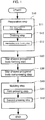
- the manufacturing method of a porous metal body 1 includes a preparation step S10, a star-shaped polygonal body forming step S20, and a molding step S40, as illustrated in Fig. 1 .
- the manufacturing method of the porous metal body 1 includes the preparation step S10 of preparing an intermediary body 32 made of a tubular wire mesh, the star-shaped polygonal body forming step S20 of forming a star-shaped polygonal body 60 by alternately forming, in a circumferential direction of the intermediary body 32, a plurality of protrusions 61 protruding radially outward and a plurality of recesses 62 receding radially inward, and the molding step S40 of inserting the star-shaped polygonal body 60 into a mold 80 that restricts an inner peripheral side and an outer peripheral side of the star-shaped polygonal body 60 and compressing the star-shaped polygonal body 60 from one side in an axial direction of the star-shaped polygonal body 60.
- the preparation step S10 is a step of knitting a metal wire 10 to form a tubular wire mesh, and forming the tubular intermediary body 32 comprising an inner peripheral portion and an outer peripheral portion from the tubular wire mesh.
- the star-shaped polygonal body forming step S20 is a step of forming the star-shaped polygonal body 60 by alternately positioning, in the circumferential direction, the plurality of recesses 61 protruding radially outward and the plurality of protrusions 62 receding radially inward, and forming the result into the intermediary body 32.
- the molding step S40 is a step of inserting the star-shaped polygonal body 60 into a space in the mold 80 configured by a core member 81 that restricts the inner peripheral side of the star-shaped polygonal body 60 and an outer peripheral wall 85 that restricts the outer peripheral side of the star-shaped polygonal body 60, the space being configured by the core member 81 and the outer peripheral wall 85, and compressing the star-shaped polygonal body 60 from one side in the axial direction of the star-shaped polygonal body 60.
- the mold 80 used in the molding step S40 is configured to be changeable to at least two forms differing in length in the axial direction thereof.
- the molding step S40 comprises at least a first pressing step S41 of compressing the star-shaped polygonal body 60 from one side in the axial direction using the mold 80 of a form having a long length in the axial direction and, after the first pressing step S41, a second pressing step S42 of further compressing the star-shaped polygonal body 60 from one side in the axial direction using the mold 80 of a form having a short length in the axial direction.
- the preparation step S10 may include a wire mesh continuous body forming step S11, a dividing step S12, and an intermediary body forming step S13.
- the wire mesh continuous body forming step S11 is a step of forming a tubular wire mesh continuous body 30 continuous in the axial direction by knitting the metal wire 10.
- the dividing step S12 is a step of dividing the wire mesh continuous body 30 into a plurality of tubular wire mesh bodies 31 having a fixed length in the axial direction thereof.
- the intermediary body forming step S13 is a step of forming the intermediary body 32 by folding a side wall portion of each of the tubular wire mesh bodies 31 in the axial direction.
- the manufacturing method of the porous metal body I may further comprise a star-shaped polygonal body compressing step S30 between the aforementioned star-shaped polygonal body forming step S20 and the molding step S40, as necessary.
- This star-shaped polygonal body compressing step S30 is a step of forming a compressed star-shaped polygonal body 60 by pressing the star-shaped polygonal body 60 formed by the star-shaped polygonal body forming step S20 from an outer side to an inner side in the radial direction, thereby compressing the star-shaped polygonal body 60 toward a center.
- this star-shaped polygonal body compressing step S30 is further provided, the compressed star-shaped polygonal body 60 is inserted into the mold 80 in the molding step S40.
- a particular effect is achieved in which a flow rate of a fluid flowing in the axial direction and the radial direction of the porous metal body 1 can be equalized in the circumferential direction of the porous metal body 1, and the strength of the porous metal body 1 can be increased.
- porous metal body 1 manufactured by the manufacturing method of the porous metal body 1 according to the present invention, followed by the details of each step of the manufacturing method of the porous metal body 1.
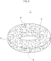
- the porous metal body 1 forms a cylindrical shape and has a cavity in the center in the radial direction. That is, the porous metal body 1 comprises an outer peripheral surface 2, an inner peripheral surface 3, and a pair of end surfaces 4, 5 that form both end portions in the axial direction.
- This porous metal body 1 is manufactured by machining a tubular wire mesh formed by knitting the metal wire 10.
- the porous metal body 1 is formed into a cylindrical shape by machining a tubular wire mesh comprising an inner peripheral surface and an outer peripheral surface and formed by knitting the metal wire 10, alternately forming in the circumferential direction the plurality of protrusions 61 protruding radially outward and the plurality of recesses 62 receding radially inward to form the star-shaped polygonal body 60, and compressing the star-shaped polygonal body 60 in the axial direction thereof while restricting the inner peripheral side and the outer peripheral side of this star-shaped polygonal body 60.
- the ring-shaped wire mesh comprises a plurality of wire mesh layers overlapping in the radial direction.
- Examples of the metal wire 10 used include a wire material made of stainless steel or mild steel.
- Examples of the stainless steel wire material include a wire material made of SUS304 or SUS316 of Japanese Industrial Standards (JIS), or the like.
- Examples of the mild steel wire material include a wire material made of SWRM6 or SWRCH6A defined by JIS, or the like.
- the material used may be plated with copper, a copper alloy, zinc, nickel, or other plating.
- the metal wire used may also be titan, nickel, aluminum, or other material.
- the porous metal body 1, being configured by a wire of such material, is heat resistant, chemical resistant, and corrosion resistant.
- the metal wire 10 is a wire material having a circular cross-sectional shape.
- a diameter of the metal wire 10 is from 0.01 mm to 3 mm inclusive.
- the material used for the metal wire 10 may be a wire material rolled so as to form an elliptical or substantially elliptical cross-sectional shape.
- the porous metal body 1 has a bulk density of from 0.5 g/cm 3 to 6.5 g/cm 3 inclusive when a stainless steel having a porosity of from 20% to 90% inclusive and a density of from 7.75 g/cm 3 to 8.06 g/cm 3 inclusive is used.
- the above porous metal body 1 can be used as a filter that captures or filters impurities contained in a fluid, a cooling member that decreases a temperature of a fluid, a muffling member that absorbs explosion sounds, a spacer used between members that constitute a structure, or the like.
- the porous metal body 1 can be used as a filter for an inflator of an airbag.
- the porous metal body 1 captures or filters impurities produced when the airbag is activated.
- the porous metal body 1 can be made to function as a muffling filter that muffles the explosion sound when the airbag is activated or as an impact absorption filter that absorbs impact or an explosion prevention filter.
- a porous metal body 1 can be used in a system different from an inflator that customarily burns powder to produce gas.
- the porous metal body 1 can be used in a heat exchange system. That is, the porous metal body 1 can be incorporated in a passage of a heat exchanging medium used in a heat exchange system, making the porous metal body 1 function as a recycling unit. In this case, the porous metal body 1 disposed between a high temperature side and a low temperature side of the heat exchange system equally transmits heat in a circumferential direction thereof, making it possible to transmit heat with high thermal conductivity.
- the porous metal body 1, as described above, can be used in locations such as a location influenced by a high load, a location influenced by a shock load, a high temperature location, or a location with severe temperature changes.
- the manufacturing method of the porous metal body 1 includes the preparation step S10, the star-shaped polygonal body forming step S20, and the molding step S40, as illustrated in Fig. 1 . Further, the manufacturing method of the porous metal body 1 may further comprise the aforementioned star-shaped polygonal body compressing step S30 between the star-shaped polygonal body forming step S20 and the molding step S40, as necessary.
- the preparation step S10 is a step of knitting the metal wire 10 to form a tubular wire mesh, and forming the tubular intermediary body 32 comprising an inner peripheral portion and an outer peripheral portion from the tubular wire mesh.
- This preparation step S10 may include the wire mesh continuous body forming step S11, the dividing step S12, and the intermediary body forming step S13, as illustrated in Fig. 1 .
- the wire mesh continuous body forming step S11 is a step of forming a tubular wire mesh continuous body 30 continuous in the axial direction by knitting the metal wire 10.
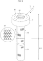
- the tubular wire mesh continuous body 30 is formed by feeding the metal wire 10 into a knitting machine 20 and knitting the fed metal wire 10 using the knitting machine 20. It should be noted that Fig. 3 schematically illustrates the knitting machine 20 for ease of explanation.
- the knitting machine 20 comprises a main body portion 21 for knitting the metal wire 10, and a guide needle 22 for guiding the fed metal wire 10 into the main body portion 21.
- the main body portion 21 comprises a hole in the center in the radial direction.
- the wire mesh continuous body 30 is fed from the hole provided in the main body portion 21.
- the wire mesh continuous body 30 forms a cylindrical shape. Further, the wire mesh continuous body 30 continues in the axial direction thereof. Note that the knitting method is not particularly limited. In the example illustrated in Fig. 3 , a wire is plain-knitted as illustrated by the enlarged view of section A to form the wire mesh continuous body 30.
- the dividing step S12 is a step of dividing the wire mesh continuous body 30 fed from the knitting machine 20 into a plurality of tubular wire mesh bodies 31 having a fixed length in the axial direction thereof.
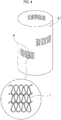
- the tubular wire mesh body 31 formed by this dividing step S12 forms a tubular shape, as illustrated in Fig. 4 .
- the interior of the tubular wire mesh body 31 is a cavity.
- the method for dividing the wire mesh continuous body 30 into the tubular wire mesh bodies 31 is not particularly limited. Examples of the method of division include a method for forming the tubular wire mesh bodies 31 by cutting the wire mesh continuous body 30 fed from the knitting machine 20 at every predetermined length using an edged tool.
- tubular wire mesh body 31 is configured by the knitting of the metal wire 10.
- the knitting method is not particularly limited, as described above.
- the tubular wire mesh body 31 illustrated in Fig. 4 is configured by plain-knitting a wire as illustrated in the enlarged view of section A.
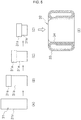
- the intermediary body forming step S13 is a step of forming the intermediary body 32 by folding a side wall portion 31a of the tubular wire mesh body 31 in the axial direction, as illustrated in Figs. 5A to 5E .
- Figs. 5A to 5E schematically illustrate the intermediary body forming step S13.
- the side wall portion 31a is folded outward a plurality of times at every fixed length in the axial direction from one end in the axial direction of the tubular wire mesh body 31, as illustrated in Figs. 5A to 5D , thereby forming the intermediary body 32 illustrated in Fig. 5E .
- the intermediary body 32 can also be formed by rolling the side wall portion 31a of the tubular wire mesh body 31 outward from one end in the axial direction of the tubular wire mesh body 31.
- the intermediary body 32 formed by this intermediary body forming step S13 is a ring-shaped wire mesh and comprises an outer peripheral portion 33 and an inner peripheral portion 34, as illustrated in Fig. 5E .
- the intermediary body 32 serving as a ring-shaped wire mesh comprises a plurality of wire mesh layers overlapping in the radial direction.
- the star-shaped polygonal body forming step S20 is a step of forming the star-shaped polygonal body 60 by alternately positioning, in the circumferential direction, the plurality of protrusions 61 protruding radially outward and the plurality of recesses 62 receding radially inward, and forming the result into the intermediary body 32.
- This star-shaped polygonal body forming step S20 includes a first type of forming the star-shaped polygonal body 60 using a device 40 illustrated in Figs. 6A and 6B , and a second type of forming the star-shaped polygonal body 60 using a device 50 illustrated in Fig. 12 .
- the star-shaped polygonal body forming step S20 of the first type is a step of forming the star-shaped polygonal body 60 by pressing a plurality of tabs 42 that are regularly spaced apart in the circumferential direction and move in the radial direction on this intermediary body 32 from the outer side in the radial direction of the intermediary body 32, as illustrated in Figs. 6A and 6B .
- the star-shaped polygonal body forming step S20 is implemented using the device 40 comprising the six tabs 42 (hereinafter simply referred to as "device 40").
- This device 40 comprises, for example, a base 41, the six tabs 42 disposed on the base 41, and a receiving portion 45 disposed on the base 41.
- the base 41 forms a disk shape.
- This base 41 is a member on which the intermediary body 32 formed as the star-shaped polygonal body 60 is placed.
- the six tabs 42 are equally disposed in the circumferential direction on the base 41.
- the tabs 42 are each arranged so that a longitudinal direction thereof is in the radial direction.
- the tabs 42 each comprise a pressing portion 43 having a tapered shape on one end side in the longitudinal direction thereof.
- the tabs 42 are each disposed so that the pressing portion 43 faces radially inward.
- the receiving portion 45 is an area that receives the intermediary body 32 pressed by the tabs 42 on the inner side of the intermediary body 32.
- the receiving portion 45 is disposed in the center of the base 41.
- the receiving portion 45 comprises at least a ring portion 46 and a partitioning portion 47 that extends radially outward from the ring portion 46.
- the partitioning portion 47 is provided in six locations in the circumferential direction. The spacing in the circumferential direction between each of the partitioning portions 47 is fixed.
- the six tabs 42 are positioned between the partitioning portions 47 of the receiving portion 45 in the circumferential direction. When the tabs 42 move radially inward, each of the pressing portions 43 of the tabs 42 is inserted between the partitioning portions 47 of the receiving portion.
- This device 40 forms the star-shaped polygonal body 60 as follows. First, as illustrated in Fig. 6A , in the device 40, the six tabs 42 are moved radially outward. The intermediary body 32 is set between the pressing portions 43 provided to each of the tabs 42, and the receiving portion 45. Once the intermediary body 32 has been set in the device 40, the tabs 42 are moved radially inward, and the pressing portions 43 are thrust against the outer peripheral portion of the intermediary body 32, pressing the intermediary body 32 from the outer side toward the inner side in the radial direction, as illustrated in Fig. 6B .
- the device 40 presses the six tabs 42 on the intermediary body 32, thereby forming the recess 62 receding from the outer side toward the inner side in the radial direction in six locations in the circumferential direction of the intermediary body 32.
- the device 40 forms sections between the sections where the tabs 42 were pressed as the protrusions 61 protruding radially outward.
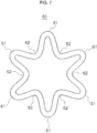
- the device 40 forms the star-shaped polygonal body 60 illustrated in Fig. 7 .
- Fig. 7 illustrates an example of the star-shaped polygonal body 60.
- This star-shaped polygonal body 60 comprises the protrusions 61 protruding radially outward in six locations in the circumferential direction. Further, the star-shaped polygonal body 60 comprises the recesses 62 receding radially inward between the protrusions 61. This recess 62 is an area formed by the pressing of the pressing portion 43 of the tab 42 as described above.
- the star-shaped polygonal body 60 formed in the star-shaped polygonal body forming step S20 is not limited to the shape comprising six protrusions 61 and six recesses 62.
- the number of the protrusions 61 and the number of the recesses 62 may be five or less or seven or more.
- the number of tabs 42 provided to the device is matched to the number of the recesses 62 and the number of the protrusions 61 of the star-shaped polygonal body 60 to be formed. For example, when a star-shaped polygonal body 60 having eight recesses 62 and eight protrusions 61 is to be formed, eight tabs 42 are provided to the device.
- the star-shaped polygonal body forming step S20 of the first type it is possible to form the recesses 62 receding radially inward in a plurality of sections where the tabs 42 were pressed, and form the protrusions 61 protruding radially outward in a plurality of sections between the sections where the tabs 42 were pressed.
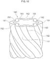
- a star-shaped polygonal body 160 illustrated in Fig. 10 may be formed from the intermediary body 32 using a device 140 illustrated in Fig. 8 (hereinafter referred to as "device 140").
- This device 140 comprises, for example, a base 141, six tabs 142 disposed on the base 141, and a receiving portion 145 disposed on the base 141.
- the base 141 forms a disk shape, for example.
- This base 141 is a member on which the intermediary body 32 formed as the star-shaped polygonal body 160 is placed.
- the six tabs 142 are equally disposed in the circumferential direction on the base 141 so that the longitudinal direction thereof is in the radial direction of the base.
- the tabs 142 each comprise a flat-plate shaped pressing portion 143 on one end side in the longitudinal direction thereof, and this pressing portion 143 faces radially inward.
- the pressing portion 143 is diagonally inclined with respect to a vertical direction. It should be noted that the vertical direction matches the axial direction of the intermediary body 32 and the axial direction of the star-shaped polygonal body 1 60.
- An inclination angle ⁇ with respect to the vertical direction of the pressing portion 143 may be set as appropriate in accordance with a length in the axial direction of the intermediary body 32, within a range of from 5 degrees to 85 degrees inclusive. That is, when the star-shaped polygonal body 160 is formed this inclination angle ⁇ is set so that protrusions 161 exist in another region in the axial direction and recesses 162 exist in one region in the axial direction in a section in the circumferential direction.
- the receiving portion 145 is an area that is disposed in the center of the base 141 and receives the intermediary body 32 pressed by the tabs 142 on the inner side of the intermediary body 32.
- the structure of the receiving portion 145 is substantially the same as that of the receiving portion 45 of the device 40 illustrated in Figs. 6A and 6B , and comprises at least a ring portion 146 and a partitioning portion 147 that extends radially outward from the ring portion 146.
- This device 140 forms the star-shaped polygonal body illustrated in Fig. 10 by thrusting the pressing portions 143 against the outer peripheral portion of the intermediary body 32 from the outer side in the radial direction of the intermediary body 32, and pressing the intermediary body 32 from the outer side toward the inner side in the radial direction. Specifically, the device 140 forms recesses 162 in the positions where the pressing portions 143 of the tabs 142 were pressed and protrusions 161 in positions between the pressing portions 143 of the tabs 142, thereby forming the star-shaped polygonal body 160.
- Fig. 10 illustrates an example of the star-shaped polygonal body 160 formed by the device 140.
- This star-shaped polygonal body 160 comprises the protrusions 161 protruding radially outward in six locations in the circumferential direction. Further, the star-shaped polygonal body 160 comprises the recesses 162 receding radially inward between the protrusions 161.
- the protrusions 161 and the recesses 162 each incline diagonally with respect to the axial direction of the star-shaped polygonal body 160.
- protrusions 161 exist in another region in the axial direction and recesses 162 exist in one region in the axial direction.
- the density in the circumferential direction is equalized.
- the porous metal body 1 formed from the star-shaped polygonal body 160 makes it possible to equalize the pressure loss of the fluid flowing in the interior of this porous metal body 1 in the circumferential direction, and equalize the strength in the circumferential direction.
- the star-shaped polygonal body 160 is formed using the tabs 142 comprising the diagonally inclined pressing portions 143.
- the star-shaped polygonal body 160 in which the protrusions 161 and the recesses 162 are diagonally inclined with respect to the axial direction may be formed by first forming the star-shaped polygonal body 60 illustrated in Fig. 7 using the device 40 illustrated in Figs. 6A and 6B , and then twisting the star-shaped polygonal body 60 in the circumferential direction.
- the star-shaped polygonal body forming step S20 of the second type is a step of forming the star-shaped polygonal body 60 by engaging a first gear 51 disposed on the outer side of the intermediary body 32 and a second gear 52 disposed on an inner side of the intermediary body 32 while moving the intermediary body 32 in the circumferential direction.
- the device 50 used in the star-shaped polygonal body forming step S20 of the second type (hereinafter simply referred to as "device 50") comprises the two gears 51, 52, as illustrated in Fig. 11 .
- Fig. 11 schematically illustrates an example of the device 50.
- the device 50 illustrated in Fig. 11 comprises the first gear 51 having a blade edge circle with a relatively large diameter, and the second gear 52 having a blade edge circle with a relatively small diameter.
- the first gear 51 is disposed on the outer side of the intermediary body 32
- the second gear 52 is disposed on the inner side of the intermediary body 32.
- This device 50 is configured so that a distance between the first gear 51 and the second gear 52 can be lengthened and shortened. However, even in a case where the distance between the first gear 51 and the second gear 52 is shortened to the maximum extent, a fixed gap is formed between the first gear 51 and the second gear 52 without the teeth of the first gear 51 and the teeth of the second gear 52 coming into contact. That is, when a tooth of the first gear 51 is positioned between two teeth of the second gear 52, a fixed gap is formed between a tooth tip of the first gear 51 and a tooth base of the second gear 52. Further, a fixed gap is also formed between a tooth surface of the first gear 51 and a tooth surface of the second gear 52.
- a fixed gap is formed between the tooth tip of the second gear 52 and the tooth base of the first gear 51, and a fixed gap is also formed between the tooth surface of the first gear 51 and the tooth surface of the second gear 52.
- the star-shaped polygonal body 60 is formed as follows by the device 50.
- the intermediary body 32 is set between the first gear 51 and the second gear 52. At this time, the second gear 52 is positioned on the inner side of the intermediary body 32.
- the first gear 51 and the second gear 52 are made to come into contact with each other, and the intermediary body 32 is sandwiched by the first gear 51 and the second gear 52.
- the side wall portion of the intermediary body 32 is pressed toward the tooth base of the second gear 52 by the tooth tips of the first gear 51, and pressed toward the tooth base of the first gear 51 by the tooth tip of the second gear 52.
- the protrusions 61 protruding radially outward and the recesses 62 receding radially inward with respect to the intermediary body 32 are formed on the intermediary body 32, as illustrated in Fig. 11 .
- the first gear 51 and the second gear 52 are rotated, and the intermediary body 32 is moved in the circumferential direction.
- the first gear 51 and the second gear 52 sandwich the intermediary body 32, the first gear 51 and the second gear 52 move the intermediary body 32 in the circumferential direction with the rotation thereof, alternately forming the protrusions 61 and the recesses 62 across a wide range in the circumferential direction of the intermediary body 32.
- the recesses 62 are formed in positions of the intermediary body corresponding to the tooth ridges of the first gear 51, and the protrusions 61 are formed in positions of the intermediary body corresponding to the tooth ridges of the second gear 52, thereby forming the star-shaped polygonal body 60.
- the protrusions 61 protruding radially outward and the recesses 62 receding radially inward are each formed in six locations in the circumferential direction, as illustrated in Fig. 7 .
- the star-shaped polygonal body 60 can be formed by simply engaging the two gears 51, 52. This makes it possible to form the star-shaped polygonal body 60 using a simple device. Further, a star-shaped polygonal body 60 having a different number of recesses 62 and protrusions 61 can be formed by simply replacing the gears with those having a different number of teeth.
- the star-shaped polygonal body 160 may be formed by engaging two helical gears 151, 152 while moving the intermediary body 32 in the circumferential direction, as illustrated in Fig. 12 .
- a device 150 used in this star-shaped polygonal body forming step S20 (hereinafter simply referred to as "device 150") comprises the two gears 151, 152, as illustrated in Fig. 12 .
- the two gears 151, 152 are helical gears in which the tooth ridges are diagonally inclined with respect to the circumferential direction of each gear.
- the device 150 illustrated in Fig. 12 comprises the first gear 151 having a blade edge circle with a relatively large diameter, and the second gear 152 having a blade edge circle with a relatively small diameter.
- the first gear 151 is disposed on the outer side of the intermediary body (not illustrated), and the second gear 152 is disposed on the inner side of the intermediary body (not illustrated).
- the device 150 sandwiches the intermediary body between the first gear 151 and the second gear 152, and rotates the first gear 151 and the second gear 152, thereby moving the intermediary body (not illustrated) in the circumferential direction and forming the star-shaped polygonal body 160 comprising the diagonally inclined protrusions 161 and recesses 162 (refer to Fig. 10 ).
- the recesses 162 are formed in positions of the intermediary body corresponding to the tooth ridges of the first gear 151
- the protrusions 161 are formed in positions of the intermediary body corresponding to the tooth ridges of the second gear 152, thereby forming the star-shaped polygonal body 160.
- the star-shaped polygonal body 160 when the star-shaped polygonal body 160 is formed by the star-shaped polygonal body forming step S20 of the second type, the star-shaped polygonal body 160 may be formed by first forming the star-shaped polygonal body 60 illustrated in Fig. 7 using the device 50 illustrated in Fig. 11 and then twisting the star-shaped polygonal body 60 in the circumferential direction.
- star-shaped polygonal body compressing step S30 will be described with reference to Fig. 13 . It should be noted that the star-shaped polygonal body compressing step S30 is a step provided as necessary, and is not required.
- the star-shaped polygonal body compressing step S30 is a step of forming the compressed star-shaped polygonal bodies 60, 160 by compressing the star-shaped polygonal body 60 formed by the star-shaped polygonal body forming step S20 from the outer side toward the inner side in the radial direction.
- a device 70 illustrated in Fig. 13 hereinafter simply referred to as "device 70" is used, for example.
- device 70 a device 70 illustrated in Fig. 13
- This device 70 comprises a circular base 75 and four arms 71 disposed on the base 75.
- the arms 71 are each disposed so that a longitudinal direction thereof is in the direction extending radially outward from a center of the base 75.
- Two of the four arms 71 are arranged on a line L1 that forms a diameter of the base 75, and are symmetrical with respect to a center of the base 75.
- the remaining two arms 71 are disposed on a line L2 orthogonal to the line L1 that forms the diameter.
- the two arms 71 are also symmetrical with respect to the center of the base 75.
- Each of the arms 71 comprises a pressing surface 72 on one end in the longitudinal direction.
- the pressing surface 72 recedes into an arc shape.
- the pressing surface 72 is a section that presses on an outer peripheral surface of the star-shaped polygonal body 60.
- the arms 71 are each disposed with this pressing surface 72 facing the center of the base 75. Then, the four arms 71 are configured to move in the radial direction.
- the star-shaped polygonal body 60 is set in the center of the base 75, and the four arms 71 are moved toward the center of the base 75, pressing each of the pressing surfaces 72 on an outer peripheral portion of the star-shaped polygonal body 60, thereby compressing the star-shaped polygonal body 60 radially inward, as illustrated in Fig. 13 .
- the compressed star-shaped polygonal body 60 is formed by the star-shaped polygonal body 60 being compressed radially inward by the arms 71.
- This star-shaped polygonal body forming step S20 makes it possible to equally distribute the space that exists in the interior of the intermediary body 32. As a result, the space that exists in the interior of the completed porous metal body 1 can be equalized in the circumferential direction. Further, this step causes plastic deformation of the wire mesh that constitutes the intermediary body 32. This makes it possible to increase the strength.
- the mold 80 configured by the core member 81 that restricts the inner peripheral side of the star-shaped polygonal bodies 60, 160 (including the compressed star-shaped polygonal bodies 60, 160) and the outer peripheral wall 85 that restricts the outer peripheral side of the star-shaped polygonal bodies 60, 160 is used.
- the molding step S40 is a step of molding the porous metal body 1 illustrated in Fig. 2 by inserting the star-shaped polygonal bodies 60, 160 into the space between the core member 81 and the outer peripheral wall 85, and compressing the star-shaped polygonal bodies 60, 160 from one side in the axial direction of the star-shaped polygonal bodies 60, 160.
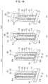
- the mold 80 used in the molding step S40 is configured to be changeable to at least two forms differing in length in the axial direction thereof, as illustrated in Figs. 14A to 14D .
- the molding step S40 comprises at least the first pressing step S41 of compressing the star-shaped polygonal body 60 from one side in the axial direction using the mold 80 of the form having a long length in the axial direction and, after the first pressing step S41, the second pressing step S42 of further compressing the star-shaped polygonal body 60 from one side in the axial direction using the mold 80 of the form having a short length in the axial direction (refer to Fig. 1 ).
- the mold 80 comprises the core member 81 and the outer peripheral wall 85, as illustrated in Figs. 14A to 14D .
- This mold 80 has a space between the core member 81 and the outer peripheral wall 85 where the star-shaped polygonal body 60 to be molded is inserted.
- a first end 80a side in the longitudinal direction of the mold 80 is open, and a second end 80b side in the longitudinal direction of the mold 80 is closed by a block 90 or the like.
- an actuator (not illustrated) is provided only on the first end 80a side in the longitudinal direction of the mold 80.
- the actuator provided only on the first end 80a side presses the star-shaped polygonal body 60 inside the mold 80 to form the porous metal body 1.
- the core member 81 that constitutes the mold 80 is configured so as to be changeable to two forms of the form having a long length in the axial direction and the form having a short length in the axial direction.
- the core member 81 comprises a core member main body portion 82 and a core member adjusting portion 83 for changing the length in the longitudinal direction of the mold 80.
- the core member 81 of the long form is a form in which the core member main body portion 82 and the core member adjusting portion 83 are connected in the longitudinal direction of the mold 80, as illustrated in Figs. 14A and 14B .
- the core member 81 of the short form is a form in which the core member adjusting portion 83 is removed from the core member 81, as illustrated in Figs. 14C and 14D .
- the outer peripheral wall 85 that constitutes the mold 80 is configured so as to be changeable to two forms of the form having a long length in the axial direction and the form having a short length in the axial direction, in the same way as the core member 81.
- the outer peripheral wall 85 comprises an outer peripheral wall main body portion 86 and an outer peripheral wall adjusting portion 87.
- the outer peripheral wall 85 of the long form is a form in which the outer peripheral wall main body portion 86 and the outer peripheral wall adjusting portion 87 are connected in the longitudinal direction of the mold 80, as illustrated in Figs. 14A and 14B .
- the outer peripheral wall 85 of the short form is a form in which the outer peripheral wall adjusting portion 87 is removed from the outer peripheral wall 85, as illustrated in Figs. 14C and 14D .
- the molding step S40 The details of the molding step S40 will now be described with reference to Figs. 14A to 14D .
- the first pressing step S41 illustrated in Figs. 14A and 14B is performed, followed by the second pressing step S42 illustrated in Figs. 14C and 14D .
- first the core member main body portion 82 and the core member adjusting portion 83 are connected in the axial direction, and the outer peripheral wall main body portion 86 and the outer peripheral wall adjusting portion 87 are connected in the axial direction, thereby forming the mold 80 having the long form, as illustrated in Fig. 14A .
- first end 80a side in the axial direction of the mold 80 is open while the second end 80b in the axial direction of the mold 80 is closed by the block 90.
- a first auxiliary member 101, the star-shaped polygonal body 60, and a second auxiliary member 102 are inserted, in that order, into the interior of the mold 80 having this form. That is, as viewed from the second end 80b side of the mold 80, the first auxiliary member 101, the star-shaped polygonal body 60, and the second auxiliary member 102 are disposed, in that order, in the interior of the mold 80.
- the actuator presses the star-shaped polygonal body 60 by pressing the first auxiliary member 101, the star-shaped polygonal body 60, and the second auxiliary member 102 in the interior of the mold 80 from the first end 80a side in the axial direction of the mold 80 toward the block 90.
- a third auxiliary member 103 is inserted into the interior of the mold 80 from the first end 80a side in the axial direction of the mold 80, and is disposed on the second auxiliary member 102, as illustrated in Fig. 14B .
- the actuator (not illustrated) further presses the star-shaped polygonal body 60 by pressing the first auxiliary member 101, the star-shaped polygonal body 60, the second auxiliary member 102, and the third auxiliary member 103 in the interior of the mold 80 from the first end 80a side in the axial direction of the mold 80 toward the block 90.
- the second pressing step S42 is performed.
- the second pressing step S42 first the core member adjusting portion 83 and the outer peripheral wall adjusting portion 87 are removed from the mold 80, as illustrated in Fig. 14C .
- the mold 80 is in the short form made of the core member main body portion 82 and the outer peripheral wall main body portion 86.
- the first auxiliary member 101 protrudes from the mold 80 on the second end 80b side in the axial direction of the mold 80 where the block 90 is disposed.
- a pressing jig 104 is made to cover the first end 80a side in the axial direction of the mold 80, as illustrated in Fig. 14C .
- a lower end surface surrounding this pressing jig 104 is thrust against an end surface on the first end 80a side of the mold 80, and a tip end of the core member 81 is inserted into the interior in a center of the pressing jig 104.
- the actuator presses the mold 80 from the first end 80a side in the axial direction of the mold 80, from above the pressing jig 104 toward the block 90.
- the mold 80 is pressed toward the block 90, thereby pressing the star-shaped polygonal body 60.
- the outer peripheral surface is restricted by the outer peripheral wall 85 and is formed into a circular shape along an inner surface of the outer peripheral wall 85, Further, the inner peripheral surface is restricted by the core member 81 and is formed into a circular shape.
- the star-shaped polygonal body 60 is molded into the porous metal body 1 having a cylindrical shape illustrated in Fig. 2 .
- the mold 80 is configured by the main body portions 82, 86 and the adjusting portions 83, 87 as described above, and thus the length in the axial direction of the mold 80 is changed by removing the adjusting portions 83, 87 from the mold 80.
- the star-shaped polygonal body 60 is pressed from only one side in the axial direction of the mold 80, making it possible to exert a compressing action equivalent to pressing the star-shaped polygonal body 60 from both sides in the axial direction of the mold 80 on the star-shaped polygonal body 60.
- the molding step S40 is performed using the mold 80 that allows the length in the axial direction to be changed to two forms as an example. Nevertheless, the molding step S40 can also be performed using a mold that allows the length in the axial direction to be changed to three or more forms.
- the porous metal body 1 manufactured by the manufacturing method of the porous metal body 1 that includes the above steps has a high strength. Further, pores that exist in the interior of the porous metal body 1 are equally distributed in the circumferential direction. As a result, when a fluid flows in the axial direction and the radial direction, the fluid flows equally in the circumferential direction of the porous metal body 1.
- the porous metal body 1 fabricated by the manufacturing method of the porous metal body 1 according to the present invention and a conventionally used porous metal body were subjected to a pressure loss verification test and a compression strength verification test, and compared.
- the conventionally used porous metal body is a porous metal body completed by pressing an intermediary body formed midway through the manufacturing method of the porous metal body 1 of the present invention, as is. That is, the conventionally used porous metal body is completed without a star-shaped polygonal body forming step.
- Example 1 is a porous metal body obtained by fabricating the metal wire 10 made of a white annealed iron wire having a 0.36-mm diameter through the wire mesh continuous body forming step, the dividing step, the intermediary body forming step, the star-shaped polygonal body forming step, and the molding step.
- the metal wire 10 was plain-knitted to form a wire mesh continuous body.
- the length in the axial direction of the porous metal body was 10 mm.
- Example 2 is a porous metal body obtained by fabricating the metal wire 10 made of a white annealed iron wire having a 0.70-mm diameter using the same manufacturing method as that in Example 1.
- the length in the axial direction of the porous metal body was 10 mm.
- Comparative example 1 is a porous metal body obtained by fabricating the same metal wire 10 as that in Example 1 through the wire mesh continuous body forming step, the dividing step, the intermediary body forming step, and the molding step.
- the metal wire 10 was plain-knitted to form a wire mesh continuous body.
- the length in the axial direction of the porous metal body was 10 mm.
- Comparative example 2 is a porous metal body obtained by fabricating the metal wire 10 made of a white annealed iron wire having a 0.70-mm diameter using the same manufacturing method as that in Comparative example 1.
- the length in the axial direction of the porous metal body was 10 mm.
- a pressure loss verification test was performed for a case in which fluid was made to flow in a radial direction of the test sample, and a case in which fluid was made to flow in an axial direction of the test sample.
- the radial direction verification test air was circulated from the inner peripheral side to the outer peripheral side of the test sample, and the pressure loss was measured.
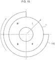
- the verification test was performed by circulating air at flow rates of 50 liters/minute, 70 liters/minute, and 100 liters/minute. Further, the verification test, as illustrated in Fig. 15 , divided the circumferential direction of the test sample into four regions I, II, III, and IV, and measured the pressure loss in each of the regions I, II, III, and IV.
- the verification test was performed by blocking end surfaces on both sides in the axial direction of the porous metal body, inserting a jig 110 having a ring shape with one-quarter section in the circumferential direction omitted around the outer periphery of the test sample, and rotating the jig 110 one-quarter of a turn in the circumferential direction each time. It should be noted that the verification test was conducted on two Examples and two Comparative examples.
- the evaluation was performed by calculating an average value of the measurement results of four locations in each test sample, and finding the maximum percentage of variance with respect to the average value.
- the maximum percentage of variance refers to either the maximum variance on the positive side with respect to the average value or the maximum variance on the negative side with respect to the average value, whichever is largest.
- Table 1 shows the test results of the verification test.
- a first sample of Example 2 as shown in Table 1, exhibited variances with respect to the average value of 14.6% at a flow rate of 50 liters/minute, 12.0% at a flow rate of 70 liters/minute, and 11.6% at a flow rate of 100 liters/minute.
- a second sample of Example 2 exhibited variances with respect to the average value of 7.2% at a flow rate of 50 liters/minute, 8.8% at a flow rate of 70 liters/minute, and 11.0% at a flow rate of 100 liters/minute.
- the averages of the first sample and the second sample were 10.9% at a flow rate of 50 liters/minute, 10.4% at a flow rate of 70 liters/minute, and 11.3% at a flow rate of 100 liters/minute.
- a first sample of Comparative example 1 exhibited variances with respect to the average value of 37.5% at a flow rate of 50 liters/minute, 38.1% at a flow rate of 70 liters/minute, and 33.8% at a flow rate of 100 liters/minute.
- a second sample of Comparative example 1 exhibited variances with respect to the average value of 27.0% at a flow rate of 50 liters/minute, 27.2% at a flow rate of 70 liters/minute, and 26.8% at a flow rate of 100 liters/minute.
- the averages of the first sample and the second sample were 32.2% at a flow rate of 50 liters/minute, 32.6% at a flow rate of 70 liters/minute, and 30.3% at a flow rate of 100 liters/minute.
- a first sample of Comparative example 2 exhibited variances with respect to the average value of 38.3% at a flow rate of 50 liters/minute, 34.3% at a flow rate of 70 liters/minute, and 34.5% at a flow rate of 100 liters/minute.
- a second sample of Comparative example 2 exhibited variances with respect to the average value of 22.0% at a flow rate of 50 liters/minute, 26.1% at a flow rate of 70 liters/minute, and 27.8% at a flow rate of 100 liters/minute.
- the averages of the first sample and the second sample were 30.1% at a flow rate of 50 liters/minute, 30.2% at a flow rate of 70 liters/minute, and 31.2% at a flow rate of 100 liters/minute.
- the porous metal body 1 fabricated by the manufacturing method of the porous metal body 1 of the present invention has less variance in pressure loss in the circumferential direction when fluid flows in the radial direction than that of the conventional porous metal body.
- the axial direction verification test air was circulated from one end surface to the other end surface in the axial direction of the test sample, and the pressure loss was measured.
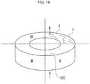
- the verification test was performed by circulating air at flow rates of 50 liters/minute, 70 liters/minute, and 100 liters/minute. Further, the verification test, as illustrated in Fig. 16 , divided the circumferential direction of the test sample into four regions I, II, III, and IV, and measured the pressure loss in each of the regions I, II, III, and IV.
- the verification test was performed by blocking an outer peripheral surface and an inner peripheral surface of the porous metal body, blocking a three-quarter section in the circumferential direction of both end surfaces in the axial direction using the jig 120 having a ring shape with one-quarter section in the circum ferential direction omitted, and rotating the jig 120 one-quarter of a turn in the circumferential direction each time. It should be noted that the verification test was conducted on two Examples and two Comparative examples.
- the evaluation was performed by calculating an average value of the measurement results of four locations in each test sample, and finding the maximum percentage of variance with respect to the average value.
- the maximum percentage of variance refers to either the maximum variance on the positive side with respect to the average value or the maximum variance on the negative side with respect to the average value, whichever is largest.
- Table 2 shows the test results of the verification test.
- a first sample of Example 1 as shown in Table 2, exhibited variances with respect to the average value of 11.9% at a flow rate of 50 liters/minute, 16.3% at a flow rate of 70 liters/minute, and 14.9% at a flow rate of 100 liters/minute.
- a second sample of Example 1 exhibited variances with respect to the average value of 13.9% at a flow rate of 50 liters/minute, 8.0% at a flow rate of 70 liters/minute, and 7.6% at a flow rate of 100 liters/minute.
- the averages of the first sample and the second sample were 12.9% at a flow rate of 50 liters/minute, 12.2% at a flow rate of 70 liters/minute, and 11.2% at a flow rate of 100 liters/minute.
- a first sample of Example 2 as shown in Table 2, exhibited variances with respect to the average value of 11.5% at a flow rate of 50 liters/minute, 16.5% at a flow rate of 70 liters/minute, and 13.4% at a flow rate of 100 liters/minute.
- a second sample of Example 2 exhibited variances with respect to the average value of 20.8% at a flow rate of 50 liters/minute, 8.9% at a flow rate of 70 liters/minute, and 8.8% at a flow rate of 100 liters/minute.
- the averages of the first sample and the second sample were 16.2% at a flow rate of 50 liters/minute, 12.7% at a flow rate of 70 liters/minute, and 11.1% at a flow rate of 100 liters/minute.
- a first sample of Comparative example 1 exhibited variances with respect to the average value of 37.4% at a flow rate of 50 liters/minute, 37.4% at a flow rate of 70 liters/minute, and 35.9% at a flow rate of 100 liters/minute.
- a second sample of Comparative example 1 exhibited variances with respect to the average value of 26.7% at a flow rate of 50 liters/minute, 27.3% at a flow rate of 70 liters/minute, and 26.3% at a flow rate of 100 liters/minute.
- the averages of the first sample and the second sample were 32.1% at a flow rate of 50 liters/minute, 32.4% at a flow rate of 70 liters/minute, and 31.1% at a flow rate of 100 liters/minute.
- a first sample of Comparative example 2 exhibited variances with respect to the average value of 44.9% at a flow rate of 50 liters/minute, 42.5% at a flow rate of 70 liters/minute, and 52.0% at a flow rate of 100 liters/minute.
- a second sample of Comparative example 2 exhibited variances with respect to the average value of 23.1% at a flow rate of 50 liters/minute, 26.6% at a flow rate of 70 liters/minute, and 28.5% at a flow rate of 100 liters/minute.
- the averages of the first sample and the second sample were 34.0% at a flow rate of 50 liters/minute, 34.6% at a flow rate of 70 liters/minute, and 40.3% at a flow rate of 100 liters/minute.
- the porous metal body 1 fabricated by the manufacturing method of the porous metal body 1 of the present invention has less variance in pressure loss in the circumferential direction when fluid flows in the axial direction than that of the conventional porous metal body.
- the test sample was compressed in the axial direction using a Tensilon universal testing machine (RTG-1310 manufactured by A&D), and the relationship between compression load and displacement was measured.
- the verification test was performed with a speed for compressing the test sample set to 5 mm/minute, and the load limit set to 5000 newtons. It should be noted that the verification test was conducted once on each of the Examples 1 and 2 and Comparative examples 1 and 2.
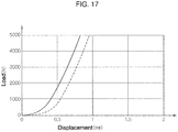
- the graph shown in Fig. 17 indicates the test results of Example 1 and Comparative example 1.
- the horizontal axis of the graph indicates displacement, and the vertical axis of the graph indicates compression load. Further, the solid line indicates Example 1, and the dashed line indicates Comparative example 1.
- Example 1 as indicated by the solid line in the graph in Fig. 17 , exhibited a displacement of less than 0.5 mm even at a load of 1000 newtons, and approximately 0.5 mm at a load of 2000 newtons. Then, the displacement was approximately 0.82 mm at a load of 5000 newtons.
- Comparative example 1 as indicated by the dashed line in the graph in Fig. 17 , exhibited a greater overall shift to the right than that of the graph of Example 1. Specifically, at a load of 1000 newtons, the displacement already reached approximately 0.5 mm. Further, the displacement was approximately 0.94 mm at a load of 5000 newtons.
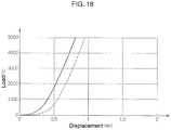
- the graph shown in Fig. 18 indicates the test results of Example 2 and Comparative example 2.
- the horizontal axis of the graph indicates displacement, and the vertical axis of the graph indicates compression load. Further, the solid line indicates Example 2, and the dashed line indicates Comparative example 2.
- Example 2 as indicated by the solid line in the graph in Fig. 18 , exhibited a displacement of less than 0.5 mm even at a load of 1000 newtons, and approximately 0.5 mm at a load of 2000 newtons. Then, the displacement was approximately 0.80 mm at a load of 5000 newtons.
- Comparative example 2 as indicated by the dashed line in the graph in Fig. 18 , exhibited a greater overall shift to the right than that of the graph of Example 2. Specifically, at a load of 1000 newtons, the displacement already reached approximately 0.5 mm. Further, the displacement was approximately 0.94 mm at a load of 5000 newtons.
- the porous metal body 1 fabricated by the manufacturing method of the porous metal body 1 according to the present invention and the conventional porous metal body were compressed under the same conditions, the porous metal body 1 fabricated by the manufacturing method of the porous metal body 1 of the present invention exhibited less displacement and greater strength than the conventional porous metal body.
- the differences between the two were studied by cutting the porous metal body 1 manufactured by the porous metal body manufacturing method according to the present invention and the porous metal body manufactured by the conventional manufacturing method, and enlarging and closely examining the cross sections under a microscope.
- the practical method for examining the internal structure of the porous metal body without excessive economic expenditure or excessive time requirements was to cut the porous metal body and enlarge and examine the cross section under a microscope.
Description
- The present invention relates to a porous metal body manufacturing method, and more specifically relates to a porous metal body manufacturing method wherein a tubular body formed by knitting a metal wire is machined.
- A porous body is used in various applications, such as filters, cooling members, and muffling members. When a porous body is used as a filter, for example, the porous body filters or captures impurities contained in a fluid.
- An airbag system is an example of a system that uses a porous body as a filter. The airbag system comprises an inflator (gas producing device) that produces gas by burning a powder. The airbag system is a system that inflates an airbag by supplying the gas produced by the inflator to an airbag incorporated into a steering wheel or the like. The porous body used in such an airbag system captures combustion remnants produced when the inflator burns the powder, cools the produced gas, and thus prevents the airbag from becoming damaged. Methods for manufacturing this porous body have been proposed in various literature to date.
- The manufacturing method proposed in Patent Document I is a method for manufacturing a porous body from a wire mesh body formed by plain-knitting a metal wire. This manufacturing method comprises the steps of forming a preliminary tubular wire mesh body using a tubular wire mesh body formed by plain-knitting a metal wire, molding a small-diameter tubular wire mesh body obtained by reducing a diameter of this preliminary tubular wire mesh body by a drawing process, cutting the small-diameter tubular wire mesh body to a predetermined length, compressing the cut small-diameter tubular wire mesh body in a longitudinal direction and molding the wire mesh body into a cylindrical intermediary molded wire mesh body, and further compressing the cylindrical intermediary molded wire mesh body in the longitudinal direction and molding the wire mesh body into a cylindrical molded wire mesh body.
- The manufacturing method proposed in
Patent Document 2 comprises the steps of plain-knitting a metal wire to form a cylindrical wire mesh, forming a hollow cylindrical wire mesh body by winding a band-shaped body obtained by folding this wire mesh around a core member, and compressing this cylindrical wire mesh body by applying pressure from both sides in an axial direction thereof.Patent Document 3, which represents the closest prior art forindependent claim 1, discloses a porous metal body manufacturing method, comprising at least: a preparation step of preparing an intermediary body made of a tubular wire mesh (by knitting and folding); and a molding step of inserting the intermediary body into a mold that restricts an inner peripheral side and an outer peripheral side of the intermediary body and compressing the intermediary body from one side in the axial direction of the intermediary body. -
- Patent Document 1: Japanese Laid-Open Patent Application No.
H11-197422 - Patent Document 2: Japanese Laid-Open Patent Application No.
H11-244629 - Patent Document 3: American Patent No.
US 5,849,054 - Nevertheless, the porous bodies manufactured by the manufacturing methods proposed in
Patent Document 1 andPatent Document 2 are merely manufactured by simply compressing a tubular wire mesh in the longitudinal direction (axial direction) thereof. As a result, pores that exist in the interior of the porous body may not be equally distributed in a circumferential direction. With a porous body in which the pores are not equally distributed in the circumferential direction, when a fluid is made to flow from one side to the other side in an axial direction or in a radial direction of the porous body, the fluid may not flow equally in the circumferential direction of the porous body. Further, without the pores in the interior of the porous body being equally distributed, it is difficult to manufacture a porous body having high strength. - The present invention was designed to solve the above problems, and it is therefore an object of the present invention to provide a porous metal body manufacturing method by which a flow rate of a fluid flowing in an axial direction and a radial direction of a porous metal body can be equalized in a circumferential direction of the porous metal body and a strength of the porous metal body can be increased.
- A porous metal body manufacturing method according to the present invention for solving the above-described problems comprises at least a preparation step of preparing an intermediary body made of a tubular wire mesh, a star-shaped polygonal body forming step of forming a star-shaped polygonal body by alternately forming, in a circumferential direction of the intermediary body, a plurality of protrusions protruding radially outwards and a plurality of recesses receding radially inwards, and a molding step of inserting the star-shaped polygonal body into a mold that restricts an inner peripheral side and an outer peripheral side of the star-shaped polygonal body and compressing the star-shaped polygonal body from one side in an axial direction of the star-shaped polygonal body
- According to this invention, the porous metal body is manufactured through each step described above, making it possible to manufacture a porous metal body having high strength, and equalize a flow rate of a fluid flowing in the axial direction and the radial direction of the porous metal body in the circumferential direction of the porous metal body. In particular, through the star-shaped polygonal body forming step described above, pores between metal wires that exist within the wire mesh constituting the intermediary body are equally distributed in the circumferential direction. This makes it possible to equally distribute the pores that exist in the interior of the completed porous metal body in the circumferential direction. Further, this star-shaped polygonal body forming step causes plastic deformation of the wire mesh constituting the intermediary body. As a result, the strength of the completed porous metal body is improved.
- In the porous metal body manufacturing method according to the present invention, the preparation step is a step of knitting a metal wire to form a tubular wire mesh, and forming a tubular intermediary body comprising an inner peripheral portion and an outer peripheral portion from the wire mesh. The mold used in the molding step is configured by a core member that restricts an inner peripheral side of the star-shaped polygonal body, and an outer peripheral wall that restricts an outer peripheral side of the star-shaped polygonal body, and is configured to be changeable to at least two forms differing in length in an axial direction thereof. The molding step comprises at least a first pressing step of compressing the star-shaped polygonal body from one side in the axial direction using the mold of a form having a long length in the axial direction and, after the first pressing step, a second pressing step of further compressing the star-shaped polygonal body from one side in the axial direction using the mold of a form having a short length in the axial direction.
- According to this invention, the tubular wire mesh prepared in the preparation step described above is formed by knitting the wire, making it possible to form a wire mesh with excellent machinability. Further, in the molding step, the star-shaped polygonal body is inserted into the mold comprising the core member and the outer peripheral wall as described above, making it possible to reliably restrict the inner peripheral side and the outer peripheral side of the star-shaped polygonal body. Further, the molding step described above includes the first pressing step and the second pressing step, making it possible to exert a compressing action equivalent to pressing the star-shaped polygonal body from both sides in the axial direction of the mold on the star-shaped polygonal body by pressing the star-shaped polygonal body from only one side in the axial direction of the mold in both the first pressing step and the second pressing step. That is, by simply providing an actuator for pressing the star-shaped polygonal body on only one side in the axial direction of the mold, it is possible to achieve the same action as that when an actuator for pressing the star-shaped polygonal body is provided on both sides in the axial direction of the mold.
- In the porous metal body manufacturing method according to the present invention, the star-shaped polygonal body forming step is a step of forming the star-shaped polygonal body by pressing a plurality of tabs that are regularly spaced apart in the circumferential direction and move in the radial direction on the intermediary body from an outer side in a radial direction of the intermediary body, thereby forming the recesses in positions where the tabs were pressed and forming the protrusions in positions between the tabs.
- According to this invention, the star-shaped polygonal body forming step is performed as described above, making it possible to form recesses receding radially inward in a plurality of sections where the tabs were pressed, and form protrusions protruding radially outward in a plurality of sections between the sections where the tabs were pressed. This makes it possible to efficiently form the star-shaped polygonal body by pressing the plurality of tabs on the intermediary body all at once.
- In the porous metal body manufacturing method according to the present invention, the star-shaped polygonal body forming step is a step of forming the star-shaped polygonal body by engaging a first gear disposed on an outer side of the intermediary body and a second gear disposed on an inner side of the intermediary body while moving the intermediary body in the circumferential direction, thereby forming the recesses in positions of the intermediary body corresponding to tooth ridges of the first gear and forming the protrusions in positions of the intermediary body corresponding to tooth ridges of the second gear.
- According to this invention, the star-shaped polygonal body forming step is performed as described above, making it possible to form the star-shaped polygonal body by simply engaging two gears. This makes it possible to form the star-shaped polygonal body using a simple device. Further, a star-shaped polygonal body having a different number of recesses and protrusions can be formed by simply replacing the gears with those having a different number of teeth.
- In the porous metal body manufacturing method according to the present invention, the star-shaped polygonal body forming step is a step of forming the star-shaped polygonal body by diagonally inclining the plurality of protrusions and the plurality of recesses with respect to the axial direction of the intermediary body.
- According to this invention, the star-shaped polygonal body is formed by diagonally inclining the plurality of protrusions and the plurality of recesses with respect to the axial direction of the intermediary body in the star-shaped polygonal body forming step, and thus in a section in the circumferential direction, the protrusions exist in one region in the axial direction and the recesses exist in another region in the axial direction when the star-shaped polygonal body is formed. As a result, when the formed star-shaped polygonal body is viewed in a planar view, the protrusions overlap with the positions of the recesses in the circumferential direction of the star-shaped polygonal body, and a density of the star-shaped polygonal body becomes equal in the circumferential direction. This makes it possible to equalize the density in the circumferential direction of the porous metal body completed through the molding step.
- In the porous metal body manufacturing method according to the present invention, the core member and the outer peripheral wall each comprise a main body portion and a length adjusting portion removable from the main body portion. In the first pressing step, the star-shaped polygonal body is compressed using the mold made of the core member and the outer peripheral wall with the length adjusting portions assembled with the main body portions. In the second pressing step, the star-shaped polygonal body is compressed using the mold made of the core member and the outer peripheral wall with the length adjusting portions removed from the main body portions.
- According to this invention, the mold used in the molding step is configured as described above, making it possible to press the star-shaped polygonal body from one side in the axial direction of the mold having a long form in the first pressing step, and press the star-shaped polygonal body from one side in the axial direction of the mold having a short form in the second pressing step, by changing the form of the mold.
- In the porous metal body manufacturing method according to the present invention, the preparation step may include a wire mesh continuous body forming step of forming a tubular wire mesh continuous body continuous in the axial direction by knitting a metal wire, a dividing step ofdividing the wire mesh continuous body into a plurality of tubular wire mesh bodies having a fixed length in the axial direction, and an intermediary body forming step of forming the intermediary body by folding a side wall portion of the tubular wire mesh body in the axial direction.
- According to this invention, the preparation step for preparing the intermediary body includes the wire mesh continuous body forming step, the dividing step, and the intermediary body forming step, making it possible to efficiently form the intermediary body.
- The porous metal body manufacturing method according to the present invention may further comprise a star-shaped polygonal body compressing step of forming a compressed star-shaped polygonal body by pressing the star-shaped polygonal body formed by the star-shaped polygonal body forming step from an outer side to an inner side in the radial direction, thereby compressing the star-shaped polygonal body toward a center. In the molding step, the compressed star-shaped polygonal body can be inserted into the mold.
- According to this invention, the star-shaped polygonal body compressing step is provided between the star-shaped polygonal body forming step and the molding step, making it possible to shorten a length of the protrusions of the star-shaped polygonal body that protrude radially. When the star-shaped polygonal body is compressed, shortening the length of the protrusions, the distribution of the pores that exist inside the protrusions is equalized by the compression of the protrusions. Further, it is possible to compress the star-shaped polygonal body radially inwards on the whole.
- According to the present invention, it is possible to equalize, in a circumferential direction of a porous metal body, a flow rate of a fluid flowing in an axial direction and a radial direction of the porous metal body, and increase a strength of the porous metal body.
-
-
Fig. 1 is a flowchart illustrating one embodiment of a porous metal body manufacturing method according to the present invention. -
Fig. 2 is a perspective view of a porous metal body of one embodiment manufactured by the porous metal body manufacturing method according to the present invention. -
Fig. 3 is an explanatory view for explaining a wire mesh continuous body forming step and a dividing step included in a preparation step. -
Fig. 4 is a perspective view illustrating an example of a tubular wire mesh body formed in the dividing step. -
Figs. 5A to 5E are explanatory views for explaining an intermediary body forming step included in a preparation step. -
Figs. 6A and 6B are explanatory views for explaining a star-shaped polygonal body forming step of a first type. -
Fig. 7 is a plan view illustrating an example of a star-shaped polygonal body. -
Fig. 8 is an explanatory view for explaining the star-shaped polygonal body forming step of the first type of a form different from that of the star-shaped polygonal body forming step illustrated inFigs. 6A and 6B . -
Fig. 9 is an explanatory view for explaining a pressing portion that constitutes a tab of the device illustrated inFig. 8 . -
Fig. 10 is a perspective view illustrating an example of the star-shaped polygonal body of a form different from that of the star-shaped polygonal body illustrated inFig. 7 . -
Fig. 11 is an explanatory view for explaining the star-shaped polygonal body forming step of a second type. -
Fig. 12 is a perspective view illustrating a helical gear of a device that uses a helical gear, used in the star-shaped polygonal body forming step of the second type. -
Fig. 13 is an explanatory view for explaining a star-shaped polygonal body compressing step. -
Figs. 14A to 14D are explanatory views for explaining a molding step. -
Fig. 15 is an explanatory view for explaining a form of a test sample when a fluid is made to flow in a radial direction and a pressure loss verification test is performed. -
Fig. 16 is an explanatory view for explaining a form of a test sample when a fluid is made to flow in an axial direction and a pressure loss verification test is performed. -
Fig. 17 is a graph showing the results of a compression strength verification test. -
Fig. 18 is a graph showing the results of a compression strength verification test. - The following describes embodiments of the present invention with reference to the drawings. Note that the technical scope of the present invention is not limited to only the following descriptions and drawings.
- The manufacturing method of a
porous metal body 1 according to the present invention includes a preparation step S10, a star-shaped polygonal body forming step S20, and a molding step S40, as illustrated inFig. 1 . Specifically, the manufacturing method of theporous metal body 1 includes the preparation step S10 of preparing anintermediary body 32 made of a tubular wire mesh, the star-shaped polygonal body forming step S20 of forming a star-shapedpolygonal body 60 by alternately forming, in a circumferential direction of theintermediary body 32, a plurality ofprotrusions 61 protruding radially outward and a plurality ofrecesses 62 receding radially inward, and the molding step S40 of inserting the star-shapedpolygonal body 60 into amold 80 that restricts an inner peripheral side and an outer peripheral side of the star-shapedpolygonal body 60 and compressing the star-shapedpolygonal body 60 from one side in an axial direction of the star-shapedpolygonal body 60. - The preparation step S10 is a step of knitting a
metal wire 10 to form a tubular wire mesh, and forming the tubularintermediary body 32 comprising an inner peripheral portion and an outer peripheral portion from the tubular wire mesh. The star-shaped polygonal body forming step S20 is a step of forming the star-shapedpolygonal body 60 by alternately positioning, in the circumferential direction, the plurality ofrecesses 61 protruding radially outward and the plurality ofprotrusions 62 receding radially inward, and forming the result into theintermediary body 32. The molding step S40 is a step of inserting the star-shapedpolygonal body 60 into a space in themold 80 configured by acore member 81 that restricts the inner peripheral side of the star-shapedpolygonal body 60 and an outerperipheral wall 85 that restricts the outer peripheral side of the star-shapedpolygonal body 60, the space being configured by thecore member 81 and the outerperipheral wall 85, and compressing the star-shapedpolygonal body 60 from one side in the axial direction of the star-shapedpolygonal body 60. Themold 80 used in the molding step S40 is configured to be changeable to at least two forms differing in length in the axial direction thereof. - The molding step S40 comprises at least a first pressing step S41 of compressing the star-shaped
polygonal body 60 from one side in the axial direction using themold 80 of a form having a long length in the axial direction and, after the first pressing step S41, a second pressing step S42 of further compressing the star-shapedpolygonal body 60 from one side in the axial direction using themold 80 of a form having a short length in the axial direction. - It should be noted that the preparation step S10 may include a wire mesh continuous body forming step S11, a dividing step S12, and an intermediary body forming step S13. The wire mesh continuous body forming step S11 is a step of forming a tubular wire mesh
continuous body 30 continuous in the axial direction by knitting themetal wire 10. The dividing step S12 is a step of dividing the wire meshcontinuous body 30 into a plurality of tubularwire mesh bodies 31 having a fixed length in the axial direction thereof. The intermediary body forming step S13 is a step of forming theintermediary body 32 by folding a side wall portion of each of the tubularwire mesh bodies 31 in the axial direction. - Further, the manufacturing method of the porous metal body I may further comprise a star-shaped polygonal body compressing step S30 between the aforementioned star-shaped polygonal body forming step S20 and the molding step S40, as necessary. This star-shaped polygonal body compressing step S30 is a step of forming a compressed star-shaped
polygonal body 60 by pressing the star-shapedpolygonal body 60 formed by the star-shaped polygonal body forming step S20 from an outer side to an inner side in the radial direction, thereby compressing the star-shapedpolygonal body 60 toward a center. When this star-shaped polygonal body compressing step S30 is further provided, the compressed star-shapedpolygonal body 60 is inserted into themold 80 in the molding step S40. - According to the manufacturing method of the
porous metal body 1 according to the present invention comprising the above steps, a particular effect is achieved in which a flow rate of a fluid flowing in the axial direction and the radial direction of theporous metal body 1 can be equalized in the circumferential direction of theporous metal body 1, and the strength of theporous metal body 1 can be increased. - The following describes the
porous metal body 1 manufactured by the manufacturing method of theporous metal body 1 according to the present invention, followed by the details of each step of the manufacturing method of theporous metal body 1. - The
porous metal body 1, as illustrated inFig. 2 , forms a cylindrical shape and has a cavity in the center in the radial direction. That is, theporous metal body 1 comprises an outerperipheral surface 2, an innerperipheral surface 3, and a pair ofend surfaces 4, 5 that form both end portions in the axial direction. - This
porous metal body 1 is manufactured by machining a tubular wire mesh formed by knitting themetal wire 10. Specifically, theporous metal body 1 is formed into a cylindrical shape by machining a tubular wire mesh comprising an inner peripheral surface and an outer peripheral surface and formed by knitting themetal wire 10, alternately forming in the circumferential direction the plurality ofprotrusions 61 protruding radially outward and the plurality ofrecesses 62 receding radially inward to form the star-shapedpolygonal body 60, and compressing the star-shapedpolygonal body 60 in the axial direction thereof while restricting the inner peripheral side and the outer peripheral side of this star-shapedpolygonal body 60. Further, the ring-shaped wire mesh comprises a plurality of wire mesh layers overlapping in the radial direction. - Examples of the
metal wire 10 used include a wire material made of stainless steel or mild steel. Examples of the stainless steel wire material include a wire material made of SUS304 or SUS316 of Japanese Industrial Standards (JIS), or the like. Examples of the mild steel wire material include a wire material made of SWRM6 or SWRCH6A defined by JIS, or the like. When a mild steel wire material is used as themetal wire 10, the material used may be plated with copper, a copper alloy, zinc, nickel, or other plating. However, in addition to the above materials, the metal wire used may also be titan, nickel, aluminum, or other material. Theporous metal body 1, being configured by a wire of such material, is heat resistant, chemical resistant, and corrosion resistant. - The
metal wire 10 is a wire material having a circular cross-sectional shape. A diameter of themetal wire 10 is from 0.01 mm to 3 mm inclusive. However, the material used for themetal wire 10 may be a wire material rolled so as to form an elliptical or substantially elliptical cross-sectional shape. - With the machining of the tubular wire mesh made of the
metal wire 10 described above, theporous metal body 1 has a bulk density of from 0.5 g/cm3 to 6.5 g/cm3 inclusive when a stainless steel having a porosity of from 20% to 90% inclusive and a density of from 7.75 g/cm3 to 8.06 g/cm3 inclusive is used. It should be noted that "porosity" is the ratio of the volume of all the gaps in a product to the total volume of the product, which can be expressed as [(Specific gravity of material - Product density) / Specific gravity of material] x 100, and "bulk density" is the mass per unit volume obtained by dividing the product weight by the product volume, which can be expressed as Mass per unit volume = Product weight / Product volume. - The above
porous metal body 1 can be used as a filter that captures or filters impurities contained in a fluid, a cooling member that decreases a temperature of a fluid, a muffling member that absorbs explosion sounds, a spacer used between members that constitute a structure, or the like. Specifically, theporous metal body 1 can be used as a filter for an inflator of an airbag. When theporous metal body 1 is used as a filter for an inflator of an airbag, theporous metal body 1 captures or filters impurities produced when the airbag is activated. Further, theporous metal body 1 can be made to function as a muffling filter that muffles the explosion sound when the airbag is activated or as an impact absorption filter that absorbs impact or an explosion prevention filter. Such aporous metal body 1 can be used in a system different from an inflator that customarily burns powder to produce gas. - Furthermore, the
porous metal body 1 can be used in a heat exchange system. That is, theporous metal body 1 can be incorporated in a passage of a heat exchanging medium used in a heat exchange system, making theporous metal body 1 function as a recycling unit. In this case, theporous metal body 1 disposed between a high temperature side and a low temperature side of the heat exchange system equally transmits heat in a circumferential direction thereof, making it possible to transmit heat with high thermal conductivity. - The
porous metal body 1, as described above, can be used in locations such as a location influenced by a high load, a location influenced by a shock load, a high temperature location, or a location with severe temperature changes. - As described above, the manufacturing method of the
porous metal body 1 includes the preparation step S10, the star-shaped polygonal body forming step S20, and the molding step S40, as illustrated inFig. 1 . Further, the manufacturing method of theporous metal body 1 may further comprise the aforementioned star-shaped polygonal body compressing step S30 between the star-shaped polygonal body forming step S20 and the molding step S40, as necessary. - The preparation step S10 is a step of knitting the
metal wire 10 to form a tubular wire mesh, and forming the tubularintermediary body 32 comprising an inner peripheral portion and an outer peripheral portion from the tubular wire mesh. This preparation step S10 may include the wire mesh continuous body forming step S11, the dividing step S12, and the intermediary body forming step S13, as illustrated inFig. 1 . - The wire mesh continuous body forming step S11 is a step of forming a tubular wire mesh
continuous body 30 continuous in the axial direction by knitting themetal wire 10. In this wire mesh continuous body forming step S11, as illustrated inFig. 3 , the tubular wire meshcontinuous body 30 is formed by feeding themetal wire 10 into aknitting machine 20 and knitting the fedmetal wire 10 using theknitting machine 20. It should be noted thatFig. 3 schematically illustrates theknitting machine 20 for ease of explanation. - The
knitting machine 20 comprises amain body portion 21 for knitting themetal wire 10, and aguide needle 22 for guiding the fedmetal wire 10 into themain body portion 21. Themain body portion 21 comprises a hole in the center in the radial direction. The wire meshcontinuous body 30 is fed from the hole provided in themain body portion 21. - The wire mesh
continuous body 30 forms a cylindrical shape. Further, the wire meshcontinuous body 30 continues in the axial direction thereof. Note that the knitting method is not particularly limited. In the example illustrated inFig. 3 , a wire is plain-knitted as illustrated by the enlarged view of section A to form the wire meshcontinuous body 30. - The dividing step S12, as illustrated in
Fig. 3 , is a step of dividing the wire meshcontinuous body 30 fed from theknitting machine 20 into a plurality of tubularwire mesh bodies 31 having a fixed length in the axial direction thereof. The tubularwire mesh body 31 formed by this dividing step S12 forms a tubular shape, as illustrated inFig. 4 . The interior of the tubularwire mesh body 31 is a cavity. The method for dividing the wire meshcontinuous body 30 into the tubularwire mesh bodies 31 is not particularly limited. Examples of the method of division include a method for forming the tubularwire mesh bodies 31 by cutting the wire meshcontinuous body 30 fed from theknitting machine 20 at every predetermined length using an edged tool. It should be noted that the tubularwire mesh body 31 is configured by the knitting of themetal wire 10. The knitting method is not particularly limited, as described above. The tubularwire mesh body 31 illustrated inFig. 4 is configured by plain-knitting a wire as illustrated in the enlarged view of section A. - The intermediary body forming step S13 is a step of forming the
intermediary body 32 by folding aside wall portion 31a of the tubularwire mesh body 31 in the axial direction, as illustrated inFigs. 5A to 5E . It should be noted thatFigs. 5A to 5E schematically illustrate the intermediary body forming step S13. In this intermediary body forming step S13, theside wall portion 31a is folded outward a plurality of times at every fixed length in the axial direction from one end in the axial direction of the tubularwire mesh body 31, as illustrated inFigs. 5A to 5D , thereby forming theintermediary body 32 illustrated inFig. 5E . However, theintermediary body 32 can also be formed by rolling theside wall portion 31a of the tubularwire mesh body 31 outward from one end in the axial direction of the tubularwire mesh body 31. Theintermediary body 32 formed by this intermediary body forming step S13 is a ring-shaped wire mesh and comprises an outerperipheral portion 33 and an innerperipheral portion 34, as illustrated inFig. 5E . Further, theintermediary body 32 serving as a ring-shaped wire mesh comprises a plurality of wire mesh layers overlapping in the radial direction. - Next, the star-shaped polygonal body forming step S20 of forming the star-shaped
polygonal body 60 will be described with reference toFigs. 6 to 12 . - The star-shaped polygonal body forming step S20 is a step of forming the star-shaped
polygonal body 60 by alternately positioning, in the circumferential direction, the plurality ofprotrusions 61 protruding radially outward and the plurality ofrecesses 62 receding radially inward, and forming the result into theintermediary body 32. This star-shaped polygonal body forming step S20 includes a first type of forming the star-shapedpolygonal body 60 using adevice 40 illustrated inFigs. 6A and 6B , and a second type of forming the star-shapedpolygonal body 60 using adevice 50 illustrated inFig. 12 . - The star-shaped polygonal body forming step S20 of the first type is a step of forming the star-shaped
polygonal body 60 by pressing a plurality oftabs 42 that are regularly spaced apart in the circumferential direction and move in the radial direction on thisintermediary body 32 from the outer side in the radial direction of theintermediary body 32, as illustrated inFigs. 6A and 6B . For example, when the star-shaped polygonal body 60 (refer toFig. 7 ) comprising sixprotrusions 61 and sixrecesses 62 is formed, the star-shaped polygonal body forming step S20 is implemented using thedevice 40 comprising the six tabs 42 (hereinafter simply referred to as "device 40"). Thisdevice 40 comprises, for example, abase 41, the sixtabs 42 disposed on thebase 41, and a receivingportion 45 disposed on thebase 41. - The base 41 forms a disk shape. This
base 41 is a member on which theintermediary body 32 formed as the star-shapedpolygonal body 60 is placed. - The six
tabs 42 are equally disposed in the circumferential direction on thebase 41. Thetabs 42 are each arranged so that a longitudinal direction thereof is in the radial direction. Thetabs 42 each comprise apressing portion 43 having a tapered shape on one end side in the longitudinal direction thereof. Thetabs 42 are each disposed so that thepressing portion 43 faces radially inward. - The receiving
portion 45 is an area that receives theintermediary body 32 pressed by thetabs 42 on the inner side of theintermediary body 32. The receivingportion 45 is disposed in the center of thebase 41. The receivingportion 45 comprises at least aring portion 46 and apartitioning portion 47 that extends radially outward from thering portion 46. The partitioningportion 47 is provided in six locations in the circumferential direction. The spacing in the circumferential direction between each of thepartitioning portions 47 is fixed. - The six
tabs 42 are positioned between the partitioningportions 47 of the receivingportion 45 in the circumferential direction. When thetabs 42 move radially inward, each of thepressing portions 43 of thetabs 42 is inserted between the partitioningportions 47 of the receiving portion. - This
device 40 forms the star-shapedpolygonal body 60 as follows. First, as illustrated inFig. 6A , in thedevice 40, the sixtabs 42 are moved radially outward. Theintermediary body 32 is set between thepressing portions 43 provided to each of thetabs 42, and the receivingportion 45. Once theintermediary body 32 has been set in thedevice 40, thetabs 42 are moved radially inward, and thepressing portions 43 are thrust against the outer peripheral portion of theintermediary body 32, pressing theintermediary body 32 from the outer side toward the inner side in the radial direction, as illustrated inFig. 6B . - The
device 40 presses the sixtabs 42 on theintermediary body 32, thereby forming therecess 62 receding from the outer side toward the inner side in the radial direction in six locations in the circumferential direction of theintermediary body 32. On the other hand, thedevice 40 forms sections between the sections where thetabs 42 were pressed as theprotrusions 61 protruding radially outward. As a result, thedevice 40 forms the star-shapedpolygonal body 60 illustrated inFig. 7 . -
Fig. 7 illustrates an example of the star-shapedpolygonal body 60. This star-shapedpolygonal body 60 comprises theprotrusions 61 protruding radially outward in six locations in the circumferential direction. Further, the star-shapedpolygonal body 60 comprises therecesses 62 receding radially inward between theprotrusions 61. Thisrecess 62 is an area formed by the pressing of thepressing portion 43 of thetab 42 as described above. - It should be noted that the star-shaped
polygonal body 60 formed in the star-shaped polygonal body forming step S20 is not limited to the shape comprising sixprotrusions 61 and sixrecesses 62. The number of theprotrusions 61 and the number of therecesses 62 may be five or less or seven or more. In such a case, the number oftabs 42 provided to the device is matched to the number of therecesses 62 and the number of theprotrusions 61 of the star-shapedpolygonal body 60 to be formed. For example, when a star-shapedpolygonal body 60 having eightrecesses 62 and eightprotrusions 61 is to be formed, eighttabs 42 are provided to the device. - In the star-shaped polygonal body forming step S20 of the first type, it is possible to form the
recesses 62 receding radially inward in a plurality of sections where thetabs 42 were pressed, and form theprotrusions 61 protruding radially outward in a plurality of sections between the sections where thetabs 42 were pressed. This makes it possible to efficiently form the star-shapedpolygonal body 60 by pressing the plurality oftabs 42 on theintermediary body 32 all at once. - In the star-shaped polygonal body forming step S20 of the first type, a star-shaped
polygonal body 160 illustrated inFig. 10 may be formed from theintermediary body 32 using adevice 140 illustrated inFig. 8 (hereinafter referred to as "device 140"). - This
device 140 comprises, for example, abase 141, sixtabs 142 disposed on thebase 141, and a receivingportion 145 disposed on thebase 141. The base 141 forms a disk shape, for example. Thisbase 141 is a member on which theintermediary body 32 formed as the star-shapedpolygonal body 160 is placed. The sixtabs 142 are equally disposed in the circumferential direction on the base 141 so that the longitudinal direction thereof is in the radial direction of the base. Thetabs 142 each comprise a flat-plate shaped pressingportion 143 on one end side in the longitudinal direction thereof, and thispressing portion 143 faces radially inward. - The
pressing portion 143, as illustrated inFig. 9 , is diagonally inclined with respect to a vertical direction. It should be noted that the vertical direction matches the axial direction of theintermediary body 32 and the axial direction of the star-shapedpolygonal body 1 60. An inclination angle θ with respect to the vertical direction of thepressing portion 143 may be set as appropriate in accordance with a length in the axial direction of theintermediary body 32, within a range of from 5 degrees to 85 degrees inclusive. That is, when the star-shapedpolygonal body 160 is formed this inclination angle θ is set so thatprotrusions 161 exist in another region in the axial direction and recesses 162 exist in one region in the axial direction in a section in the circumferential direction. - The receiving
portion 145 is an area that is disposed in the center of thebase 141 and receives theintermediary body 32 pressed by thetabs 142 on the inner side of theintermediary body 32. The structure of the receivingportion 145 is substantially the same as that of the receivingportion 45 of thedevice 40 illustrated inFigs. 6A and 6B , and comprises at least aring portion 146 and apartitioning portion 147 that extends radially outward from thering portion 146. - This
device 140 forms the star-shaped polygonal body illustrated inFig. 10 by thrusting thepressing portions 143 against the outer peripheral portion of theintermediary body 32 from the outer side in the radial direction of theintermediary body 32, and pressing theintermediary body 32 from the outer side toward the inner side in the radial direction. Specifically, thedevice 140forms recesses 162 in the positions where thepressing portions 143 of thetabs 142 were pressed andprotrusions 161 in positions between thepressing portions 143 of thetabs 142, thereby forming the star-shapedpolygonal body 160. -
Fig. 10 illustrates an example of the star-shapedpolygonal body 160 formed by thedevice 140. This star-shapedpolygonal body 160 comprises theprotrusions 161 protruding radially outward in six locations in the circumferential direction. Further, the star-shapedpolygonal body 160 comprises therecesses 162 receding radially inward between theprotrusions 161. - The
protrusions 161 and therecesses 162 each incline diagonally with respect to the axial direction of the star-shapedpolygonal body 160. As a result, in a section in the circumferential direction,protrusions 161 exist in another region in the axial direction and recesses 162 exist in one region in the axial direction. Thus, when the star-shapedpolygonal body 160 is viewed in the plan view, the density in the circumferential direction is equalized. As a result, theporous metal body 1 formed from the star-shapedpolygonal body 160 makes it possible to equalize the pressure loss of the fluid flowing in the interior of thisporous metal body 1 in the circumferential direction, and equalize the strength in the circumferential direction. - The above has described a case where the star-shaped
polygonal body 160 is formed using thetabs 142 comprising the diagonally inclinedpressing portions 143. However, the star-shapedpolygonal body 160 in which theprotrusions 161 and therecesses 162 are diagonally inclined with respect to the axial direction may be formed by first forming the star-shapedpolygonal body 60 illustrated inFig. 7 using thedevice 40 illustrated inFigs. 6A and 6B , and then twisting the star-shapedpolygonal body 60 in the circumferential direction. - The star-shaped polygonal body forming step S20 of the second type, as illustrated in
Fig. 11 , is a step of forming the star-shapedpolygonal body 60 by engaging afirst gear 51 disposed on the outer side of theintermediary body 32 and asecond gear 52 disposed on an inner side of theintermediary body 32 while moving theintermediary body 32 in the circumferential direction. - The
device 50 used in the star-shaped polygonal body forming step S20 of the second type (hereinafter simply referred to as "device 50") comprises the twogears Fig. 11 . It should be noted thatFig. 11 schematically illustrates an example of thedevice 50. Thedevice 50 illustrated inFig. 11 comprises thefirst gear 51 having a blade edge circle with a relatively large diameter, and thesecond gear 52 having a blade edge circle with a relatively small diameter. Thefirst gear 51 is disposed on the outer side of theintermediary body 32, and thesecond gear 52 is disposed on the inner side of theintermediary body 32. - This
device 50 is configured so that a distance between thefirst gear 51 and thesecond gear 52 can be lengthened and shortened. However, even in a case where the distance between thefirst gear 51 and thesecond gear 52 is shortened to the maximum extent, a fixed gap is formed between thefirst gear 51 and thesecond gear 52 without the teeth of thefirst gear 51 and the teeth of thesecond gear 52 coming into contact. That is, when a tooth of thefirst gear 51 is positioned between two teeth of thesecond gear 52, a fixed gap is formed between a tooth tip of thefirst gear 51 and a tooth base of thesecond gear 52. Further, a fixed gap is also formed between a tooth surface of thefirst gear 51 and a tooth surface of thesecond gear 52. Similarly, when a tooth of thesecond gear 52 is positioned between two teeth of the first gear, a fixed gap is formed between the tooth tip of thesecond gear 52 and the tooth base of thefirst gear 51, and a fixed gap is also formed between the tooth surface of thefirst gear 51 and the tooth surface of thesecond gear 52. - In the star-shaped polygonal body forming step S20 of the second type, the star-shaped
polygonal body 60 is formed as follows by thedevice 50. - First, with the
first gear 51 and thesecond gear 52 separated (not illustrated), theintermediary body 32 is set between thefirst gear 51 and thesecond gear 52. At this time, thesecond gear 52 is positioned on the inner side of theintermediary body 32. - Next, the
first gear 51 and thesecond gear 52 are made to come into contact with each other, and theintermediary body 32 is sandwiched by thefirst gear 51 and thesecond gear 52. With theintermediary body 32 sandwiched between thefirst gear 51 and thesecond gear 52, the side wall portion of theintermediary body 32 is pressed toward the tooth base of thesecond gear 52 by the tooth tips of thefirst gear 51, and pressed toward the tooth base of thefirst gear 51 by the tooth tip of thesecond gear 52. As a result, theprotrusions 61 protruding radially outward and therecesses 62 receding radially inward with respect to theintermediary body 32 are formed on theintermediary body 32, as illustrated inFig. 11 . - Subsequently, the
first gear 51 and thesecond gear 52 are rotated, and theintermediary body 32 is moved in the circumferential direction. In thedevice 50, because thefirst gear 51 and thesecond gear 52 sandwich theintermediary body 32, thefirst gear 51 and thesecond gear 52 move theintermediary body 32 in the circumferential direction with the rotation thereof, alternately forming theprotrusions 61 and therecesses 62 across a wide range in the circumferential direction of theintermediary body 32. Specifically, therecesses 62 are formed in positions of the intermediary body corresponding to the tooth ridges of thefirst gear 51, and theprotrusions 61 are formed in positions of the intermediary body corresponding to the tooth ridges of thesecond gear 52, thereby forming the star-shapedpolygonal body 60. It should be noted that, in the star-shapedpolygonal body 60 formed by thedevice 50 illustrated inFig. 11 , theprotrusions 61 protruding radially outward and therecesses 62 receding radially inward are each formed in six locations in the circumferential direction, as illustrated inFig. 7 . - In the star-shaped polygonal body forming step S20 of the second type, the star-shaped
polygonal body 60 can be formed by simply engaging the twogears polygonal body 60 using a simple device. Further, a star-shapedpolygonal body 60 having a different number ofrecesses 62 andprotrusions 61 can be formed by simply replacing the gears with those having a different number of teeth. - In the star-shaped polygonal body forming step S20 of the second type, the star-shaped
polygonal body 160 may be formed by engaging twohelical gears intermediary body 32 in the circumferential direction, as illustrated inFig. 12 . - A
device 150 used in this star-shaped polygonal body forming step S20 (hereinafter simply referred to as "device 150") comprises the twogears Fig. 12 . The twogears device 150 illustrated inFig. 12 comprises thefirst gear 151 having a blade edge circle with a relatively large diameter, and thesecond gear 152 having a blade edge circle with a relatively small diameter. Thefirst gear 151 is disposed on the outer side of the intermediary body (not illustrated), and thesecond gear 152 is disposed on the inner side of the intermediary body (not illustrated). - The
device 150 sandwiches the intermediary body between thefirst gear 151 and thesecond gear 152, and rotates thefirst gear 151 and thesecond gear 152, thereby moving the intermediary body (not illustrated) in the circumferential direction and forming the star-shapedpolygonal body 160 comprising the diagonally inclinedprotrusions 161 and recesses 162 (refer toFig. 10 ). Specifically, therecesses 162 are formed in positions of the intermediary body corresponding to the tooth ridges of thefirst gear 151, and theprotrusions 161 are formed in positions of the intermediary body corresponding to the tooth ridges of thesecond gear 152, thereby forming the star-shapedpolygonal body 160. - It should be noted that, when the star-shaped
polygonal body 160 is formed by the star-shaped polygonal body forming step S20 of the second type, the star-shapedpolygonal body 160 may be formed by first forming the star-shapedpolygonal body 60 illustrated inFig. 7 using thedevice 50 illustrated inFig. 11 and then twisting the star-shapedpolygonal body 60 in the circumferential direction. - Next, the star-shaped polygonal body compressing step S30 will be described with reference to
Fig. 13 . It should be noted that the star-shaped polygonal body compressing step S30 is a step provided as necessary, and is not required. - The star-shaped polygonal body compressing step S30 is a step of forming the compressed star-shaped
polygonal bodies polygonal body 60 formed by the star-shaped polygonal body forming step S20 from the outer side toward the inner side in the radial direction. In this star-shaped polygonal body compressing step S30, adevice 70 illustrated inFig. 13 (hereinafter simply referred to as "device 70") is used, for example. The following describes a case where the compressed star-shapedpolygonal body 60 is formed as an example. - This
device 70 comprises acircular base 75 and fourarms 71 disposed on thebase 75. Thearms 71 are each disposed so that a longitudinal direction thereof is in the direction extending radially outward from a center of thebase 75. Two of the fourarms 71 are arranged on a line L1 that forms a diameter of thebase 75, and are symmetrical with respect to a center of thebase 75. The remaining twoarms 71 are disposed on a line L2 orthogonal to the line L1 that forms the diameter. The twoarms 71 are also symmetrical with respect to the center of thebase 75. - Each of the
arms 71 comprises apressing surface 72 on one end in the longitudinal direction. Thepressing surface 72 recedes into an arc shape. Thepressing surface 72 is a section that presses on an outer peripheral surface of the star-shapedpolygonal body 60. Thearms 71 are each disposed with thispressing surface 72 facing the center of thebase 75. Then, the fourarms 71 are configured to move in the radial direction. - In this star-shaped polygonal body compressing step S30, the star-shaped
polygonal body 60 is set in the center of thebase 75, and the fourarms 71 are moved toward the center of thebase 75, pressing each of thepressing surfaces 72 on an outer peripheral portion of the star-shapedpolygonal body 60, thereby compressing the star-shapedpolygonal body 60 radially inward, as illustrated inFig. 13 . The compressed star-shapedpolygonal body 60 is formed by the star-shapedpolygonal body 60 being compressed radially inward by thearms 71. - This star-shaped polygonal body forming step S20 makes it possible to equally distribute the space that exists in the interior of the
intermediary body 32. As a result, the space that exists in the interior of the completedporous metal body 1 can be equalized in the circumferential direction. Further, this step causes plastic deformation of the wire mesh that constitutes theintermediary body 32. This makes it possible to increase the strength. - In the molding step S40, the
mold 80 configured by thecore member 81 that restricts the inner peripheral side of the star-shapedpolygonal bodies 60, 160 (including the compressed star-shapedpolygonal bodies 60, 160) and the outerperipheral wall 85 that restricts the outer peripheral side of the star-shapedpolygonal bodies porous metal body 1 illustrated inFig. 2 by inserting the star-shapedpolygonal bodies core member 81 and the outerperipheral wall 85, and compressing the star-shapedpolygonal bodies polygonal bodies polygonal body 60 is molded as an example. - The
mold 80 used in the molding step S40 is configured to be changeable to at least two forms differing in length in the axial direction thereof, as illustrated inFigs. 14A to 14D . Then, the molding step S40 comprises at least the first pressing step S41 of compressing the star-shapedpolygonal body 60 from one side in the axial direction using themold 80 of the form having a long length in the axial direction and, after the first pressing step S41, the second pressing step S42 of further compressing the star-shapedpolygonal body 60 from one side in the axial direction using themold 80 of the form having a short length in the axial direction (refer toFig. 1 ). - The
mold 80 comprises thecore member 81 and the outerperipheral wall 85, as illustrated inFigs. 14A to 14D . Thismold 80 has a space between thecore member 81 and the outerperipheral wall 85 where the star-shapedpolygonal body 60 to be molded is inserted. Afirst end 80a side in the longitudinal direction of themold 80 is open, and asecond end 80b side in the longitudinal direction of themold 80 is closed by ablock 90 or the like. In this molding step S40, an actuator (not illustrated) is provided only on thefirst end 80a side in the longitudinal direction of themold 80. In the molding step S40, the actuator provided only on thefirst end 80a side presses the star-shapedpolygonal body 60 inside themold 80 to form theporous metal body 1. - The
core member 81 that constitutes themold 80 is configured so as to be changeable to two forms of the form having a long length in the axial direction and the form having a short length in the axial direction. Specifically, thecore member 81 comprises a core membermain body portion 82 and a coremember adjusting portion 83 for changing the length in the longitudinal direction of themold 80. Thecore member 81 of the long form is a form in which the core membermain body portion 82 and the coremember adjusting portion 83 are connected in the longitudinal direction of themold 80, as illustrated inFigs. 14A and 14B . Thecore member 81 of the short form is a form in which the coremember adjusting portion 83 is removed from thecore member 81, as illustrated inFigs. 14C and 14D . - The outer
peripheral wall 85 that constitutes themold 80 is configured so as to be changeable to two forms of the form having a long length in the axial direction and the form having a short length in the axial direction, in the same way as thecore member 81. The outerperipheral wall 85 comprises an outer peripheral wallmain body portion 86 and an outer peripheralwall adjusting portion 87. The outerperipheral wall 85 of the long form is a form in which the outer peripheral wallmain body portion 86 and the outer peripheralwall adjusting portion 87 are connected in the longitudinal direction of themold 80, as illustrated inFigs. 14A and 14B . The outerperipheral wall 85 of the short form is a form in which the outer peripheralwall adjusting portion 87 is removed from the outerperipheral wall 85, as illustrated inFigs. 14C and 14D . - The details of the molding step S40 will now be described with reference to
Figs. 14A to 14D . In this molding step S40, the first pressing step S41 illustrated inFigs. 14A and 14B is performed, followed by the second pressing step S42 illustrated inFigs. 14C and 14D . - In the first pressing step S41, first the core member
main body portion 82 and the coremember adjusting portion 83 are connected in the axial direction, and the outer peripheral wallmain body portion 86 and the outer peripheralwall adjusting portion 87 are connected in the axial direction, thereby forming themold 80 having the long form, as illustrated inFig. 14A . Further, thefirst end 80a side in the axial direction of themold 80 is open while thesecond end 80b in the axial direction of themold 80 is closed by theblock 90. A firstauxiliary member 101, the star-shapedpolygonal body 60, and a secondauxiliary member 102 are inserted, in that order, into the interior of themold 80 having this form. That is, as viewed from thesecond end 80b side of themold 80, the firstauxiliary member 101, the star-shapedpolygonal body 60, and the secondauxiliary member 102 are disposed, in that order, in the interior of themold 80. - Next, the actuator (not illustrated) presses the star-shaped
polygonal body 60 by pressing the firstauxiliary member 101, the star-shapedpolygonal body 60, and the secondauxiliary member 102 in the interior of themold 80 from thefirst end 80a side in the axial direction of themold 80 toward theblock 90. - Next, a third
auxiliary member 103 is inserted into the interior of themold 80 from thefirst end 80a side in the axial direction of themold 80, and is disposed on the secondauxiliary member 102, as illustrated inFig. 14B . Next, the actuator (not illustrated) further presses the star-shapedpolygonal body 60 by pressing the firstauxiliary member 101, the star-shapedpolygonal body 60, the secondauxiliary member 102, and the thirdauxiliary member 103 in the interior of themold 80 from thefirst end 80a side in the axial direction of themold 80 toward theblock 90. - Next, the second pressing step S42 is performed. In the second pressing step S42, first the core
member adjusting portion 83 and the outer peripheralwall adjusting portion 87 are removed from themold 80, as illustrated inFig. 14C . As a result, themold 80 is in the short form made of the core membermain body portion 82 and the outer peripheral wallmain body portion 86. With the coremember adjusting portion 83 and the outer peripheralwall adjusting portion 87 removed from themold 80, the firstauxiliary member 101 protrudes from themold 80 on thesecond end 80b side in the axial direction of themold 80 where theblock 90 is disposed. - Further, a
pressing jig 104 is made to cover thefirst end 80a side in the axial direction of themold 80, as illustrated inFig. 14C . A lower end surface surrounding thispressing jig 104 is thrust against an end surface on thefirst end 80a side of themold 80, and a tip end of thecore member 81 is inserted into the interior in a center of thepressing jig 104. - Next, as illustrated in
Fig. 14D , the actuator (not illustrated) presses themold 80 from thefirst end 80a side in the axial direction of themold 80, from above thepressing jig 104 toward theblock 90. Themold 80 is pressed toward theblock 90, thereby pressing the star-shapedpolygonal body 60. - When the star-shaped
polygonal body 60 is pressed as described above in this molding step, the outer peripheral surface is restricted by the outerperipheral wall 85 and is formed into a circular shape along an inner surface of the outerperipheral wall 85, Further, the inner peripheral surface is restricted by thecore member 81 and is formed into a circular shape. As a result, the star-shapedpolygonal body 60 is molded into theporous metal body 1 having a cylindrical shape illustrated inFig. 2 . - In this molding step S40, the
mold 80 is configured by themain body portions portions mold 80 is changed by removing the adjustingportions mold 80. As a result, in both the first pressing step S41 and the second pressing step S42, the star-shapedpolygonal body 60 is pressed from only one side in the axial direction of themold 80, making it possible to exert a compressing action equivalent to pressing the star-shapedpolygonal body 60 from both sides in the axial direction of themold 80 on the star-shapedpolygonal body 60. That is, by simply providing the actuator for pressing the star-shapedpolygonal body 60 on only one side in the axial direction of themold 80, it is possible to achieve the same action as that in a case where an actuator for pressing the star-shapedpolygonal body 60 is provided on both sides in the axial direction of themold 80. - The above has described a case where the molding step S40 is performed using the
mold 80 that allows the length in the axial direction to be changed to two forms as an example. Nevertheless, the molding step S40 can also be performed using a mold that allows the length in the axial direction to be changed to three or more forms. - It should be noted that, after this molding step S40 has been completed, the
porous metal body 1 is completed though a cleaning step or the like. - The
porous metal body 1 manufactured by the manufacturing method of theporous metal body 1 that includes the above steps has a high strength. Further, pores that exist in the interior of theporous metal body 1 are equally distributed in the circumferential direction. As a result, when a fluid flows in the axial direction and the radial direction, the fluid flows equally in the circumferential direction of theporous metal body 1. - The following specifically describes the details of the
porous metal body 1 manufactured by the manufacturing method of theporous metal body 1 according to the present invention based on examples. - The
porous metal body 1 fabricated by the manufacturing method of theporous metal body 1 according to the present invention and a conventionally used porous metal body were subjected to a pressure loss verification test and a compression strength verification test, and compared. It should be noted that the conventionally used porous metal body is a porous metal body completed by pressing an intermediary body formed midway through the manufacturing method of theporous metal body 1 of the present invention, as is. That is, the conventionally used porous metal body is completed without a star-shaped polygonal body forming step. - Example 1 is a porous metal body obtained by fabricating the
metal wire 10 made of a white annealed iron wire having a 0.36-mm diameter through the wire mesh continuous body forming step, the dividing step, the intermediary body forming step, the star-shaped polygonal body forming step, and the molding step. In the wire mesh continuous body forming step, themetal wire 10 was plain-knitted to form a wire mesh continuous body. The length in the axial direction of the porous metal body was 10 mm. - Example 2 is a porous metal body obtained by fabricating the
metal wire 10 made of a white annealed iron wire having a 0.70-mm diameter using the same manufacturing method as that in Example 1. The length in the axial direction of the porous metal body was 10 mm. - Comparative example 1 is a porous metal body obtained by fabricating the
same metal wire 10 as that in Example 1 through the wire mesh continuous body forming step, the dividing step, the intermediary body forming step, and the molding step. In the wire mesh continuous body forming step, themetal wire 10 was plain-knitted to form a wire mesh continuous body. The length in the axial direction of the porous metal body was 10 mm. - Comparative example 2 is a porous metal body obtained by fabricating the
metal wire 10 made of a white annealed iron wire having a 0.70-mm diameter using the same manufacturing method as that in Comparative example 1. The length in the axial direction of the porous metal body was 10 mm. - A pressure loss verification test was performed for a case in which fluid was made to flow in a radial direction of the test sample, and a case in which fluid was made to flow in an axial direction of the test sample.
- In the radial direction verification test, air was circulated from the inner peripheral side to the outer peripheral side of the test sample, and the pressure loss was measured. The verification test was performed by circulating air at flow rates of 50 liters/minute, 70 liters/minute, and 100 liters/minute. Further, the verification test, as illustrated in
Fig. 15 , divided the circumferential direction of the test sample into four regions I, II, III, and IV, and measured the pressure loss in each of the regions I, II, III, and IV. Specifically, the verification test was performed by blocking end surfaces on both sides in the axial direction of the porous metal body, inserting ajig 110 having a ring shape with one-quarter section in the circumferential direction omitted around the outer periphery of the test sample, and rotating thejig 110 one-quarter of a turn in the circumferential direction each time. It should be noted that the verification test was conducted on two Examples and two Comparative examples. - The evaluation was performed by calculating an average value of the measurement results of four locations in each test sample, and finding the maximum percentage of variance with respect to the average value. Here, the maximum percentage of variance refers to either the maximum variance on the positive side with respect to the average value or the maximum variance on the negative side with respect to the average value, whichever is largest.
- Table 1 shows the test results of the verification test.
-
Table 1 Flow Rate (L/min) 50 70 100 Example 1 First Sample 7.3 7.8 6.5 Second Sample 17.1 16.8 18.1 Average Value 12.2 12.3 12.3 Example 2 First Sample 14.6 12.0 11.6 Second Sample 7.2 8.8 11.0 Average Value 10.9 10.4 11.3 Comparative Example 1 First Sample 37.5 38.1 33.8 Second Sample 27.0 27.2 26.8 Average Value 32.2 32.6 30.3 Comparative Example 2 First Sample 38.3 34.3 34.5 Second Sample 22.0 26.1 27.8 Average Value 30.1 30.2 31.2 - A first sample of Example 1, as shown in Table 1, exhibited variances with respect to the average value of 7.3% at a flow rate of 50 liters/minute, 7.8% at a flow rate of 70 liters/minute, and 6.5% at a flow rate of 100 liters/minute. Further, a second sample of Example 1 exhibited variances with respect to the average value of 17.1% at a flow rate of 50 liters/minute, 16.8% at a flow rate of 70 liters/minute, and 18.1% at a flow rate of 100 liters/minute. The averages of the first sample and the second sample were 12.2% at a flow rate of 50 liters/minute, 12.3% at a flow rate of 70 liters/minute, and 12.3% at a flow rate of 100 liters/minute.
- A first sample of Example 2, as shown in Table 1, exhibited variances with respect to the average value of 14.6% at a flow rate of 50 liters/minute, 12.0% at a flow rate of 70 liters/minute, and 11.6% at a flow rate of 100 liters/minute. Further, a second sample of Example 2 exhibited variances with respect to the average value of 7.2% at a flow rate of 50 liters/minute, 8.8% at a flow rate of 70 liters/minute, and 11.0% at a flow rate of 100 liters/minute. The averages of the first sample and the second sample were 10.9% at a flow rate of 50 liters/minute, 10.4% at a flow rate of 70 liters/minute, and 11.3% at a flow rate of 100 liters/minute.
- On the other hand, a first sample of Comparative example 1 exhibited variances with respect to the average value of 37.5% at a flow rate of 50 liters/minute, 38.1% at a flow rate of 70 liters/minute, and 33.8% at a flow rate of 100 liters/minute. Further, a second sample of Comparative example 1 exhibited variances with respect to the average value of 27.0% at a flow rate of 50 liters/minute, 27.2% at a flow rate of 70 liters/minute, and 26.8% at a flow rate of 100 liters/minute. The averages of the first sample and the second sample were 32.2% at a flow rate of 50 liters/minute, 32.6% at a flow rate of 70 liters/minute, and 30.3% at a flow rate of 100 liters/minute.
- A first sample of Comparative example 2 exhibited variances with respect to the average value of 38.3% at a flow rate of 50 liters/minute, 34.3% at a flow rate of 70 liters/minute, and 34.5% at a flow rate of 100 liters/minute. Further, a second sample of Comparative example 2 exhibited variances with respect to the average value of 22.0% at a flow rate of 50 liters/minute, 26.1% at a flow rate of 70 liters/minute, and 27.8% at a flow rate of 100 liters/minute. The averages of the first sample and the second sample were 30.1% at a flow rate of 50 liters/minute, 30.2% at a flow rate of 70 liters/minute, and 31.2% at a flow rate of 100 liters/minute.
- As understood from the above test results, the
porous metal body 1 fabricated by the manufacturing method of theporous metal body 1 of the present invention has less variance in pressure loss in the circumferential direction when fluid flows in the radial direction than that of the conventional porous metal body. - In the axial direction verification test, air was circulated from one end surface to the other end surface in the axial direction of the test sample, and the pressure loss was measured. The verification test was performed by circulating air at flow rates of 50 liters/minute, 70 liters/minute, and 100 liters/minute. Further, the verification test, as illustrated in
Fig. 16 , divided the circumferential direction of the test sample into four regions I, II, III, and IV, and measured the pressure loss in each of the regions I, II, III, and IV. Specifically, the verification test was performed by blocking an outer peripheral surface and an inner peripheral surface of the porous metal body, blocking a three-quarter section in the circumferential direction of both end surfaces in the axial direction using thejig 120 having a ring shape with one-quarter section in the circum ferential direction omitted, and rotating thejig 120 one-quarter of a turn in the circumferential direction each time. It should be noted that the verification test was conducted on two Examples and two Comparative examples. - The evaluation was performed by calculating an average value of the measurement results of four locations in each test sample, and finding the maximum percentage of variance with respect to the average value. Here, the maximum percentage of variance refers to either the maximum variance on the positive side with respect to the average value or the maximum variance on the negative side with respect to the average value, whichever is largest.
- Table 2 shows the test results of the verification test.
-
Table 2 Flow Rate (L/min) 50 70 100 Example 1 First Sample 11.9 16.3 14.6 Second Sample 13.9 8.0 7.6 Average Value 12.9 12.2 11.2 Example 2 First Sample 11.5 16.5 13.4 Second Sample 20.8 8.9 8.8 Average Value 16.2 12.7 11.1 Comparative Example 1 First Sample 37.4 37.4 35.9 Second Sample 26.7 27.3 26.3 Average Value 32.1 32.4 31.1 Comparative Example 2 First Sample 44.9 42.5 52.0 Second Sample 23.1 26.6 28.5 Average Value 34.0 34.6 40.3 - A first sample of Example 1, as shown in Table 2, exhibited variances with respect to the average value of 11.9% at a flow rate of 50 liters/minute, 16.3% at a flow rate of 70 liters/minute, and 14.9% at a flow rate of 100 liters/minute. Further, a second sample of Example 1 exhibited variances with respect to the average value of 13.9% at a flow rate of 50 liters/minute, 8.0% at a flow rate of 70 liters/minute, and 7.6% at a flow rate of 100 liters/minute. The averages of the first sample and the second sample were 12.9% at a flow rate of 50 liters/minute, 12.2% at a flow rate of 70 liters/minute, and 11.2% at a flow rate of 100 liters/minute.
- A first sample of Example 2, as shown in Table 2, exhibited variances with respect to the average value of 11.5% at a flow rate of 50 liters/minute, 16.5% at a flow rate of 70 liters/minute, and 13.4% at a flow rate of 100 liters/minute. Further, a second sample of Example 2 exhibited variances with respect to the average value of 20.8% at a flow rate of 50 liters/minute, 8.9% at a flow rate of 70 liters/minute, and 8.8% at a flow rate of 100 liters/minute. The averages of the first sample and the second sample were 16.2% at a flow rate of 50 liters/minute, 12.7% at a flow rate of 70 liters/minute, and 11.1% at a flow rate of 100 liters/minute.
- On the other hand, a first sample of Comparative example 1 exhibited variances with respect to the average value of 37.4% at a flow rate of 50 liters/minute, 37.4% at a flow rate of 70 liters/minute, and 35.9% at a flow rate of 100 liters/minute. Further, a second sample of Comparative example 1 exhibited variances with respect to the average value of 26.7% at a flow rate of 50 liters/minute, 27.3% at a flow rate of 70 liters/minute, and 26.3% at a flow rate of 100 liters/minute. The averages of the first sample and the second sample were 32.1% at a flow rate of 50 liters/minute, 32.4% at a flow rate of 70 liters/minute, and 31.1% at a flow rate of 100 liters/minute.
- Further, a first sample of Comparative example 2 exhibited variances with respect to the average value of 44.9% at a flow rate of 50 liters/minute, 42.5% at a flow rate of 70 liters/minute, and 52.0% at a flow rate of 100 liters/minute. Further, a second sample of Comparative example 2 exhibited variances with respect to the average value of 23.1% at a flow rate of 50 liters/minute, 26.6% at a flow rate of 70 liters/minute, and 28.5% at a flow rate of 100 liters/minute. The averages of the first sample and the second sample were 34.0% at a flow rate of 50 liters/minute, 34.6% at a flow rate of 70 liters/minute, and 40.3% at a flow rate of 100 liters/minute.
- As understood from the above test results, the
porous metal body 1 fabricated by the manufacturing method of theporous metal body 1 of the present invention has less variance in pressure loss in the circumferential direction when fluid flows in the axial direction than that of the conventional porous metal body. - In the compression strength verification test, the test sample was compressed in the axial direction using a Tensilon universal testing machine (RTG-1310 manufactured by A&D), and the relationship between compression load and displacement was measured. The verification test was performed with a speed for compressing the test sample set to 5 mm/minute, and the load limit set to 5000 newtons. It should be noted that the verification test was conducted once on each of the Examples 1 and 2 and Comparative examples 1 and 2.
- The graph shown in
Fig. 17 indicates the test results of Example 1 and Comparative example 1. The horizontal axis of the graph indicates displacement, and the vertical axis of the graph indicates compression load. Further, the solid line indicates Example 1, and the dashed line indicates Comparative example 1. - Example 1, as indicated by the solid line in the graph in
Fig. 17 , exhibited a displacement of less than 0.5 mm even at a load of 1000 newtons, and approximately 0.5 mm at a load of 2000 newtons. Then, the displacement was approximately 0.82 mm at a load of 5000 newtons. - On the other hand, Comparative example 1, as indicated by the dashed line in the graph in
Fig. 17 , exhibited a greater overall shift to the right than that of the graph of Example 1. Specifically, at a load of 1000 newtons, the displacement already reached approximately 0.5 mm. Further, the displacement was approximately 0.94 mm at a load of 5000 newtons. - The graph shown in
Fig. 18 indicates the test results of Example 2 and Comparative example 2. The horizontal axis of the graph indicates displacement, and the vertical axis of the graph indicates compression load. Further, the solid line indicates Example 2, and the dashed line indicates Comparative example 2. - Example 2, as indicated by the solid line in the graph in
Fig. 18 , exhibited a displacement of less than 0.5 mm even at a load of 1000 newtons, and approximately 0.5 mm at a load of 2000 newtons. Then, the displacement was approximately 0.80 mm at a load of 5000 newtons. - On the other hand, Comparative example 2, as indicated by the dashed line in the graph in
Fig. 18 , exhibited a greater overall shift to the right than that of the graph of Example 2. Specifically, at a load of 1000 newtons, the displacement already reached approximately 0.5 mm. Further, the displacement was approximately 0.94 mm at a load of 5000 newtons. - As indicated by the above test results, when the
porous metal body 1 fabricated by the manufacturing method of theporous metal body 1 according to the present invention and the conventional porous metal body were compressed under the same conditions, theporous metal body 1 fabricated by the manufacturing method of theporous metal body 1 of the present invention exhibited less displacement and greater strength than the conventional porous metal body. - Further, the differences between the two were studied by cutting the
porous metal body 1 manufactured by the porous metal body manufacturing method according to the present invention and the porous metal body manufactured by the conventional manufacturing method, and enlarging and closely examining the cross sections under a microscope. At the time of filing the present application, the practical method for examining the internal structure of the porous metal body without excessive economic expenditure or excessive time requirements was to cut the porous metal body and enlarge and examine the cross section under a microscope. - As a result of cutting the porous metal bodies and enlarging and examining the cross sections under a microscope, differences between the internal structure of the porous metal body manufactured by the manufacturing method according to the present invention and the internal structure of the porous metal body manufactured by the conventional manufacturing method could not be confirmed.
-
- 1
- Porous metal body
- 2
- Outer peripheral surface
- 3
- Inner peripheral surface
- 4
- End surface
- 5
- End surface
- 10
- Metal wire
- 20
- Knitting machine
- 21
- Main body portion of knitting machine
- 22
- Guide needle
- 30
- Wire mesh continuous body
- 31
- Tubular wire mesh body
- 32
- Intermediary body
- 33
- Outer peripheral portion of intermediary body
- 34
- Inner peripheral portion of intermediary body
- 40, 140
- Device used in star-shaped polygonal body forming step of first type
- 41, 141
- Base
- 42, 142
- Tab
- 43, 143
- Pressing portion
- 45, 145
- Receiving portion
- 46, 146
- Ring portion
- 47, 147
- Partitioning portion
- 50, 150
- Device used in star-shaped polygonal body forming step of second type
- 51, 151
- First gear
- 52, 152
- Second gear
- 60, 160
- Star-shaped polygonal body
- 61, 161
- Protrusion
- 62, 162
- Recess
- 70
- Device used in star-shaped polygonal body compressing step
- 71
- Arm
- 72
- Pressing surface
- 75
- Base
- 80
- Mold
- 80a
- First end
- 80b
- Second end
- 81
- Core member
- 82
- Core member main body portion
- 83
- Core member adjusting portion
- 85
- Outer peripheral wall
- 86
- Outer peripheral wall main body portion
- 87
- Outer peripheral wall adjusting portion
- 90
- Block
- 101
- First auxiliary member
- 102
- Second auxiliary member
- 103
- Third auxiliary member
- 104
- Pressing jig
Claims (8)
- A porous metal body manufacturing method, comprising at least:a preparation step (S10) of preparing an intermediary body (32) made of a tubular wire mesh;a star-shaped polygonal body forming step (S20) of forming a star-shaped polygonal body (60) by alternately forming, in a circumferential direction of the intermediary body (32), a plurality of protrusions (61, 161) protruding radially outward and a plurality of recesses (62, 162) receding radially inward;
anda molding step (S40) of inserting the star-shaped polygonal body (60) into a mold (80) that restricts an inner peripheral side and an outer peripheral side of the star-shaped polygonal body (60) and compressing the star-shaped polygonal body (60) from one side in the axial direction of the star-shaped polygonal body (60). - The porous metal body manufacturing method according to claim 1, wherein:the preparation step (S10) is a step of knitting a metal wire (10) to form a tubular wire mesh, and forming a tubular intermediary body (32) comprising an inner peripheral portion (34) and an outer peripheral portion (33) from the wire mesh;the mold (80) used in the molding step (S40) is configured by a core member (81) that restricts an inner peripheral side of the star-shaped polygonal body (60), and an outer peripheral wall (85) that restricts an outer peripheral side of the star-shaped polygonal body (60);the mold (80) is configured to be changeable to at least two forms differing in length in an axial direction thereof; andthe molding step (S40) comprises at least a first pressing step (S41) of compressing the star-shaped polygonal body (60) from one side in the axial direction using the mold (80) of the form having a long length in the axial direction and, after the first pressing step (S41), a second pressing step (S42) of further compressing the star-shaped polygonal body (60) from one side in the axial direction using the mold (80) of the form having a short length in the axial direction.
- The porous metal body manufacturing method according to claim 1 or 2, wherein:the star-shaped polygonal body forming step (S20) is a step of forming the star-shaped polygonal body (60) by pressing a plurality of tabs (42, 142) that are regularly spaced apart in the circumferential direction and move in the radial direction on the intermediary body (32) from an outer side in a radial direction of the intermediary body (32), thereby forming the recesses (62, 162) in positions where the tabs (42, 142) were pressed and forming the protrusions (61, 161) in positions between the tabs (42, 142).
- The porous metal body manufacturing method according to claim 1 or 2, wherein:the star-shaped polygonal body forming step (S40) is a step of forming the star-shaped polygonal body (60) by engaging a first gear (51, 151) disposed on an outer side of the intermediary body (32) and a second gear (52, 152) disposed on an inner side of the intermediary body (32) while moving the intermediary body (32) in the circumferential direction, thereby forming the recesses (62, 162) in positions of the intermediary body (32) corresponding to tooth ridges of the first gear (51, 151) and forming the protrusions (61, 161) in positions of the intermediary body (32) corresponding to tooth ridges of the second gear (52, 152).
- The porous metal body manufacturing method according to claim 3 or 4, wherein:the star-shaped polygonal body forming step (S40) is a step of forming the star-shaped polygonal body (60) by diagonally inclining the plurality of protrusions (61, 161) and the plurality of recesses (62, 162) with respect to the axial direction of the intermediary body (32).
- The porous metal body manufacturing method according to claim 2, wherein:the core member (81) and the outer peripheral wall (85) each comprise a main body portion (82, 86) and a length adjusting portion (83, 87) removable from the main body portion (82, 86);the first pressing step (S41) is a step of compressing the star-shaped polygonal body (60) using the mold (80) made of the core member (81) and the outer peripheral wall (85) with the length adjusting portions (83, 87) assembled with the main body portions (82, 86); andthe second pressing step (S42) is a step of compressing the star-shaped polygonal body (60) using the mold (80) made of the core member (81) and the outer peripheral wall (85) with the length adjusting portions (83, 87) removed from the main body portions (82, 86).
- The porous metal body manufacturing method according to claim 1, wherein:the preparation step (S10) comprises a wire mesh continuous body forming step (S11) of forming a tubular wire mesh continuous body (30) continuous in the axial direction by knitting a metal wire (10);a dividing step (S12) of dividing the wire mesh continuous body (30) into a plurality of tubular wire mesh bodies (31) having a fixed length in the axial direction; andan intermediary body forming step (S13) of forming an intermediary body (32) by folding a side wall portion of the tubular wire mesh body (31) in the axial direction.
- The porous metal body manufacturing method according to any one of claims 1 to 7, further comprising:a star-shaped polygonal body compressing step (S30) of forming a compressed star-shaped polygonal body (60) by pressing the star-shaped polygonal body (60) formed by the star-shaped polygonal body forming step (S20) from an outer side to an inner side in the radial direction, thereby compressing the star-shaped polygonal body (60) toward a center;the compressed star-shaped polygonal body (60) being inserted into the mold (80) in the molding step (S40).
Priority Applications (1)
| Application Number | Priority Date | Filing Date | Title |
|---|---|---|---|
| PL15831367T PL3138641T3 (en) | 2014-08-12 | 2015-08-12 | Porous metal body manufacturing method |
Applications Claiming Priority (3)
| Application Number | Priority Date | Filing Date | Title |
|---|---|---|---|
| JP2014164101 | 2014-08-12 | ||
| JP2014174925 | 2014-08-29 | ||
| PCT/JP2015/072856 WO2016024616A1 (en) | 2014-08-12 | 2015-08-12 | Porous metal body manufacturing method and porous metal body |
Publications (3)
| Publication Number | Publication Date |
|---|---|
| EP3138641A1 EP3138641A1 (en) | 2017-03-08 |
| EP3138641A4 EP3138641A4 (en) | 2017-06-14 |
| EP3138641B1 true EP3138641B1 (en) | 2018-01-10 |
Family
ID=55304243
Family Applications (1)
| Application Number | Title | Priority Date | Filing Date |
|---|---|---|---|
| EP15831367.6A Active EP3138641B1 (en) | 2014-08-12 | 2015-08-12 | Porous metal body manufacturing method |
Country Status (8)
| Country | Link |
|---|---|
| US (1) | US9968984B2 (en) |
| EP (1) | EP3138641B1 (en) |
| JP (1) | JP6133513B2 (en) |
| KR (1) | KR101745929B1 (en) |
| CN (1) | CN106413936B (en) |
| MX (1) | MX355583B (en) |
| PL (1) | PL3138641T3 (en) |
| WO (1) | WO2016024616A1 (en) |
Families Citing this family (1)
| Publication number | Priority date | Publication date | Assignee | Title |
|---|---|---|---|---|
| DE102017108798A1 (en) * | 2017-04-25 | 2018-10-25 | Trw Airbag Systems Gmbh | GAS GENERATOR, GASSACK MODULE, VEHICLE SAFETY SYSTEM, AND METHOD FOR CLEANING A PYROTECHNICALLY GENERATED GAS |
Family Cites Families (29)
| Publication number | Priority date | Publication date | Assignee | Title |
|---|---|---|---|---|
| US629245A (en) * | 1898-07-21 | 1899-07-18 | Salomon Frank | Apparatus for producing ribbed or corrugated tubes. |
| US1964289A (en) * | 1933-09-28 | 1934-06-26 | Nat Standard Co | Manufacture of conduits |
| US2205893A (en) * | 1937-09-03 | 1940-06-25 | Gen Electric | Method of corrugating a heatradiating tube |
| US2334263A (en) | 1941-06-03 | 1943-11-16 | Metal Textile Corp | Foraminous body and method of producing the same |
| US2680284A (en) * | 1950-11-03 | 1954-06-08 | Barry Corp | Method of making dampers for vibration isolators |
| US3407638A (en) * | 1966-03-24 | 1968-10-29 | Kinefac Corp | Method for forming serrated or corrugated hollow tubes |
| US3690606A (en) * | 1968-05-27 | 1972-09-12 | Pall Corp | Anisometric compressed and bonded multilayer knitted wire mesh composites |
| US3630058A (en) * | 1970-01-27 | 1971-12-28 | Frances E Reed | Process and apparatus for forming tubes with spiral corrugations |
| US3824826A (en) * | 1971-03-30 | 1974-07-23 | J Charvet | Method and apparatus for forming flexible corrugated members |
| JPS52145614A (en) | 1976-05-28 | 1977-12-03 | Chuo Hatsujo Kk | Exhaust gas purifying catalytic honey comb support cushion body and method of forming |
| US4470290A (en) * | 1981-09-04 | 1984-09-11 | Anderson-Cook, Inc. | Thin-wall sleeve forming |
| US4683010A (en) | 1985-10-01 | 1987-07-28 | Acs Industries, Inc. | Compacted wire seal and method of forming same |
| JPH0722664B2 (en) * | 1989-11-08 | 1995-03-15 | 日本碍子株式会社 | Gas filter and manufacturing method thereof |
| JP3178042B2 (en) | 1991-12-05 | 2001-06-18 | セイコーエプソン株式会社 | Method of manufacturing inkjet head |
| US5849054A (en) * | 1995-10-31 | 1998-12-15 | Nippon Reinz Co., Ltd. | Filter for an inflator |
| JP3218200B2 (en) * | 1996-04-08 | 2001-10-15 | ダイセル化学工業株式会社 | Coolant for gas generator for airbag |
| US6234521B1 (en) | 1996-04-08 | 2001-05-22 | Daicel Chemical Industries, Ltd. | Airbag inflator and an airbag apparatus |
| JP3784161B2 (en) | 1998-01-12 | 2006-06-07 | 日本ラインツ株式会社 | Inflator filter and manufacturing method thereof |
| DE19857865C2 (en) * | 1998-01-23 | 2002-05-29 | Acs Ind Inc | Wire mesh filter ring-shaped design |
| JPH11244629A (en) | 1998-02-26 | 1999-09-14 | Nippon Reinz Co Ltd | Reproduction of filter for inflator |
| US6277166B2 (en) * | 1999-03-31 | 2001-08-21 | Acs Industries Inc. | Filter with stiffening ribs |
| JP3481890B2 (en) * | 1999-09-08 | 2003-12-22 | 東亜鉄網株式会社 | Compression molded product and method for producing the same |
| US6866693B2 (en) * | 2002-06-06 | 2005-03-15 | Shuetsutechnica Co., Ltd. | Washable air filter for internal combustion engine |
| US8337182B2 (en) * | 2006-10-03 | 2012-12-25 | Schlumberger Technology Corporation | Skinning of progressive cavity apparatus |
| US7637979B2 (en) * | 2007-04-26 | 2009-12-29 | Mitsui Engineering & Shipbuilding Co., Ltd. | Fabrication method of diesel particular filter element |
| JP2011218400A (en) * | 2010-04-08 | 2011-11-04 | Cordialtec:Kk | Compression molding and method of manufacturing the same |
| JP2012120954A (en) * | 2010-12-06 | 2012-06-28 | Cordialtec:Kk | Metal wire molded body and filter |
| JP2013019347A (en) * | 2011-07-12 | 2013-01-31 | Nihon Glassfiber Industrial Co Ltd | Metal wire compressed body |
| JP2014008451A (en) * | 2012-06-29 | 2014-01-20 | Calsonic Kansei Corp | Method for producing metallic catalyst carrier |
-
2015
- 2015-08-12 CN CN201580028740.9A patent/CN106413936B/en active Active
- 2015-08-12 WO PCT/JP2015/072856 patent/WO2016024616A1/en active Application Filing
- 2015-08-12 MX MX2016016332A patent/MX355583B/en active IP Right Grant
- 2015-08-12 KR KR1020167032538A patent/KR101745929B1/en active IP Right Grant
- 2015-08-12 JP JP2016542605A patent/JP6133513B2/en active Active
- 2015-08-12 PL PL15831367T patent/PL3138641T3/en unknown
- 2015-08-12 EP EP15831367.6A patent/EP3138641B1/en active Active
- 2015-08-12 US US15/314,835 patent/US9968984B2/en active Active
Non-Patent Citations (1)
| Title |
|---|
| None * |
Also Published As
| Publication number | Publication date |
|---|---|
| JPWO2016024616A1 (en) | 2017-04-27 |
| PL3138641T3 (en) | 2018-07-31 |
| US9968984B2 (en) | 2018-05-15 |
| US20170197242A1 (en) | 2017-07-13 |
| MX355583B (en) | 2018-04-24 |
| KR20160143855A (en) | 2016-12-14 |
| KR101745929B1 (en) | 2017-06-12 |
| WO2016024616A1 (en) | 2016-02-18 |
| EP3138641A1 (en) | 2017-03-08 |
| EP3138641A4 (en) | 2017-06-14 |
| CN106413936A (en) | 2017-02-15 |
| MX2016016332A (en) | 2017-03-31 |
| JP6133513B2 (en) | 2017-05-24 |
| CN106413936B (en) | 2018-01-02 |
Similar Documents
| Publication | Publication Date | Title |
|---|---|---|
| JP6541865B2 (en) | Rolling apparatus and manufacturing apparatus for hollow cylindrical body | |
| EP1594687B1 (en) | Ceramic honeycomb body and process for manufacture | |
| US20180304186A2 (en) | Expanded metal filters | |
| JP6631066B2 (en) | Method for manufacturing cage for radial needle bearing | |
| JP4394714B2 (en) | Forming die processing electrode, forming die manufacturing method and forming die | |
| EP3138641B1 (en) | Porous metal body manufacturing method | |
| JP5737371B2 (en) | Manufacturing method of outer ring of rolling bearing unit for wheel support | |
| EP2295159B1 (en) | Method of producing seamless metal tube | |
| JP2008110360A (en) | Method and apparatus for manufacturing metal ball, and copper ball anode for plating | |
| CN102553357A (en) | Metal line shaping body and filter | |
| EP3067130B1 (en) | Sub-muffler | |
| JP5012038B2 (en) | Metal ring manufacturing method | |
| JP7313681B2 (en) | HOLLOW CYLINDER AND METHOD FOR MANUFACTURING HOLLOW CYLINDER | |
| WO2022079883A1 (en) | Hollow cylindrical body and method for manufacturing hollow cylindrical body | |
| WO2009008780A1 (en) | A method for producing an annular wall structure | |
| EP1801378B1 (en) | Process for the manufacture of a precisely shaped honeycomb body | |
| JP2016540898A (en) | Sintered metal part having radially spaced openings and method for manufacturing the same | |
| JP5566138B2 (en) | Method for producing porous structure | |
| JP4385349B2 (en) | Seamless pipe manufacturing method | |
| JP5056189B2 (en) | Method for manufacturing rolling ring bearing ring | |
| JP4502466B2 (en) | Multi-hole extrusion tool | |
| JPS5944290A (en) | Production of inner blade of rotary electric razor | |
| CN108543961A (en) | The elastic cylindrical body collet of swing angle cloud sheet cutting | |
| JP2017057895A (en) | Cage for conical roller bearing and its manufacturing method | |
| JP2011089178A (en) | Re-pressurization method for sintered compact |
Legal Events
| Date | Code | Title | Description |
|---|---|---|---|
| PUAI | Public reference made under article 153(3) epc to a published international application that has entered the european phase |
Free format text: ORIGINAL CODE: 0009012 |
|
| 17P | Request for examination filed |
Effective date: 20161128 |
|
| AK | Designated contracting states |
Kind code of ref document: A1 Designated state(s): AL AT BE BG CH CY CZ DE DK EE ES FI FR GB GR HR HU IE IS IT LI LT LU LV MC MK MT NL NO PL PT RO RS SE SI SK SM TR |
|
| AX | Request for extension of the european patent |
Extension state: BA ME |
|
| A4 | Supplementary search report drawn up and despatched |
Effective date: 20170515 |
|
| RIC1 | Information provided on ipc code assigned before grant |
Ipc: B21F 27/18 20060101AFI20170509BHEP Ipc: B01D 39/12 20060101ALI20170509BHEP Ipc: B01D 39/20 20060101ALI20170509BHEP |
|
| GRAP | Despatch of communication of intention to grant a patent |
Free format text: ORIGINAL CODE: EPIDOSNIGR1 |
|
| RIC1 | Information provided on ipc code assigned before grant |
Ipc: B01D 39/12 20060101ALI20170821BHEP Ipc: B01D 39/20 20060101ALI20170821BHEP Ipc: B21F 27/18 20060101AFI20170821BHEP |
|
| DAV | Request for validation of the european patent (deleted) | ||
| DAX | Request for extension of the european patent (deleted) | ||
| INTG | Intention to grant announced |
Effective date: 20170918 |
|
| GRAS | Grant fee paid |
Free format text: ORIGINAL CODE: EPIDOSNIGR3 |
|
| GRAA | (expected) grant |
Free format text: ORIGINAL CODE: 0009210 |
|
| AK | Designated contracting states |
Kind code of ref document: B1 Designated state(s): AL AT BE BG CH CY CZ DE DK EE ES FI FR GB GR HR HU IE IS IT LI LT LU LV MC MK MT NL NO PL PT RO RS SE SI SK SM TR |
|
| REG | Reference to a national code |
Ref country code: CH Ref legal event code: EP Ref country code: AT Ref legal event code: REF Ref document number: 961837 Country of ref document: AT Kind code of ref document: T Effective date: 20180115 |
|
| REG | Reference to a national code |
Ref country code: IE Ref legal event code: FG4D |
|
| REG | Reference to a national code |
Ref country code: DE Ref legal event code: R096 Ref document number: 602015007506 Country of ref document: DE |
|
| REG | Reference to a national code |
Ref country code: NL Ref legal event code: MP Effective date: 20180110 |
|
| REG | Reference to a national code |
Ref country code: AT Ref legal event code: MK05 Ref document number: 961837 Country of ref document: AT Kind code of ref document: T Effective date: 20180110 |
|
| PG25 | Lapsed in a contracting state [announced via postgrant information from national office to epo] |
Ref country code: NL Free format text: LAPSE BECAUSE OF FAILURE TO SUBMIT A TRANSLATION OF THE DESCRIPTION OR TO PAY THE FEE WITHIN THE PRESCRIBED TIME-LIMIT Effective date: 20180110 |
|
| PG25 | Lapsed in a contracting state [announced via postgrant information from national office to epo] |
Ref country code: ES Free format text: LAPSE BECAUSE OF FAILURE TO SUBMIT A TRANSLATION OF THE DESCRIPTION OR TO PAY THE FEE WITHIN THE PRESCRIBED TIME-LIMIT Effective date: 20180110 Ref country code: CY Free format text: LAPSE BECAUSE OF FAILURE TO SUBMIT A TRANSLATION OF THE DESCRIPTION OR TO PAY THE FEE WITHIN THE PRESCRIBED TIME-LIMIT Effective date: 20180110 Ref country code: HR Free format text: LAPSE BECAUSE OF FAILURE TO SUBMIT A TRANSLATION OF THE DESCRIPTION OR TO PAY THE FEE WITHIN THE PRESCRIBED TIME-LIMIT Effective date: 20180110 Ref country code: LT Free format text: LAPSE BECAUSE OF FAILURE TO SUBMIT A TRANSLATION OF THE DESCRIPTION OR TO PAY THE FEE WITHIN THE PRESCRIBED TIME-LIMIT Effective date: 20180110 Ref country code: NO Free format text: LAPSE BECAUSE OF FAILURE TO SUBMIT A TRANSLATION OF THE DESCRIPTION OR TO PAY THE FEE WITHIN THE PRESCRIBED TIME-LIMIT Effective date: 20180410 Ref country code: FI Free format text: LAPSE BECAUSE OF FAILURE TO SUBMIT A TRANSLATION OF THE DESCRIPTION OR TO PAY THE FEE WITHIN THE PRESCRIBED TIME-LIMIT Effective date: 20180110 |
|
| PG25 | Lapsed in a contracting state [announced via postgrant information from national office to epo] |
Ref country code: IS Free format text: LAPSE BECAUSE OF FAILURE TO SUBMIT A TRANSLATION OF THE DESCRIPTION OR TO PAY THE FEE WITHIN THE PRESCRIBED TIME-LIMIT Effective date: 20180510 Ref country code: GR Free format text: LAPSE BECAUSE OF FAILURE TO SUBMIT A TRANSLATION OF THE DESCRIPTION OR TO PAY THE FEE WITHIN THE PRESCRIBED TIME-LIMIT Effective date: 20180411 Ref country code: RS Free format text: LAPSE BECAUSE OF FAILURE TO SUBMIT A TRANSLATION OF THE DESCRIPTION OR TO PAY THE FEE WITHIN THE PRESCRIBED TIME-LIMIT Effective date: 20180110 Ref country code: AT Free format text: LAPSE BECAUSE OF FAILURE TO SUBMIT A TRANSLATION OF THE DESCRIPTION OR TO PAY THE FEE WITHIN THE PRESCRIBED TIME-LIMIT Effective date: 20180110 Ref country code: LV Free format text: LAPSE BECAUSE OF FAILURE TO SUBMIT A TRANSLATION OF THE DESCRIPTION OR TO PAY THE FEE WITHIN THE PRESCRIBED TIME-LIMIT Effective date: 20180110 Ref country code: SE Free format text: LAPSE BECAUSE OF FAILURE TO SUBMIT A TRANSLATION OF THE DESCRIPTION OR TO PAY THE FEE WITHIN THE PRESCRIBED TIME-LIMIT Effective date: 20180110 Ref country code: BG Free format text: LAPSE BECAUSE OF FAILURE TO SUBMIT A TRANSLATION OF THE DESCRIPTION OR TO PAY THE FEE WITHIN THE PRESCRIBED TIME-LIMIT Effective date: 20180410 |
|
| REG | Reference to a national code |
Ref country code: DE Ref legal event code: R097 Ref document number: 602015007506 Country of ref document: DE |
|
| PG25 | Lapsed in a contracting state [announced via postgrant information from national office to epo] |
Ref country code: EE Free format text: LAPSE BECAUSE OF FAILURE TO SUBMIT A TRANSLATION OF THE DESCRIPTION OR TO PAY THE FEE WITHIN THE PRESCRIBED TIME-LIMIT Effective date: 20180110 Ref country code: IT Free format text: LAPSE BECAUSE OF FAILURE TO SUBMIT A TRANSLATION OF THE DESCRIPTION OR TO PAY THE FEE WITHIN THE PRESCRIBED TIME-LIMIT Effective date: 20180110 Ref country code: AL Free format text: LAPSE BECAUSE OF FAILURE TO SUBMIT A TRANSLATION OF THE DESCRIPTION OR TO PAY THE FEE WITHIN THE PRESCRIBED TIME-LIMIT Effective date: 20180110 Ref country code: RO Free format text: LAPSE BECAUSE OF FAILURE TO SUBMIT A TRANSLATION OF THE DESCRIPTION OR TO PAY THE FEE WITHIN THE PRESCRIBED TIME-LIMIT Effective date: 20180110 |
|
| PLBE | No opposition filed within time limit |
Free format text: ORIGINAL CODE: 0009261 |
|
| STAA | Information on the status of an ep patent application or granted ep patent |
Free format text: STATUS: NO OPPOSITION FILED WITHIN TIME LIMIT |
|
| PG25 | Lapsed in a contracting state [announced via postgrant information from national office to epo] |
Ref country code: DK Free format text: LAPSE BECAUSE OF FAILURE TO SUBMIT A TRANSLATION OF THE DESCRIPTION OR TO PAY THE FEE WITHIN THE PRESCRIBED TIME-LIMIT Effective date: 20180110 Ref country code: CZ Free format text: LAPSE BECAUSE OF FAILURE TO SUBMIT A TRANSLATION OF THE DESCRIPTION OR TO PAY THE FEE WITHIN THE PRESCRIBED TIME-LIMIT Effective date: 20180110 Ref country code: SK Free format text: LAPSE BECAUSE OF FAILURE TO SUBMIT A TRANSLATION OF THE DESCRIPTION OR TO PAY THE FEE WITHIN THE PRESCRIBED TIME-LIMIT Effective date: 20180110 Ref country code: SM Free format text: LAPSE BECAUSE OF FAILURE TO SUBMIT A TRANSLATION OF THE DESCRIPTION OR TO PAY THE FEE WITHIN THE PRESCRIBED TIME-LIMIT Effective date: 20180110 |
|
| 26N | No opposition filed |
Effective date: 20181011 |
|
| PG25 | Lapsed in a contracting state [announced via postgrant information from national office to epo] |
Ref country code: SI Free format text: LAPSE BECAUSE OF FAILURE TO SUBMIT A TRANSLATION OF THE DESCRIPTION OR TO PAY THE FEE WITHIN THE PRESCRIBED TIME-LIMIT Effective date: 20180110 |
|
| PG25 | Lapsed in a contracting state [announced via postgrant information from national office to epo] |
Ref country code: MC Free format text: LAPSE BECAUSE OF FAILURE TO SUBMIT A TRANSLATION OF THE DESCRIPTION OR TO PAY THE FEE WITHIN THE PRESCRIBED TIME-LIMIT Effective date: 20180110 |
|
| REG | Reference to a national code |
Ref country code: CH Ref legal event code: PL |
|
| PG25 | Lapsed in a contracting state [announced via postgrant information from national office to epo] |
Ref country code: LU Free format text: LAPSE BECAUSE OF NON-PAYMENT OF DUE FEES Effective date: 20180812 Ref country code: LI Free format text: LAPSE BECAUSE OF NON-PAYMENT OF DUE FEES Effective date: 20180831 Ref country code: CH Free format text: LAPSE BECAUSE OF NON-PAYMENT OF DUE FEES Effective date: 20180831 |
|
| REG | Reference to a national code |
Ref country code: BE Ref legal event code: MM Effective date: 20180831 |
|
| REG | Reference to a national code |
Ref country code: IE Ref legal event code: MM4A |
|
| PG25 | Lapsed in a contracting state [announced via postgrant information from national office to epo] |
Ref country code: IE Free format text: LAPSE BECAUSE OF NON-PAYMENT OF DUE FEES Effective date: 20180812 |
|
| PG25 | Lapsed in a contracting state [announced via postgrant information from national office to epo] |
Ref country code: FR Free format text: LAPSE BECAUSE OF NON-PAYMENT OF DUE FEES Effective date: 20180831 Ref country code: BE Free format text: LAPSE BECAUSE OF NON-PAYMENT OF DUE FEES Effective date: 20180831 |
|
| PG25 | Lapsed in a contracting state [announced via postgrant information from national office to epo] |
Ref country code: MT Free format text: LAPSE BECAUSE OF NON-PAYMENT OF DUE FEES Effective date: 20180812 |
|
| PG25 | Lapsed in a contracting state [announced via postgrant information from national office to epo] |
Ref country code: TR Free format text: LAPSE BECAUSE OF FAILURE TO SUBMIT A TRANSLATION OF THE DESCRIPTION OR TO PAY THE FEE WITHIN THE PRESCRIBED TIME-LIMIT Effective date: 20180110 |
|
| GBPC | Gb: european patent ceased through non-payment of renewal fee |
Effective date: 20190812 |
|
| PG25 | Lapsed in a contracting state [announced via postgrant information from national office to epo] |
Ref country code: PT Free format text: LAPSE BECAUSE OF FAILURE TO SUBMIT A TRANSLATION OF THE DESCRIPTION OR TO PAY THE FEE WITHIN THE PRESCRIBED TIME-LIMIT Effective date: 20180110 |
|
| PG25 | Lapsed in a contracting state [announced via postgrant information from national office to epo] |
Ref country code: MK Free format text: LAPSE BECAUSE OF NON-PAYMENT OF DUE FEES Effective date: 20180110 Ref country code: HU Free format text: LAPSE BECAUSE OF FAILURE TO SUBMIT A TRANSLATION OF THE DESCRIPTION OR TO PAY THE FEE WITHIN THE PRESCRIBED TIME-LIMIT; INVALID AB INITIO Effective date: 20150812 |
|
| PG25 | Lapsed in a contracting state [announced via postgrant information from national office to epo] |
Ref country code: GB Free format text: LAPSE BECAUSE OF NON-PAYMENT OF DUE FEES Effective date: 20190812 |
|
| PGFP | Annual fee paid to national office [announced via postgrant information from national office to epo] |
Ref country code: PL Payment date: 20230804 Year of fee payment: 9 Ref country code: DE Payment date: 20230821 Year of fee payment: 9 |